EP1998015A1 - Verfahren zur steuerung eines abgasreinigungssystems und abgasreinigungssystem - Google Patents
Verfahren zur steuerung eines abgasreinigungssystems und abgasreinigungssystem Download PDFInfo
- Publication number
- EP1998015A1 EP1998015A1 EP06833033A EP06833033A EP1998015A1 EP 1998015 A1 EP1998015 A1 EP 1998015A1 EP 06833033 A EP06833033 A EP 06833033A EP 06833033 A EP06833033 A EP 06833033A EP 1998015 A1 EP1998015 A1 EP 1998015A1
- Authority
- EP
- European Patent Office
- Prior art keywords
- injection
- exhaust gas
- temperature
- control
- gas temperature
- Prior art date
- Legal status (The legal status is an assumption and is not a legal conclusion. Google has not performed a legal analysis and makes no representation as to the accuracy of the status listed.)
- Granted
Links
Images
Classifications
-
- B—PERFORMING OPERATIONS; TRANSPORTING
- B01—PHYSICAL OR CHEMICAL PROCESSES OR APPARATUS IN GENERAL
- B01D—SEPARATION
- B01D53/00—Separation of gases or vapours; Recovering vapours of volatile solvents from gases; Chemical or biological purification of waste gases, e.g. engine exhaust gases, smoke, fumes, flue gases, aerosols
- B01D53/34—Chemical or biological purification of waste gases
- B01D53/92—Chemical or biological purification of waste gases of engine exhaust gases
- B01D53/94—Chemical or biological purification of waste gases of engine exhaust gases by catalytic processes
- B01D53/9495—Controlling the catalytic process
-
- F—MECHANICAL ENGINEERING; LIGHTING; HEATING; WEAPONS; BLASTING
- F02—COMBUSTION ENGINES; HOT-GAS OR COMBUSTION-PRODUCT ENGINE PLANTS
- F02D—CONTROLLING COMBUSTION ENGINES
- F02D41/00—Electrical control of supply of combustible mixture or its constituents
- F02D41/02—Circuit arrangements for generating control signals
- F02D41/021—Introducing corrections for particular conditions exterior to the engine
- F02D41/0235—Introducing corrections for particular conditions exterior to the engine in relation with the state of the exhaust gas treating apparatus
- F02D41/024—Introducing corrections for particular conditions exterior to the engine in relation with the state of the exhaust gas treating apparatus to increase temperature of the exhaust gas treating apparatus
- F02D41/0245—Introducing corrections for particular conditions exterior to the engine in relation with the state of the exhaust gas treating apparatus to increase temperature of the exhaust gas treating apparatus by increasing temperature of the exhaust gas leaving the engine
-
- F—MECHANICAL ENGINEERING; LIGHTING; HEATING; WEAPONS; BLASTING
- F02—COMBUSTION ENGINES; HOT-GAS OR COMBUSTION-PRODUCT ENGINE PLANTS
- F02D—CONTROLLING COMBUSTION ENGINES
- F02D41/00—Electrical control of supply of combustible mixture or its constituents
- F02D41/02—Circuit arrangements for generating control signals
- F02D41/021—Introducing corrections for particular conditions exterior to the engine
- F02D41/0235—Introducing corrections for particular conditions exterior to the engine in relation with the state of the exhaust gas treating apparatus
- F02D41/024—Introducing corrections for particular conditions exterior to the engine in relation with the state of the exhaust gas treating apparatus to increase temperature of the exhaust gas treating apparatus
- F02D41/025—Introducing corrections for particular conditions exterior to the engine in relation with the state of the exhaust gas treating apparatus to increase temperature of the exhaust gas treating apparatus by changing the composition of the exhaust gas, e.g. for exothermic reaction on exhaust gas treating apparatus
-
- F—MECHANICAL ENGINEERING; LIGHTING; HEATING; WEAPONS; BLASTING
- F02—COMBUSTION ENGINES; HOT-GAS OR COMBUSTION-PRODUCT ENGINE PLANTS
- F02D—CONTROLLING COMBUSTION ENGINES
- F02D41/00—Electrical control of supply of combustible mixture or its constituents
- F02D41/02—Circuit arrangements for generating control signals
- F02D41/021—Introducing corrections for particular conditions exterior to the engine
- F02D41/0235—Introducing corrections for particular conditions exterior to the engine in relation with the state of the exhaust gas treating apparatus
- F02D41/027—Introducing corrections for particular conditions exterior to the engine in relation with the state of the exhaust gas treating apparatus to purge or regenerate the exhaust gas treating apparatus
- F02D41/029—Introducing corrections for particular conditions exterior to the engine in relation with the state of the exhaust gas treating apparatus to purge or regenerate the exhaust gas treating apparatus the exhaust gas treating apparatus being a particulate filter
-
- F—MECHANICAL ENGINEERING; LIGHTING; HEATING; WEAPONS; BLASTING
- F02—COMBUSTION ENGINES; HOT-GAS OR COMBUSTION-PRODUCT ENGINE PLANTS
- F02D—CONTROLLING COMBUSTION ENGINES
- F02D41/00—Electrical control of supply of combustible mixture or its constituents
- F02D41/30—Controlling fuel injection
- F02D41/38—Controlling fuel injection of the high pressure type
- F02D41/40—Controlling fuel injection of the high pressure type with means for controlling injection timing or duration
- F02D41/402—Multiple injections
- F02D41/405—Multiple injections with post injections
-
- B—PERFORMING OPERATIONS; TRANSPORTING
- B01—PHYSICAL OR CHEMICAL PROCESSES OR APPARATUS IN GENERAL
- B01D—SEPARATION
- B01D2258/00—Sources of waste gases
- B01D2258/01—Engine exhaust gases
- B01D2258/012—Diesel engines and lean burn gasoline engines
-
- F—MECHANICAL ENGINEERING; LIGHTING; HEATING; WEAPONS; BLASTING
- F01—MACHINES OR ENGINES IN GENERAL; ENGINE PLANTS IN GENERAL; STEAM ENGINES
- F01N—GAS-FLOW SILENCERS OR EXHAUST APPARATUS FOR MACHINES OR ENGINES IN GENERAL; GAS-FLOW SILENCERS OR EXHAUST APPARATUS FOR INTERNAL-COMBUSTION ENGINES
- F01N2430/00—Influencing exhaust purification, e.g. starting of catalytic reaction, filter regeneration, or the like, by controlling engine operating characteristics
- F01N2430/06—Influencing exhaust purification, e.g. starting of catalytic reaction, filter regeneration, or the like, by controlling engine operating characteristics by varying fuel-air ratio, e.g. by enriching fuel-air mixture
-
- F—MECHANICAL ENGINEERING; LIGHTING; HEATING; WEAPONS; BLASTING
- F01—MACHINES OR ENGINES IN GENERAL; ENGINE PLANTS IN GENERAL; STEAM ENGINES
- F01N—GAS-FLOW SILENCERS OR EXHAUST APPARATUS FOR MACHINES OR ENGINES IN GENERAL; GAS-FLOW SILENCERS OR EXHAUST APPARATUS FOR INTERNAL-COMBUSTION ENGINES
- F01N3/00—Exhaust or silencing apparatus having means for purifying, rendering innocuous, or otherwise treating exhaust
- F01N3/02—Exhaust or silencing apparatus having means for purifying, rendering innocuous, or otherwise treating exhaust for cooling, or for removing solid constituents of, exhaust
- F01N3/021—Exhaust or silencing apparatus having means for purifying, rendering innocuous, or otherwise treating exhaust for cooling, or for removing solid constituents of, exhaust by means of filters
- F01N3/023—Exhaust or silencing apparatus having means for purifying, rendering innocuous, or otherwise treating exhaust for cooling, or for removing solid constituents of, exhaust by means of filters using means for regenerating the filters, e.g. by burning trapped particles
- F01N3/0235—Exhaust or silencing apparatus having means for purifying, rendering innocuous, or otherwise treating exhaust for cooling, or for removing solid constituents of, exhaust by means of filters using means for regenerating the filters, e.g. by burning trapped particles using exhaust gas throttling means
-
- F—MECHANICAL ENGINEERING; LIGHTING; HEATING; WEAPONS; BLASTING
- F01—MACHINES OR ENGINES IN GENERAL; ENGINE PLANTS IN GENERAL; STEAM ENGINES
- F01N—GAS-FLOW SILENCERS OR EXHAUST APPARATUS FOR MACHINES OR ENGINES IN GENERAL; GAS-FLOW SILENCERS OR EXHAUST APPARATUS FOR INTERNAL-COMBUSTION ENGINES
- F01N3/00—Exhaust or silencing apparatus having means for purifying, rendering innocuous, or otherwise treating exhaust
- F01N3/02—Exhaust or silencing apparatus having means for purifying, rendering innocuous, or otherwise treating exhaust for cooling, or for removing solid constituents of, exhaust
- F01N3/021—Exhaust or silencing apparatus having means for purifying, rendering innocuous, or otherwise treating exhaust for cooling, or for removing solid constituents of, exhaust by means of filters
- F01N3/033—Exhaust or silencing apparatus having means for purifying, rendering innocuous, or otherwise treating exhaust for cooling, or for removing solid constituents of, exhaust by means of filters in combination with other devices
- F01N3/035—Exhaust or silencing apparatus having means for purifying, rendering innocuous, or otherwise treating exhaust for cooling, or for removing solid constituents of, exhaust by means of filters in combination with other devices with catalytic reactors
-
- F—MECHANICAL ENGINEERING; LIGHTING; HEATING; WEAPONS; BLASTING
- F02—COMBUSTION ENGINES; HOT-GAS OR COMBUSTION-PRODUCT ENGINE PLANTS
- F02D—CONTROLLING COMBUSTION ENGINES
- F02D9/00—Controlling engines by throttling air or fuel-and-air induction conduits or exhaust conduits
- F02D9/02—Controlling engines by throttling air or fuel-and-air induction conduits or exhaust conduits concerning induction conduits
- F02D2009/0201—Arrangements; Control features; Details thereof
- F02D2009/0222—Exhaust gas temperature
-
- F—MECHANICAL ENGINEERING; LIGHTING; HEATING; WEAPONS; BLASTING
- F02—COMBUSTION ENGINES; HOT-GAS OR COMBUSTION-PRODUCT ENGINE PLANTS
- F02D—CONTROLLING COMBUSTION ENGINES
- F02D2200/00—Input parameters for engine control
- F02D2200/02—Input parameters for engine control the parameters being related to the engine
- F02D2200/08—Exhaust gas treatment apparatus parameters
- F02D2200/0802—Temperature of the exhaust gas treatment apparatus
-
- F—MECHANICAL ENGINEERING; LIGHTING; HEATING; WEAPONS; BLASTING
- F02—COMBUSTION ENGINES; HOT-GAS OR COMBUSTION-PRODUCT ENGINE PLANTS
- F02D—CONTROLLING COMBUSTION ENGINES
- F02D2200/00—Input parameters for engine control
- F02D2200/60—Input parameters for engine control said parameters being related to the driver demands or status
- F02D2200/604—Engine control mode selected by driver, e.g. to manually start particle filter regeneration or to select driving style
-
- F—MECHANICAL ENGINEERING; LIGHTING; HEATING; WEAPONS; BLASTING
- F02—COMBUSTION ENGINES; HOT-GAS OR COMBUSTION-PRODUCT ENGINE PLANTS
- F02D—CONTROLLING COMBUSTION ENGINES
- F02D41/00—Electrical control of supply of combustible mixture or its constituents
- F02D41/02—Circuit arrangements for generating control signals
- F02D41/14—Introducing closed-loop corrections
- F02D41/1438—Introducing closed-loop corrections using means for determining characteristics of the combustion gases; Sensors therefor
- F02D41/1444—Introducing closed-loop corrections using means for determining characteristics of the combustion gases; Sensors therefor characterised by the characteristics of the combustion gases
- F02D41/1446—Introducing closed-loop corrections using means for determining characteristics of the combustion gases; Sensors therefor characterised by the characteristics of the combustion gases the characteristics being exhaust temperatures
-
- F—MECHANICAL ENGINEERING; LIGHTING; HEATING; WEAPONS; BLASTING
- F02—COMBUSTION ENGINES; HOT-GAS OR COMBUSTION-PRODUCT ENGINE PLANTS
- F02D—CONTROLLING COMBUSTION ENGINES
- F02D9/00—Controlling engines by throttling air or fuel-and-air induction conduits or exhaust conduits
- F02D9/02—Controlling engines by throttling air or fuel-and-air induction conduits or exhaust conduits concerning induction conduits
-
- Y—GENERAL TAGGING OF NEW TECHNOLOGICAL DEVELOPMENTS; GENERAL TAGGING OF CROSS-SECTIONAL TECHNOLOGIES SPANNING OVER SEVERAL SECTIONS OF THE IPC; TECHNICAL SUBJECTS COVERED BY FORMER USPC CROSS-REFERENCE ART COLLECTIONS [XRACs] AND DIGESTS
- Y02—TECHNOLOGIES OR APPLICATIONS FOR MITIGATION OR ADAPTATION AGAINST CLIMATE CHANGE
- Y02T—CLIMATE CHANGE MITIGATION TECHNOLOGIES RELATED TO TRANSPORTATION
- Y02T10/00—Road transport of goods or passengers
- Y02T10/10—Internal combustion engine [ICE] based vehicles
- Y02T10/12—Improving ICE efficiencies
-
- Y—GENERAL TAGGING OF NEW TECHNOLOGICAL DEVELOPMENTS; GENERAL TAGGING OF CROSS-SECTIONAL TECHNOLOGIES SPANNING OVER SEVERAL SECTIONS OF THE IPC; TECHNICAL SUBJECTS COVERED BY FORMER USPC CROSS-REFERENCE ART COLLECTIONS [XRACs] AND DIGESTS
- Y02—TECHNOLOGIES OR APPLICATIONS FOR MITIGATION OR ADAPTATION AGAINST CLIMATE CHANGE
- Y02T—CLIMATE CHANGE MITIGATION TECHNOLOGIES RELATED TO TRANSPORTATION
- Y02T10/00—Road transport of goods or passengers
- Y02T10/10—Internal combustion engine [ICE] based vehicles
- Y02T10/40—Engine management systems
Definitions
- the present invention relates to a method of controlling an exhaust gas purification system and an exhaust gas purification system, wherein an exhaust gas temperature raising control is conducted accompanying in-cylinder multi-injection, in order to recover the purification ability of a diesel particulate filter device for purifying components in the exhaust gas of an internal combustion engine such as a diesel engine.
- PM particulate matter
- DPF diesel particulate filter
- One technique for solving such problems involves conducting a regeneration control, wherein the temperature of the exhaust gas is forcibly raised when filter plugging exceeds a predefined amount, and trapped PM is forcibly removed by combustion.
- an exhaust gas temperature raising control is conducted to raise the temperature of exhaust gas flowing into the filter to a temperature equal to or greater than the temperature at which PM trapped at the filter burns. In so doing, the filter is forcibly regenerated by increasing the filter temperature to remove PM by combustion.
- a method for conducting such an exhaust gas temperature raising control exists, wherein multi-injection (multi-stage delayed injection) or post-injection is conducted as part of in-cylinder fuel injection.
- Multi-injection is a delayed multi-stage injection, wherein fuel is injected in-cylinder over multiple stages.
- the quantity of burned fuel inside the cylinder is increased without additional work, and the temperature of the exhaust gas exhausted from the cylinder is increased.
- the temperature of exhaust gas flowing into the oxidation catalyst device can be raised to a temperature equal to or greater than the catalytic activation temperature of the oxidation catalyst.
- post-injection is an injection conducted during in-cylinder injection as an auxiliary injection, occurring after the primary injection at a timing later than that of the multi-injection.
- the amount of HC hydrocarbons
- the temperature of exhaust gas downstream to the oxidation catalyst device can be increased.
- an oxidation catalyst device is installed anterior (upstream) to the filter device.
- this oxidation catalyst device to oxidize HC supplied to the exhaust gas by post-injection, the temperature of exhaust gas at the filter device inlet is raised, and forced regeneration is executed.
- exhaust temperature raising controls involve the following.
- a first exhaust gas temperature raising control is conducted, wherein the first in-cylinder fuel injection control involves conducting multi-injection without post-injection.
- the temperature of the oxidation catalyst device is raised to a temperature equal to or greater than the catalytic activation temperature of the oxidation catalyst.
- post-injection is conducted in addition to multi-injection while the exhaust gas is maintained at a temperature equal to or greater than the catalytic activation temperature as part of a second exhaust gas temperature raising control wherein post-injection is conducted as part of the in-cylinder fuel injection control.
- HC is supplied to the oxidation catalyst device. Since HC generates heat when oxidized by the oxidation catalyst, the exhaust gas flows into the filter device in a state of even greater temperature. Subsequently, when this high-temperature exhaust gas causes the filter device to meet or exceed the temperature at which PM starts to burn, accumulated PM is removed by combustion. At this point, a temperature maintenance control is conducted wherein multi-injections are continued in order to keep the exhaust temperature equal to or greater than the activation temperature of the oxidation catalyst, but wherein post-injections are not conducted.
- the injection quantities and injection timings of the multi-injections are controlled on the basis of map data, the map data being based on engine revolutions and fuel injection quantities.
- This map data is configured in advance by experiment, calculation, or similar methods.
- Patent Literature 1 Japanese Patent Application Kokai Publication No. 2004-225579
- Patent Literature 2 Japanese Patent Application Kohyou Publication (Translation of PCT Application) No. 2002-066813
- the objective of the present invention is to provide a method of controlling an exhaust gas purification system and an exhaust gas purification system.
- the exhaust gas purification system is provided with an oxidation catalyst and a DPF for purifying PM present in the exhaust gas of an internal combustion engine such as a diesel engine.
- a DPF for purifying PM present in the exhaust gas of an internal combustion engine such as a diesel engine.
- a method of controlling an exhaust gas purification system of the present invention that achieves the above objective involves the following.
- the exhaust gas purification system is provided with the following: an exhaust gas purification device having an oxidation catalyst device supporting an oxidation catalyst and a diesel particulate filter device disposed in that order from the upstream side of an exhaust gas passage in an internal combustion engine, or, an exhaust gas purification device provided with a diesel particulate filter device supporting an oxidation catalyst; index temperature detecting means for detecting a catalyst temperature index temperature that indicates the temperature of the oxidation catalyst; and a control device that conducts a forced regeneration control for recovering the purification ability of the diesel particulate filter device based on the detection results of the index temperature detecting means.
- the control device conducts a first exhaust gas temperature raising control, wherein multi-injection is conducted, without post-injection, as part of an in-cylinder fuel injection control.
- a second exhaust gas temperature raising control When the catalyst temperature index temperature is equal to or greater than the predefined first judgment temperature, the control device conducts a second exhaust gas temperature raising control, wherein post-injection is conducted in addition to multi-injection as part of an in-cylinder fuel injection control.
- the injection quantities and injection timings of the multi-injection conducted in the first exhaust gas temperature raising control are calculated based on map data for the first multi-injection.
- the injection quantities and injection timings of the multi-injection conducted in the second exhaust gas temperature raising control are calculated based on map data for the second multi-injection, the map data for the second multi-injection being different from the map data for the first multi-injection.
- the catalyst temperature index temperature that indicates the temperature of the oxidation catalyst is used because, although it is preferable to use the temperature of the oxidation catalyst (i.e., the bed temperature) as the temperature for judgment, directly measuring this temperature is difficult. For this reason, the catalyst temperature index temperature is a temperature used instead of the temperature of the oxidation catalyst. Temperatures that may be used as the catalyst temperature index temperature include: the temperature of exhaust gas flowing into the oxidation catalyst, the temperature of exhaust gas flowing out from the oxidation catalyst, or a temperature derived from both of these temperatures (the average temperature, for example). Furthermore, judgment based on both these temperatures may be used, wherein AND or OR logic is utilized.
- this temperature of the oxidation catalyst is to be included in the catalyst temperature index temperature referred to herein.
- the oxidation catalyst activation temperature of the oxidation catalyst device (200 °C to 250 °C, for example) is used as the predefined first judgment temperature.
- a filter temperature index temperature that indicates the temperature of the diesel particulate filter device (DPF device) is used because, although it is preferable to use the temperature of the DPF device as the temperature for judgment, directly measuring this temperature is difficult. For this reason, the filter temperature index temperature is a temperature used instead of the temperature of the DPF device. Temperatures that may be used as the filter temperature index temperature include: the temperature of exhaust gas flowing into the DPF device, the temperature of exhaust gas flowing out from the DPF device, or a temperature derived from both of these temperatures (the average temperature, for example). Furthermore, judgment based on both these temperatures may be used, wherein AND or OR logic is utilized.
- this temperature of the DPF device is also to be included in the filter temperature index temperature referred to herein.
- the temperature-raising target temperature of the exhaust gas 500 °C to 600 °C, for example is used as the predefined second judgment temperature.
- a first exhaust gas temperature raising control is conducted, wherein multi-injection is conducted based on the map data for the first multi-injection, and wherein post-injection is not conducted. In so doing, the efficiency of raising the exhaust gas temperature is increased, and the temperature of the exhaust gas can be raised rapidly.
- a second exhaust gas temperature raising control is conducted, wherein multi-injection is conducted based on the map data for the second multi-injection, thereby maintaining the exhaust gas temperature to a certain degree, while in addition, fuel is supplied to the oxidation catalyst by post-injection, this fuel being oxidized by the oxidation catalyst and thus raising the temperature of exhaust gas flowing into the DPF filter.
- the map data for the first and second multi-injections determine the injection quantities and injection timings of the multi-injections, being based on engine revolutions and fuel injection quantities. These sets of map data are configured in advance by experiment, calculation, or similar methods, and are input into the control device. During multi-injection control, the map data for the first and second multi-injections is referred to, and injection quantities and injection timings are computed from fuel injection quantities that are calculated from detected engine revolutions and the detected accelerator opening degree.
- the map data for the first multi-injection and the map data for the second multi-injection are sets of separate map data generated to fit the objects of the respective controls.
- separate maps for multi-injection are used for when the catalyst temperature index temperature is lower than the predefined first judgment temperature (i.e., when raising the exhaust gas temperature to raise the oxidation catalyst temperature to a temperature equal to or greater than the oxidation catalyst activation temperature) and for when the catalyst temperature index temperature is equal to or greater than the first judgment temperature (i.e., when post-injection is conducted to raise the temperature of the DPF filter to a temperature equal to or greater than the PM combustion temperature).
- the exhaust gas flowing into the DPF filter is efficiently and rapidly raised in temperature, thereby shortening the time for the forced regeneration as well as improving the fuel consumption for forced regeneration.
- the above method of controlling an exhaust gas purification system is characterized by the following.
- the injection quantities for the multi-injection are increased and the injection timings for the multi-injection are delayed to be later than that of fuel injection during ordinary operation.
- the injection quantities for the multi-injection are reduced to the quantities necessary for maintaining the exhaust gas temperature, while the delay in the injection timings for the multi-injection is reduced to less than that of the injection timings for multi-injection during the first exhaust gas temperature raising control.
- the forced regeneration control herein also includes a traveling automatic regeneration control that automatically conducts forced regeneration while the vehicle is in motion, being conducted when the plugging state of the DPF device exceeds a predefined state.
- manual regeneration control since manual regeneration control is more common, it is preferable that the forced regeneration control herein includes manual regeneration control.
- manual regeneration control forced regeneration is initiated by receiving regeneration start command input from the driver, the driver being encouraged to start regeneration of the DPF device by warning means such as a blinking lamp that activates when the plugging state of the DPF device exceeds a predefined state.
- an exhaust gas purification system of the present invention that achieves the above object involves the following.
- the exhaust gas purification system is provided with: an exhaust gas purification device having an oxidation catalyst device supporting an oxidation catalyst and a diesel particulate filter device disposed in that order from the upstream side of an exhaust gas passage in an internal combustion engine, or, an exhaust gas purification device provided with a diesel particulate filter device supporting an oxidation catalyst; index temperature detecting means for detecting a catalyst temperature index temperature that indicates the temperature of the oxidation catalyst; and a control device that conducts a forced regeneration control for recovering the purification ability of the diesel particulate filter device based on the detection results of the index temperature detecting means.
- the control device conducts a first exhaust gas temperature raising control, wherein multi-injection is conducted, without post-injection, as part of an in-cylinder fuel injection control.
- the control device calculates injection quantities and injection timings for the multi-injection conducted in the first exhaust gas temperature raising control based on map data for the first multi-injection.
- the control device calculates injection quantities and injection timings for the multi-injection conducted in the second exhaust gas temperature raising control based on map data for the second multi-injection, the map data for the second multi-injection being different from the map data for the first multi-injection.
- the above exhaust gas purification system is configured as follows.
- the control device increases the injection quantities for the multi-injection and delays the injection timings for the multi-injection to be later than that of fuel injection during ordinary operation.
- the control device reduces the injection quantities for the multi-injection to the quantities necessary for maintaining the exhaust gas temperature, while also reducing the delay in the injection timings for the multi-injection to less than that of the injection timings for the multi-injection during the first exhaust gas temperature raising control.
- control device is configured to conduct control such that manual regeneration control is included in the forced regeneration control.
- an exhaust gas purification system is provided whereby the above method of controlling an exhaust gas purification system can be implemented, and wherein similar operational advantages are accomplished.
- An exhaust gas purification system is provided, the system including an oxidation catalyst and a DPF device for purifying PM present in exhaust gas, being provided in the exhaust gas passage of an internal combustion engine such as a diesel engine.
- a DPF device for purifying PM present in exhaust gas being provided in the exhaust gas passage of an internal combustion engine such as a diesel engine.
- multi-injections are conducted as part of an in-cylinder fuel injection during forced regeneration of the DPF.
- Different control maps for these multi-injections are prepared to suit respective controls: a first exhaust temperature raising control, which raises a catalyst temperature index temperature to a first judgment temperature using multi-injection only; and a subsequent second exhaust gas temperature raising control, which conducts post-injection in addition to multi-injection in order to raise the temperature of a filter temperature index temperature to a second judgment temperature.
- a first exhaust temperature raising control which raises a catalyst temperature index temperature to a first judgment temperature using multi-injection only
- a subsequent second exhaust gas temperature raising control which conducts post-injection in addition to multi-injection in order to raise the temperature of a filter temperature index temperature to a second judgment temperature.
- the temperature raising time can be shortened.
- the second exhaust gas temperature raising control by throttling the injection quantities for multi-injection, controlling the injection timings in the opposite direction to reduce the delay to less than that of the injection timings of the first exhaust gas temperature raising control, and maintaining the elevated temperature of the exhaust gas, the exhaust gas temperature can be raised more efficiently and the temperature of the exhaust gas can be maintained.
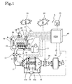
- Fig. 1 is a system configuration diagram of an exhaust gas purification system of an embodiment in accordance with the present invention
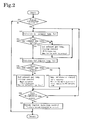
- Fig. 2 is a diagram for illustrating an example of forced regeneration control flow
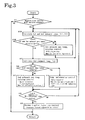
- Fig. 3 is a diagram for illustrating another example of forced regeneration control flow.
- Fig. 1 shows the configuration of an exhaust gas purification system 1 in accordance with an embodiment of the present invention.
- the exhaust gas purification system 1 is configured having an exhaust gas purification device 12 provided in the exhaust gas passage 11 of a diesel engine (internal combustion engine) 10.
- the exhaust gas purification device 12 is a continuous regeneration-type DPF (diesel particulate filter) device, and is configured having an upstream oxidation catalyst device 12a and a downstream catalyst-supporting filter device 12b.
- an exhaust brake valve 13 is provided upstream to the exhaust gas purification device 12, and an exhaust throttle valve 14 is provided downstream to the exhaust gas purification device 12.
- the relative positions of the exhaust brake valve 13 and the exhaust throttle valve 14 are not particularly limited, and either may be placed upstream to the other. Moreover, the relative positions of these valves with respect to the exhaust gas purification device 12 are not particularly limited. However, in consideration of the effectiveness of the exhaust brake, it is preferable to dispose the exhaust brake valve 13 upstream and the exhaust throttle valve 14 downstream. Additionally, a silencer 15 is provided downstream to the exhaust gas purification device 12.
- the oxidation catalyst device 12a is formed supporting an oxidation catalyst such as platinum (Pt) on a carrier body having a porous ceramic honeycomb or similar structure.
- the catalyst-supporting filter device 12b is formed as a monolith honeycomb wall-flow type filter or similar filter, wherein the inlets and outlets of the porous ceramic honeycomb channels are blocked in an alternating pattern.
- a catalyst such as platinum or cerium oxide is then supported on the filter portion.
- PM (particulate matter) present in an exhaust gas G is thus trapped at the porous ceramic walls.
- differential pressure sensors 31 are provided in conducting pipes coupled to either end of the exhaust gas purification device 12.
- an oxidation catalyst inlet exhaust temperature sensor 32 is provided upstream to the oxidation catalyst device 12a, and a filter inlet exhaust temperature sensor 33 is provided between the oxidation catalyst device 12a and the catalyst-supporting filter device 12b.
- the oxidation catalyst inlet exhaust temperature sensor 32 detects a first exhaust gas temperature Tg1, being the temperature of the exhaust gas flowing into the oxidation catalyst device 12a.
- the filter inlet exhaust temperature sensor 33 detects a second exhaust gas temperature Tg2, being the temperature of the exhaust gas flowing into the catalyst-supporting filter device 12b.
- an intake passage 16 there are provided an air cleaner 17, a MAF sensor (intake air mass sensor) 34, an intake throttle valve 18, and an intake temperature sensor 35 for detecting the intake temperature Ta.
- the intake throttle valve 18 adjusts the quantity of air A entering the intake manifold.
- the output values of these sensors are input into a control device (ECU: Engine Control Unit) 40 that conducts regeneration control for the exhaust gas purification device 12, in addition to conducting general control for the engine 10.
- a control device ECU: Engine Control Unit
- components such as the intake throttle valve 18, a fuel injection device (injection nozzle) 19, the exhaust brake valve 13, the exhaust throttle valve 14, and an EGR valve 22 are controlled.
- the EGR valve 22 is provided along with an EGR cooler 21 in an EGR passage 21, and adjusts the EGR quantity.
- the fuel injection device 19 is coupled to a common-rail injection system (not shown in the drawings) that temporarily stores high-pressure fuel raised in pressure by a fuel pump (not shown in the drawings).
- a fuel pump (not shown in the drawings).
- information is input into the control device 40, such as information on the accelerator opening degree from an accelerator position sensor (APS) 36 and information on the engine revolutions from a revolutions sensor 37, as well as information such as vehicle speed and cooling water temperature.
- An electricity time signal is output from the control device 40 such that a predefined quantity of fuel is injected from the fuel injection device 19.
- a blinking lamp (DPF lamp) 23 acting as warning means, a malfunction lamp 24, and a manual regeneration button (manual regeneration switch) 25 are provided, such that the regeneration control of the exhaust gas purification device 12 may be conducted by not only automatic forced regeneration while traveling, but also forced regeneration when the driver arbitrarily stops the vehicle. Via these alert means 23 and 24, the driver is alerted when the trapped amount of PM at the catalyst-supporting filter device 12b exceeds a fixed amount and the catalyst-supporting filter device 12b becomes plugged.
- PM is trapped during ordinary operation.
- the system is monitored to determine whether or not it is time to regenerate. If it is determined that it is time to regenerate, a warning is issued or automatic regeneration while traveling is conducted. In the case of a warning, manual regeneration is conducted as a result of the driver receiving the warning and operating a manual regeneration button 25.
- forced regeneration is conducted, being either manual regeneration or automatic regeneration while traveling.
- forced regeneration is conducted according to a control flow like those shown by way of example in Figs. 2 and 3 .
- a second exhaust gas temperature Tg2 detected by the filter inlet exhaust temperature sensor 33 is used as the catalyst temperature index temperature that indicates the temperature (bed temperature) of the oxidation catalyst.
- Tc1 a predefined first judgment temperature
- the second exhaust gas temperature Tg2 detected by the filter inlet exhaust temperature sensor 33 is also used as the filter temperature index temperature that indicates the temperature of the catalyst-supporting filter device 12b.
- a temperature maintenance control is conducted by multi-injection, without conducting post-injection.
- step S11 it is first determined in step S11 whether or not forced regeneration control is to be conducted, whether by automatic regeneration while traveling or manual regeneration. If forced regeneration control is not to be conducted, the process returns without executing forced regeneration control, and ordinary operation control is conducted. If it is determined that forced regeneration control should be conducted in step S11, the process proceeds to step S12.
- forced regeneration control is conducted.
- manual regeneration the driver who is encouraged to conduct manual regeneration, stops the vehicle and operates the manual regeneration button 25, thereby commencing forced regeneration control.
- the blinking lamp (DPF lamp) 23 that acts as warning means is made to blink, thereby encouraging the driver to conduct manual regeneration of the DPF.
- This differential pressure being detected by the differential pressure sensors 31 that measures the pressure difference before and after the exhaust gas purification device 12.
- forced regeneration control commences when it is detected from the detected values of the differential pressure sensors 31 or other means that the amount of trapped PM at the catalyst-supporting filter device 12b has exceeded a fixed amount.
- the first judgment temperature Tc1 is the temperature (200 °C to 250 °C, for example) at which HC (i.e., unburned fuel supplied by post-injection) is sufficiently oxidized by the oxidation catalyst of the oxidation catalyst device 12a. Such oxidation occurs when the second exhaust gas temperature (catalyst temperature index temperature) Tg2, being the exhaust gas temperature detected by the filter inlet exhaust temperature sensor 33, reaches the first judgment temperature Tc1.
- a value that changes according to current number of engine revolutions Ne may also be used as the first judgment temperature Tc1.
- the first exhaust gas temperature Tg1 detected by the oxidation catalyst inlet exhaust temperature sensor 32 may also be used.
- step S13 the second exhaust gas temperature (catalyst temperature index temperature) Tg2 is checked.
- a first exhaust gas temperature raising control is conducted for a predefined time ⁇ t1 (a time related to the check interval for the second exhaust gas temperature Tg2 in step S13) in step S14.
- multi-injection is conducted on the basis of the map data for the first multi-injection, and without post-injection.
- first a fuel injection quantity is calculated from information such as the detected engine revolutions and the detected accelerator opening degree.
- injection quantities and injection timings for multi-injection are calculated by referring to the map data for the first multi-injection, and then multi-injection is conducted.
- the map data for the first multi-injection that determines the injection quantities and injection timings for the multi-injection is based on engine revolutions and fuel injection quantities. Stated differently, the map data is based on fuel injection quantities calculated from information such as the detected accelerator opening degree.
- This map data is configured in advance by experiment, calculation, or similar methods, and is then input into the control device.
- the injection quantities for multi-injection are increased, and the injection timings for multi-injection are delayed to be later than the fuel injection timings for ordinary operation.
- the exhaust gas temperature raising efficiency is increased, and it becomes possible to rapidly raise the temperature of the exhaust gas.
- the above is used in conjunction with the exhaust brake valve 13 when the vehicle is stopped.
- the exhaust brake valve 13 By closing the exhaust brake valve 13, the escape of heat is prevented while also increasing engine load. In so doing, the exhaust gas temperature is raised efficiently and in a short time, thereby improving the performance to heat the oxidation catalyst device 12a.
- step S13 the process returns to step S12.
- step S13 the process determines that the second exhaust gas temperature Tg2 is equal to or greater than the predefined first judgment temperature Tc1
- the process proceeds to step S15.
- the second exhaust gas temperature Tg2 detected by the filter inlet exhaust temperature sensor 33 as well as the first exhaust gas temperature Tg1 detected by the oxidation catalyst inlet exhaust temperature sensor 32, as the catalyst temperature index temperature that indicates the temperature of the oxidation catalyst.
- the first judgment temperature Tc1 and a third judgment temperature Tc3 are used as the predefined judgment temperatures with respect to either exhaust gas temperature.
- the second exhaust gas temperature Tg2 exceeds the first judgment temperature Tc1
- the first exhaust gas temperature Tg1 exceeds the third judgment temperature Tc3 unburned fuel is supplied upstream to the oxidation catalyst device 12a by post-injection.
- step S12A the third judgment temperature Tc3 is calculated in addition to the first judgment temperature Tc1.
- step S13A it is determined both whether or not the second exhaust gas temperature Tg2 is equal to or greater than the first judgment temperature Tc1, and whether or not the first exhaust gas temperature Tg1 is equal to or greater than the third judgment temperature Tc3.
- the process then proceeds to step S15 only in the case where the second exhaust gas temperature Tg2 is equal to or greater than the first judgment temperature Tc1, and in addition, the first exhaust gas temperature Tg1 is equal to or greater than the third judgment temperature Tc3. In all other cases, the process proceeds to step S14.
- the second judgment temperature Tc2 is calculated.
- the second judgment temperature Tc2 is the target temperature for the second exhaust gas temperature raising control in step S17.
- the second exhaust gas temperature (filter temperature index temperature) Tg2 i.e., the exhaust gas temperature detected by the filter inlet exhaust temperature sensor 33
- the second judgment temperature Tc2 is taken to be a value higher than the temperature (350 °C, for example) at which PM starts to burn, such as approximately 500 °C, for example.
- the value of the second judgment temperature Tc2 may also be changed in multiple stages depending on time.
- step S16 the second exhaust gas temperature (filter temperature index temperature) Tg2 is checked.
- the process proceeds to the second exhaust gas temperature raising control in step S17.
- the process proceeds to the temperature maintenance control in step S18.
- step S17 the second exhaust gas temperature raising control is conducted for a predefined time ⁇ t2 (a time related to the check interval for the second exhaust gas temperature Tg2 in step S16).
- multi-injection is conducted on the basis of map data for the second multi-injection, this map data being different from the map data for the first multi-injection.
- the map data for the second multi-injection which determines the injection quantities and injection timings for multi-injection, is based on engine revolutions and fuel injection quantities. State differently, the map data is based on a fuel injection quantity calculated from information such as the detected accelerator opening degree. This map data is configured in advance by experiment, calculation, or similar methods, and is input into the control device.
- the injection quantities for multi-injection are reduced to the quantities necessary for maintaining the exhaust gas temperature.
- the delay in the injection timings for multi-injection is also reduced to be less than that of injection timings for multi-injection during the first exhaust gas temperature raising control in step S14.
- the temperature of the exhaust gas is maintained to a certain degree.
- fuel is supplied to the oxidation catalyst device 12a by post-injection, the fuel being oxidized by the oxidation catalyst, thereby raising the temperature of exhaust gas flowing into the catalyst-supporting filter device 12b.
- the above is used in conjunction with an exhaust throttle valve 14 when the vehicle is stopped.
- the exhaust brake valve 13 is fully opened, and the exhaust throttle valve 14 is fully closed.
- the passage area can be increased compared to when the exhaust brake valve 13 is closed, thereby reducing engine load. For this reason, increase in the in-cylinder temperature is reduced, thereby enabling post-injection.
- the raising of the exhaust gas temperature is maintained by the multi-injection of the second exhaust gas temperature raising control, while in addition, unburned fuel (HC) is supplied to the exhaust gas by post-injection.
- This unburned fuel is oxidized by the oxidation catalyst device 12a, and by using the heat from oxidation, the temperature of the exhaust gas can be further increased.
- Tg2 of the heated exhaust gas reaches or exceeds the second judgment temperature Tc2, PM trapped at the catalyst-supporting filter device 12b burns.
- the second exhaust gas temperature Tg2 may be continuously raised in temperature until reaching the control target temperature Tc2. Alternatively, the temperature raising may be conducted in two stages or multiple stages. After step S17, the process proceeds to step S19.
- a temperature maintenance control is conducted for a predefined time ⁇ t3 (a time related to the continuous time check interval for second exhaust gas temperature Tg2 in step S16) in step S18.
- ⁇ t3 a time related to the continuous time check interval for second exhaust gas temperature Tg2 in step S16
- multi-injection is conducted without post-injection as part of an in-cylinder injection of the engine 10.
- step S18 a count of the cumulative PM combustion time is conducted.
- step S19 in order to determine whether or not the regeneration control is ended, the cumulative PM combustion time (ta) is checked. In this check, it is checked whether or not the cumulative PM combustion time (ta) exceeds a predefined judgment time Tac. More specifically, if the cumulative PM combustion time (ta) exceeds the predefined judgment time Tac, regeneration control has completed, and the process proceeds to step S20. If the cumulative PM combustion time (ta) does not exceed the predefined judgment time tac, regeneration control has not completed, and the process returns to step S12.
- the first exhaust gas temperature raising control in step S14, the second exhaust gas temperature raising control in step S17, or the temperature maintenance control in step S18 is then conducted until the cumulative PM combustion time (ta) exceeds the predefined judgment time tac.
- step S20 forced regeneration control is ended. If the vehicle is stopped, the exhaust brake valve 13 and the exhaust throttle valve 14 are returned to their ordinary operating states, and ordinary injection control is resumed. After that, the process returns.
- the system is continuously monitored for the commencement of vehicle travel. Once travel commences, the process returns, the control flow is aborted, and the process returns to a predefined control such as ordinary operation control.
- the second exhaust gas temperature (catalyst temperature index temperature) Tg2 being the temperature of the exhaust gas detected by the filter inlet exhaust temperature sensor 33, is compared to a predefined first judgment temperature Tc1.
- the temperature of exhaust gas flowing into the catalyst-supporting filter device 12b is compared to the first judgment temperature Tc1.
- a first exhaust gas temperature raising control S14 is conducted, wherein multi-injection is conducted without post-injection as part of an in-cylinder fuel injection control.
- a second exhaust gas temperature raising control S17 is conducted, wherein post-injection is conducted in addition to multi-injection as part of an in-cylinder fuel injection control. Furthermore, the injection quantities and injection timings for the multi-injection conducted in the first exhaust gas temperature raising control S14 are calculated based on map data for the first multi-injection. The injection quantities and injection timings for the multi-injection conducted in the second exhaust gas temperature raising control S17 can be calculated based on map data for the second multi-injection, the map data for the second multi-injection being different from the map data for the first multi-injection.
- the injection quantities for the multi-injection are increased, and the injection timings for the multi-injection are delayed to be later than the fuel injection timings during ordinary operation.
- the injection quantities for the multi-injection are decreased to the quantities necessary for maintaining the exhaust gas temperature, while the delay in the injection timings for the multi-injection is reduced compared to the injection timings for the multi-injection in the first exhaust gas temperature raising control S14.
- An exhaust gas purification system 1 is provided, having an oxidation catalyst device 12a and a catalyst-supporting filter device 12b for purifying PM present in exhaust gas provided in the exhaust gas passage 11 of a diesel engine 10.
- multi-injection is conducted as part of an in-cylinder fuel injection during forced regeneration of the catalyst-supporting filter device 12b.
- Control maps for multi-injection are configured so as to be different for a first exhaust gas temperature raising control S14, wherein a catalyst temperature index temperature Tg2 (or Tg1) is raised to a first judgment temperature Tc1 using multi-injection only, and a subsequent second exhaust gas temperature raising control S17, wherein post-injection is conducted in addition to multi-injection in order to raise a filter temperature index temperature Tg2 to the first judgment temperature Tc1.
- the injection quantities for multi-injection are increased while the injection timings are delayed, thereby shortening the temperature raising time.
- the injection quantities for multi-injection are throttled, and the injection timings are controlled in the opposite direction to reduce the delay to less than that of the injection timings of the first exhaust gas temperature raising control S14, thereby maintaining the elevated temperature of the exhaust gas. For this reason, exhaust gas is efficiently raised in temperature and the temperature of the exhaust gas is maintained.
- exhaust gas flowing into the catalyst-supporting filter device 12b can be rapidly raised in temperature. In so doing, the time for forced regeneration can be shortened, and the fuel consumption for forced regeneration can be improved.
- an upstream oxidation catalyst device 12a and a downstream catalyst-supporting filter device (DPF) 12b were described by way of example as the exhaust gas purification device 12 of the exhaust gas purification system 1.
- the exhaust gas purification device may also be configured with a filter (DPF) supporting an oxidation catalyst.
- the exhaust gas purification method and exhaust gas purification system of the present invention can be installed in an internal combustion engine or similar engine onboard an automobile and used to highly advantageous effect with respect to an exhaust gas purification device wherein an oxidation catalyst device supporting an oxidation catalyst and a DPF are disposed in order from the upstream side in the exhaust gas passage of an internal combustion engine, or with respect an exhaust gas purification system provided with a DPF supporting an oxidation catalyst in the exhaust gas passage of an internal combustion engine.
Landscapes
- Engineering & Computer Science (AREA)
- Chemical & Material Sciences (AREA)
- Combustion & Propulsion (AREA)
- Mechanical Engineering (AREA)
- General Engineering & Computer Science (AREA)
- Biomedical Technology (AREA)
- Health & Medical Sciences (AREA)
- Environmental & Geological Engineering (AREA)
- Analytical Chemistry (AREA)
- General Chemical & Material Sciences (AREA)
- Oil, Petroleum & Natural Gas (AREA)
- Chemical Kinetics & Catalysis (AREA)
- Processes For Solid Components From Exhaust (AREA)
- Filtering Of Dispersed Particles In Gases (AREA)
- Exhaust Gas Treatment By Means Of Catalyst (AREA)
Applications Claiming Priority (2)
| Application Number | Priority Date | Filing Date | Title |
|---|---|---|---|
| JP2006074379A JP3979437B1 (ja) | 2006-03-17 | 2006-03-17 | 排気ガス浄化システムの制御方法及び排気ガス浄化システム |
| PCT/JP2006/323183 WO2007108167A1 (ja) | 2006-03-17 | 2006-11-21 | 排気ガス浄化システムの制御方法及び排気ガス浄化システム |
Publications (3)
| Publication Number | Publication Date |
|---|---|
| EP1998015A1 true EP1998015A1 (de) | 2008-12-03 |
| EP1998015A4 EP1998015A4 (de) | 2015-04-22 |
| EP1998015B1 EP1998015B1 (de) | 2017-06-21 |
Family
ID=38522205
Family Applications (1)
| Application Number | Title | Priority Date | Filing Date |
|---|---|---|---|
| EP06833033.1A Ceased EP1998015B1 (de) | 2006-03-17 | 2006-11-21 | Verfahren zur steuerung eines abgasreinigungssystems und abgasreinigungssystem |
Country Status (5)
| Country | Link |
|---|---|
| US (1) | US8549843B2 (de) |
| EP (1) | EP1998015B1 (de) |
| JP (1) | JP3979437B1 (de) |
| CN (1) | CN101400874B (de) |
| WO (1) | WO2007108167A1 (de) |
Cited By (1)
| Publication number | Priority date | Publication date | Assignee | Title |
|---|---|---|---|---|
| EP3502431A1 (de) * | 2017-12-20 | 2019-06-26 | Kubota Corporation | Motor |
Families Citing this family (17)
| Publication number | Priority date | Publication date | Assignee | Title |
|---|---|---|---|---|
| US7818960B2 (en) * | 2007-03-14 | 2010-10-26 | Gm Global Technology Operations, Inc. | SCR cold start heating system for a diesel exhaust |
| JP5326502B2 (ja) * | 2008-11-04 | 2013-10-30 | 日産自動車株式会社 | 内燃機関の排気浄化装置 |
| JP5671786B2 (ja) * | 2009-05-29 | 2015-02-18 | いすゞ自動車株式会社 | 排気浄化装置 |
| US8350682B2 (en) * | 2009-06-12 | 2013-01-08 | Mack Trucks, Inc. | DPF warning system |
| US20110041361A1 (en) * | 2009-08-19 | 2011-02-24 | Mccann Carol U | Footware with decorative tongue |
| JP5864901B2 (ja) * | 2011-05-19 | 2016-02-17 | 日野自動車株式会社 | パティキュレートフィルタの手動再生方法 |
| CN102383905B (zh) * | 2011-11-08 | 2012-12-26 | 上海三一重机有限公司 | 一种工程机械用发动机后处理再生的智能控制方法 |
| JP2015048713A (ja) * | 2013-08-29 | 2015-03-16 | ヤンマー株式会社 | 作業車両 |
| US9689331B1 (en) * | 2016-03-24 | 2017-06-27 | GM Global Technology Operations LLC | Method and apparatus to control fuel injection in an internal combustion engine |
| JP6733595B2 (ja) * | 2017-04-24 | 2020-08-05 | いすゞ自動車株式会社 | フィルタ再生制御装置およびフィルタ再生制御方法 |
| JP6891629B2 (ja) * | 2017-05-19 | 2021-06-18 | いすゞ自動車株式会社 | エンジン及びその制御方法 |
| US11280284B1 (en) * | 2019-05-31 | 2022-03-22 | OTR Performance, Inc. | Systems and methods for remotely controlling subsystems including exhaust subsystems of a vehicle |
| CN111350597B (zh) * | 2020-03-25 | 2022-05-20 | 重庆康明斯发动机有限公司 | 一种汽车废气排放的控制方法、控制系统、车辆 |
| CN112691547A (zh) * | 2021-01-11 | 2021-04-23 | 中国船舶重工集团公司第七一一研究所 | 基于可编程逻辑控制器的尾气脱硝控制系统 |
| WO2022155510A1 (en) * | 2021-01-14 | 2022-07-21 | Optiimus Technologies, Inc. | Method and apparatus for using biofuels in engines having emission control systems |
| CN114607515B (zh) * | 2022-03-17 | 2023-01-06 | 潍柴动力股份有限公司 | 发动机喷油控制方法、装置、设备及存储介质 |
| JP2025085210A (ja) * | 2023-11-24 | 2025-06-05 | いすゞ自動車株式会社 | 車両 |
Family Cites Families (15)
| Publication number | Priority date | Publication date | Assignee | Title |
|---|---|---|---|---|
| JP3485344B2 (ja) * | 1994-03-23 | 2004-01-13 | 株式会社日本自動車部品総合研究所 | 内燃機関の排気微粒子浄化装置 |
| JP2002066813A (ja) | 2000-08-25 | 2002-03-05 | Kosei Aluminum Co Ltd | チャックのスペーサ及びスペーサを使用した加工方法 |
| DE60212079T2 (de) | 2001-02-20 | 2006-12-07 | Isuzu Motors Ltd. | Verfahren zur Steuerung der Kraftstoffeinspritzung für Dieselmotoren und Regenerationssteuerungsverfahren für Abgasnachbehandlungsvorrichtung |
| JP4178928B2 (ja) * | 2002-12-02 | 2008-11-12 | 日産自動車株式会社 | 排気浄化装置 |
| JP2004225579A (ja) | 2003-01-21 | 2004-08-12 | Isuzu Motors Ltd | 排気ガス浄化システム |
| JP2005048747A (ja) | 2003-07-31 | 2005-02-24 | Nissan Motor Co Ltd | 内燃機関の燃焼制御装置 |
| JP4150308B2 (ja) | 2003-08-01 | 2008-09-17 | 日産ディーゼル工業株式会社 | 排気浄化装置 |
| JP4070687B2 (ja) | 2003-08-11 | 2008-04-02 | 日産ディーゼル工業株式会社 | 排気浄化装置 |
| JP4333289B2 (ja) * | 2003-09-03 | 2009-09-16 | いすゞ自動車株式会社 | 排気ガス浄化システム |
| JP4517682B2 (ja) * | 2004-03-09 | 2010-08-04 | いすゞ自動車株式会社 | 排気ガス浄化システム |
| JP4466158B2 (ja) | 2004-03-30 | 2010-05-26 | いすゞ自動車株式会社 | 排気ガス浄化システムの制御方法及び排気ガス浄化システム |
| JP2005291057A (ja) | 2004-03-31 | 2005-10-20 | Mitsubishi Fuso Truck & Bus Corp | 排気ガス浄化装置 |
| JP4161930B2 (ja) * | 2004-04-06 | 2008-10-08 | いすゞ自動車株式会社 | 排気ガス浄化システムの制御方法及び排気ガス浄化システム |
| US7251932B2 (en) * | 2004-11-08 | 2007-08-07 | Southwest Research Institute | Exhaust system and method for controlling exhaust gas flow and temperature through regenerable exhaust gas treatment devices |
| JP2006183599A (ja) * | 2004-12-28 | 2006-07-13 | Nissan Motor Co Ltd | 内燃機関の排気浄化装置 |
-
2006
- 2006-03-17 JP JP2006074379A patent/JP3979437B1/ja not_active Expired - Fee Related
- 2006-11-21 EP EP06833033.1A patent/EP1998015B1/de not_active Ceased
- 2006-11-21 WO PCT/JP2006/323183 patent/WO2007108167A1/ja not_active Ceased
- 2006-11-21 US US12/224,605 patent/US8549843B2/en active Active
- 2006-11-21 CN CN2006800537316A patent/CN101400874B/zh not_active Expired - Fee Related
Cited By (2)
| Publication number | Priority date | Publication date | Assignee | Title |
|---|---|---|---|---|
| EP3502431A1 (de) * | 2017-12-20 | 2019-06-26 | Kubota Corporation | Motor |
| US10890090B2 (en) | 2017-12-20 | 2021-01-12 | Kubota Corporation | Engine |
Also Published As
| Publication number | Publication date |
|---|---|
| JP3979437B1 (ja) | 2007-09-19 |
| WO2007108167A1 (ja) | 2007-09-27 |
| JP2007247595A (ja) | 2007-09-27 |
| US20090007549A1 (en) | 2009-01-08 |
| EP1998015B1 (de) | 2017-06-21 |
| EP1998015A4 (de) | 2015-04-22 |
| CN101400874B (zh) | 2011-06-08 |
| US8549843B2 (en) | 2013-10-08 |
| CN101400874A (zh) | 2009-04-01 |
Similar Documents
| Publication | Publication Date | Title |
|---|---|---|
| CN101375026B (zh) | 废气净化方法以及废气净化系统 | |
| CN101379274B (zh) | 废气净化系统的控制方法及废气净化系统 | |
| EP1980738B1 (de) | Verfahren zur steuerung eines abgasreinigungssystems und abgasreinigungssystem | |
| EP1998015B1 (de) | Verfahren zur steuerung eines abgasreinigungssystems und abgasreinigungssystem | |
| EP1978219B1 (de) | Abgasreinigungsverfahren und abgasreinigungssystem | |
| EP1942263B1 (de) | Steuerverfahren für abgasreinigungssystem und abgasreinigungssystem | |
| JP4055808B2 (ja) | 排気ガス浄化システムの制御方法及び排気ガス浄化システム | |
| JP6729473B2 (ja) | フィルタ再生制御装置およびフィルタ再生制御方法 | |
| JP2005163652A (ja) | 排気浄化装置 | |
| JP5858224B2 (ja) | 排気浄化装置の再生装置 | |
| JP2024077201A (ja) | 内燃機関の触媒劣化診断装置 | |
| JP2007023876A (ja) | 排気ガス浄化システムの制御方法及び排気ガス浄化システム | |
| JP2011220252A (ja) | 後処理バーナシステムの燃焼昇温制御方法及び装置 |
Legal Events
| Date | Code | Title | Description |
|---|---|---|---|
| PUAI | Public reference made under article 153(3) epc to a published international application that has entered the european phase |
Free format text: ORIGINAL CODE: 0009012 |
|
| 17P | Request for examination filed |
Effective date: 20080917 |
|
| AK | Designated contracting states |
Kind code of ref document: A1 Designated state(s): DE FR GB IT |
|
| RBV | Designated contracting states (corrected) |
Designated state(s): DE FR GB IT |
|
| DAX | Request for extension of the european patent (deleted) | ||
| RA4 | Supplementary search report drawn up and despatched (corrected) |
Effective date: 20150324 |
|
| RIC1 | Information provided on ipc code assigned before grant |
Ipc: F02D 41/40 20060101ALI20150317BHEP Ipc: F01N 3/02 20060101AFI20150317BHEP Ipc: B01D 53/94 20060101ALI20150317BHEP Ipc: F02D 41/02 20060101ALI20150317BHEP |
|
| 17Q | First examination report despatched |
Effective date: 20160208 |
|
| REG | Reference to a national code |
Ref country code: DE Ref legal event code: R079 Ref document number: 602006052864 Country of ref document: DE Free format text: PREVIOUS MAIN CLASS: F01N0003020000 Ipc: F02D0041140000 |
|
| RIC1 | Information provided on ipc code assigned before grant |
Ipc: F01N 3/02 20060101ALI20160908BHEP Ipc: F01N 3/035 20060101ALI20160908BHEP Ipc: F01N 3/023 20060101ALI20160908BHEP Ipc: F02D 9/02 20060101ALI20160908BHEP Ipc: F02D 41/40 20060101ALI20160908BHEP Ipc: F02D 41/02 20060101ALI20160908BHEP Ipc: F02D 41/14 20060101AFI20160908BHEP Ipc: B01D 53/94 20060101ALI20160908BHEP |
|
| GRAP | Despatch of communication of intention to grant a patent |
Free format text: ORIGINAL CODE: EPIDOSNIGR1 |
|
| INTG | Intention to grant announced |
Effective date: 20161019 |
|
| GRAJ | Information related to disapproval of communication of intention to grant by the applicant or resumption of examination proceedings by the epo deleted |
Free format text: ORIGINAL CODE: EPIDOSDIGR1 |
|
| GRAP | Despatch of communication of intention to grant a patent |
Free format text: ORIGINAL CODE: EPIDOSNIGR1 |
|
| INTC | Intention to grant announced (deleted) | ||
| INTG | Intention to grant announced |
Effective date: 20170222 |
|
| GRAS | Grant fee paid |
Free format text: ORIGINAL CODE: EPIDOSNIGR3 |
|
| GRAA | (expected) grant |
Free format text: ORIGINAL CODE: 0009210 |
|
| AK | Designated contracting states |
Kind code of ref document: B1 Designated state(s): DE FR GB IT |
|
| REG | Reference to a national code |
Ref country code: GB Ref legal event code: FG4D |
|
| REG | Reference to a national code |
Ref country code: DE Ref legal event code: R096 Ref document number: 602006052864 Country of ref document: DE |
|
| REG | Reference to a national code |
Ref country code: FR Ref legal event code: PLFP Year of fee payment: 12 |
|
| PG25 | Lapsed in a contracting state [announced via postgrant information from national office to epo] |
Ref country code: IT Free format text: LAPSE BECAUSE OF FAILURE TO SUBMIT A TRANSLATION OF THE DESCRIPTION OR TO PAY THE FEE WITHIN THE PRESCRIBED TIME-LIMIT Effective date: 20170621 |
|
| REG | Reference to a national code |
Ref country code: DE Ref legal event code: R097 Ref document number: 602006052864 Country of ref document: DE |
|
| PLBE | No opposition filed within time limit |
Free format text: ORIGINAL CODE: 0009261 |
|
| STAA | Information on the status of an ep patent application or granted ep patent |
Free format text: STATUS: NO OPPOSITION FILED WITHIN TIME LIMIT |
|
| 26N | No opposition filed |
Effective date: 20180322 |
|
| REG | Reference to a national code |
Ref country code: FR Ref legal event code: PLFP Year of fee payment: 13 |
|
| PGFP | Annual fee paid to national office [announced via postgrant information from national office to epo] |
Ref country code: GB Payment date: 20210930 Year of fee payment: 16 |
|
| PGFP | Annual fee paid to national office [announced via postgrant information from national office to epo] |
Ref country code: DE Payment date: 20210929 Year of fee payment: 16 Ref country code: FR Payment date: 20211109 Year of fee payment: 16 |
|
| REG | Reference to a national code |
Ref country code: DE Ref legal event code: R119 Ref document number: 602006052864 Country of ref document: DE |
|
| GBPC | Gb: european patent ceased through non-payment of renewal fee |
Effective date: 20221121 |
|
| PG25 | Lapsed in a contracting state [announced via postgrant information from national office to epo] |
Ref country code: GB Free format text: LAPSE BECAUSE OF NON-PAYMENT OF DUE FEES Effective date: 20221121 Ref country code: DE Free format text: LAPSE BECAUSE OF NON-PAYMENT OF DUE FEES Effective date: 20230601 |
|
| PG25 | Lapsed in a contracting state [announced via postgrant information from national office to epo] |
Ref country code: FR Free format text: LAPSE BECAUSE OF NON-PAYMENT OF DUE FEES Effective date: 20221130 |