EP1996348B1 - Method to feed bars to a working machine and relative device - Google Patents
Method to feed bars to a working machine and relative device Download PDFInfo
- Publication number
- EP1996348B1 EP1996348B1 EP07726600A EP07726600A EP1996348B1 EP 1996348 B1 EP1996348 B1 EP 1996348B1 EP 07726600 A EP07726600 A EP 07726600A EP 07726600 A EP07726600 A EP 07726600A EP 1996348 B1 EP1996348 B1 EP 1996348B1
- Authority
- EP
- European Patent Office
- Prior art keywords
- bars
- drawing assembly
- loading
- assembly
- magnetic means
- Prior art date
- Legal status (The legal status is an assumption and is not a legal conclusion. Google has not performed a legal analysis and makes no representation as to the accuracy of the status listed.)
- Active
Links
- 238000000034 method Methods 0.000 title claims abstract description 13
- 238000009825 accumulation Methods 0.000 claims abstract description 13
- 238000013519 translation Methods 0.000 claims description 6
- 238000005452 bending Methods 0.000 description 2
- 230000015572 biosynthetic process Effects 0.000 description 2
- 238000011161 development Methods 0.000 description 2
- 238000003780 insertion Methods 0.000 description 2
- 230000037431 insertion Effects 0.000 description 2
- 230000001105 regulatory effect Effects 0.000 description 2
- 238000007493 shaping process Methods 0.000 description 2
- 230000003213 activating effect Effects 0.000 description 1
- 230000004913 activation Effects 0.000 description 1
- 238000007792 addition Methods 0.000 description 1
- 238000010009 beating Methods 0.000 description 1
- 230000001419 dependent effect Effects 0.000 description 1
- 230000000694 effects Effects 0.000 description 1
- 238000012986 modification Methods 0.000 description 1
- 230000004048 modification Effects 0.000 description 1
- 230000010355 oscillation Effects 0.000 description 1
- 230000000630 rising effect Effects 0.000 description 1
- 239000007787 solid Substances 0.000 description 1
- 238000011144 upstream manufacturing Methods 0.000 description 1
Images

Classifications
-
- B—PERFORMING OPERATIONS; TRANSPORTING
- B21—MECHANICAL METAL-WORKING WITHOUT ESSENTIALLY REMOVING MATERIAL; PUNCHING METAL
- B21F—WORKING OR PROCESSING OF METAL WIRE
- B21F23/00—Feeding wire in wire-working machines or apparatus
- B21F23/005—Feeding discrete lengths of wire or rod
-
- B—PERFORMING OPERATIONS; TRANSPORTING
- B21—MECHANICAL METAL-WORKING WITHOUT ESSENTIALLY REMOVING MATERIAL; PUNCHING METAL
- B21D—WORKING OR PROCESSING OF SHEET METAL OR METAL TUBES, RODS OR PROFILES WITHOUT ESSENTIALLY REMOVING MATERIAL; PUNCHING METAL
- B21D43/00—Feeding, positioning or storing devices combined with, or arranged in, or specially adapted for use in connection with, apparatus for working or processing sheet metal, metal tubes or metal profiles; Associations therewith of cutting devices
- B21D43/006—Feeding elongated articles, such as tubes, bars, or profiles
-
- B—PERFORMING OPERATIONS; TRANSPORTING
- B21—MECHANICAL METAL-WORKING WITHOUT ESSENTIALLY REMOVING MATERIAL; PUNCHING METAL
- B21F—WORKING OR PROCESSING OF METAL WIRE
- B21F23/00—Feeding wire in wire-working machines or apparatus
- B21F23/005—Feeding discrete lengths of wire or rod
- B21F23/007—Feeding discrete lengths of wire or rod using pick-up means, e.g. for isolating a predefined number of wires from a bundle
Definitions
- the present invention concerns a method to feed bars to a working machine as per the preamble of claim 10 and the relative feeder device as per the preamble of claim 1.
- the features mentioned in the preamble are disclosed in WO-A-2005/080021 .
- the working machine to which the invention refers is advantageously a stirrup-making machine, a bending machine, a shaping machine, a tying machine or other type of analogous or comparable machine.
- the feeder device is suitable to pick up, in a substantially automatic manner, at least one bar at a time from a bundle of bars, and to unload it into a pre-loading position so as to form a store with a desired number of bars, and then to load, substantially in a single operation, possibly comprising one or more movements, all the bars that make up the store into the drawing assembly of said working machine, so as to allow them to be sent for working, while the feeder device can start a new cycle to pick up bars from the bundle and form the store.
- Machines for working bars are known, which work one or more bars at a time, for example to achieve shaped pieces for the building trade or other type of product.
- the machines that use pre-sheared bars normally have one or more feed zones where a bundle is prepared, from which the bars to be sent to the machine are picked up on each occasion.
- the International Patent application WO 2005/080021 in the name of the Applicant, describes a feeder device comprising first magnetic means that separate an end segment of a plurality of bars from a bundle, and dispose said end segments on a plane raised with respect to said bundle, and second magnetic means which pick up, from the first magnetic means, one bar at a time from among the plurality of bars and unload it in a desired release position, to be more exact, in the drawing assembly of the working machine, so that said bar can be sent for working.
- This device although extremely efficient, has a limitation in those cases, very frequent, where the working machine is disposed to work several bars simultaneously, for example from 5 to 10, and is therefore equipped with a drawing assembly, for example with rollers or grippers, configured to accommodate the plurality of bars and to send them simultaneously for working.
- the known device must sequentially perform a plurality of cycles to pick up one bar at a time and deposit it in the drawing assembly, but then it must obviously stop for the whole time while the bars are being translated by the drawing assembly towards the working machine.
- Purpose of the present invention is therefore to increase the efficiency of a feeder device of the type indicated above so as to reduce the waiting times to obtain the loading of the desired number of bars in the relative drawing assembly.
- the feeder device comprises first magnetic means, disposed substantially in cooperation with an end part, or near the end, of the bundle of bars from which the bar or bars are to be picked up, and second magnetic means able to cooperate with said first magnetic means in order to selectively pick up the bar or bars to be sent to the machine.
- the first magnetic means are associated with first movement means able to move them so as to raise the end parts of a plurality of bars with respect to the bundle.
- the second magnetic means are associated with second movement means able to move them in a direction parallel, slant-wise or curvilinear with respect to the bars whose ends are held raised by the first magnetic means; the second magnetic means are suitable to pick up from the first magnetic means, selectively, the end part of one or more bars, advantageously one at a time, and to displace it and then release it in the desired position, in order to prepare it to be fed to the working machine.
- the second magnetic means are able to sequentially unload a plurality of bars, picked up one at a time from the first magnetic means, in a pre-loading position so as to form a store with said plurality of bars.
- the pre-loading and store-formation position is in proximity with the loading position defined by the space between the rollers of the drawing assembly.
- the bars are then loaded, substantially with a single operation, all together inside the drawing assembly, which is then activated to remove the bars from the bundle and send them for working.
- the store can already have been formed, so that a new plurality of bars, already ready, can be immediately loaded into the drawing assembly, substantially without any waiting times.
- the position of forming the store of bars to be loaded into the drawing assembly is substantially parallel but below the loading position into the drawing assembly.
- This solution determines the advantage of a lesser reciprocal interference between the rear segments of the bars already inserted into the drawing assembly and the rear segments of the bars that form the store, since the bars inserted into the drawing assembly, at least as far as their front segments are concerned, lie on a different plane from the plane where the front segments lie of the bars that form the store.
- the loading of the bars that form the store in the drawing assembly provides first a lifting movement to dispose the bars in an aligned position but external with respect to the position of insertion into the drawing assembly, and then a lateral translation to load said bars into the drawing assembly.
- the store is formed in a position aligned and external with respect to the loading position into the drawing assembly, and the insertion of the bars into the drawing assembly provides only a lateral translation.
- a feeder device 10 for bars 11 is suitable to be located upstream of a working machine such as a stirrup-making machine, shaping machine, bending machine, tying machine or any other machine of a similar type or even different.
- a working machine such as a stirrup-making machine, shaping machine, bending machine, tying machine or any other machine of a similar type or even different.
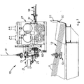
- the attached figures show a drawing assembly or drawer 27, which in this case consists of a pair of rollers, respectively upper roller 26a, and lower roller 26b. It comes within the scope of the invention that the drawing assembly 27 may consist of a gripper with alternating movement, or can be of any other type.
- the feeder device 10 is suitable to operate on bars 11 substantially of any length and/or diameter, guaranteeing in any case to pick up the bars in an orderly and efficient manner, and to count them without mistakes.
- the device 10 is suitable to pick up, from a bundle of bars 12 lying at least partly in a housing seating 30 (see fig. 7 ), one or more bars 11 at a time to send to the working machine.
- the housing seating 30 can comprise two, three or more pockets, possibly movable laterally, inside each of which bars 11 of the same size are disposed, but different from those in the other pockets.
- the feeder device 10 is movable with respect to the pockets, or other housing seating for the bars 11, in order to move selectively according to the type or size of bars 11 to be picked up.
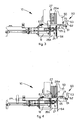
- the feeder device 10 is mounted in this case on a supporting frame 18 and comprises first magnetic means 13 consisting of a first magnetic or electromagnetic element 14 disposed advantageously during use in proximity with one end of the bars 11 of the bundle 12.
- the first magnetic means 13 comprise two or more magnetic or electromagnetic elements 14, disposed at several distinct points on the length of the bars 11, advantageously near their front ends.
- the first magnetic element 14 is located with a direction prevalently transverse to the longitudinal development of the bars 11 lying in the respective seating 30, and advantageously has a width such as to cover a considerable part of the width of the bundle 12.
- the first magnetic element 14 is mounted on an arm 31 associated with a first actuator 15, for example of the fluid-dynamic type, which achieves a movement thereof, in this case a substantially circular movement - direction 72 ( fig. 1 ).
- the magnetic element 14 can be correctly positioned in correspondence with the desired bundle 12 from which the bars 11 are to be removed.
- the magnetic element 14 is lowered towards the bundle 12, by means of the first actuator 15, to take the lower face thereof, comprising the attractive surface, to a position such as to exert an effect of magnetic attraction on the ends of the bars 11 located at the highest part of the bundle 12. Subsequently, the magnetic element 14 is returned upwards, magnetically lifting the ends of one layer of bars 11 disposed adjacent to each other so as to form substantially a plane ( fig. 1 ).
- the first magnetic element 14 is mounted on the relative arm 31 by means of an articulated joint 42, which allows it a certain freedom of oscillation in order to facilitate the picking up of the bars 11 even if the pockets have a curved and/or shaped bottom, and even if only a few residual bars 11 have remained at the bottom of the pockets.
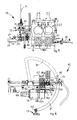
- second magnetic means 21 are activated, which comprise a second magnetic element 22 mounted at the end of a second actuator 23 mounted, in turn, on the supporting frame 18 ( fig. 2 ).
- the second magnetic means 21 comprise two or more magnetic elements 22 able to act at two or more distinct points on the length of the bars 11.
- the second actuator 23 is able to act in a direction 71, substantially perpendicular to the longitudinal development of the bars 11, so as to move, in this case horizontally, the second magnetic element 22 from a first, advanced pick-up position, wherein it moves into cooperation with the attractive surface of the first magnetic element 14 in order to pick up one or more bars 11 from it, advantageously one bar 11 at a time, to a second retracted release position.
- the second position according to the characteristic of the invention, it releases the end of the specific bar 11, which it has picked up from the first magnetic element 14, in correspondence with a supporting surface 61 of a thruster element 65 of an accumulation assembly 60.
- the bar 11 is released due to the interference on the bar 11 exerted by a stop element 50 during the movement of retraction of the second magnetic element 22.
- the position of the stop element 50 can advantageously be regulated at least in height according to the diameter of the bars 11 being worked, so as to create a housing made to size for said bars 11.
- the thruster element 65 comprises a front edge 62 facing upward, the upper end 63 of which is conformed as a lead-in slide to help the bars 11 to dispose themselves on the supporting surface 61, which in this case is substantially horizontal.
- the supporting surface 61 of the thruster element 65 is disposed substantially parallel but lying on a plane below the position of the loading plane for the bars 11 into the drawing assembly 27, which substantially corresponds to the upper surface of the lower roller 26b.
- the thruster element 65 When the first bar 11 has been released, the thruster element 65 performs a first movement towards the inside - direction 70 - to move the bar 11 to an inner waiting position, defined by the position of a substantially vertical abutment plate 64, and then returns backwards to position itself in a position to receive a new bar 11.
- the abutment plate 64 is substantially positioned flush with the lateral edge of the rollers 26a, 26b of the drawing assembly 27.
- the stop element 50 is then moved vertically to define the housing made to size for the bars 11.
- the drive of the thruster element 65 is obtained by activating a substantially horizontal actuator 66.
- the second magnetic element 22 performs a new cycle of picking up a bar 11 and unloading it onto the supporting surface 61 of the thruster element 65 when the latter has returned to its external start-of-cycle position.
- the thruster element 65 returns towards the inside, that is, towards the rollers 26a, 26b, so as to locate the new bar 11 in a stand-by position near the abutment plate 64 and adjacent to the first bar 11.
- the cycle to pick up, unload and laterally translate the bars 11 can be repeated a desired number of times so as to form the desired store, also according to the diameter of the bars 11, the configuration of the rollers 26a, 26b, and the requirements of the machine and the working cycle.
- the whole accumulation assembly 60 first performs a movement upwards - direction 73 - so as to locate the bars 11 in a position aligned with the upper surface of the lower roller 26b, immediately above the upper end of the abutment plate 64.
- the upper roller 26a is then positioned in the correct position to create a guide channel according to the diameter of the bars 11.
- a mobile abutment is provided, able to create said guide channel.
- the accumulation assembly 60 then performs a movement of lateral translation towards the rollers 26a, 26b, so as to thrust the bars 11 all together between the rollers 26a, 26b.
- an abutment roller 67 is advantageously present, which prevents the bars 11 from sliding beyond the loading position between the rollers 26a, 26b.
- the upper roller 26a closes on the lower roller 26b and the operation to remove the loaded bars 11 is started, and they are sent for working.
- the accumulation assembly 60 returns to its lowered, end-of-cycle position ( fig. 1 ) and the feeder device 10 can start a new cycle to form the store, as previously described.
- the accumulation assembly 60 when the formation of the store is terminated with the desired number of bars 11, the accumulation assembly 60 performs only a movement of lateral translation to insert the bars 11 between the rollers 26a, 26b, and then returns to its external position so as to allow on the one hand the drawing assembly 27 to be activated so as to feed the bars 11 to the working machine, and on the other hand to prepare a new store-forming cycle to start.
- a guide roller 39 is shown, in this case solid with the stop element 50 and disposed immediately above the lower roller 26a of the drawing assembly, the function of which is to guide the movement of the bars 11 when they are translated by the accumulation assembly 60 to the loading position between the rollers 26a, 26b.
- the position of the guide roller 39 can be regulated at least in height according to the diameter of the bars 11 being worked.
- the abutment plate 164 is associated with a positioning actuator, and remains stationary during the whole cycle to form the store of bars 11, so as to define the stop position thereof near the gap between the rollers 26a, 26b of the drawing assembly 27; during the loading step, the abutment plate 164 is raised, or lowered, allowing the bars 11 to be inserted in a removal position between the rollers 26a, 26b.
- header element 37 can be seen, associated with a movement actuator 38.
- the function of the header element 37 is to align the bars 11 with respect to each other, by acting repeatedly against the relative ends, after they have been picked up by the first magnetic element 14 and are kept raised with respect to the bundle.
- the header element 37 by selective activation of the movement actuator 38, performs some beating cycles against the ends of the bars 11, equalizing their longitudinal disposition so as to facilitate the subsequent step of loading into the drawing assembly 27 and the working to be carried out afterwards.
- the heading operation can be performed both when the bars 11 are held raised by the first magnetic means 13, and also on bars 11 which have already been unloaded onto the accumulation assembly 60.
- a sensor may be provided which signals the fact that the second magnetic element 22 is performing a purposeless travel without meeting bars 11, giving consent for a new descent of the first magnetic element 14 towards the bundle of bars 11 to perform a new pick-up.
- Another variant may provide that there are fixed stop elements present above the first magnetic element 14, which allow to discharge the bars 11, and make them fall back into the relative bundle, that have remained gripped on said first magnetic element 14 once the working cycle of the machine has been stopped. This discharge is obtained by rising the first magnetic element 14 by an extra travel beyond said stop elements. The discharge of the bars 11 can also be obtained, in the event of electromagnetic elements being used, by temporarily deactivating electric feed to said first magnetic element 14.
Landscapes
- Engineering & Computer Science (AREA)
- Mechanical Engineering (AREA)
- Feeding Of Articles To Conveyors (AREA)
- Specific Conveyance Elements (AREA)
- De-Stacking Of Articles (AREA)
- Feeding Of Workpieces (AREA)
Priority Applications (1)
| Application Number | Priority Date | Filing Date | Title |
|---|---|---|---|
| PL07726600T PL1996348T3 (pl) | 2006-03-07 | 2007-03-02 | Sposób wprowadzania prętów do maszyny do przetwarzania i odpowiednie urządzenie załadowcze |
Applications Claiming Priority (2)
| Application Number | Priority Date | Filing Date | Title |
|---|---|---|---|
| IT000050A ITUD20060050A1 (it) | 2006-03-07 | 2006-03-07 | Procedimento di alimentazione di barre ad una macchina di lavorazione e relativo dispositivo |
| PCT/EP2007/052006 WO2007101823A1 (en) | 2006-03-07 | 2007-03-02 | Method to feed bars to a working machine and relative device |
Publications (2)
| Publication Number | Publication Date |
|---|---|
| EP1996348A1 EP1996348A1 (en) | 2008-12-03 |
| EP1996348B1 true EP1996348B1 (en) | 2009-07-22 |
Family
ID=36926341
Family Applications (1)
| Application Number | Title | Priority Date | Filing Date |
|---|---|---|---|
| EP07726600A Active EP1996348B1 (en) | 2006-03-07 | 2007-03-02 | Method to feed bars to a working machine and relative device |
Country Status (12)
| Country | Link |
|---|---|
| US (1) | US20090007621A1 (it) |
| EP (1) | EP1996348B1 (it) |
| CN (1) | CN100586606C (it) |
| BR (1) | BRPI0707079B1 (it) |
| DE (1) | DE602007001684D1 (it) |
| DK (1) | DK1996348T3 (it) |
| ES (1) | ES2330487T3 (it) |
| HR (1) | HRP20090559T1 (it) |
| IT (1) | ITUD20060050A1 (it) |
| PL (1) | PL1996348T3 (it) |
| RU (1) | RU2440207C2 (it) |
| WO (1) | WO2007101823A1 (it) |
Cited By (3)
| Publication number | Priority date | Publication date | Assignee | Title |
|---|---|---|---|---|
| EP3159072A1 (en) * | 2015-10-23 | 2017-04-26 | Oscam S.r.l. | Apparatus for feeding metal bars in a controlled number to a manufacturing machine |
| ITUB20161172A1 (it) * | 2016-02-29 | 2017-08-29 | Schnell Spa | Metodo e apparecchiatura per alimentare automaticamente elementi di foggia allungata |
| RU2729481C2 (ru) * | 2016-06-13 | 2020-08-07 | М.Э.П. Маччине Элеттрониче Пьеатричи С.П.А. | Устройство и способ обработки металлических изделий |
Families Citing this family (4)
| Publication number | Priority date | Publication date | Assignee | Title |
|---|---|---|---|---|
| ITUD20080049A1 (it) * | 2008-03-07 | 2009-09-08 | Piegatrici Macch Elettr | Dispositivo alimentatore per barre e relativo procedimento di alimentazione |
| IT201600084716A1 (it) * | 2016-08-11 | 2018-02-11 | Buffoli Transfer S P A | Dispositivo per separare singole barre da un fascio |
| IT201600132141A1 (it) * | 2016-12-29 | 2018-06-29 | M E P Macch Elettroniche Piegatrici Spa | Apparato e metodo di manipolazione di barre, in particolare barre metalliche |
| AR113669A1 (es) | 2017-12-22 | 2020-05-27 | A C M S R L Automatismi Costruzioni Mecc | Aparato y método de elaboración de barras |
Family Cites Families (7)
| Publication number | Priority date | Publication date | Assignee | Title |
|---|---|---|---|---|
| DE1144569B (de) * | 1955-05-12 | 1963-02-28 | Asea Ab | Vorrichtung zum Einzelentnehmen von langgestreckten, gleichliegend gelagerten Werkstuecken aus magnetisierbarem Werkstoff |
| DE3151482A1 (de) * | 1981-12-24 | 1983-07-07 | SMS Schloemann-Siemag AG, 4000 Düsseldorf | Arbeitsverfahren zum bilden von unverschachtelten bzw. verschachtelten profilstabpaketen und einrichtungen zur durchfuehrung des verfahrens |
| WO1991009695A1 (en) * | 1989-12-29 | 1991-07-11 | Amada Company, Limited | A device for manipulating sheet metal pieces |
| AT406556B (de) * | 1996-02-16 | 2000-06-26 | Boehler Edelstahl | Verfahren und vorrichtung zur vereinzelung und weiterbearbeitung von metallstäben |
| ITBO20020241A1 (it) * | 2002-04-26 | 2003-10-27 | Schnell Spa | Metodo e apparecchiatura per alimentare automaticamente profilati metallici in barre in macchine per la lavorazione di tali profilati |
| ATE362409T1 (de) * | 2002-04-26 | 2007-06-15 | Schnell Spa | Verfahren und vorrichtung zum automatischen zuführen von stabförmigen metallprofilen in systemen zum bearbeiten dieser profile |
| ITUD20040012A1 (it) * | 2004-01-23 | 2004-04-23 | Piegatrici Macch Elettr | Dispositivo alimentatore per barre e relativo procedimento di alimentazione |
-
2006
- 2006-03-07 IT IT000050A patent/ITUD20060050A1/it unknown
-
2007
- 2007-03-02 EP EP07726600A patent/EP1996348B1/en active Active
- 2007-03-02 US US12/281,345 patent/US20090007621A1/en not_active Abandoned
- 2007-03-02 RU RU2008139608/02A patent/RU2440207C2/ru active
- 2007-03-02 PL PL07726600T patent/PL1996348T3/pl unknown
- 2007-03-02 BR BRPI0707079-9A patent/BRPI0707079B1/pt active IP Right Grant
- 2007-03-02 ES ES07726600T patent/ES2330487T3/es active Active
- 2007-03-02 CN CN200780008070A patent/CN100586606C/zh active Active
- 2007-03-02 DE DE602007001684T patent/DE602007001684D1/de active Active
- 2007-03-02 WO PCT/EP2007/052006 patent/WO2007101823A1/en active Application Filing
- 2007-03-02 DK DK07726600T patent/DK1996348T3/da active
-
2009
- 2009-10-19 HR HR20090559T patent/HRP20090559T1/xx unknown
Cited By (4)
| Publication number | Priority date | Publication date | Assignee | Title |
|---|---|---|---|---|
| EP3159072A1 (en) * | 2015-10-23 | 2017-04-26 | Oscam S.r.l. | Apparatus for feeding metal bars in a controlled number to a manufacturing machine |
| ITUB20161172A1 (it) * | 2016-02-29 | 2017-08-29 | Schnell Spa | Metodo e apparecchiatura per alimentare automaticamente elementi di foggia allungata |
| WO2017149452A1 (en) * | 2016-02-29 | 2017-09-08 | Schnell S.P.A. | Method and apparatus for automatically feeding elements of elongated shape |
| RU2729481C2 (ru) * | 2016-06-13 | 2020-08-07 | М.Э.П. Маччине Элеттрониче Пьеатричи С.П.А. | Устройство и способ обработки металлических изделий |
Also Published As
| Publication number | Publication date |
|---|---|
| CN101394956A (zh) | 2009-03-25 |
| WO2007101823A1 (en) | 2007-09-13 |
| PL1996348T3 (pl) | 2009-12-31 |
| ES2330487T3 (es) | 2009-12-10 |
| HRP20090559T1 (en) | 2009-11-30 |
| BRPI0707079A2 (pt) | 2011-04-19 |
| ITUD20060050A1 (it) | 2007-09-08 |
| US20090007621A1 (en) | 2009-01-08 |
| EP1996348A1 (en) | 2008-12-03 |
| BRPI0707079B1 (pt) | 2019-05-14 |
| DE602007001684D1 (de) | 2009-09-03 |
| RU2008139608A (ru) | 2010-04-20 |
| DK1996348T3 (da) | 2009-11-23 |
| RU2440207C2 (ru) | 2012-01-20 |
| CN100586606C (zh) | 2010-02-03 |
Similar Documents
| Publication | Publication Date | Title |
|---|---|---|
| EP1996348B1 (en) | Method to feed bars to a working machine and relative device | |
| EP2268429B1 (en) | Feeding device and method for bars | |
| KR101871332B1 (ko) | 판금 벤딩기 | |
| EP1706231B1 (en) | Feeder device for bars and relative feeding method | |
| EP3488960B1 (en) | Apparatus for laser or plasma cutting of pieces of laminar material wound in coil | |
| KR20190016584A (ko) | 금속 제품을 취급하기 위한 기기 및 방법 | |
| JP2799959B2 (ja) | プレス加工装置 | |
| EP1980341B1 (en) | Device and method for automatic loading of metal bars | |
| EP3670437B1 (en) | Multi-conveyor belt based insertion mechanism for pocketed coil springs | |
| EP1738843B1 (en) | Feed device for metal bars and relative method | |
| CN111348415B (zh) | 用于传送螺旋弹簧的磁升降平台 | |
| WO2011016870A1 (en) | Apparatus for forming a duct | |
| EP2136941B1 (en) | Feed device for metal bars, and associated method | |
| EP1177851A2 (en) | Loading device for metal wires and relative method | |
| KR101576762B1 (ko) | 단자 성형 금형 장치의 교환 장치 | |
| EP3578278B1 (en) | Method and apparatus for orderly transferring elements of elongated shape | |
| KR20230021007A (ko) | 장형 금속 제품의 가공 장치 및 방법 | |
| EP1378301B1 (en) | Method and apparatus for forming packs of stirrups and pack of stirrups thus formed | |
| EP2537604A1 (en) | Structure for accumulating metal bars |
Legal Events
| Date | Code | Title | Description |
|---|---|---|---|
| PUAI | Public reference made under article 153(3) epc to a published international application that has entered the european phase |
Free format text: ORIGINAL CODE: 0009012 |
|
| 17P | Request for examination filed |
Effective date: 20081006 |
|
| AK | Designated contracting states |
Kind code of ref document: A1 Designated state(s): AT BE BG CH CY CZ DE DK EE ES FI FR GB GR HU IE IS IT LI LT LU LV MC MT NL PL PT RO SE SI SK TR |
|
| AX | Request for extension of the european patent |
Extension state: HR RS |
|
| GRAP | Despatch of communication of intention to grant a patent |
Free format text: ORIGINAL CODE: EPIDOSNIGR1 |
|
| GRAS | Grant fee paid |
Free format text: ORIGINAL CODE: EPIDOSNIGR3 |
|
| GRAA | (expected) grant |
Free format text: ORIGINAL CODE: 0009210 |
|
| RAX | Requested extension states of the european patent have changed |
Extension state: RS Payment date: 20081006 Extension state: HR Payment date: 20081006 |
|
| RIN1 | Information on inventor provided before grant (corrected) |
Inventor name: DEL FABRO, GIORGIO |
|
| AK | Designated contracting states |
Kind code of ref document: B1 Designated state(s): AT BE BG CH CY CZ DE DK EE ES FI FR GB GR HU IE IS IT LI LT LU LV MC MT NL PL PT RO SE SI SK TR |
|
| AX | Request for extension of the european patent |
Extension state: HR RS |
|
| REG | Reference to a national code |
Ref country code: GB Ref legal event code: FG4D |
|
| REG | Reference to a national code |
Ref country code: CH Ref legal event code: EP |
|
| REG | Reference to a national code |
Ref country code: IE Ref legal event code: FG4D |
|
| REF | Corresponds to: |
Ref document number: 602007001684 Country of ref document: DE Date of ref document: 20090903 Kind code of ref document: P |
|
| REG | Reference to a national code |
Ref country code: RO Ref legal event code: EPE |
|
| REG | Reference to a national code |
Ref country code: CH Ref legal event code: NV Representative=s name: MICHELI & CIE SA |
|
| REG | Reference to a national code |
Ref country code: HR Ref legal event code: TUEP Ref document number: P20090559 Country of ref document: HR |
|
| REG | Reference to a national code |
Ref country code: GR Ref legal event code: EP Ref document number: 20090402556 Country of ref document: GR |
|
| REG | Reference to a national code |
Ref country code: DK Ref legal event code: T3 |
|
| REG | Reference to a national code |
Ref country code: HR Ref legal event code: T1PR Ref document number: P20090559 Country of ref document: HR |
|
| REG | Reference to a national code |
Ref country code: ES Ref legal event code: FG2A Ref document number: 2330487 Country of ref document: ES Kind code of ref document: T3 |
|
| REG | Reference to a national code |
Ref country code: PL Ref legal event code: T3 |
|
| NLV1 | Nl: lapsed or annulled due to failure to fulfill the requirements of art. 29p and 29m of the patents act | ||
| PG25 | Lapsed in a contracting state [announced via postgrant information from national office to epo] |
Ref country code: LT Free format text: LAPSE BECAUSE OF FAILURE TO SUBMIT A TRANSLATION OF THE DESCRIPTION OR TO PAY THE FEE WITHIN THE PRESCRIBED TIME-LIMIT Effective date: 20090722 Ref country code: FI Free format text: LAPSE BECAUSE OF FAILURE TO SUBMIT A TRANSLATION OF THE DESCRIPTION OR TO PAY THE FEE WITHIN THE PRESCRIBED TIME-LIMIT Effective date: 20090722 Ref country code: SE Free format text: LAPSE BECAUSE OF FAILURE TO SUBMIT A TRANSLATION OF THE DESCRIPTION OR TO PAY THE FEE WITHIN THE PRESCRIBED TIME-LIMIT Effective date: 20090722 Ref country code: IS Free format text: LAPSE BECAUSE OF FAILURE TO SUBMIT A TRANSLATION OF THE DESCRIPTION OR TO PAY THE FEE WITHIN THE PRESCRIBED TIME-LIMIT Effective date: 20091122 |
|
| PG25 | Lapsed in a contracting state [announced via postgrant information from national office to epo] |
Ref country code: LV Free format text: LAPSE BECAUSE OF FAILURE TO SUBMIT A TRANSLATION OF THE DESCRIPTION OR TO PAY THE FEE WITHIN THE PRESCRIBED TIME-LIMIT Effective date: 20090722 Ref country code: NL Free format text: LAPSE BECAUSE OF FAILURE TO SUBMIT A TRANSLATION OF THE DESCRIPTION OR TO PAY THE FEE WITHIN THE PRESCRIBED TIME-LIMIT Effective date: 20090722 Ref country code: SI Free format text: LAPSE BECAUSE OF FAILURE TO SUBMIT A TRANSLATION OF THE DESCRIPTION OR TO PAY THE FEE WITHIN THE PRESCRIBED TIME-LIMIT Effective date: 20090722 |
|
| REG | Reference to a national code |
Ref country code: AT Ref legal event code: UEP Ref document number: 437016 Country of ref document: AT Kind code of ref document: T |
|
| PG25 | Lapsed in a contracting state [announced via postgrant information from national office to epo] |
Ref country code: BG Free format text: LAPSE BECAUSE OF FAILURE TO SUBMIT A TRANSLATION OF THE DESCRIPTION OR TO PAY THE FEE WITHIN THE PRESCRIBED TIME-LIMIT Effective date: 20091022 Ref country code: PT Free format text: LAPSE BECAUSE OF FAILURE TO SUBMIT A TRANSLATION OF THE DESCRIPTION OR TO PAY THE FEE WITHIN THE PRESCRIBED TIME-LIMIT Effective date: 20091122 |
|
| PG25 | Lapsed in a contracting state [announced via postgrant information from national office to epo] |
Ref country code: CZ Free format text: LAPSE BECAUSE OF FAILURE TO SUBMIT A TRANSLATION OF THE DESCRIPTION OR TO PAY THE FEE WITHIN THE PRESCRIBED TIME-LIMIT Effective date: 20090722 Ref country code: EE Free format text: LAPSE BECAUSE OF FAILURE TO SUBMIT A TRANSLATION OF THE DESCRIPTION OR TO PAY THE FEE WITHIN THE PRESCRIBED TIME-LIMIT Effective date: 20090722 |
|
| PLBE | No opposition filed within time limit |
Free format text: ORIGINAL CODE: 0009261 |
|
| STAA | Information on the status of an ep patent application or granted ep patent |
Free format text: STATUS: NO OPPOSITION FILED WITHIN TIME LIMIT |
|
| PG25 | Lapsed in a contracting state [announced via postgrant information from national office to epo] |
Ref country code: BE Free format text: LAPSE BECAUSE OF FAILURE TO SUBMIT A TRANSLATION OF THE DESCRIPTION OR TO PAY THE FEE WITHIN THE PRESCRIBED TIME-LIMIT Effective date: 20090722 Ref country code: SK Free format text: LAPSE BECAUSE OF FAILURE TO SUBMIT A TRANSLATION OF THE DESCRIPTION OR TO PAY THE FEE WITHIN THE PRESCRIBED TIME-LIMIT Effective date: 20090722 |
|
| 26N | No opposition filed |
Effective date: 20100423 |
|
| PG25 | Lapsed in a contracting state [announced via postgrant information from national office to epo] |
Ref country code: MC Free format text: LAPSE BECAUSE OF NON-PAYMENT OF DUE FEES Effective date: 20100331 |
|
| PG25 | Lapsed in a contracting state [announced via postgrant information from national office to epo] |
Ref country code: IE Free format text: LAPSE BECAUSE OF NON-PAYMENT OF DUE FEES Effective date: 20100302 |
|
| PG25 | Lapsed in a contracting state [announced via postgrant information from national office to epo] |
Ref country code: MT Free format text: LAPSE BECAUSE OF FAILURE TO SUBMIT A TRANSLATION OF THE DESCRIPTION OR TO PAY THE FEE WITHIN THE PRESCRIBED TIME-LIMIT Effective date: 20090722 |
|
| PGRI | Patent reinstated in contracting state [announced from national office to epo] |
Ref country code: IT Effective date: 20110501 |
|
| PGRI | Patent reinstated in contracting state [announced from national office to epo] |
Ref country code: IT Effective date: 20110501 |
|
| PG25 | Lapsed in a contracting state [announced via postgrant information from national office to epo] |
Ref country code: CY Free format text: LAPSE BECAUSE OF FAILURE TO SUBMIT A TRANSLATION OF THE DESCRIPTION OR TO PAY THE FEE WITHIN THE PRESCRIBED TIME-LIMIT Effective date: 20090722 |
|
| PG25 | Lapsed in a contracting state [announced via postgrant information from national office to epo] |
Ref country code: HU Free format text: LAPSE BECAUSE OF FAILURE TO SUBMIT A TRANSLATION OF THE DESCRIPTION OR TO PAY THE FEE WITHIN THE PRESCRIBED TIME-LIMIT Effective date: 20100123 Ref country code: LU Free format text: LAPSE BECAUSE OF NON-PAYMENT OF DUE FEES Effective date: 20100302 |
|
| PG25 | Lapsed in a contracting state [announced via postgrant information from national office to epo] |
Ref country code: TR Free format text: LAPSE BECAUSE OF FAILURE TO SUBMIT A TRANSLATION OF THE DESCRIPTION OR TO PAY THE FEE WITHIN THE PRESCRIBED TIME-LIMIT Effective date: 20090722 |
|
| REG | Reference to a national code |
Ref country code: FR Ref legal event code: PLFP Year of fee payment: 10 |
|
| REG | Reference to a national code |
Ref country code: FR Ref legal event code: PLFP Year of fee payment: 11 |
|
| REG | Reference to a national code |
Ref country code: FR Ref legal event code: PLFP Year of fee payment: 12 |
|
| REG | Reference to a national code |
Ref country code: HR Ref legal event code: ODRP Ref document number: P20090559 Country of ref document: HR Payment date: 20190220 Year of fee payment: 13 |
|
| REG | Reference to a national code |
Ref country code: HR Ref legal event code: ODRP Ref document number: P20090559 Country of ref document: HR Payment date: 20200220 Year of fee payment: 14 |
|
| REG | Reference to a national code |
Ref country code: HR Ref legal event code: ODRP Ref document number: P20090559 Country of ref document: HR Payment date: 20210219 Year of fee payment: 15 |
|
| REG | Reference to a national code |
Ref country code: HR Ref legal event code: ODRP Ref document number: P20090559 Country of ref document: HR Payment date: 20220225 Year of fee payment: 16 |
|
| REG | Reference to a national code |
Ref country code: HR Ref legal event code: ODRP Ref document number: P20090559 Country of ref document: HR Payment date: 20230301 Year of fee payment: 17 |
|
| PGFP | Annual fee paid to national office [announced via postgrant information from national office to epo] |
Ref country code: FR Payment date: 20230316 Year of fee payment: 17 Ref country code: DK Payment date: 20230309 Year of fee payment: 17 |
|
| PGFP | Annual fee paid to national office [announced via postgrant information from national office to epo] |
Ref country code: PL Payment date: 20230227 Year of fee payment: 17 Ref country code: IT Payment date: 20230301 Year of fee payment: 17 |
|
| P01 | Opt-out of the competence of the unified patent court (upc) registered |
Effective date: 20230520 |
|
| PGFP | Annual fee paid to national office [announced via postgrant information from national office to epo] |
Ref country code: ES Payment date: 20230406 Year of fee payment: 17 Ref country code: CH Payment date: 20230402 Year of fee payment: 17 |
|
| REG | Reference to a national code |
Ref country code: HR Ref legal event code: ODRP Ref document number: P20090559 Country of ref document: HR Payment date: 20240221 Year of fee payment: 18 |
|
| PGFP | Annual fee paid to national office [announced via postgrant information from national office to epo] |
Ref country code: GR Payment date: 20240320 Year of fee payment: 18 |
|
| PGFP | Annual fee paid to national office [announced via postgrant information from national office to epo] |
Ref country code: AT Payment date: 20240306 Year of fee payment: 18 |
|
| PGFP | Annual fee paid to national office [announced via postgrant information from national office to epo] |
Ref country code: RO Payment date: 20240222 Year of fee payment: 18 Ref country code: DE Payment date: 20240306 Year of fee payment: 18 Ref country code: GB Payment date: 20240308 Year of fee payment: 18 |