EP1994875A1 - Vorrichtung zur beobachtung eines lebenden körpers - Google Patents
Vorrichtung zur beobachtung eines lebenden körpers Download PDFInfo
- Publication number
- EP1994875A1 EP1994875A1 EP07714591A EP07714591A EP1994875A1 EP 1994875 A1 EP1994875 A1 EP 1994875A1 EP 07714591 A EP07714591 A EP 07714591A EP 07714591 A EP07714591 A EP 07714591A EP 1994875 A1 EP1994875 A1 EP 1994875A1
- Authority
- EP
- European Patent Office
- Prior art keywords
- spectral
- image
- light
- color
- signal
- Prior art date
- Legal status (The legal status is an assumption and is not a legal conclusion. Google has not performed a legal analysis and makes no representation as to the accuracy of the status listed.)
- Granted
Links
Images


Classifications
-
- A—HUMAN NECESSITIES
- A61—MEDICAL OR VETERINARY SCIENCE; HYGIENE
- A61B—DIAGNOSIS; SURGERY; IDENTIFICATION
- A61B1/00—Instruments for performing medical examinations of the interior of cavities or tubes of the body by visual or photographical inspection, e.g. endoscopes; Illuminating arrangements therefor
- A61B1/00002—Operational features of endoscopes
- A61B1/00004—Operational features of endoscopes characterised by electronic signal processing
- A61B1/00009—Operational features of endoscopes characterised by electronic signal processing of image signals during a use of endoscope
- A61B1/000094—Operational features of endoscopes characterised by electronic signal processing of image signals during a use of endoscope extracting biological structures
-
- A—HUMAN NECESSITIES
- A61—MEDICAL OR VETERINARY SCIENCE; HYGIENE
- A61B—DIAGNOSIS; SURGERY; IDENTIFICATION
- A61B1/00—Instruments for performing medical examinations of the interior of cavities or tubes of the body by visual or photographical inspection, e.g. endoscopes; Illuminating arrangements therefor
- A61B1/06—Instruments for performing medical examinations of the interior of cavities or tubes of the body by visual or photographical inspection, e.g. endoscopes; Illuminating arrangements therefor with illuminating arrangements
- A61B1/0638—Instruments for performing medical examinations of the interior of cavities or tubes of the body by visual or photographical inspection, e.g. endoscopes; Illuminating arrangements therefor with illuminating arrangements providing two or more wavelengths
-
- A—HUMAN NECESSITIES
- A61—MEDICAL OR VETERINARY SCIENCE; HYGIENE
- A61B—DIAGNOSIS; SURGERY; IDENTIFICATION
- A61B1/00—Instruments for performing medical examinations of the interior of cavities or tubes of the body by visual or photographical inspection, e.g. endoscopes; Illuminating arrangements therefor
- A61B1/06—Instruments for performing medical examinations of the interior of cavities or tubes of the body by visual or photographical inspection, e.g. endoscopes; Illuminating arrangements therefor with illuminating arrangements
- A61B1/0646—Instruments for performing medical examinations of the interior of cavities or tubes of the body by visual or photographical inspection, e.g. endoscopes; Illuminating arrangements therefor with illuminating arrangements with illumination filters
-
- A—HUMAN NECESSITIES
- A61—MEDICAL OR VETERINARY SCIENCE; HYGIENE
- A61B—DIAGNOSIS; SURGERY; IDENTIFICATION
- A61B1/00—Instruments for performing medical examinations of the interior of cavities or tubes of the body by visual or photographical inspection, e.g. endoscopes; Illuminating arrangements therefor
- A61B1/06—Instruments for performing medical examinations of the interior of cavities or tubes of the body by visual or photographical inspection, e.g. endoscopes; Illuminating arrangements therefor with illuminating arrangements
- A61B1/0655—Control therefor
-
- G—PHYSICS
- G02—OPTICS
- G02B—OPTICAL ELEMENTS, SYSTEMS OR APPARATUS
- G02B23/00—Telescopes, e.g. binoculars; Periscopes; Instruments for viewing the inside of hollow bodies; Viewfinders; Optical aiming or sighting devices
- G02B23/24—Instruments or systems for viewing the inside of hollow bodies, e.g. fibrescopes
-
- H—ELECTRICITY
- H04—ELECTRIC COMMUNICATION TECHNIQUE
- H04N—PICTORIAL COMMUNICATION, e.g. TELEVISION
- H04N23/00—Cameras or camera modules comprising electronic image sensors; Control thereof
- H04N23/50—Constructional details
- H04N23/555—Constructional details for picking-up images in sites, inaccessible due to their dimensions or hazardous conditions, e.g. endoscopes or borescopes
-
- H—ELECTRICITY
- H04—ELECTRIC COMMUNICATION TECHNIQUE
- H04N—PICTORIAL COMMUNICATION, e.g. TELEVISION
- H04N23/00—Cameras or camera modules comprising electronic image sensors; Control thereof
- H04N23/56—Cameras or camera modules comprising electronic image sensors; Control thereof provided with illuminating means
-
- H—ELECTRICITY
- H04—ELECTRIC COMMUNICATION TECHNIQUE
- H04N—PICTORIAL COMMUNICATION, e.g. TELEVISION
- H04N7/00—Television systems
- H04N7/18—Closed-circuit television [CCTV] systems, i.e. systems in which the video signal is not broadcast
-
- A—HUMAN NECESSITIES
- A61—MEDICAL OR VETERINARY SCIENCE; HYGIENE
- A61B—DIAGNOSIS; SURGERY; IDENTIFICATION
- A61B1/00—Instruments for performing medical examinations of the interior of cavities or tubes of the body by visual or photographical inspection, e.g. endoscopes; Illuminating arrangements therefor
- A61B1/04—Instruments for performing medical examinations of the interior of cavities or tubes of the body by visual or photographical inspection, e.g. endoscopes; Illuminating arrangements therefor combined with photographic or television appliances
- A61B1/044—Instruments for performing medical examinations of the interior of cavities or tubes of the body by visual or photographical inspection, e.g. endoscopes; Illuminating arrangements therefor combined with photographic or television appliances for absorption imaging
-
- A—HUMAN NECESSITIES
- A61—MEDICAL OR VETERINARY SCIENCE; HYGIENE
- A61B—DIAGNOSIS; SURGERY; IDENTIFICATION
- A61B1/00—Instruments for performing medical examinations of the interior of cavities or tubes of the body by visual or photographical inspection, e.g. endoscopes; Illuminating arrangements therefor
- A61B1/06—Instruments for performing medical examinations of the interior of cavities or tubes of the body by visual or photographical inspection, e.g. endoscopes; Illuminating arrangements therefor with illuminating arrangements
- A61B1/063—Instruments for performing medical examinations of the interior of cavities or tubes of the body by visual or photographical inspection, e.g. endoscopes; Illuminating arrangements therefor with illuminating arrangements for monochromatic or narrow-band illumination
Definitions
- the present invention relates to a living body observation device for using a color image signal obtained by picking up an image of a living body to display the image as a spectral image on a display device by signal processing.
- an endoscope device for obtaining an endoscope image in a body cavity by radiating illumination light is widely used as a living body observation device.
- This kind of endoscope device uses an electronic endoscope including an image pickup portion for guiding illumination light from a light source into a body cavity using a light guide and picking up an image of a shooting object by optical feedback of the light.
- Such device processes an image pickup signal from the image pickup portion by a video processor to display an endoscope image on an observation monitor and observe an observed part such as a diseased part.
- a light source emits white light in a visible light region, and irradiates an shooting object with frame sequential light via an RGB rotating filter, for example, and a video processor synchronizes optical feedback of the frame sequential light and processes an image to obtain a color image.
- color chips are arranged on a front surface of an image pickup surface of the image pickup portion of the endoscope, the light source emits white light in a visible light region and the color chips separate optical feedback of the white light into respective color components to pick up an image, and the video processor processes an image to obtain a color image.
- Living tissue has different light absorption characteristics and scattering characteristics depending on wavelengths of radiated light.
- Japanese Patent Application Laid-Open Publication No. 2002-95635 discloses a narrowband-light endoscope device for irradiating living tissue with illumination light in a visible light region as narrowband RGB frame sequential light with discrete spectral characteristics and obtaining tissue information of a desired deep part of the living tissue.
- Japanese Patent Application Laid-Open Publication No. 2003-93336 discloses a narrowband-light endoscope device for processing an image signal with illumination light in a visible light region, generating a discrete spectral image, and obtaining tissue information of a desired deep part of living tissue.
- a light quantity control portion performs processing to decrease illumination light quantity to obtain a spectral image (for example, illumination light radiation timing control, light chopper control, lamp application current control or electronic shutter control) for the illumination light quantity to obtain a normal light observation image, and controls to avoid saturation of a CCD being an image pickup portion.
- a spectral image for example, illumination light radiation timing control, light chopper control, lamp application current control or electronic shutter control
- a living body observation device is a living body observation device comprising a signal processing control portion for controlling operation of an illumination portion for irradiating a living body being a subject with light and/or an image pickup portion for photoelectrically converting light reflected from the living body based on the illumination light from the illumination portion and for generating an image pickup signal, and for outputting the image pickup signal to a display device, the living body observation device including:
- Figs. 1 to 36 relate to a first embodiment of the present invention.
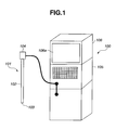
- Fig. 1 is an outline view showing an appearance of an electronic endoscope device
- Fig. 2 is a block diagram showing configuration of the electronic endoscope device in Fig. 1
- Fig. 3 is a diagram showing transmission characteristics of a light quantity limiting filter in Fig. 2
- Fig. 4 is a diagram showing arrangement of color filters provided on a front surface of a CCD in Fig. 2
- Fig. 5 is a diagram illustrating a matrix calculation method of calculating a matrix in a matrix operation portion in Fig. 2
- Fig. 6 is a diagram showing spectral characteristics of spectral images generated by the matrix operation portion in Fig. 2
- Fig. 1 is an outline view showing an appearance of an electronic endoscope device
- Fig. 2 is a block diagram showing configuration of the electronic endoscope device in Fig. 1
- Fig. 3 is a diagram showing transmission characteristics of a light quantity limiting filter in Fig
- FIG. 7 is a diagram showing a structure in a layer direction of living tissue observed by an electronic endoscope device in Fig. 2 ;
- Fig. 8 is a diagram illustrating a state of illumination light from the electronic endoscope device in Fig. 2 reaching living tissue in the layer direction;
- Fig. 9 is a diagram showing spectral characteristics of each band of RGB light during normal observation by the electronic endoscope device in Fig. 2 ;
- Fig. 10 is a first diagram showing a band image with RGB light during the normal observation in Fig. 9 .
- Fig. 11 is a second diagram showing a band image with RGB light during the normal observation in Fig. 9 ;
- Fig. 12 is a third diagram showing a band image with RGB light during the normal observation in Fig. 9 ;
- Fig. 13 is a first diagram showing one of the spectral images in Fig. 6 ;
- Fig. 14 is a second diagram showing one of the spectral images in Fig. 6 ;
- Fig. 15 is a third diagram showing one of the spectral images in Fig. 6 ;
- Fig. 16 is a first diagram illustrating a graphic user interface with a function of a touch-sensitive panel in Fig. 2 ;
- Fig. 17 is a second diagram illustrating the graphic user interface with the function of the touch-sensitive panel in Fig.
- Fig. 18 is a third diagram illustrating the graphic user interface with the function of the touch-sensitive panel in Fig. 2 ;
- Fig. 19 is a fourth diagram illustrating the graphic user interface with the function of the touch-sensitive panel in Fig. 2 ;
- Fig. 20 is a fifth diagram illustrating the graphic user interface with the function of the touch-sensitive panel in Fig. 2 .
- Fig. 21 is a sixth diagram illustrating the graphic user interface with the function of the touch-sensitive panel in Fig. 2 ;
- Fig. 22 is a seventh diagram illustrating the graphic user interface with the function of the touch-sensitive panel in Fig. 2 ;
- Fig. 23 is an eighth diagram illustrating the graphic user interface with the function of the touch-sensitive panel in Fig. 2 ;
- Fig. 24 is a ninth diagram illustrating the graphic user interface with the function of the touch-sensitive panel in Fig. 2 ;
- Fig. 25 is a tenth diagram illustrating the graphic user interface with the function of the touch-sensitive panel in Fig. 2 ;
- Fig. 26 is an eleventh diagram illustrating the graphic user interface with the function of the touch-sensitive panel in Fig. 2 ;
- Fig. 21 is a sixth diagram illustrating the graphic user interface with the function of the touch-sensitive panel in Fig. 2 ;
- Fig. 22 is a seventh diagram illustrating the graphic user interface with the function of the touch-
- FIG. 27 is a twelfth diagram illustrating the graphic user interface with the function of the touch-sensitive panel in Fig. 2 ;
- Fig. 28 is a diagram illustrating white balance processing on a spectral image generated by the matrix operation portion in Fig. 2 ;
- Fig. 29 is a thirteenth diagram illustrating the graphic user interface with the function of the touch-sensitive panel in Fig. 2 ;
- Fig. 30 is a fourteenth diagram illustrating the graphic user interface with the function of the touch-sensitive panel in Fig. 2 .
- Fig. 31 is a diagram showing configuration of board slots on a back surface of a main body of the endoscope device in Fig. 1 ;
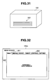
- Fig. 32 is a first diagram illustrating an additional function menu of a function expansion substrate inserted into a board slot in Fig. 31 ;
- Fig. 33 is a second diagram illustrating an additional function menu of a function expansion substrate inserted into the board slot in Fig. 31 ;
- Fig. 34 is a third diagram illustrating an additional function menu of a function expansion substrate inserted into the board slot in Fig. 31 ;
- Fig. 35 is a diagram showing one example of a keyboard dedicated to wavelength selection that can be connected to the main body of the endoscope device in Fig. 2 ; and
- Fig. 36 is a diagram showing arrangement in a variation of the color filters in Fig. 4 ;
- an electronic endoscope device as a living body observation device according to the embodiment of the present invention
- light is radiated to a living body being a subject from an illuminating light source
- a solid-state image pickup device being an image pickup portion receives light reflected from the living body based on the radiated light, photoelectrically converts the received light, so that a image pickup signal being a color image signal is generated and a spectral image signal (hereinafter, also simply referred to as a spectral image) being a spectral signal is generated corresponding to an optical wavelength narrowband image from the image pickup signal by signal processing.
- a spectral image signal hereinafter, also simply referred to as a spectral image
- an electronic endoscope device 100 includes an endoscope 101 as an observation portion, a main body 105 of the endoscope device and a display monitor 106 as a display device.
- the endoscope 101 is configured mainly with an insertion portion 102 inserted into a subject body, a distal end portion 103 provided at a distal end of the insertion portion 102, and an angle operation portion 104, being provided on an opposite side of the distal end of the insertion portion 102, for instructing bending operation on the distal end portion 103, for example.
- pre-determined signal processing is performed on an image of the subject acquired by the endoscope 101 being a flexible scope, and the display monitor 106 displays a processed image.
- a display portion of the display monitor 106 is provided with a touch-sensitive panel 106a, which realizes a graphic interface to display various setting screens on the display portion of the display monitor 106, and use a pointing device function of the touch-sensitive panel 106a (hereinafter, referred to as a touch-sensitive panel function).
- FIG. 2 is a block diagram of the electronic endoscope device 100.
- the main body 105 of the endoscope device is configured mainly with a light source portion 41 as an illumination portion, a control portion 42 as a signal processing control portion, and a main body processing device 43.
- the control portion 42 and the main body processing device 43 configure a signal processing control portion for controlling operation of the light source portion 41 and/or a CCD 21 as an image pickup portion, outputting an image signal to the display monitor 106 being a display device, and controlling a touch-sensitive panel function of the touch-sensitive panel 106a.
- the control portion 42 is connected to a data storage portion 44 for storing various data.
- the main body 105 of the endoscope device being a single unit includes the light source portion 41 and the main body processing device 43 for image processing, for example.
- the light source portion 41 and the main body processing device 43 can be also configured to be removable as separate units from the main body 105 of the endoscope device.
- the light source portion 41 being an illumination portion, which is connected to the control portion 42 and the endoscope 101, radiates a pre-determined light quantity of white light (which can be incomplete white light) based on a signal from the control portion 42.
- the light source portion 41 includes a lamp 15 as a white light source, an infrared cut filter 15a, a light quantity limiting filter 16, being inserted/removed on an optical path, as a spectral characteristics control portion for limiting light quantity in a pre-determined wavelength region of white light, a filter insertion/removal driving portion 17 for inserting/removing the light quantity limiting filter 16 on an optical path, and a condensing lens 18 for outputting white light.
- Fig. 3 shows transmission characteristics of the light quantity limiting filter 16. For example, when a transmission rate of a blue band is 100 %, the light quantity limiting filter 16 limits transmission rates of other bands to 50 %, as shown in Fig. 3 .
- the endoscope 101 connected to the light source portion 41 via a connector 11 comprises an object lens 19 and a solid-state image pickup device 21 such as a CCD (hereinafter, simply referred to as a CCD) at the distal end portion 103.
- the CCD 21 according to the present embodiment is a single-panel type (a CCD used for a simultaneous type electronic endoscope) and a primary color type.
- Fig. 4 shows arrangement of color filters arranged on an image pickup surface of the CCD 21. The color filters arranged on the image pickup surface of the CCD 21 configure a color separation portion.
- the insertion portion 102 contains a light guide 14 for guiding light radiated from the light source portion 41 to the distal end portion 103, a signal line for transmitting an image of a subject obtained by the CCD 21 to the main body processing device 43, a forceps channel 28 for treatment and the like.
- a forceps hole 29 for inserting forceps into the forceps channel 28 is provided in a vicinity of the operation portion 104.
- the operation portion 104 contains an ID portion 110 for storing classification information of the endoscope 101.
- the operation portion 104 is also provided with an instruction switch portion 111 for instructing various operations on an outer surface.
- the instruction switch portion 111 includes at least a mode changing switch for instructing a spectral image generation mode, which will be described later, to generate a spectral image with improved S/N.
- the main body processing device 43 as a signal processing device for a living body observation device is connected to the endoscope 101 via the connector 11 similarly to the light source portion 41.
- the main body processing device 43 contains a CCD drive 431 for driving the CCD 21 in the endoscope 101.
- the main body processing device 43 also includes a luminance signal processing system and a color signal processing system as signal circuit systems for obtaining a color image being a normal image.
- the luminance signal processing system of the main body processing device 43 includes a contour correction portion 432, being connected to the CCD 21, for correcting a contour of an image pickup signal from the CCD 21, and a luminance signal processing portion 434 for generating a luminance signal from data corrected by the contour correction portion 432.
- the color signal processing system of the main body processing device 43 also includes sample hold circuits (S/H circuits) 433a to 433c, being connected to the CCD 21, for sampling an image pickup signal obtained by the CCD 21, for example, to generate an RGB signal, and a color signal processing portion 435, being connected to outputs of the S/H circuits 433a to 433c, for generating a color signal.
- S/H circuits sample hold circuits
- the main body processing device 43 also includes a normal image generation portion 437 for generating a color image being a single normal image from the outputs of the luminance signal processing system and the color signal processing system.
- the normal image generation portion 437 outputs a Y signal being a luminance signal and an R-Y signal and a B-Y signal being color difference signals to a display image generation portion 439, and generates a normal image signal of a color image being a normal image displayed on the display monitor 106 by the display image generation portion 439 based on the Y signal, R-Y signal and B-Y signal.
- the main body processing device 43 includes a matrix operation portion 436 as a spectral signal generation portion for performing a pre-determined matrix operation on an RGB signal to which, as a signal circuit system for obtaining a spectral image signal being a spectral signal, outputs (RGB signals) of the S/H circuits 433a to 433c are inputted.
- the matrix operation by the matrix operation portion 436 is processing to perform addition processing, for example, on color image signals, and multiply a matrix obtained by a matrix calculation method described later.
- a method using electronic circuit processing (processing by hardware with an electronic circuit) will be described as a method for the matrix operation.
- a method can be also possible using numerical data processing (processing by software with a program).
- a combination of the methods is also possible.
- Spectral image signals F1 to F3 being output of the matrix operation portion 436 are subjected to color adjustment operation in a color adjustment portion 440 being a color adjustment portion to generate spectral color channel image signals Rch, Gch and Bch from the spectral image signals F1 to F3.
- the generated spectral color channel image signals Rch, Gch and Bch are sent to RGB color channels R-(ch), G-(ch) and B-(ch) of the display monitor 106 via the display image generation portion 439.
- the display image generation portion 439 generates a display image including a normal image and/or a spectral image and outputs the display image on the display monitor 106, and can display spectral images by switching between the images. That is, an operator can selectively display any of a normal image, a spectral color channel image through the color channel R-(ch), a spectral color channel image through the color channel G-(ch) and a spectral color channel image through the color channel B-(ch) on the display monitor 106.
- the display monitor 106 can also be configured to be able to simultaneously display any two or more images.
- a normal image and a spectral color channel image (hereinafter, also referred to as a spectral channel image) can be simultaneously displayed, a normal image for general observation and a spectral channel image can be easily compared, so that observation is possible in consideration of their respective features (a normal image has a feature of a color degree being similar to normal macroscopic observation and can be observed easily; and a spectral channel image has a feature that a pre-determined blood vessel, for example, can be observed that cannot be observed with a normal image), which is very useful to diagnosis.
- the following will describe a matrix calculation method for the matrix operation portion 436 to calculate a matrix.
- Fig. 5 is a conceptual diagram showing a flow of a signal in generating a spectral image signal corresponding to an image being more approximately equivalent to an optical wavelength narrowband image from color image signals (referred to as R, G and B herein for ease of description; however, combination of G, Cy, Mg and Ye is also possible in a complementary solid-state image pickup device, as described later).
- R, G and B optical wavelength narrowband image from color image signals
- a vector and a matrix are represented in a bold character or with " "(for example, a matrix A is represented as "A (bold character)", or "A"), while others are represented without character decoration.
- the electronic endoscope device 100 converts color sensitivity characteristics as spectral sensitivity characteristics of respective R, G and B image pickup portions into numerical data.
- the R, G and B color sensitivity characteristics are output characteristics for wavelengths obtained when an image of a white shooting object is picked up using a white-light source.
- the respective R, G and B color sensitivity characteristics are shown in right of image data as a simplified graph.
- the R, G and B color sensitivity characteristics are represented as n-dimensional column vectors "R", "G” and "B", respectively.
- the electronic endoscope device 100 converts a left-hand side of the expression (3) for the matrix "A" obtained by the expression (5) and can approximate characteristics of the narrowband bandpass filters F1, F2 and F3 to be extracted.
- the matrix operation portion 436 generates a spectral image signal from a normal color image signal using the matrix calculated as the above.
- the condensed light flux is radiated into a body of a subject from an illumination optical system provided at the distal end portion 103 through the light guide 14.
- the radiated light flux reflects in the subject and signals are collected for each color filter shown in Fig. 4 in the CCD 21 via the object lens 19.
- the collected signals are inputted to the above luminance signal processing system and color signal processing system in parallel.
- the signals collected for each color filter are added and inputted to the contour correction portion 432 of the luminance signal system for each pixel, and inputted to the luminance signal processing portion 434 after contour correction.
- Luminance signals are generated in the luminance signal processing portion 434, and inputted to the normal image generation portion 437.
- the signals collected by the CCD 21 are inputted to the S/H circuits 433a to 433c for each filter, and R, G and B signals are generated. Further, the color signal processing portion 435 generates color signals from the R, G and B signals.
- the normal image generation portion 437 generates Y signals, R-Y signals and B-Y signals from the luminance signals and color signals.
- the display image generation portion 439 displays a normal image of the subject on the display monitor 106.
- the spectral image generation mode can be also set to the second spectral image generation mode by operating a keyboard or the touch-sensitive panel 106a provided on the main body 105 instead of the mode changing switch of the instruction switch portion 111.
- the first spectral image generation mode and the second spectral image generation mode are same in other operation, so the description will take the first spectral image generation mode as an example. Similar operation to the normal image generation will not be described.
- the matrix operation portion 436 amplifies and adds outputs (RGB signals) of the S/H circuits 433a to 433c.
- the color adjustment portion 440 performs color adjustment operation on the spectral image signals F1 to F3 being outputs of the matrix operation portion 436 and the spectral color channel image signals Rch, Gch and Bch are generated from the spectral image signals F1 to F3.
- the generated spectral color channel image signals Rch, Gch and Bch are sent to the RGB color channels R-(ch), G-(ch) and B-(ch) of the display monitor 106.
- the main body processing device 43 can display a spectral image corresponding to a narrowband light observation image obtained with narrowband light via narrowband bandpass filters F1, F2 and F3 with center wavelengths ⁇ 1, ⁇ 2 and ⁇ 3 as shown in Fig. 6 on the display monitor 106.
- the following illustrates one example of a spectral image generated using the quasi-filter characteristics corresponding to the narrowband bandpass filters F1, F2 and F3.
- tissue in a body cavity 51 often has absorber distribution structures such as different blood vessels in a depth direction, for example.
- Many capillary vessels 52 distribute around a mucosa surface layer
- blood vessels 53 which are larger than the capillary vessels, distribute in addition to the capillary vessels in an intermediate layer being deeper than the mucosa surface layer
- further larger blood vessels 54 distribute in a further deeper layer.
- an invasion depth of light in a depth direction into the tissue in the body cavity 51 depends on a wavelength of the light.
- short wavelength light like blue (B) light as shown in Fig. 8 only invades near a surface layer due to absorption characteristics and scattering characteristics in living tissue, is absorbed and scattered in that depth range, and light emitted from the surface is observed.
- Green (G) light of a longer wavelength than blue (B) light invades deeper than the range in which blue (B) light invades, is absorbed and scattered in that range, and light emitted from the surface is observed.
- Red (R) light of a longer wavelength than green (G) light reaches a deeper range.
- the color adjustment portion 440 assigns the spectral image signal F3 to the spectral color channel image signal Rch, the spectral image signal F2 to the spectral color channel image signal Gch, and the spectral image signal F1 to the spectral color channel image signal Bch, as an example of simplest color conversion, and outputs the signals to the RGB color channels R-(ch), G-(ch) and B-(ch) of the display monitor 106 via the display image generation portion 439.
- a color image through the color channels R-(ch), G-(ch) and B-(ch) is observed on the display monitor 106, it appears as an image as shown in Fig. 16 , for example.
- Large blood vessels are at deeper positions, the spectral image signal F3 is reflected, and a color image having pre-determined target colors is shown as a red pattern.
- the spectral image signal F2 is strongly reflected, so that a color image having pre-determined target colors is shown as a magenta pattern.
- Some of the vascular networks near a mucosa surface are expressed as yellow patterns.
- the spectral image signals F1 to F3 depend on spectral sensitivity of an endoscope such as a lens or an opto-electric conversion system in addition to spectral reflectivity of a shooting object.
- the control portion 43 reads out an ID being classification information of the endoscope 101 from the ID portion 110 in the operation portion 104, and corrects the spectral image signals F1 to F3 with a correction coefficient depending on the connected endoscope 101 stored in the data storage portion 44 based on the ID.
- the present embodiment can be configured such that a correction coefficient is stored in the ID portion 110 and the control portion 43 reads out an ID and the correction coefficient from the ID portion 110.
- the spectral image signals F1 to F3 are generated through matrices corresponding to the quasi-bandpass filters F1 to F3, while the quasi-bandpass filters F1 to F3 are characterized by center wavelengths ⁇ 1, ⁇ 2 and ⁇ 3. That is, the main body processing device 43 sets one center wavelength ⁇ to decide one quasi-bandpass filter F, and generates a spectral image signal F based on the quasi-bandpass filter F.
- a function of the touch-sensitive panel 106a can be used to set a center wavelength ⁇ by a graphic user interface and generate a desired spectral image signal F.
- the main body processing device 43 displays a setting screen to set a center wavelength of a quasi-bandpass filter corresponding to a spectral image signal on the observation monitor 106 including the touch-sensitive panel 106a as in Fig. 17 .
- the setting screen can set a plurality of, for example, six center wavelengths ⁇ 11, ⁇ 12, ⁇ 13, ⁇ 21, ⁇ 22 and ⁇ 23.
- the main body processing device 43 deploys and displays a pop-up window 207 having a plurality of selectable wavelengths on the observation monitor 106.
- a set wavelength value of the pop-up window 207 is selected through the touch-sensitive panel function, so that the main body processing device 43 sets the set wavelength value as the wavelength ⁇ 11.
- Fig. 17 indicates a state of the main body processing device 43 having set a set wavelength value 425 nm as the wavelength ⁇ 11.
- Operations to set other wavelengths i.e., a ⁇ 12 button 202, a ⁇ 13 button 203, a ⁇ 21 button 204, a ⁇ 22 button 205 and ⁇ 23 button 206 can also set wavelength values to be set using the touch-sensitive panel function on the setting screen similarly to the wavelength ⁇ 11.
- a spectral image can be colored by setting set wavelength values as at least three wavelengths (for example, the wavelengths ⁇ 11, ⁇ 12 and ⁇ 13) on the setting screen.
- a colored spectral image is referred to as a color spectral image.
- the setting screen to set a center wavelength of a quasi-bandpass filter is not limited to as shown in Fig. 17 , but can be a setting screen including a set table 208 to set a plurality of wavelength sets in which three wavelengths constitutes a set for previous coloring as shown in Fig. 18 as a first variation of the present embodiment. If the setting screen in Fig. 18 is displayed on the observation monitor 106 including the touch-sensitive panel 106a, a desired wavelength set can be selected from the plurality of wavelength sets being set in the set table 208 using the touch-sensitive panel function.
- a select button 209 can be provided, the set table 208 can be set by toggling the wavelength sets at each time the select button 209 is operated using the touch-sensitive panel function as shown in Fig. 19 as a second variation of the present embodiment. Specifically, each time the select button 209 is operated using the touch-sensitive panel function, a set to be set is toggled for selection as in set 1 ⁇ set 2 ⁇ set 3 ⁇ set 4 ⁇ set 1 ⁇ .... Fig. 20 shows the setting screen when the select button 209 is operated using the touch-sensitive panel function in the state in Fig. 19 , selection of the set 1 as shown in Fig. 19 shifts to selection of the set 2 as shown in Fig. 20 through an operation of the select button 209.
- the display image generation portion 439 has display forms to display a color spectral image on the display screen of the touch-sensitive panel 106a (i.e., the observation monitor 106) such as: (1) a display form to simultaneously display a normal light observation image and a color spectral image; (2) a display form to display only a color spectral image; and (3) a display form to display only a normal light observation image.
- the main body processing device 43 can simultaneously display a normal light observation image 210 and a colored color spectral image 211 on the observation monitor 106 by the display image generation portion 439, as shown in Fig. 21 .
- the display image generation portion 439 can display thumbnail images 221 to 226 of spectral images with the six center wavelengths being set in, for example, the above setting screen available to be used in coloring the color spectral image 211 in addition to the normal light observation image 210 and the color spectral image 211.
- thumbnail images of three spectral images configuring the color spectral image 211 are displayed in a different display form (for example, luminance or color tone) from other thumbnail images.
- three spectral images can be arbitrarily changed that configure the color spectral image 211 by selecting any of the thumbnail images 221 to 226 using the touch-sensitive panel function. Specifically, for example when the color spectral image 211 is touched, the thumbnail images 221 to 226 are selectable, and three spectral images are changed that configure the color spectral image 211 by selecting thumbnail images of spectral images with three center wavelengths for coloring.
- FIG. 21 shows a state of the color spectral image 211 being generated through three spectral images with the center the wavelengths ⁇ 11, ⁇ 12 and ⁇ 13.
- Fig. 22 shows a state of the color spectral image 211 being generated through three spectral images with the center wavelengths ⁇ 12, ⁇ 21 and ⁇ 23.
- the main body processing device 43 can display a painting setting window 230 to change a color tone of the normal light image by superposition.
- the device 43 can change the color tone of the normal light image by the user touching an indicator 230a of the painting setting window 203 using the touch-sensitive panel function to change a ratio of red to blue.
- the painting setting window 203 is available as a wavelength selection window 230 for a center wavelength ⁇ , as shown in Fig. 24 .
- the indicator 230a shows wavelengths
- each display point of the indicator 230a is assigned with a plurality of center wavelengths
- three spectral images configuring the color spectral image 211 can be selected in the wavelength selection window 230 by selecting three display points in the indicator 230a.
- a luminance setting window 231 to set luminance of a spectral image is displayed below the wavelength selection window 230, so that luminance of a spectral image with each wavelength can be arbitrarily set.
- the main body processing device 43 can display spectral reflectivity 242 from a subject in a vicinity of a color spectral image 241 as a graph, as shown in Fig. 25 .
- the wavelengths ⁇ 1, ⁇ 2 and ⁇ 3 of three spectral images configuring the color spectral image 241 are presented on the spectral reflectivity 242, the wavelengths ⁇ 1, ⁇ 2 and ⁇ 3 can vary through the touch-sensitive panel function; when the wavelengths ⁇ 1, ⁇ 2 and ⁇ 3 vary, the three spectral images configuring the color spectral image 241 change accordingly.
- a freeze switch (not shown) of the instruction switch portion 111 provided in the operation portion 104 of the endoscope 101, for example, is operated in the display form to display only a color spectral image
- a color spectral image being displayed as a moving image becomes the static freeze color spectral image 241, as shown in Fig. 26 .
- the main body processing device 43 displays thumbnail images 221 to 226 of the spectral images with the six center wavelengths being set in, for example, the above setting screen available to be used in coloring the freeze color spectral image 241 in a vicinity of the freeze color spectral image 241.
- the thumbnail images of the three spectral images configuring the freeze color spectral image 241 are displayed in a different display form (for example, different luminance or color tone) from other thumbnail images.
- three spectral images configuring the freeze color spectral image 241 can be arbitrarily changed by selecting the thumbnail images 221 to 226 using the touch-sensitive panel function and operating a selection decision button 243 as shown in Fig. 27 .
- the color spectral image 241 of a moving image of the three spectral images selected from the thumbnail images 221 to 226 can be displayed by operating a confirmation button 244 using the touch-sensitive panel function.
- the color spectral image 241 of the moving image of the three spectral images selected from the thumbnail images 221 to 226 can also be automatically displayed only by an operation of the selection decision button 243, instead of providing the confirmation button 244.
- the main body 105 of the endoscope device can arbitrarily change three spectral images configuring a color spectral image. In that case, white balance processing for the three spectral images is changed simultaneously.
- the main body 105 of the endoscope device discretely stores a three-dimensional data table with three wavelengths ⁇ i, ⁇ j and ⁇ k as axes as shown in Fig. 28 previously in the data storage portion 44, for example.
- Each voxel of the three-dimensional data table stores weighting factors (kx, ky, kz) used for the white balance processing as voxel data.
- the main body 105 of the endoscope device discretely stores the three-dimensional data table to reduce a storage capacity of the data storage portion 44 for storing respective voxel data.
- the weighting factors among the voxel data are calculated through general linear interpolation for the white balance processing.
- the main body processing device 43 designates a spectral image display frame 281 on the normal light observation image 210 as shown in Fig. 29 , so that the device 43 can display a spectral image of the region by superposition in a region of the designated spectral image display frame 281.
- a size and position of the spectral image display frame 281 can be arbitrarily changed by the touch-sensitive panel function, as shown in Fig. 30 .
- configuration of a spectral image is set using a wavelength as a setting parameter, but the present invention is not limited thereto. Instead, the designation can be done using depth information being an invasion depth of light as a setting parameter, or the designation can be done using a function name such as blood vessel highlighting as a setting parameter.
- a method of designating configuration of a spectral image based on an organ includes a method of identifying and designating an organ for which the endoscope 101 is used with an ID from the ID portion 110 in the operation portion 104, a method of designating by a menu switch on the touch-sensitive panel 106a, a method of designating by reading data of a PC card recording patient information, or a method of automatically recognizing an organ by performing image processing on a normal light observation image by a scene understanding module, for example.
- the main body 105 of the endoscope device according to the present embodiment is provided with a plurality of board slots 300 on a back surface into which function expansion substrates for function expansion can be inserted, as shown in Fig. 31 .
- the control portion 44 displays a menu window 260 as shown in Fig. 32 on the touch-sensitive panel 106a to deploy executable functions.
- default functions of the control portion 44 without a function expansion substrate being inserted can be classified to four basic functions, for example, the functions are switchable using tags 261 of menus 1, 2, 3 and 4 on the menu window 260.
- the menu window 260 includes menu tags 262 for a plurality of function expansion substrates in addition to the tags 261 of menus 1, 2, 3 and 4.
- the menu tags 262 are for empty menus, as shown in Fig. 33 .
- the control portion 44 can deploy an additional function menu window of functions of the inserted function expansion substrate from the menu window 260 through a tag 262a of a menu 5, as shown in Fig. 34 .
- the additional function menu window is configured in software. As such, when a function expansion substrate is inserted, the control portion 44 identifies the function expansion substrate, and a menu window with similar configuration to the basic functions is automatically generated, so that a version of software does not need to be changed, or a version of the software is easily upgraded.
- the operation is performed through the touch-sensitive panel 106a, and specifications can be easily changed without changing hardware, but by upgrading a version of the software.
- a wavelength setting function can be assigned to a function key of a general keyboard.
- the display monitor 106 in a default state of a spectral image generation mode being the first spectral image generation mode, can selectively display a normal light observation image and a spectral image by prioritizing a image quality of a normal light observation image. Further, the mode changing switch of the instruction switch portion 111 switches the spectral image generation mode to the second spectral image generation mode through operation, transmit light flux from the lamp 15 through the light quantity limiting filter 16, and decreases light quantity of light in other wavelength bands to a half of light in a blue wavelength band, so that the display monitor 106 can selectively display the normal light observation image and the spectral image by prioritizing image quality of a spectral image.
- a spectral image in a blue wavelength band can be improved to image information with a similar S/N to spectral images in other wavelength bands, for example.
- the light quantity limiting filter 16 is configured to be insertably removable on an optical path.
- the filter 16 can also be permanently provided on an optical path.
- a color filter provided for the CCD 21 can have similar spectral characteristics to a light quantity limiting filter, thereby omitting the light quantity limiting filter 16.
- complementary color filters can be used instead of using the RGB primary color filters.
- Arrangement of the complementary filters is configured with G, Mg, Ye and Cy elements as shown in Fig. 36 .
- the S/H circuit shown in Fig. 2 is not for R, G and B, but for G, Mg, Cy and Ye, but living body spectral reflectivity can be approximated with three basic spectral characteristics for four or less portions. Accordingly, a dimension to calculate an estimated matrix is changed from three to four.
- Figs. 37 to 43 relate to a second embodiment of the present invention.
- Fig. 37 is a block diagram showing configuration of an electronic endoscope device;
- Fig. 38 is a diagram showing configuration of an RGB rotating filter in Fig. 37 ;
- Fig. 39 is a diagram showing spectral characteristics of light that is transmitted through the RGB rotating filter in Fig. 38 when a light quantity limiting filter in a first spectral image generation mode is not on an optical path;
- Fig. 40 is a diagram showing spectral characteristics of light that is transmitted through the RGB rotating filter in Fig. 38 when the light quantity limiting filter in a second spectral image generation mode is on an optical path;
- Fig. 41 is a block diagram showing configuration of a variation of the electronic endoscope device in Fig. 37 ;
- Fig. 42 is a diagram showing configuration of an RGB rotating filter in Fig. 41 ;
- Fig. 43 is a diagram showing configuration of a variation of the RGB rotating filter in Fig. 38 .
- the second embodiment is almost same as the first embodiment. As such, only different points will be described and the same components are given same numerals and will not be described.
- the present embodiment differs from the first embodiment mainly in the light source portion 41 and the CCD 21.
- the CCD 21 is provided with the color filter shown in Fig. 4 , and a so-called simultaneous type is used in which the color filter generates a color signal.
- so-called frame sequential type is used for illuminating illumination light in an RGB order to generate a color signal.
- the light source portion 41 in the light source portion 41 according to the present embodiment, light via the lamp 15, the infrared cut filter 15a and the light quantity limiting filter 16 is transmitted through an RGB filter 23.
- the light quantity limiting filter 16 is insertably removable on an optical path.
- the RGB rotating filter 23 is configured with an R filter portion 23r for transmitting R band light, a G filter portion 23g for transmitting G band light, and a B filter portion 23b for transmitting B band light, as shown in Fig. 38.
- Fig. 39 shows spectral characteristics of light transmitting the RGB rotating filter 23 in the first spectral image generation mode, i.e., when the light quantity limiting filter 16 is not on an optical path.
- Fig. 40 shows spectral characteristics of light being transmitted through the RGB rotating filter 23 in the second spectral image generation mode, i.e., when the light quantity limiting filter 16 is on an optical path.
- unnecessary infrared components of light flux outputted from the lamp 15 are cut in the infrared cut filter 15a, and light flux being transmitted through the infrared cut filter 15a selectively passes through the light quantity limiting filter 16 and is transmitted through the RGB rotating filter 23, so that the light flux is outputted from the light source portion as R, G and B illumination lights at each pre-determined time.
- the respective illumination lights reflect in a subject and received by the CCD 21.
- Signals obtained by the CCD 21 are distributed by a switch portion (not shown) provided for the main body 105 of the endoscope device depending on radiation time, and inputted to the S/H circuits 433a to 433c, respectively. That is, if illumination light is radiated from the light source portion 41 via an R filter, the signals obtained by the CCD 21 are inputted to the S/H circuit 433a.
- the other operation is similar to the first embodiment and will not be described.
- a spectral image in a blue wavelength band can be improved to image information with similar S/N of spectral images in other wavelength bands, for example.
- the light quantity limiting filter 16 is configured to be insertably removable on an optical path, but the embodiment is not limited thereto.
- the RGB rotating filter 23 can be configured as shown in Fig. 42 to omit the light quantity limiting filter 16 as shown in Fig. 41 .
- the rotating filter 23 is configured in a disc shape and has a double structure centering on a rotation axis as shown in Fig. 42 .
- an R filter portion 23r1 On an outside diameter part of the filter 23, an R filter portion 23r1, the G filter portion 23g1 and the B filter portion 23b1 are arranged that configure a first filter set to output frame sequential light with the spectral characteristics as shown in Fig. 39 .
- an R' filter portion 23r2, a G' filter portion 23g2 and a B filter portion 23b2 are arranged that configure a second filter set to output frame sequential light with the spectral characteristics as shown in Fig. 40 .
- control portion 42 controls driving of a rotating filter motor 26 and rotates the motor 26 as shown in Fig. 41 , and the control portion 42 moves the filter 23 in a diameter direction (moves perpendicularly to an optical path of the rotating filter 23, and selectively moves the first filter set or second filter set of the rotating filter 23 on the optical path) through a filter switch motor 17a.
- the rotating filter 23 can be a rotating filter for transmitting multiband (four or more bands) frame sequential lights 11, 12, 13 and 14 in four different bands as shown in Fig. 43 , for example, and for radiating multiband frame sequential lights.
- the expression (7) can generate a monochrome spectral image with a single wavelength from four band signals.
- the expression (8) can generate spectral images with four wavelengths from four band signals, and the display image generation portion 439 selects three of the four spectral images to generate a color spectral image.
- the above configuration to radiate multiband frame sequential light can estimate spectral images from four band signals, so that the spectral images can be estimated more accurately.
- the above configuration to radiate multiband frame sequential lights can realize multiband lights in different bands using a multicolor LED or LD.
Landscapes
- Health & Medical Sciences (AREA)
- Life Sciences & Earth Sciences (AREA)
- Surgery (AREA)
- Engineering & Computer Science (AREA)
- Physics & Mathematics (AREA)
- Optics & Photonics (AREA)
- Biomedical Technology (AREA)
- Veterinary Medicine (AREA)
- Biophysics (AREA)
- Pathology (AREA)
- Radiology & Medical Imaging (AREA)
- Nuclear Medicine, Radiotherapy & Molecular Imaging (AREA)
- Public Health (AREA)
- Heart & Thoracic Surgery (AREA)
- Medical Informatics (AREA)
- Molecular Biology (AREA)
- Animal Behavior & Ethology (AREA)
- General Health & Medical Sciences (AREA)
- Signal Processing (AREA)
- Multimedia (AREA)
- Astronomy & Astrophysics (AREA)
- General Physics & Mathematics (AREA)
- Endoscopes (AREA)
- Instruments For Viewing The Inside Of Hollow Bodies (AREA)
- Closed-Circuit Television Systems (AREA)
Applications Claiming Priority (2)
| Application Number | Priority Date | Filing Date | Title |
|---|---|---|---|
| JP2006073183A JP4951256B2 (ja) | 2006-03-16 | 2006-03-16 | 生体観測装置 |
| PCT/JP2007/053088 WO2007108270A1 (ja) | 2006-03-16 | 2007-02-20 | 生体観測装置 |
Publications (3)
| Publication Number | Publication Date |
|---|---|
| EP1994875A1 true EP1994875A1 (de) | 2008-11-26 |
| EP1994875A4 EP1994875A4 (de) | 2010-04-28 |
| EP1994875B1 EP1994875B1 (de) | 2013-12-18 |
Family
ID=38522306
Family Applications (1)
| Application Number | Title | Priority Date | Filing Date |
|---|---|---|---|
| EP07714591.0A Not-in-force EP1994875B1 (de) | 2006-03-16 | 2007-02-20 | Vorrichtung zur beobachtung eines lebenden körpers |
Country Status (7)
| Country | Link |
|---|---|
| US (1) | US8581970B2 (de) |
| EP (1) | EP1994875B1 (de) |
| JP (1) | JP4951256B2 (de) |
| KR (1) | KR101022585B1 (de) |
| CN (1) | CN101400294B (de) |
| BR (1) | BRPI0709580A2 (de) |
| WO (1) | WO2007108270A1 (de) |
Cited By (5)
| Publication number | Priority date | Publication date | Assignee | Title |
|---|---|---|---|---|
| EP2105086A1 (de) * | 2008-03-28 | 2009-09-30 | Fujifilm Corporation | Elektronisches Endoskopgerät |
| EP1880661A3 (de) * | 2006-07-21 | 2010-07-28 | FUJIFILM Corporation | Elektronisches Endoskopsystem |
| EP2258251A1 (de) * | 2009-06-05 | 2010-12-08 | Fujifilm Corporation | Verfahren und endoskopische Vorrichtung zum Erhalt eines Bildes |
| EP2862500A1 (de) * | 2013-09-27 | 2015-04-22 | Fujifilm Corporation | Endoskopsystem und Endoskopbetriebsverfahren |
| WO2016151062A1 (en) * | 2015-03-26 | 2016-09-29 | Koninklijke Philips N.V. | Device, system and method for illuminating a structure of interest inside a human or animal body |
Families Citing this family (40)
| Publication number | Priority date | Publication date | Assignee | Title |
|---|---|---|---|---|
| JP2009125411A (ja) * | 2007-11-27 | 2009-06-11 | Fujinon Corp | 内視鏡画像処理方法および装置ならびにこれを用いた内視鏡システム |
| JP5246643B2 (ja) * | 2007-12-19 | 2013-07-24 | 富士フイルム株式会社 | 撮像システムおよびプログラム |
| JP5039621B2 (ja) * | 2008-03-25 | 2012-10-03 | 富士フイルム株式会社 | 電子内視鏡装置 |
| JP5098030B2 (ja) * | 2008-04-02 | 2012-12-12 | 富士フイルム株式会社 | 撮像装置、撮像方法、およびプログラム |
| DK2291640T3 (en) | 2008-05-20 | 2019-03-11 | Univ Health Network | Device and method for fluorescence-based imaging and monitoring |
| JP5483522B2 (ja) * | 2008-08-12 | 2014-05-07 | 富士フイルム株式会社 | 画像取得装置 |
| JP2010051602A (ja) * | 2008-08-29 | 2010-03-11 | Fujifilm Corp | 電子内視鏡装置および方法並びにプログラム |
| JP5203861B2 (ja) * | 2008-09-10 | 2013-06-05 | 富士フイルム株式会社 | 内視鏡システム、およびその作動方法 |
| JP5127639B2 (ja) | 2008-09-10 | 2013-01-23 | 富士フイルム株式会社 | 内視鏡システム、およびその作動方法 |
| WO2010044446A1 (ja) * | 2008-10-17 | 2010-04-22 | オリンパス株式会社 | 画像生成装置、内視鏡システム、および画像生成方法 |
| CN102170817B (zh) | 2008-10-17 | 2014-03-19 | 奥林巴斯医疗株式会社 | 内窥镜系统和内窥镜图像处理装置 |
| JP2010213746A (ja) * | 2009-03-13 | 2010-09-30 | Fujifilm Corp | 内視鏡画像処理装置および方法ならびにプログラム |
| WO2010131687A1 (ja) | 2009-05-12 | 2010-11-18 | オリンパスメディカルシステムズ株式会社 | 被検体内撮像システムおよび被検体内導入装置 |
| JP5460506B2 (ja) | 2009-09-24 | 2014-04-02 | 富士フイルム株式会社 | 内視鏡装置の作動方法及び内視鏡装置 |
| JP5460507B2 (ja) * | 2009-09-24 | 2014-04-02 | 富士フイルム株式会社 | 内視鏡装置の作動方法及び内視鏡装置 |
| JP5541914B2 (ja) | 2009-12-28 | 2014-07-09 | オリンパス株式会社 | 画像処理装置、電子機器、プログラム及び内視鏡装置の作動方法 |
| CN106377223B (zh) * | 2010-02-10 | 2019-01-04 | Hoya株式会社 | 电子内窥镜系统 |
| US9420153B2 (en) | 2010-02-10 | 2016-08-16 | Hoya Corporation | Electronic endoscope system |
| JP5393534B2 (ja) * | 2010-02-26 | 2014-01-22 | Hoya株式会社 | 電子内視鏡装置 |
| JP5385188B2 (ja) * | 2010-03-26 | 2014-01-08 | 富士フイルム株式会社 | 電子内視鏡システム |
| JP5507376B2 (ja) * | 2010-07-28 | 2014-05-28 | 三洋電機株式会社 | 撮像装置 |
| JP5133386B2 (ja) * | 2010-10-12 | 2013-01-30 | 富士フイルム株式会社 | 内視鏡装置 |
| JP5639464B2 (ja) * | 2010-12-21 | 2014-12-10 | 富士フイルム株式会社 | 光計測システムおよび光計測システムの作動方法 |
| JP5649947B2 (ja) * | 2010-12-21 | 2015-01-07 | 富士フイルム株式会社 | 光計測システムおよび光計測システムの作動方法 |
| JP5554253B2 (ja) * | 2011-01-27 | 2014-07-23 | 富士フイルム株式会社 | 電子内視鏡システム |
| JP5274591B2 (ja) * | 2011-01-27 | 2013-08-28 | 富士フイルム株式会社 | 内視鏡システム、内視鏡システムのプロセッサ装置、及び内視鏡システムの作動方法 |
| JP5550574B2 (ja) * | 2011-01-27 | 2014-07-16 | 富士フイルム株式会社 | 電子内視鏡システム |
| US20130113904A1 (en) * | 2011-11-08 | 2013-05-09 | Capso Vision, Inc. | System and Method for Multiple Viewing-Window Display of Computed Spectral Images |
| JP5863435B2 (ja) * | 2011-12-15 | 2016-02-16 | Hoya株式会社 | 画像信号処理装置 |
| JP5872916B2 (ja) * | 2012-01-25 | 2016-03-01 | 富士フイルム株式会社 | 内視鏡システム、内視鏡システムのプロセッサ装置、及び内視鏡システムの作動方法 |
| JP5959987B2 (ja) * | 2012-08-15 | 2016-08-02 | Hoya株式会社 | 内視鏡システム |
| JP2014128394A (ja) * | 2012-12-28 | 2014-07-10 | Hoya Corp | 内視鏡装置 |
| KR101941907B1 (ko) * | 2013-01-03 | 2019-01-24 | 삼성전자주식회사 | 깊이 정보를 이용하는 내시경 및 깊이 정보를 이용하는 내시경에 의한 용종 검출 방법 |
| CN103284681A (zh) * | 2013-05-24 | 2013-09-11 | 中国科学院苏州生物医学工程技术研究所 | 一种血管内双光谱成像装置 |
| CN106163372B (zh) * | 2014-03-31 | 2018-11-20 | 富士胶片株式会社 | 内窥镜系统及其工作方法 |
| WO2016011534A1 (en) | 2014-07-24 | 2016-01-28 | University Health Network | Collection and analysis of data for diagnostic purposes |
| JP6606817B2 (ja) * | 2014-09-26 | 2019-11-20 | セイコーエプソン株式会社 | 測定装置 |
| CN105306896B (zh) * | 2015-10-27 | 2018-07-10 | 杭州永控科技有限公司 | 基于光定位的案件卷宗移交方法及系统 |
| JP6133474B2 (ja) * | 2016-06-21 | 2017-05-24 | Hoya株式会社 | 内視鏡システム |
| WO2019171703A1 (ja) | 2018-03-05 | 2019-09-12 | オリンパス株式会社 | 内視鏡システム |
Family Cites Families (11)
| Publication number | Priority date | Publication date | Assignee | Title |
|---|---|---|---|---|
| GB2068537B (en) * | 1980-02-04 | 1984-11-14 | Energy Conversion Devices Inc | Examining biological materials |
| US5751672A (en) | 1995-07-26 | 1998-05-12 | Sony Corporation | Compact disc changer utilizing disc database |
| EP2319390B1 (de) | 2000-07-21 | 2016-04-20 | Olympus Corporation | Endoskop |
| JP3583731B2 (ja) * | 2000-07-21 | 2004-11-04 | オリンパス株式会社 | 内視鏡装置および光源装置 |
| US6678398B2 (en) * | 2000-09-18 | 2004-01-13 | Sti Medical Systems, Inc. | Dual mode real-time screening and rapid full-area, selective-spectral, remote imaging and analysis device and process |
| JP2003093336A (ja) * | 2001-09-26 | 2003-04-02 | Toshiba Corp | 電子内視鏡装置 |
| US7252633B2 (en) * | 2002-10-18 | 2007-08-07 | Olympus Corporation | Remote controllable endoscope system |
| JP4294440B2 (ja) | 2003-10-30 | 2009-07-15 | オリンパス株式会社 | 画像処理装置 |
| JP4598178B2 (ja) * | 2003-12-25 | 2010-12-15 | Hoya株式会社 | 電子内視鏡用プロセッサ、及び電子内視鏡システム |
| JP2005198750A (ja) * | 2004-01-14 | 2005-07-28 | Pentax Corp | プロセッサおよび電子内視鏡システム |
| JP2005296200A (ja) * | 2004-04-08 | 2005-10-27 | Olympus Corp | 内視鏡用画像処理装置 |
-
2006
- 2006-03-16 JP JP2006073183A patent/JP4951256B2/ja not_active Expired - Fee Related
-
2007
- 2007-02-20 WO PCT/JP2007/053088 patent/WO2007108270A1/ja not_active Ceased
- 2007-02-20 CN CN2007800084664A patent/CN101400294B/zh not_active Expired - Fee Related
- 2007-02-20 EP EP07714591.0A patent/EP1994875B1/de not_active Not-in-force
- 2007-02-20 BR BRPI0709580-5A patent/BRPI0709580A2/pt not_active IP Right Cessation
- 2007-02-20 KR KR1020087022311A patent/KR101022585B1/ko not_active Expired - Fee Related
-
2008
- 2008-09-15 US US12/210,672 patent/US8581970B2/en active Active
Cited By (7)
| Publication number | Priority date | Publication date | Assignee | Title |
|---|---|---|---|---|
| EP1880661A3 (de) * | 2006-07-21 | 2010-07-28 | FUJIFILM Corporation | Elektronisches Endoskopsystem |
| US8269824B2 (en) | 2006-07-21 | 2012-09-18 | Fujifilm Corporation | Electronic endoscope system for estimating and producing spectral image of arbitrary wavelength band from image signals captured under general illumination light and those captured under specific illumination light |
| EP2105086A1 (de) * | 2008-03-28 | 2009-09-30 | Fujifilm Corporation | Elektronisches Endoskopgerät |
| EP2258251A1 (de) * | 2009-06-05 | 2010-12-08 | Fujifilm Corporation | Verfahren und endoskopische Vorrichtung zum Erhalt eines Bildes |
| EP2862500A1 (de) * | 2013-09-27 | 2015-04-22 | Fujifilm Corporation | Endoskopsystem und Endoskopbetriebsverfahren |
| US9794494B2 (en) | 2013-09-27 | 2017-10-17 | Fujifilm Corporation | Endoscope system and method with pixel gain correction |
| WO2016151062A1 (en) * | 2015-03-26 | 2016-09-29 | Koninklijke Philips N.V. | Device, system and method for illuminating a structure of interest inside a human or animal body |
Also Published As
| Publication number | Publication date |
|---|---|
| CN101400294A (zh) | 2009-04-01 |
| JP4951256B2 (ja) | 2012-06-13 |
| JP2007244681A (ja) | 2007-09-27 |
| EP1994875B1 (de) | 2013-12-18 |
| EP1994875A4 (de) | 2010-04-28 |
| US20090040298A1 (en) | 2009-02-12 |
| KR20080095280A (ko) | 2008-10-28 |
| BRPI0709580A2 (pt) | 2011-07-19 |
| CN101400294B (zh) | 2011-03-02 |
| US8581970B2 (en) | 2013-11-12 |
| KR101022585B1 (ko) | 2011-03-16 |
| WO2007108270A1 (ja) | 2007-09-27 |
Similar Documents
| Publication | Publication Date | Title |
|---|---|---|
| EP1994875B1 (de) | Vorrichtung zur beobachtung eines lebenden körpers | |
| EP1880658B1 (de) | Signalaufbereitungsvorrichtung für ein biologisches beobachtungsgerät | |
| RU2381737C2 (ru) | Устройство для наблюдения биологических объектов | |
| JP5977772B2 (ja) | 内視鏡システム、内視鏡システムのプロセッサ装置、内視鏡システムの作動方法、プロセッサ装置の作動方法 | |
| US10335014B2 (en) | Endoscope system, processor device, and method for operating endoscope system | |
| JP4504324B2 (ja) | 生体観測装置 | |
| JP5869541B2 (ja) | 内視鏡システム及びプロセッサ装置並びに内視鏡システムの作動方法 | |
| KR100988113B1 (ko) | 생체 관측 장치 | |
| US10003774B2 (en) | Image processing device and method for operating endoscope system | |
| JP6054806B2 (ja) | 画像処理装置及び内視鏡システムの作動方法 | |
| CN104939791B (zh) | 医用图像处理装置及其工作方法 | |
| JP7080195B2 (ja) | 内視鏡システム | |
| JP2010213992A (ja) | 内視鏡システム、内視鏡用プロセッサ装置、並びに内視鏡駆動方法 | |
| US20140253580A1 (en) | Image processing device and method for operating endoscope system | |
| US10285631B2 (en) | Light source device for endoscope and endoscope system | |
| JPWO2018142658A1 (ja) | 内視鏡システム | |
| US10278628B2 (en) | Light source device for endoscope and endoscope system | |
| CN112584746A (zh) | 医用图像处理装置和内窥镜系统以及医用图像处理装置的工作方法 | |
| US11490798B2 (en) | Endoscope system, endoscope apparatus, light source apparatus, and method of operating endoscope system | |
| JP2018051364A (ja) | 内視鏡システム、内視鏡システムのプロセッサ装置、内視鏡システムの作動方法、プロセッサ装置の作動方法 | |
| JP6272956B2 (ja) | 内視鏡システム、内視鏡システムのプロセッサ装置、内視鏡システムの作動方法、プロセッサ装置の作動方法 |
Legal Events
| Date | Code | Title | Description |
|---|---|---|---|
| PUAI | Public reference made under article 153(3) epc to a published international application that has entered the european phase |
Free format text: ORIGINAL CODE: 0009012 |
|
| 17P | Request for examination filed |
Effective date: 20080915 |
|
| AK | Designated contracting states |
Kind code of ref document: A1 Designated state(s): DE FR GB |
|
| DAX | Request for extension of the european patent (deleted) | ||
| RBV | Designated contracting states (corrected) |
Designated state(s): DE FR GB |
|
| A4 | Supplementary search report drawn up and despatched |
Effective date: 20100329 |
|
| 17Q | First examination report despatched |
Effective date: 20100714 |
|
| GRAP | Despatch of communication of intention to grant a patent |
Free format text: ORIGINAL CODE: EPIDOSNIGR1 |
|
| INTG | Intention to grant announced |
Effective date: 20130712 |
|
| GRAS | Grant fee paid |
Free format text: ORIGINAL CODE: EPIDOSNIGR3 |
|
| GRAA | (expected) grant |
Free format text: ORIGINAL CODE: 0009210 |
|
| AK | Designated contracting states |
Kind code of ref document: B1 Designated state(s): DE FR GB |
|
| REG | Reference to a national code |
Ref country code: GB Ref legal event code: FG4D |
|
| REG | Reference to a national code |
Ref country code: DE Ref legal event code: R096 Ref document number: 602007034311 Country of ref document: DE Effective date: 20140213 |
|
| REG | Reference to a national code |
Ref country code: DE Ref legal event code: R097 Ref document number: 602007034311 Country of ref document: DE |
|
| PLBE | No opposition filed within time limit |
Free format text: ORIGINAL CODE: 0009261 |
|
| STAA | Information on the status of an ep patent application or granted ep patent |
Free format text: STATUS: NO OPPOSITION FILED WITHIN TIME LIMIT |
|
| REG | Reference to a national code |
Ref country code: FR Ref legal event code: ST Effective date: 20141031 |
|
| 26N | No opposition filed |
Effective date: 20140919 |
|
| GBPC | Gb: european patent ceased through non-payment of renewal fee |
Effective date: 20140318 |
|
| REG | Reference to a national code |
Ref country code: DE Ref legal event code: R097 Ref document number: 602007034311 Country of ref document: DE Effective date: 20140919 |
|
| PG25 | Lapsed in a contracting state [announced via postgrant information from national office to epo] |
Ref country code: FR Free format text: LAPSE BECAUSE OF NON-PAYMENT OF DUE FEES Effective date: 20140228 Ref country code: GB Free format text: LAPSE BECAUSE OF NON-PAYMENT OF DUE FEES Effective date: 20140318 |
|
| REG | Reference to a national code |
Ref country code: DE Ref legal event code: R082 Ref document number: 602007034311 Country of ref document: DE Representative=s name: WUESTHOFF & WUESTHOFF, PATENTANWAELTE PARTG MB, DE Ref country code: DE Ref legal event code: R081 Ref document number: 602007034311 Country of ref document: DE Owner name: OLYMPUS CORPORATION, JP Free format text: FORMER OWNER: OLYMPUS MEDICAL SYSTEMS CORP., TOKYO, JP |
|
| PGFP | Annual fee paid to national office [announced via postgrant information from national office to epo] |
Ref country code: DE Payment date: 20190219 Year of fee payment: 13 |
|
| REG | Reference to a national code |
Ref country code: DE Ref legal event code: R119 Ref document number: 602007034311 Country of ref document: DE |
|
| PG25 | Lapsed in a contracting state [announced via postgrant information from national office to epo] |
Ref country code: DE Free format text: LAPSE BECAUSE OF NON-PAYMENT OF DUE FEES Effective date: 20200901 |