EP1994549B1 - Aktive spektralsteuerung einer duv-lichtquelle - Google Patents
Aktive spektralsteuerung einer duv-lichtquelle Download PDFInfo
- Publication number
- EP1994549B1 EP1994549B1 EP07716893.8A EP07716893A EP1994549B1 EP 1994549 B1 EP1994549 B1 EP 1994549B1 EP 07716893 A EP07716893 A EP 07716893A EP 1994549 B1 EP1994549 B1 EP 1994549B1
- Authority
- EP
- European Patent Office
- Prior art keywords
- bandwidth
- laser
- actuator
- fine
- coarse
- Prior art date
- Legal status (The legal status is an assumption and is not a legal conclusion. Google has not performed a legal analysis and makes no representation as to the accuracy of the status listed.)
- Active
Links
- 230000003595 spectral effect Effects 0.000 title description 8
- 238000012937 correction Methods 0.000 claims description 28
- 238000005259 measurement Methods 0.000 claims description 23
- 238000002347 injection Methods 0.000 claims description 19
- 239000007924 injection Substances 0.000 claims description 19
- YCKRFDGAMUMZLT-UHFFFAOYSA-N Fluorine atom Chemical compound [F] YCKRFDGAMUMZLT-UHFFFAOYSA-N 0.000 claims description 15
- 229910052731 fluorine Inorganic materials 0.000 claims description 15
- 239000011737 fluorine Substances 0.000 claims description 15
- 238000000206 photolithography Methods 0.000 claims description 14
- 230000009471 action Effects 0.000 claims description 6
- 230000003679 aging effect Effects 0.000 claims description 3
- 238000000034 method Methods 0.000 description 37
- 230000008859 change Effects 0.000 description 32
- 230000000694 effects Effects 0.000 description 19
- 230000035945 sensitivity Effects 0.000 description 16
- 230000009977 dual effect Effects 0.000 description 14
- 230000003287 optical effect Effects 0.000 description 12
- 101100456571 Mus musculus Med12 gene Proteins 0.000 description 8
- 238000010304 firing Methods 0.000 description 8
- 230000007246 mechanism Effects 0.000 description 8
- 230000032683 aging Effects 0.000 description 6
- 238000012986 modification Methods 0.000 description 6
- 230000004048 modification Effects 0.000 description 6
- 230000004044 response Effects 0.000 description 6
- 230000033228 biological regulation Effects 0.000 description 5
- 230000001419 dependent effect Effects 0.000 description 5
- 238000010586 diagram Methods 0.000 description 5
- 230000006641 stabilisation Effects 0.000 description 5
- 238000011105 stabilization Methods 0.000 description 5
- 238000012360 testing method Methods 0.000 description 5
- 230000003321 amplification Effects 0.000 description 4
- 230000006872 improvement Effects 0.000 description 4
- 239000003607 modifier Substances 0.000 description 4
- 238000003199 nucleic acid amplification method Methods 0.000 description 4
- 230000008569 process Effects 0.000 description 4
- 239000000047 product Substances 0.000 description 4
- 238000001228 spectrum Methods 0.000 description 4
- 238000012935 Averaging Methods 0.000 description 3
- PXGOKWXKJXAPGV-UHFFFAOYSA-N Fluorine Chemical compound FF PXGOKWXKJXAPGV-UHFFFAOYSA-N 0.000 description 3
- 230000008901 benefit Effects 0.000 description 3
- 230000007423 decrease Effects 0.000 description 3
- 238000013461 design Methods 0.000 description 3
- 238000001393 microlithography Methods 0.000 description 3
- 238000007792 addition Methods 0.000 description 2
- 238000005452 bending Methods 0.000 description 2
- BJQHLKABXJIVAM-UHFFFAOYSA-N bis(2-ethylhexyl) phthalate Chemical compound CCCCC(CC)COC(=O)C1=CC=CC=C1C(=O)OCC(CC)CCCC BJQHLKABXJIVAM-UHFFFAOYSA-N 0.000 description 2
- 238000004364 calculation method Methods 0.000 description 2
- 238000011161 development Methods 0.000 description 2
- 230000018109 developmental process Effects 0.000 description 2
- 238000005516 engineering process Methods 0.000 description 2
- 238000003384 imaging method Methods 0.000 description 2
- 238000001459 lithography Methods 0.000 description 2
- 230000007774 longterm Effects 0.000 description 2
- 239000000463 material Substances 0.000 description 2
- 230000001105 regulatory effect Effects 0.000 description 2
- 239000000243 solution Substances 0.000 description 2
- 241000153282 Theope Species 0.000 description 1
- 238000004458 analytical method Methods 0.000 description 1
- 230000009286 beneficial effect Effects 0.000 description 1
- 239000003795 chemical substances by application Substances 0.000 description 1
- 230000001276 controlling effect Effects 0.000 description 1
- 230000002596 correlated effect Effects 0.000 description 1
- 238000005520 cutting process Methods 0.000 description 1
- 230000003247 decreasing effect Effects 0.000 description 1
- 238000001514 detection method Methods 0.000 description 1
- 238000002474 experimental method Methods 0.000 description 1
- 238000001914 filtration Methods 0.000 description 1
- 238000000671 immersion lithography Methods 0.000 description 1
- 230000010354 integration Effects 0.000 description 1
- 230000003993 interaction Effects 0.000 description 1
- 230000002427 irreversible effect Effects 0.000 description 1
- 238000012423 maintenance Methods 0.000 description 1
- 238000004519 manufacturing process Methods 0.000 description 1
- 238000012544 monitoring process Methods 0.000 description 1
- 238000010606 normalization Methods 0.000 description 1
- 238000005457 optimization Methods 0.000 description 1
- 230000010355 oscillation Effects 0.000 description 1
- 230000001151 other effect Effects 0.000 description 1
- 230000009467 reduction Effects 0.000 description 1
- 238000012552 review Methods 0.000 description 1
- 230000000630 rising effect Effects 0.000 description 1
- 230000000087 stabilizing effect Effects 0.000 description 1
- 230000035882 stress Effects 0.000 description 1
- 239000013589 supplement Substances 0.000 description 1
- 230000007704 transition Effects 0.000 description 1
Images




Classifications
-
- H—ELECTRICITY
- H01—ELECTRIC ELEMENTS
- H01S—DEVICES USING THE PROCESS OF LIGHT AMPLIFICATION BY STIMULATED EMISSION OF RADIATION [LASER] TO AMPLIFY OR GENERATE LIGHT; DEVICES USING STIMULATED EMISSION OF ELECTROMAGNETIC RADIATION IN WAVE RANGES OTHER THAN OPTICAL
- H01S3/00—Lasers, i.e. devices using stimulated emission of electromagnetic radiation in the infrared, visible or ultraviolet wave range
- H01S3/10—Controlling the intensity, frequency, phase, polarisation or direction of the emitted radiation, e.g. switching, gating, modulating or demodulating
- H01S3/13—Stabilisation of laser output parameters, e.g. frequency or amplitude
-
- G—PHYSICS
- G03—PHOTOGRAPHY; CINEMATOGRAPHY; ANALOGOUS TECHNIQUES USING WAVES OTHER THAN OPTICAL WAVES; ELECTROGRAPHY; HOLOGRAPHY
- G03F—PHOTOMECHANICAL PRODUCTION OF TEXTURED OR PATTERNED SURFACES, e.g. FOR PRINTING, FOR PROCESSING OF SEMICONDUCTOR DEVICES; MATERIALS THEREFOR; ORIGINALS THEREFOR; APPARATUS SPECIALLY ADAPTED THEREFOR
- G03F7/00—Photomechanical, e.g. photolithographic, production of textured or patterned surfaces, e.g. printing surfaces; Materials therefor, e.g. comprising photoresists; Apparatus specially adapted therefor
- G03F7/70—Microphotolithographic exposure; Apparatus therefor
- G03F7/70483—Information management; Active and passive control; Testing; Wafer monitoring, e.g. pattern monitoring
- G03F7/7055—Exposure light control in all parts of the microlithographic apparatus, e.g. pulse length control or light interruption
- G03F7/70575—Wavelength control, e.g. control of bandwidth, multiple wavelength, selection of wavelength or matching of optical components to wavelength
-
- G—PHYSICS
- G01—MEASURING; TESTING
- G01J—MEASUREMENT OF INTENSITY, VELOCITY, SPECTRAL CONTENT, POLARISATION, PHASE OR PULSE CHARACTERISTICS OF INFRARED, VISIBLE OR ULTRAVIOLET LIGHT; COLORIMETRY; RADIATION PYROMETRY
- G01J1/00—Photometry, e.g. photographic exposure meter
- G01J1/42—Photometry, e.g. photographic exposure meter using electric radiation detectors
-
- G—PHYSICS
- G03—PHOTOGRAPHY; CINEMATOGRAPHY; ANALOGOUS TECHNIQUES USING WAVES OTHER THAN OPTICAL WAVES; ELECTROGRAPHY; HOLOGRAPHY
- G03F—PHOTOMECHANICAL PRODUCTION OF TEXTURED OR PATTERNED SURFACES, e.g. FOR PRINTING, FOR PROCESSING OF SEMICONDUCTOR DEVICES; MATERIALS THEREFOR; ORIGINALS THEREFOR; APPARATUS SPECIALLY ADAPTED THEREFOR
- G03F7/00—Photomechanical, e.g. photolithographic, production of textured or patterned surfaces, e.g. printing surfaces; Materials therefor, e.g. comprising photoresists; Apparatus specially adapted therefor
- G03F7/70—Microphotolithographic exposure; Apparatus therefor
- G03F7/70483—Information management; Active and passive control; Testing; Wafer monitoring, e.g. pattern monitoring
- G03F7/70491—Information management, e.g. software; Active and passive control, e.g. details of controlling exposure processes or exposure tool monitoring processes
-
- G—PHYSICS
- G03—PHOTOGRAPHY; CINEMATOGRAPHY; ANALOGOUS TECHNIQUES USING WAVES OTHER THAN OPTICAL WAVES; ELECTROGRAPHY; HOLOGRAPHY
- G03F—PHOTOMECHANICAL PRODUCTION OF TEXTURED OR PATTERNED SURFACES, e.g. FOR PRINTING, FOR PROCESSING OF SEMICONDUCTOR DEVICES; MATERIALS THEREFOR; ORIGINALS THEREFOR; APPARATUS SPECIALLY ADAPTED THEREFOR
- G03F7/00—Photomechanical, e.g. photolithographic, production of textured or patterned surfaces, e.g. printing surfaces; Materials therefor, e.g. comprising photoresists; Apparatus specially adapted therefor
- G03F7/70—Microphotolithographic exposure; Apparatus therefor
- G03F7/70483—Information management; Active and passive control; Testing; Wafer monitoring, e.g. pattern monitoring
- G03F7/70491—Information management, e.g. software; Active and passive control, e.g. details of controlling exposure processes or exposure tool monitoring processes
- G03F7/70516—Calibration of components of the microlithographic apparatus, e.g. light sources, addressable masks or detectors
-
- H—ELECTRICITY
- H01—ELECTRIC ELEMENTS
- H01S—DEVICES USING THE PROCESS OF LIGHT AMPLIFICATION BY STIMULATED EMISSION OF RADIATION [LASER] TO AMPLIFY OR GENERATE LIGHT; DEVICES USING STIMULATED EMISSION OF ELECTROMAGNETIC RADIATION IN WAVE RANGES OTHER THAN OPTICAL
- H01S3/00—Lasers, i.e. devices using stimulated emission of electromagnetic radiation in the infrared, visible or ultraviolet wave range
- H01S3/09—Processes or apparatus for excitation, e.g. pumping
- H01S3/091—Processes or apparatus for excitation, e.g. pumping using optical pumping
- H01S3/094—Processes or apparatus for excitation, e.g. pumping using optical pumping by coherent light
-
- H—ELECTRICITY
- H01—ELECTRIC ELEMENTS
- H01S—DEVICES USING THE PROCESS OF LIGHT AMPLIFICATION BY STIMULATED EMISSION OF RADIATION [LASER] TO AMPLIFY OR GENERATE LIGHT; DEVICES USING STIMULATED EMISSION OF ELECTROMAGNETIC RADIATION IN WAVE RANGES OTHER THAN OPTICAL
- H01S3/00—Lasers, i.e. devices using stimulated emission of electromagnetic radiation in the infrared, visible or ultraviolet wave range
- H01S3/10—Controlling the intensity, frequency, phase, polarisation or direction of the emitted radiation, e.g. switching, gating, modulating or demodulating
- H01S3/13—Stabilisation of laser output parameters, e.g. frequency or amplitude
- H01S3/131—Stabilisation of laser output parameters, e.g. frequency or amplitude by controlling the active medium, e.g. by controlling the processes or apparatus for excitation
- H01S3/134—Stabilisation of laser output parameters, e.g. frequency or amplitude by controlling the active medium, e.g. by controlling the processes or apparatus for excitation in gas lasers
-
- H—ELECTRICITY
- H01—ELECTRIC ELEMENTS
- H01S—DEVICES USING THE PROCESS OF LIGHT AMPLIFICATION BY STIMULATED EMISSION OF RADIATION [LASER] TO AMPLIFY OR GENERATE LIGHT; DEVICES USING STIMULATED EMISSION OF ELECTROMAGNETIC RADIATION IN WAVE RANGES OTHER THAN OPTICAL
- H01S3/00—Lasers, i.e. devices using stimulated emission of electromagnetic radiation in the infrared, visible or ultraviolet wave range
- H01S3/10—Controlling the intensity, frequency, phase, polarisation or direction of the emitted radiation, e.g. switching, gating, modulating or demodulating
- H01S3/13—Stabilisation of laser output parameters, e.g. frequency or amplitude
- H01S3/136—Stabilisation of laser output parameters, e.g. frequency or amplitude by controlling devices placed within the cavity
Definitions
- the disclosed subject matter related to active control of bandwidth, e.g., in a DUV gas discharge laser system, e.g., an excimer or molecular fluorine laser system used, e.g., in a line narrowed application, e.g., as a laser light source for integrated circuit manufacturing in photolithography.
- a DUV gas discharge laser system e.g., an excimer or molecular fluorine laser system used, e.g., in a line narrowed application, e.g., as a laser light source for integrated circuit manufacturing in photolithography.
- US 6,721,340 B1 discloses a technique for bandwidth control of an electric discharge laser.
- Line narrowing equipment is provided having at least one piezoelectric drive and a fast bandwidth detection means and a bandwidth control having a time response of less than about 1.0 millisecond.
- Wavelength tuning mirror can be dithered at dither rates of more than 500 dithers per second within a very narrow range of pivot angles to cause a dither in nominal wavelength values to produce a desired effective bandwidth of series of laser pulses.
- US 2003/0161373 A1 discloses a two-stage laser mode of a photolithographic molecular fluorine laser system for matching the center wavelength of an oscillation-stage laser to the center wavelength of an amplification-stage laser, thereby oscillating a laser beam having al low spectral purity and a narrow linewidth.
- the laser system is of the two-stage mode comprising an oscillation-stage laser and an amplification-stage mode.
- the center wavelength of a laser beam emitted out of the oscillation-stage laser is compared with and substantially matched to the center wavelength of a laser beam emitted out of the amplification-stage laser when the latter is oscillated by itself.
- WO 01/28048 A2 discloses a method and gas replenishment algorithm for excimer and molecular fluorine lasers that is based on parameters upon which gas aging more closely depends than pulse count, such as input energy to the electrical discharge, and also preferably time.
- a burst control method and algorithm includes measuring the energies of initial pulses of a first burst occurring after a long burst break, calculating values of input voltages for the initial pulses that would bring output energies of the individual laser pulses or groups of pulses to substantially the same values, and applying the calculated voltages in a subsequent first burst after a long burst break to achieve substantially same predetermined output energy values for the pulses or groups of pulses.
- Similar operations may be performed for one or more subsequent bursts following the first burst.
- the values for the first burst may be maintained in a first table of input voltage values to be read by a processor which signals a power supply circuit to apply the voltages according to the voltage values in the table.
- the values for subsequent bursts may be maintained in a second table, and a third table, etc.
- a final table such as the third table may be used for all subsequent bursts until another long burst break again occurs, after which the first table is again used for the first burst following the long burst break.
- US 2002/154668 A1 discloses an injection seeded modular gas discharge laser system capable of producing high quality pulsed laser beams at pulse rates of about 4,000 Hz or greater and at pulse energies of about 5mJ or greater.
- Certain photolithography parameters e.g., the variation of critical dimension ("CD") printed with pitch, otherwise sometimes referred to as Optical Proximity Effect (OPE), e.g., in a scanner imaging system, shows a behavior that is characteristic of the imaging and process conditions and is sensitive to variations in those conditions. Maintaining stable process conditions can improve the effectiveness of mask Optical Proximity Correction (OPC).
- OPC mask Optical Proximity Correction
- One of the factors which affects the OPE is the spectral bandwidth of the light source. To date, passive bandwidth stabilization techniques have been effective in meeting OPE control requirements. However, future tighter OPE specifications will require advanced bandwidth control techniques.
- MOPA master oscillator-power amplifier
- MOPO master oscillator power oscillator
- the bandwidth metric, E95 is defined as the width of the spectrum (typically in picometers) that contains 95% of the integrated spectral intensity.
- a second bandwidth metric that is commonly employed is the Full Width at Half-Maximum (FWHM), which, although easier to measure than E95, does not affect OPE as significantly.
- FIG. 6 by way of example relates the concepts of stability and setpoint regulation to those of passive and active control.
- the left most plot depicts the E95 variability versus time as a system baseline.
- the middle plot illustrates that with passive improvements one may, e.g., aim to improve E95 stability, reduce the E95 variability, and usually lower the E95 setpoint.
- the right most plot illustrates by way of example that the aim of active control methods is to further refine the E95 stability and variability, and allow dynamic selection of the E95 set point.
- Lambda Physik AG patent U.S. Pat. No. 6,490,308 discusses various means for extending gas life.
- a line narrowed high average power high pulse repetition laser micro photolithography light source bandwidth control system comprises the features defined in claim 1.
- the other laser operating parameter may be selected from the group comprising duty cycle (DC) and laser system output energy (E sht ) and voltage (V).
- a line narrowed high average power high pulse repetition laser micro-photolithography light source fluorine injection control method and apparatus may comprise a laser operating parameter measurement mechanism measuring a laser operating parameter of the light source; a laser operating parameter tracking mechanism providing a representation of the value of the laser operating parameter over time; a laser system gas refill prediction mechanism predicting the time for a gas fill based upon the trending of the value of the laser operating parameter between a first relatively constant steady state trend value and a limiting value.
- the laser operating parameter may be selected from the group comprising voltage (V) and differential firing time (dtMOPA).
- an E95 feedback algorithm e.g., a laser power feed forward algorithm, a dither control algorithm and a BCD curve trace algorithm.
- an algorithm may, e.g., be used in combination with dither to determine slope, and from the slope the algorithm can determine, e.g., which side of an extremum, e.g. a minimum the laser system is operating.
- a measured effective power of the laser may be determined, e.g., by using the number of laser system electric gas discharges, e.g., in a single chamber gas discharge laser system ("shots fired") in some time interval and the average energy of the output laser light pulses of the laser, to adjust the BCD in a feed forward manner, e.g., using previously identified calibration constants, such as is discussed in the above referenced co-pending Patent Application Ser. No.
- the E95 Dither algorithm may be utilized, e.g., to apply positive and negative perturbation steps to the current BCD position and measure bandwidth, e.g., E95 to determine which slope the laser is currently operating on and then to move in the appropriate direction, e.g., to minimize slope and/or change the slope sign or change the slope to another selected slope.
- An optimization according to aspects of an embodiment of the disclosed subject matter can involve, e.g., moving a delta in BCD position and measuring the E95 change. This change may then be used, e.g., to determine the BCD curve slope. If the slope is, e.g., above some threshold then the BCD position can be moved so as to minimize the slope, i.e., to drive the slope to zero, e.g., as illustrated by way of example in FIG. 2 .
- the algorithm may, e.g., measure E95 and then move to point B, e.g., by changing the curvature of the grating using the BCD and X turns clockwise or counter clockwise, and again measure E95, e.g., using some filtering, e.g., via a settling time, e.g., to allow for the settling out after step changes, e.g., to the BCD position and allowing the BCD itself to relax from the stress of the bending position change, and E95 averaging, e.g., over n samples in time.
- the slope calculated: DE1/DP1 can then, e.g., be used such that the BCD position is again increased, e.g., moving to point C where the just noted operation may then be repeated, e.g., to continue tracking the minimum of the BCD curve, which may move, e.g., with time and/or duty cycle or the like changes.
- the plot shows an example whereby bandwidth was stabilized at about 0.85pm, e.g., ⁇ about 1.5 fm and then the BCD adjusted, e.g., manually or actively, e.g., about 6 turns CW while dither was enabled.
- the return to minimum BCD position is evident, e.g., in the gradual decrease of the BCD curve back to the minimum.
- the x-axis is in 0.1sec increments for a total of 70 seconds.
- the algorithm may, e.g., dither the BCD back to its minimum, e.g., at a lower duty cycle, e.g., as illustrated in FIG. 4 by way of example.
- the algorithm may automatically trace the BCD curve, e.g., E95 versus BCD position with averaging, as illustrated by way of example in FIG. 5 , which illustrates how, e.g., E 95 varies with BCD position at a particular duty cycle, which can be useful in optimizing the BCD position, e.g., for a particular operating mode(s).
- BCD curve e.g., E95 versus BCD position with averaging
- Stabilizing E 95 bandwidth has been a focus of DUV laser design for some time now, and considerable effort has been invested in passive improvements to bandwidth stability, i.e., not employing active control methods such as sensing a measured signal and performing feedback or feed forward actuation.
- Some of the passive improvements to DUV laser technology have involved, e.g., baseline system modifications that dampen acoustic disturbances in the discharge region and those that reduce the system sensitivity to optical power loading.
- FIG. 7 there is illustrated schematically and in block diagram form an active bandwidth control system 40 according to aspects of an embodiment of the disclosed subject matter wherein, e.g., a laser chamber and optics (depicted in the block 42) producing a nominal output 46 which may, e.g., be subjected to disturbances 50 and as such, therefore, produces an actual laser light source output laser light pulse beam 52, e.g., having a spectrum that is the input to an E 95 metrology module 44, which in turn may produce an output 54 indicative of the measured bandwidth, e.g., E95.
- the output 54 of the sensor in the metrology module 44 may be, e.g., the measured E 95 bandwidth.
- this measurement 54 is fed back to the ASC controller 60 after being compared to a desired E 95 bandwidth setpoint 62 in a summer 64.
- the ASC controller 60 may then, e.g., use this bandwidth error signal 66, e.g., in combination with information from other laser signals, e.g., relating to target energy and duty cycle compensations, to calculate input signals to an actuator unit 70 which may comprise, e.g., two actuators, a low frequency large amplitude actuator 72 and a high frequency small amplitude actuator 74.
- the actuators 72, 74 may then, e.g., induce a corrective action to the laser behavior in order to move the measured E 95 towards the E 95 setpoint, thereby closing the feedback loop.
- a high average power high pulse repetition rate line narrowed laser light source e.g., for micro-photolithography, e.g., a DUV laser system, single or multi-chamber, is a Multiple-Input Multiple Output (MIMO), time varying, nonlinear system and the choice of actuator methods, according to aspects of an embodiment of the disclosed subject matter, may be chosen carefully as each can and often does cause other effects to the laser performance than just the desired reduction in bandwidth error. These effects could be desirable or they could be in opposition to certain laser performance specifications.
- MIMO Multiple-Input Multiple Output
- FIG. 7 illustrates, by way of example, a dual stage actuator system, e.g., being driven by different control signals, and, e.g., affecting the laser system 40 behavior through separate inputs.
- These actuators may be selected and designed to work together, e.g., to work in tandem, but also may each be optimized, e.g., to respond to a particular class of disturbarice(s).
- coordination and cooperation may be employed to, e.g., hold the bandwidth, e.g., the E 95 bandwidth, at a desired setpoint or at least within a desired ⁇ range around a setpoint, even though the laser may be being subjected to a wide array disturbances.
- bandwidth e.g., the E 95 bandwidth
- Some laser system disturbances may also be minimized or at least lessened by improving other onboard control systems; for example, minimizing chamber thermal and pressure variations.
- other disturbances such as changes in laser output energy and duty cycle, are characteristic of how the laser is operated, and thus less susceptible to minimization.
- Other long-term disturbance factors such as aging of components and alignment changes can also affect E 95 bandwidth, without very effective mechanisms for directly lessening these more or less irreversible changes, i.e., component age cannot be reversed without replacement and mis-alignment drift cannot be changed without maintenance to realign optical elements.
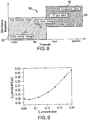
- disturbances may be categorized, e.g., by the time scale and/or magnitude by which they affect E 95 bandwidth, as illustrated by way of example in the disturbance effect chart of FIG. 8 .
- Setpoint changes in laser operating parameters, e.g., output pulse energy 90 can constitute, e.g., low magnitude disturbances that can, e.g., affect E 95 on a very fast timescale, typically msec to sec, i.e., in the fine actuation range 82.
- control action may, e.g., be divided into coarse actuation and fine actuation.
- a coarse actuator(s) may, e.g., singly or in combination with another actuator, e.g., target large magnitude changes that occur at low frequency.
- this may include large E 95 setpoint changes, gas aging effects and the long timescale component of duty cycle changes (resulting, e.g., from slow thermal loading variations, increase in age of laser components and the like).
- a fine actuator(s) may, e.g., alone or in combination with another actuator, target smaller magnitude but higher frequency disturbances, such as laser system output pulse energy, and the fast component of duty cycle changes (resulting, e.g., from faster thermal loading transients and the like).
- the coarse actuator(s) can also serve, e.g., to de-saturate, or re-center, a fine actuator(s) within its control range.
- the fine actuator's control output can, e.g., trend towards its minimum or maximum value, and then, e.g., the coarse actuator can apply corrective action in such a way as to restore the fine actuator back towards its centered value, e.g., nominally 50% if control authority is balanced in both the positive and negative directions.
- One viable choice for a coarse actuator can be F 2 gas injection, which can, e.g., adjust the F 2 concentration of the laser chamber, e.g., in ways discussed in above referenced co-pending patent applications.
- one of the fine actuator choices available may be, e.g., control of the relative time delay, denoted ⁇ T MOPA , between the commutation of the Master-Oscillator ("MO”) and Power-Amplifier ("PA”) or Power Oscillator (“PO”) pulsed-power supply (not shown).
- ⁇ T MOPA the relative time delay
- PA Power-Amplifier
- PO Power Oscillator
- alternatives can include manipulation of the curvature of the Linewidth Narrowing Module (LNM) grating surface.
- LNM Linewidth Narrowing Module
- regulating the fluorine (F 2 ) gas concentration in the laser chamber can, e.g., provide an effective means of coarse control of E 95 bandwidth.
- the chamber comprises a gain medium between the.fully reflective Line Narrowing Module (LNM) and the partially reflective Output Coupler (OC), i.e., forming a laser resonance oscillator cavity.
- LNM Line Narrowing Module
- OC partially reflective Output Coupler
- the LNM progressively narrows the spectrum of incident light after each round trip to the OC and back. Each round trip through the cavity increases the stimulated emission of light and therefore the light output energy. Eventually the stimulated emission depletes all of the energy stored in the gain medium of the oscillator and the laser pulse ends.
- Increasing the chamber F 2 concentration e.g., increases the gain, speeding the build-up of energy in the cavity.
- the stored energy can.then be depleted more rapidly because there is more stimulated emission, so the laser is above the oscillation threshold for less time. Due to the finite speed of light, this can equate to fewer round trips, which can decrease the line narrowing of the light, and thus the E 95 bandwidth can be larger. Decreasing the chamber F2 concentration can have the opposite effect, i.e., it can reduce the E 95 bandwidth.
- FIG. 9 illustrates by way of example how E 95 bandwidth of light exiting the laser system can vary, e.g., as F 2 concentration is adjusted in the MO chamber on a typical MOPA configuration, e.g., a Cymer XLA 1XX, 2XX or 3XX multi-chamber laser system platform (a "MOPA" system), which also is similar to a single chamber laser system response, e.g., from a Cymer ELS-7010 laser system platform.
- FIG. 9 illustrates, e.g., an E 95 bandwidth control authority using F 2 concentration.
- F 2 concentration as a coarse actuator to control E 95 bandwidth has a number of advantages, including, e.g., (1) the addition of F 2 to the laser gas, or its natural depletion as the laser is operated, can affect other chamber performance parameters slowly enough (e.g., minutes or more) that other fast controllers (energy, wavelength, timing, etc.) may, e.g., be effectively decoupled and are able to track without error, e.g., under the control of a separate higher frequency control actuator; and (2) the available range of actuation is large enough to, e.g., attenuate the sources of bandwidth deviation being targeted, e.g., long term duty cycle variations, gas aging and component aging. Slow changes tend to have a larger dynamic range so the larger signal disturbances can be corrected, however, more slowly, and vice-versa for disturbances that can be targeted more quickly for those types of disturbances that require a quicker response.
- FIG. 10 illustrates an effect of above noted F 2 injection techniques used as a coarse-actuation on E 95 bandwidth, e.g., on a single chamber Cymer ELS-7010 platform.
- the data displayed on the chart shows E 95 bandwidth measurements taken, e.g., every 30 seconds over a, e.g., 10 hour test, i.e., about 500 million shots.
- the exemplary laser was fired at 75% duty cycle and the output energy was 10mJ.
- the controller 60 was able to regulate E 95 to a 0.84 pm setpoint with and a Total Included Range (TIR) of less than 50 fm for more than 450Mshots.
- TIR Total Included Range
- FIG. 12 illustrates by way of example the effect of above noted F 2 injection techniques used as a coarse-actuation on E 95 bandwidth, e.g., on a dual-chamber Cymer XLA 200 platform, e.g., as discussed in Toshihiko Ishihara, Rafac, et al., "XLA-200: the third-generation ArF MOPA light source for immersion lithography", Optical Microlithography XVIII, Bruce W. Smith, Editor, Proceedings of SPIE, Volume 5754 (2005) pp. 773-779 .
- the data displayed on the chart shows E 95 bandwidth measurements taken every, e.g., 30 seconds over, e.g., a 10 hour test, i.e., about 110 million shots.
- the exemplary laser was fired at 75% duty cycle and the output energy was 10mJ.
- the controller 60 was able to regulate E 95 to about a 0.275 pm setpoint with and a Total Included Range (TIR) of less than 15 fm. Both of these experiments illustrate the extremely tight control achievable with F 2 injections.
- E95 bandwidth may be seen to be sensitive to the relative time delay, denoted ⁇ TMOPA, between the commutation of the MO and PA pulse power.
- the MO pulse becomes more line-narrowed over its duration as explained above. The effect of this can be seen to be that as the PA chamber is fired later relative to the MO chamber, it selects a more line-narrowed portion of the MO pulse and the effective E95 bandwidth of the laser decreases.
- FIG. 11 shows how E95 bandwidth can vary as differential firing time is adjusted, e.g., on a typical MOPA configuration dual chamber laser system.
- FIG. 11 illustrates, e.g., an E 95 bandwidth control authority using ⁇ t MOPA .
- differential firing time as a fine actuator to control E 95 bandwidth has a number of advantages, e.g., (1) the measurement of E 95 and the change of ⁇ t MOPA both can occur, e.g., on about a tens-of-pulses time scale, or shorter, e.g., pulse-to-pulse, e.g., allowing for very high frequency disturbance rejection. That is, disturbances can be suppressed very quickly; and (2) the available range of actuation can be seen to be large enough to, e.g., attenuate/suppress the sources of bandwidth deviation being targeted, namely laser energy and the higher frequency effects of duty cycle variations.
- FIG. 12 illustrates the effect of the ⁇ t MOPA fine-actuator and F2 inject coarse-actuator, e:g., in a dual stage controller 60.
- the displayed data on the chart shows, e.g., maximum and minimum E 95 bandwidth measurements taken every 30 seconds during a seven hour test, e.g., E 95 min curve 100 without dual stage control and a max E 95 curve 102 without dual stage control, and a min e 95 curve with dual stage control 104 and a similar max E 95 curve 106.
- the laser was fired at 75% duty cycle and the output energy of nominally 10mJ, i.e., switched between 9 mJ and 11 mJ every half hour Indicated by the spikes in curves 104 and 106 and the step changes in curves 100 and 102.
- the lower set of curves 102, 104 illustrate the kind of behavior when, e.g., only one actuator, e.g., one coarse actuator, e.g., F 2 inject control), is applied and the upper curves 104, 106, illustrate the effect when, e.g., a fine actuator, e.g., differential commutation control, is also used, e.g., to stabilize E 95 bandwidth, along with the F 2 injection control and to also shift it up to a setpoint value of 0.35 pm.
- a fine actuator e.g., differential commutation control
- the data illustrates a dramatic improvement, whereby, e.g., timing control has stabilized E 95 bandwidth to well within the limits of the E 95 metrology.
- Modifying the optical wavefront and/or modifying the interaction between the wavefront and, e.g., the line narrowing module grating, within the laser's line narrowing module, e.g., by changing the shape of the grating surface (or otherwise modifying the wavefront shape incident on the grating face elsewhere in the optical train, can also be an affective optical method of regulating E 95 bandwidth, e.g., with fine resolution on a relatively fast time scale, e.g., on the order of seconds.
- FIG. 1 illustrates the relationship between E 95 and a normalized grating curvature, which can be seen to be roughly quadratic in nature.
- FIG. 4 illustrates, e.g., E 95 setpoint regulation on a Cymer ELS-7010 platform, demonstrating a transition between two E 95 bandwidth setpoints. e.g., around 0.875 pm and about 0.710 pm, e.g., using grating wavefront curvature change.
- F 2 injection control may be done, e.g., according to one or more algorithms, such as JAFFA or AFI described in one or more of the above referenced co-pending patent applications and BCD control may be done, e.g., with active BCD deformation based on BW error feedback, e.g., with a pneumatic BCD bending mechanism, the details of which are discussed in one or more of the above referenced co-pending patent applications and dt MOPA may be selected and modified, e.g., using a timing and energy control module, such as is sold on applicant's assignee's existing XLA XX model laser systems, e.g., to control dtMOPA based on bandwidth error feedback, and also described in one or more of the patents or co-pending applications noted above.
- a timing and energy control module such as is sold on applicant's assignee's existing XLA XXX model laser systems, e.g., to control dtMOPA based on bandwidth error feedback, and
- a bandwidth control system e.g., an F 2 injection control system may be desensitized to the impact of other laser operating parameters on the measured error signal for a feedback control parameter, e.g., by desensitizing measurements of the parameter, e.g., bandwidth measured in E 93 , bandwidth measured in FWHM, dtMOPA, energy output of the MO ("E mo "), Voltage, MO operating point and the like to changes in other parameters, e.g., energy target (“E”) and duty cycle (“DC”).
- FIG. 13 illustrates schematically and in block diagram form such a system.
- E 13 shows, e.g., bandwidth, e.g., measured as E 95 , voltage, MOPA timing ("dtMOPA") and energy out of the MO (“E MO ”) (e.g., E 95 ) being so called “normalized” and applied to determine, e.g., an amount of F 2 that has been consumed in the laser system chamber (or in one of two or more respective laser system chambers) based also on "trust" coefficients that reflect, e.g., the confidence in the measured quantity (e.g., due to signal to noise ratio in the measurement(s)) and/or the stability/predictability of the respective empirically determined relationship of, e.g., the change in F 2 concentration (i.e., the amount of F 2 consumed) for a given change in the respective laser system operating parameter.
- the respective laser system operating parameter e.g., E 95 , V, dtMOPa and E MO measured error signal (variance from a selected setpoint) may, as illustrated in FIG. 13 by way of example be filtered in some fashion, e.g., a low pass filter [e.g., by averaging over a selected number of measurements, measurements for E 95 in a respective filter, 112, 112', 112" and 112"'.
- the respective filtered error signals may then be adjusted for the current Energy target, e.g., the energy measured at the laser system overall output, e.g., at the shutter.
- the filtered parameter, e.g., E 95 may then be modified according to energy Target E tgt , e.g., by having subtracted from it a value based upon the current energy target, e.g., 10mJ, e.g., based on a relationship empirically determined, e.g., ⁇ F ⁇ 2 / ⁇ E tgt , between the change in estimated fluorine consumption ⁇ F ⁇ 2 and the change in energy target ⁇ E tgt in the respective E tgt correction boxes 114, 114', 114" and 114"' for the respective parameters E 95 , V, dtMOPa and E MO or other like values, e.g., dV/dE, DE95/dE, dFWHM/dE, etc.
- the laser operating parameter e.g., E 95 error may be normalized for, e.g., duty cycle, e.g., having the value ⁇ F ⁇ 2 / ⁇ DC subtracted from it to scale the change in duty cycle by the sensitivity of, e.g., E 95 to duty cycle, or other like values, e.g., dV/dE, DE95/dE, dFWHM/dE, etc..
- Estimates for the sensitivities of, e.g., E 95 , V, dtMOPA or E MO to, e.g., influencing variable laser performance parameters, e.g., duty cycle and shutter energy may be estimated by, e.g., running a calibration test which varies energy or duty cycle and measures the changes in, e.g., E 95 V, dtMOPA or E MO .
- the respective estimated fluorine consumption ⁇ F ⁇ 2 may be calculated for the given normalized error signal, e.g., according to the equation (E 95REF - E 95N ) x (dF 2 /dE 95 ), where (E 95REF - E 95N ) is the output of the combination of, e.g., the two respective parameter correction boxes 114, 116 and (dF 2 /dE 95 ) is an empirically determined sensitivity of F ⁇ 2 , the estimated fluorine consumption for a given laser system operating parameter change, such as dE 95 .
- the respective estimated injection amounts to compensate for the collective changes in the operating parameters e.g., as illustrated by way of example in FIG. 13 , E 95 .
- V, dtMOPA and EMO may be multiplied by a respective trust coefficient, e.g., C 1 , C 2 , ...
- the F2 injection control algorithm may compare the current value of F ⁇ 2TOT to an inject min and, e.g., hold off on injecting if the current estimate of the total fluorine consumption since the last inject, F ⁇ 2TOT , is less than inject min .
- a recursive least squares (RLS) filter may be used after the LPF 112, e.g., to automatically identify box 114 and 116, e.g., to estimate the duty cycle and shutter energy sensitivities in real time.
- d[n] is the current value of the error measurement, e.g., as shown in FIG. 14 the MO energy error
- w[n] is the estimate of the sensitivities of the measurement with respect to the input data in the vector
- u[n] and P[n] together form an estimate of the inverse covariance of the parameter estimates in the input data vector.
- the value, ⁇ is a forgetting factor, such that, e.g., setting ⁇ to unity gives equal weight to all data, while setting it to a lesser value applies lesser weight to older data.
- n is a sample index.
- the vector of input data can, e.g., include the data to which one wishes to desensitize the respective error measurement (e.g., duty cycle data) and (possibly) other data (e.g., energy data) to improve the performance of the algorithm 130.
- the values of K, e, w[n] and P[n] may be utilized to modify the error signal, e.g., EMO by use of such values to, e.g., modify the signal based on, e.g., DC or energy targets.
- the data vector includes the duty cycle change 116"', shutter energy change 114"' and an offset, e.g., as follows: u n ⁇ ⁇ DC change n E change n 1 ⁇
- FIG. 15 shows the application of this algorithm, e.g., to voltage during a test where, e.g., energy target was varied every half hour, e.g., after a gas refill.
- the curve 140 is the raw voltage measurement data and the curve 142 is the adjusted voltage measurement.
- the algorithm 130 employing the RLS filter 136 correctly identifies and compensates out the effect of the change in an influencing laser operation parameter, e.g., changes in energy target as it influences the change in measured voltage.
- the algorithm may be utilized to, e.g., remove the effects of laser operating parameters unrelated to gas consumption estimates, e.g., other than gas consumption and inject effects from the respective adjusted error signal related to, e.g., E 95 , V, dtMOPA or E MO .
- an end of gas life end which may conveniently be defined, e.g., for the purposes of this application as the point in the laser operation where there is, e.g., no longer enough control authority on voltage with, e.g., fluorine content to ensure an output parameter that is desired to be kept stable, e.g., output energy setpoint, can be maintained, e.g., where another parameter may go out of spec, e.g., the voltage rising to the upper rail, upon which also, e.g., the output energy may drop below the setpoint and the laser may then shut down.
- the laser may be enabled to operate for a variable gas life length, which under certain conditions may be much larger than the current specified gas life time, which, by way of example may simply be a more or less empirically determined value set, e.g., at fixed time since laser refill or a fixed shot count or the like.
- an event time to perform a refill may, e.g., be predicted using logic applied to an analysis of certain gas control algorithm internal state variables, such as dE95/dF 2 d( ⁇ tMOPA)/dF 2 , ddV/dE, dE95/dE, dFWHM/dE, etc. dV/dF 2 , etc.
- Such an apparatus and method may employ, e.g., looking at the estimator sensitivities of, e.g., an F2 injection algorithm, e.g. dE95/dF 2 , d( ⁇ t MOPA )/dF 2 , dV/dF 2 , dFWHM/dF 2 , dEmo/dF 2 , etc., and, evaluating, e.g., the rate at which they are trending toward a particular value, e.g., an extremum, e.g., a minimum value or their proximity to the minimum value.
- FIG. 16-18 illustrate by way of example, e.g., real data taken on an XLA system, such as applicants' assignee's XLA XXX lasers.
- the plot of FIG. 16 e.g., relates to the sensitivity of a laser operating parameter, e.g., the change in the differential firing time, dtMOPA, with respect to change in fluorine concentration, otherwise expressed as d( ⁇ t MOPA )/dF 2 .
- the value over time can, e.g., converge to a particular more or less steady state value, e.g., to ⁇ -200 for a determinable period of time, e.g., for about the first 10x10 7 shots (100 M shots) and then tend toward another value, e.g., trend steadily towards, e.g., a least sensitive bound, i.e., -50 by a determinable amount of time, e.g., by about 180M shots.
- Such a convergence, e.g., to zero may, e.g., be correlated with the end of gas life as defined above.
- a line narrowed high average power high pulse repetition laser micro-photolithography light source bandwidth control method and apparatus may comprise a bandwidth metrology module measuring the bandwidth of a laser output light pulse beam pulse produced by the light source and providing a bandwidth measurement; a bandwidth error signal generator receiving the bandwidth measurement and a bandwidth setpoint and providing a bandwidth error signal; an active bandwidth controller providing a fine bandwidth correction actuator signal and a coarse bandwidth correction actuator signal responsive to the bandwidth error.
- the fine bandwidth correction actuator and the coarse bandwidth correction actuator each may induce a respective modification of the light source behavior that reduces bandwidth error.
- the coarse and fine bandwidth correction actuators each may comprise a plurality of bandwidth correction actuators.
- the coarse bandwidth correction actuator may target large amplitude disturbances occurring at low frequency, e.g., on the order of minutes to months and the fine bandwidth correction actuator may target small amplitude disturbances occurring at high frequency, e.g., on the order of msecs to minutes.
- the large amplitude disturbances comprising one or more of the group of large E95 setpoint changes, which can vary from product to product, gas aging effects and the long timescale (e.g., minutes or more) component of duty cycle setpoint changes, e.g., over 1 minute, and the smaller amplitude disturbances comprising one or more of the group comprising laser system output pulse energy setpoint changes, e.g., of more than 1% of the mJ setting, and the fast component (minutes of less) of duty cycle setpoint changes, e.g., ⁇ 1 minute.
- the apparatus and method may comprise fine actuator control output trends toward a minimum or maximum value; coarse actuator control applying corrective action in such a way as to move the fine actuator back towards a centered value.
- a line narrowed high average power high pulse repetition laser micro-photolithography light source bandwidth control method and apparatus may comprise a laser operating parameter metrology module measuring the laser operating parameter of a laser output light pulse beam pulse produced by the light source and providing a laser operating parameter measurement; a laser operating parameter error signal generator receiving the laser operating parameter measurement and a laser operating parameter setpoint and providing a laser operating parameter error signal; a laser operating parameter error signal modifier modifying the laser operating parameter error signal according to the sensitivity of the laser operating parameter to another laser operating parameter comprising a real time estimation filter.
- the laser operating parameter error signal modifier may modify the laser operating parameter error signal according to the sensitivity of the laser operating system parameter to each of a plurality of other laser operating parameters.
- the laser operating parameter may be selected from the group comprising bandwidth (E xx , that is, the integral of some portion XX % of the total energy in the spectrum.), bandwidth (FWXM, that is, the full width at some portion X % of the maximum, e.g., FWH(alf)M, FW(25%)M, FW(75%)M, etc.), energy out of the seed laser (EMO), differential firing time between the seed laser and amplifier gain medium (dtMOPA), and voltage (V).
- the other laser operating parameter may be selected from the group comprising duty cycle (DC) and laser system output energy, e.g., at the output shutter (E sht ) and voltage (V).
- a line narrowed high average power high pulse repetition laser micro-photolithography light source fluorine injection control method and apparatus may comprise a laser operating parameter measurement mechanism measuring a laser operating parameter of the light source; a laser operating parameter tracking mechanism providing a representation of the value of the laser operating parameter over time; a laser system gas refill prediction mechanism predicting the time for a gas fill based upon the trending of the value of the laser operating parameter between a first relatively constant steady state trend value and a limiting value.
- the laser operating parameter may be selected from the group comprising voltage (V), differential firing time (dtMOPA), bandwidth at the energy percentage integral, i.e., E 95% , E xx% , etc., energy out of the master oscillator, EMO, energy out of the amplification gain medium, e.g., PA or PO or other type of amplification gain stage (e.g., dual chamber laser output energy), E PA, E PO or E out of any other amplification gain stage, e.g., a ring power amplification stage, of energy out of the laser system, e.g., at the shutter, E sht , etc.
- V voltage
- dtMOPA differential firing time
- Applicant(s) has used from time to time or throughout the present application definitive verbs (e.g., “is”, “are”, “does”, “has”, “includes” or the like) and/or other definitive verbs (e.g., “produces,” “causes” “samples,” “reads,” “signals” or the like) and/or grands (e.g., “producing,” “using,” “taking,” “keeping,” “making,” “determining,” “measuring,” “calculating” or the like), in defining an aspect/feature/element of, an action of or functionality of, and/or describing any other definition of an aspect/feature/element of an embodiment of the subject matter being disclosed.
- definitive verbs e.g., "is”, “are”, “does”, “has”, “includes” or the like
- other definitive verbs e.g., “produces,” “causes” “samples,” “reads,” “signals” or the like
- grands
- any such definitive word or phrase or the like is used to describe an aspect/feature/element of any of the one or more embodiments disclosed herein, i.e., any feature, element, system, sub-system, component, sub-component, process or algorithm step, particular material, or the like, it should be read, for purposes of interpreting the scope of the subject matter of what applicant(s) has invented, and claimed, to be preceded by one or more, or all, of the following limiting phrases, "by way of example,” “for example,” “as an example,” “illustratively only,” “by way of illustration only,” etc., and/or to include any one or more, or all, of the phrases “may be,” “can be”, “might be,” “could be” and the like.
- Applicant(s) specifically, expressly and unequivocally intends that any claim that has depending from it a dependent claim with any further detail of any aspect/feature/element, step, or the like of the subject matter of what is claimed recited in the parent claim or claims from which it directly or indirectly depends, shall be interpreted to mean that the recitation in the parent claim(s) was broad enough to cover the further detail in the dependent claim along with other implementations and that the further detail was not the only way to implement the aspect/feature/element claimed in any such parent claim(s), and thus be limited to the further detail of any such aspect/feature/element recited in any such dependent claim to in any way limit the scope of the broader aspect/feature/element of any such parent claim, including by incorporating the further detail of the dependent claim into the parent claim.
Landscapes
- Physics & Mathematics (AREA)
- Electromagnetism (AREA)
- Engineering & Computer Science (AREA)
- Plasma & Fusion (AREA)
- Optics & Photonics (AREA)
- General Physics & Mathematics (AREA)
- Lasers (AREA)
- Spectroscopy & Molecular Physics (AREA)
Claims (6)
- Steuersystem (40) für linienverengte Laser-Mikrofotolithographie-Lichtquellenbandbreiten mit hoher mittlerer Leistung und hoher Pulswiederholung, umfassend:ein Bandbreiten-Messmodul (44), das ausgebildet ist, die Bandbreite eines Impulses eines Laserausgangslichtpulsstrahls (52), der von der Lichtquelle (42) erzeugt wird, zu messen und eine Bandbreitenmessung (54) bereitzustellen;ein Bandbreiten-Fehlersignalerzeugungsvorrichtung (64), die konfiguriert ist, die Bandbreitenmessung (54) und einen Bandbreiten-Sollwert (62) zu empfangen und ein Bandbreitenfehlersignal bereitzustellen;einen Aktuator zur feinen Bandbreitenkorrektur (74);eine aktive Bandbreitensteuerung (60), die konfiguriert ist, ein Fehlersignal der feinen Bandbreitenkorrektur und ein grobes Bandbreitenkorrektur-Aktuatorsignal auf der Grundlage des Bandbreitenfehlersignals, das durch die Bandbreiten-Fehlersignalerzeugungsvorrichtung gebildet wird, zu berechnen, und das feine Bandbreitenkorrektur-Aktuatorsignal an den Aktuator zur feinen Bandbreitekorrektur (74) zu leiten;wobei der Aktuator zur feinen Bandbreitenkorrektur (74) umfasst:eine Relativzeitverzögerungssteuerung zur Steuerung einer relativen Zeitverzögerung zwischen dem Austausch einer Hauptoszillator-Pulsstromversorgung und einem Leistungsverstärker oder einer Leistungsoszillator-Pulsstromversorgung der Laser-Mikrofotolithographie-Lichtquelle oder eine Gitterkrümmungssteuerung zur Steuerung einer Krümmung eines Gitters in einem Linienverkleinerungsmodul der Laser-Mikrofotolithographie-Lichtquelle,dadurch gekennzeichnet, dassdas System (40) ferner einen Aktuator zur groben Bandbreitenkorrektur (72) umfasst, der eine Fluoreinspritzsteuerung, die zur Einstellung einer Fluorkonzentration in einer Laserkammer der Laser-Mikrofotolithographie-Lichtquelle geeignet ist, umfasst;wobei der Aktuator zur groben Bandbreitenkorrektur konfiguriert ist, eine erste Laserkomponente zu schalten, um eine Bandbreite des Laserausgangslichtpulsstrahl auf einen ersten Zeitrahmen einzustellen, und der Aktuator zur feinen Bandbreitenkorrektur konfiguriert ist, eine zweite Laserkomponente zu schalten, die sich von der ersten Laserkomponente unterscheidet, um die Bandbreite des Laserausgangslichtpulsstrahl auf einen zweiten Zeitrahmen einzustellen, der schneller als der erste Zeitrahmen ist;und wobei die aktive Bandbreitensteuereinheit konfiguriert ist, eine Aktuatorsignal zur groben Bandbreitenkorrektur auf der Grundlage des Bandbreitenfehlersignals zu berechnen, das durch die Bandbreiten-Fehlersignalerzeugungsvorrichtung gebildet wird, und das Aktuatorsignal zur groben Bandbreitenkorrektur an den Aktuator zur groben Bandbreitenkorrektur (72) weiterzuleiten.
- Vorrichtung nach Anspruch 1, wobei der Aktuator zur groben (72) und zur feinen (74) Bandbreitenkorrektur jeweils eine Vielzahl von Bandbreitenkorrekturaktuatoren umfasst.
- Vorrichtung nach einem der Ansprüche 1 und 2, wobei der Aktuator zur groben Bandbreitenkorrektur (72) große Amplitudenstörungen, die bei einer niedrigen Frequenz auftreten, anspricht und der Aktuator zur feinen Bandbreitenkorrektur (74) kleine Amplitudenstörungen, die bei hoher Frequenz auftreten, anspricht.
- Vorrichtung nach Anspruch 3, wobei die großen Amplitudenstörungen eine oder mehrere der Gruppen ausgewählt aus großen E95 Sollwertänderungen, Gasalterungseffekten und den Langzeitrahmenkomponenten von Tastverhältnis-Sollwert-Änderungen umfassen, und die kleinen Amplitudenstörungen eine oder mehrere der Gruppe umfassend einen Lasersystem-Ausgangsimpuls-Energiesollwert und die schnelle Komponente der Tastverhältnis-Sollwert-Änderung umfassen.
- Vorrichtung nach einem der Ansprüche 1 bis 4, wobei die Steuerungsausgabe des Aktuators zur Grobeinstellung in Richtung eines Höchst- oder Tiefstwerts tendiert; und die Steuerung des Aktuators zur Grobeinstellung Korrekturmaßnahmen in einer Weise anwendet, um den Aktuator zur Feineinstellung zurück in Richtung eines mittleren Wertes zu bewegen.
- Vorrichtung nach Anspruch 5, wobei der mittlere Wert nominell 50% umfasst, bei dem die Steuerung in sowohl den positiven und negativen Richtungen ausgeglichen ist.
Priority Applications (1)
| Application Number | Priority Date | Filing Date | Title |
|---|---|---|---|
| EP11178106.8A EP2388800B1 (de) | 2006-02-17 | 2007-01-22 | Aktive Spektralsteuerung einer tief ultravioletten Lichtquelle |
Applications Claiming Priority (3)
| Application Number | Priority Date | Filing Date | Title |
|---|---|---|---|
| US77477006P | 2006-02-17 | 2006-02-17 | |
| US11/510,037 US7852889B2 (en) | 2006-02-17 | 2006-08-25 | Active spectral control of DUV light source |
| PCT/US2007/001667 WO2007097855A2 (en) | 2006-02-17 | 2007-01-22 | Active spectral control of duv light source |
Related Child Applications (2)
| Application Number | Title | Priority Date | Filing Date |
|---|---|---|---|
| EP11178106.8A Division-Into EP2388800B1 (de) | 2006-02-17 | 2007-01-22 | Aktive Spektralsteuerung einer tief ultravioletten Lichtquelle |
| EP11178106.8A Division EP2388800B1 (de) | 2006-02-17 | 2007-01-22 | Aktive Spektralsteuerung einer tief ultravioletten Lichtquelle |
Publications (3)
| Publication Number | Publication Date |
|---|---|
| EP1994549A2 EP1994549A2 (de) | 2008-11-26 |
| EP1994549A4 EP1994549A4 (de) | 2009-08-05 |
| EP1994549B1 true EP1994549B1 (de) | 2016-12-07 |
Family
ID=38428147
Family Applications (2)
| Application Number | Title | Priority Date | Filing Date |
|---|---|---|---|
| EP11178106.8A Active EP2388800B1 (de) | 2006-02-17 | 2007-01-22 | Aktive Spektralsteuerung einer tief ultravioletten Lichtquelle |
| EP07716893.8A Active EP1994549B1 (de) | 2006-02-17 | 2007-01-22 | Aktive spektralsteuerung einer duv-lichtquelle |
Family Applications Before (1)
| Application Number | Title | Priority Date | Filing Date |
|---|---|---|---|
| EP11178106.8A Active EP2388800B1 (de) | 2006-02-17 | 2007-01-22 | Aktive Spektralsteuerung einer tief ultravioletten Lichtquelle |
Country Status (6)
| Country | Link |
|---|---|
| US (2) | US7852889B2 (de) |
| EP (2) | EP2388800B1 (de) |
| JP (2) | JP5420909B2 (de) |
| KR (1) | KR101390217B1 (de) |
| TW (2) | TWI470888B (de) |
| WO (1) | WO2007097855A2 (de) |
Families Citing this family (23)
| Publication number | Priority date | Publication date | Assignee | Title |
|---|---|---|---|---|
| US7830934B2 (en) * | 2001-08-29 | 2010-11-09 | Cymer, Inc. | Multi-chamber gas discharge laser bandwidth control through discharge timing |
| US7659529B2 (en) * | 2007-04-13 | 2010-02-09 | Cymer, Inc. | Method and apparatus for vibration reduction in laser system line narrowing unit wavelength selection optical element |
| US9018561B2 (en) * | 2007-05-23 | 2015-04-28 | Cymer, Llc | High power seed/amplifier laser system with beam shaping intermediate the seed and amplifier |
| US7830942B2 (en) * | 2007-09-11 | 2010-11-09 | Cymer, Inc. | Ultraviolet laser light source pulse energy control system |
| US7756171B2 (en) * | 2008-10-21 | 2010-07-13 | Cymer, Inc. | Method and apparatus for laser control in a two chamber gas discharge laser |
| US7751453B2 (en) * | 2008-10-21 | 2010-07-06 | Cymer, Inc. | Method and apparatus for laser control in a two chamber gas discharge laser |
| US7720120B2 (en) * | 2008-10-21 | 2010-05-18 | Cymer, Inc. | Method and apparatus for laser control in a two chamber gas discharge laser |
| US8520186B2 (en) * | 2009-08-25 | 2013-08-27 | Cymer, Llc | Active spectral control of optical source |
| US8254420B2 (en) * | 2009-11-18 | 2012-08-28 | Cymer, Inc. | Advanced laser wavelength control |
| NL2006073A (en) * | 2010-02-12 | 2011-08-15 | Asml Netherlands Bv | Lithographic apparatus and method. |
| US8837536B2 (en) * | 2010-04-07 | 2014-09-16 | Cymer, Llc | Method and apparatus for controlling light bandwidth |
| US8432944B2 (en) * | 2010-06-25 | 2013-04-30 | KLA-Technor Corporation | Extending the lifetime of a deep UV laser in a wafer inspection tool |
| US9715180B2 (en) | 2013-06-11 | 2017-07-25 | Cymer, Llc | Wafer-based light source parameter control |
| US10395134B2 (en) | 2013-07-26 | 2019-08-27 | University Of Utah Research Foundation | Extraction of spectral information |
| US9065248B2 (en) * | 2013-11-20 | 2015-06-23 | Cymer, Llc | Systems and methods to more accurately estimate a fluorine concentration in a source laser |
| US9261794B1 (en) * | 2014-12-09 | 2016-02-16 | Cymer, Llc | Compensation for a disturbance in an optical source |
| US9785050B2 (en) | 2015-06-26 | 2017-10-10 | Cymer, Llc | Pulsed light beam spectral feature control |
| US9989866B2 (en) * | 2016-10-17 | 2018-06-05 | Cymer, Llc | Wafer-based light source parameter control |
| US9966725B1 (en) | 2017-03-24 | 2018-05-08 | Cymer, Llc | Pulsed light beam spectral feature control |
| US11081852B2 (en) * | 2017-04-24 | 2021-08-03 | Cymer, Llc | Laser light energy and dose control using repetition rate based gain estimators |
| US10833471B2 (en) | 2017-11-17 | 2020-11-10 | Cymer, Llc | Lithography system bandwidth control |
| JP7515001B2 (ja) | 2020-08-18 | 2024-07-11 | サイマー リミテッド ライアビリティ カンパニー | 予測的に較正をスケジュール設定する装置及び方法 |
| CN115332924B (zh) * | 2022-09-01 | 2024-11-01 | 中国人民解放军国防科技大学 | 一种用于产生灵巧波形高功率微波的光纤激光器 |
Citations (1)
| Publication number | Priority date | Publication date | Assignee | Title |
|---|---|---|---|---|
| US20020154668A1 (en) * | 1999-12-10 | 2002-10-24 | Knowles David S. | Very narrow band, two chamber, high rep rate gas discharge laser system |
Family Cites Families (33)
| Publication number | Priority date | Publication date | Assignee | Title |
|---|---|---|---|---|
| US4823354A (en) | 1987-12-15 | 1989-04-18 | Lumonics Inc. | Excimer lasers |
| US4881231A (en) | 1988-11-28 | 1989-11-14 | Kantilal Jain | Frequency-stabilized line-narrowed excimer laser source system for high resolution lithography |
| US5982800A (en) | 1997-04-23 | 1999-11-09 | Cymer, Inc. | Narrow band excimer laser |
| US6721340B1 (en) * | 1997-07-22 | 2004-04-13 | Cymer, Inc. | Bandwidth control technique for a laser |
| US6671294B2 (en) | 1997-07-22 | 2003-12-30 | Cymer, Inc. | Laser spectral engineering for lithographic process |
| US6151349A (en) | 1998-03-04 | 2000-11-21 | Cymer, Inc. | Automatic fluorine control system |
| US6493374B1 (en) * | 1999-09-03 | 2002-12-10 | Cymer, Inc. | Smart laser with fast deformable grating |
| JP2000150998A (ja) * | 1998-11-06 | 2000-05-30 | Komatsu Ltd | エキシマレーザ装置の狭帯域化モジュール |
| US6389052B2 (en) | 1999-03-17 | 2002-05-14 | Lambda Physik Ag | Laser gas replenishment method |
| US6882674B2 (en) | 1999-12-27 | 2005-04-19 | Cymer, Inc. | Four KHz gas discharge laser system |
| US6801560B2 (en) | 1999-05-10 | 2004-10-05 | Cymer, Inc. | Line selected F2 two chamber laser system |
| JP2003511865A (ja) | 1999-10-14 | 2003-03-25 | ランブダ フィジク アクチェンゲゼルシャフト | エキシマ又は分子フッ素レーザのエネルギー制御 |
| US6650666B2 (en) * | 2000-02-09 | 2003-11-18 | Cymer, Inc. | Laser wavelength control unit with piezoelectric driver |
| US6788719B2 (en) * | 2000-05-04 | 2004-09-07 | Agility Communications, Inc. | Open loop control of SGDBR lasers |
| US6914919B2 (en) * | 2000-06-19 | 2005-07-05 | Cymer, Inc. | Six to ten KHz, or greater gas discharge laser system |
| US6856638B2 (en) * | 2000-10-23 | 2005-02-15 | Lambda Physik Ag | Resonator arrangement for bandwidth control |
| DE10054244C2 (de) * | 2000-11-02 | 2002-10-10 | Honda Motor Co Ltd | Turbinenblattanordnung und Turbinenblatt für eine Axialturbine |
| GB0027238D0 (en) * | 2000-11-08 | 2000-12-27 | Secr Defence | Adaptive filter |
| US7039086B2 (en) * | 2001-04-09 | 2006-05-02 | Cymer, Inc. | Control system for a two chamber gas discharge laser |
| US7830934B2 (en) | 2001-08-29 | 2010-11-09 | Cymer, Inc. | Multi-chamber gas discharge laser bandwidth control through discharge timing |
| US6963595B2 (en) * | 2001-08-29 | 2005-11-08 | Cymer, Inc. | Automatic gas control system for a gas discharge laser |
| JP2003172180A (ja) * | 2001-11-30 | 2003-06-20 | Hitachi Unisia Automotive Ltd | 内燃機関の空燃比制御装置 |
| JP3888673B2 (ja) | 2001-12-28 | 2007-03-07 | ウシオ電機株式会社 | 露光用フッ素分子レーザシステム |
| JP4094307B2 (ja) * | 2002-02-21 | 2008-06-04 | ギガフォトン株式会社 | ガスレーザ装置 |
| US7741639B2 (en) | 2003-01-31 | 2010-06-22 | Cymer, Inc. | Multi-chambered excimer or molecular fluorine gas discharge laser fluorine injection control |
| US7277464B2 (en) | 2003-12-18 | 2007-10-02 | Cymer, Inc. | Method and apparatus for controlling the output of a gas discharge laser system |
| US7352858B2 (en) * | 2004-06-30 | 2008-04-01 | Microsoft Corporation | Multi-channel echo cancellation with round robin regularization |
| JP4798687B2 (ja) * | 2004-07-09 | 2011-10-19 | 株式会社小松製作所 | 狭帯域化レーザ装置 |
| US7643522B2 (en) | 2004-11-30 | 2010-01-05 | Cymer, Inc. | Method and apparatus for gas discharge laser bandwidth and center wavelength control |
| US20060114956A1 (en) | 2004-11-30 | 2006-06-01 | Sandstrom Richard L | High power high pulse repetition rate gas discharge laser system bandwidth management |
| US7317536B2 (en) | 2005-06-27 | 2008-01-08 | Cymer, Inc. | Spectral bandwidth metrology for high repetition rate gas discharge lasers |
| US7653095B2 (en) | 2005-06-30 | 2010-01-26 | Cymer, Inc. | Active bandwidth control for a laser |
| JP2007142052A (ja) * | 2005-11-16 | 2007-06-07 | Nikon Corp | 露光装置、レーザ光源、露光方法、及びデバイス製造方法 |
-
2006
- 2006-08-25 US US11/510,037 patent/US7852889B2/en active Active
- 2006-12-27 TW TW99116707A patent/TWI470888B/zh active
- 2006-12-27 TW TW095149174A patent/TWI347716B/zh active
-
2007
- 2007-01-22 WO PCT/US2007/001667 patent/WO2007097855A2/en not_active Ceased
- 2007-01-22 JP JP2008555241A patent/JP5420909B2/ja active Active
- 2007-01-22 EP EP11178106.8A patent/EP2388800B1/de active Active
- 2007-01-22 EP EP07716893.8A patent/EP1994549B1/de active Active
- 2007-01-22 KR KR1020087021234A patent/KR101390217B1/ko active Active
-
2010
- 2010-11-01 US US12/925,860 patent/US8098698B2/en active Active
-
2013
- 2013-01-24 JP JP2013011451A patent/JP5647700B2/ja active Active
Patent Citations (1)
| Publication number | Priority date | Publication date | Assignee | Title |
|---|---|---|---|---|
| US20020154668A1 (en) * | 1999-12-10 | 2002-10-24 | Knowles David S. | Very narrow band, two chamber, high rep rate gas discharge laser system |
Also Published As
| Publication number | Publication date |
|---|---|
| KR20080106215A (ko) | 2008-12-04 |
| TW200735493A (en) | 2007-09-16 |
| JP5420909B2 (ja) | 2014-02-19 |
| JP2009527124A (ja) | 2009-07-23 |
| EP2388800B1 (de) | 2017-12-20 |
| WO2007097855A2 (en) | 2007-08-30 |
| US20070195836A1 (en) | 2007-08-23 |
| TW201036294A (en) | 2010-10-01 |
| EP1994549A2 (de) | 2008-11-26 |
| US7852889B2 (en) | 2010-12-14 |
| EP2388800A1 (de) | 2011-11-23 |
| TWI470888B (zh) | 2015-01-21 |
| JP2013102206A (ja) | 2013-05-23 |
| TWI347716B (en) | 2011-08-21 |
| US8098698B2 (en) | 2012-01-17 |
| KR101390217B1 (ko) | 2014-05-27 |
| EP1994549A4 (de) | 2009-08-05 |
| US20110051760A1 (en) | 2011-03-03 |
| JP5647700B2 (ja) | 2015-01-07 |
| WO2007097855A3 (en) | 2008-07-24 |
Similar Documents
| Publication | Publication Date | Title |
|---|---|---|
| EP1994549B1 (de) | Aktive spektralsteuerung einer duv-lichtquelle | |
| US7643522B2 (en) | Method and apparatus for gas discharge laser bandwidth and center wavelength control | |
| US7894494B2 (en) | Method and apparatus to control output spectrum bandwidth of MOPO or MOPA laser | |
| US7057705B2 (en) | Lithographic apparatus, device manufacturing method, performance measuring method, calibration method and computer program | |
| CN107925214B (zh) | 用于光源的波长稳定化 | |
| US7822084B2 (en) | Method and apparatus for stabilizing and tuning the bandwidth of laser light | |
| US6735225B2 (en) | Chirp compensation method and apparatus | |
| US7116695B2 (en) | Laser output light pulse beam parameter transient correction system | |
| EP1361479B1 (de) | Steuerung eines lithographischen Apparates | |
| Dunstan et al. | Active Spectral Control of DUV light sources for OPE minimization | |
| CN120642155A (zh) | 激光装置、曝光装置和电子器件的制造方法 | |
| Farrar et al. | Active spectral-control techniques for improving OPC. |
Legal Events
| Date | Code | Title | Description |
|---|---|---|---|
| PUAI | Public reference made under article 153(3) epc to a published international application that has entered the european phase |
Free format text: ORIGINAL CODE: 0009012 |
|
| 17P | Request for examination filed |
Effective date: 20080916 |
|
| AK | Designated contracting states |
Kind code of ref document: A2 Designated state(s): AT BE BG CH CY CZ DE DK EE ES FI FR GB GR HU IE IS IT LI LT LU LV MC NL PL PT RO SE SI SK TR |
|
| AX | Request for extension of the european patent |
Extension state: AL BA HR MK RS |
|
| RIN1 | Information on inventor provided before grant (corrected) |
Inventor name: DUNSTAN, WAYNE J. Inventor name: RAO, RAJASEKHAR, M. Inventor name: TRINTCHOUK, FEDOR, B. Inventor name: JACQUES, ROBERT, N. |
|
| A4 | Supplementary search report drawn up and despatched |
Effective date: 20090706 |
|
| RBV | Designated contracting states (corrected) |
Designated state(s): DE FR NL |
|
| RIC1 | Information provided on ipc code assigned before grant |
Ipc: H01L 21/00 20060101AFI20081003BHEP Ipc: G03F 7/20 20060101ALI20090630BHEP |
|
| 17Q | First examination report despatched |
Effective date: 20091119 |
|
| RIN1 | Information on inventor provided before grant (corrected) |
Inventor name: JACQUES, ROBERT, N. Inventor name: RAO, RAJASEKHAR, M. Inventor name: TRINTCHOUK, FEDOR, B. Inventor name: DUNSTAN, WAYNE J. |
|
| DAX | Request for extension of the european patent (deleted) | ||
| RAP1 | Party data changed (applicant data changed or rights of an application transferred) |
Owner name: CYMER, LLC |
|
| REG | Reference to a national code |
Ref country code: DE Ref legal event code: R079 Ref document number: 602007049038 Country of ref document: DE Free format text: PREVIOUS MAIN CLASS: H01L0021000000 Ipc: H01S0003130000 |
|
| GRAP | Despatch of communication of intention to grant a patent |
Free format text: ORIGINAL CODE: EPIDOSNIGR1 |
|
| RIC1 | Information provided on ipc code assigned before grant |
Ipc: G03F 7/20 20060101ALI20160511BHEP Ipc: H01S 3/13 20060101AFI20160511BHEP |
|
| INTG | Intention to grant announced |
Effective date: 20160616 |
|
| RIN1 | Information on inventor provided before grant (corrected) |
Inventor name: TRINTCHOUK, FEDOR, B. Inventor name: DUNSTAN, WAYNE J. Inventor name: JACQUES, ROBERT, N. Inventor name: RAO, RAJASEKHAR, M. |
|
| GRAS | Grant fee paid |
Free format text: ORIGINAL CODE: EPIDOSNIGR3 |
|
| GRAA | (expected) grant |
Free format text: ORIGINAL CODE: 0009210 |
|
| AK | Designated contracting states |
Kind code of ref document: B1 Designated state(s): DE FR NL |
|
| REG | Reference to a national code |
Ref country code: DE Ref legal event code: R096 Ref document number: 602007049038 Country of ref document: DE |
|
| REG | Reference to a national code |
Ref country code: NL Ref legal event code: MP Effective date: 20161207 |
|
| PG25 | Lapsed in a contracting state [announced via postgrant information from national office to epo] |
Ref country code: NL Free format text: LAPSE BECAUSE OF FAILURE TO SUBMIT A TRANSLATION OF THE DESCRIPTION OR TO PAY THE FEE WITHIN THE PRESCRIBED TIME-LIMIT Effective date: 20161207 |
|
| REG | Reference to a national code |
Ref country code: DE Ref legal event code: R097 Ref document number: 602007049038 Country of ref document: DE |
|
| PLBE | No opposition filed within time limit |
Free format text: ORIGINAL CODE: 0009261 |
|
| STAA | Information on the status of an ep patent application or granted ep patent |
Free format text: STATUS: NO OPPOSITION FILED WITHIN TIME LIMIT |
|
| REG | Reference to a national code |
Ref country code: FR Ref legal event code: ST Effective date: 20170929 |
|
| PG25 | Lapsed in a contracting state [announced via postgrant information from national office to epo] |
Ref country code: FR Free format text: LAPSE BECAUSE OF NON-PAYMENT OF DUE FEES Effective date: 20170207 |
|
| 26N | No opposition filed |
Effective date: 20170908 |
|
| P01 | Opt-out of the competence of the unified patent court (upc) registered |
Effective date: 20230403 |
|
| PGFP | Annual fee paid to national office [announced via postgrant information from national office to epo] |
Ref country code: DE Payment date: 20250129 Year of fee payment: 19 |