EP1994544B1 - Aberration-correcting cathode lens microscopy instrument - Google Patents
Aberration-correcting cathode lens microscopy instrument Download PDFInfo
- Publication number
- EP1994544B1 EP1994544B1 EP07756958A EP07756958A EP1994544B1 EP 1994544 B1 EP1994544 B1 EP 1994544B1 EP 07756958 A EP07756958 A EP 07756958A EP 07756958 A EP07756958 A EP 07756958A EP 1994544 B1 EP1994544 B1 EP 1994544B1
- Authority
- EP
- European Patent Office
- Prior art keywords
- magnetic deflector
- diffraction pattern
- electron
- plane
- energy
- Prior art date
- Legal status (The legal status is an assumption and is not a legal conclusion. Google has not performed a legal analysis and makes no representation as to the accuracy of the status listed.)
- Active
Links
Images


Classifications
-
- H—ELECTRICITY
- H01—ELECTRIC ELEMENTS
- H01J—ELECTRIC DISCHARGE TUBES OR DISCHARGE LAMPS
- H01J37/00—Discharge tubes with provision for introducing objects or material to be exposed to the discharge, e.g. for the purpose of examination or processing thereof
- H01J37/02—Details
- H01J37/04—Arrangements of electrodes and associated parts for generating or controlling the discharge, e.g. electron-optical arrangement or ion-optical arrangement
- H01J37/153—Electron-optical or ion-optical arrangements for the correction of image defects, e.g. stigmators
-
- H—ELECTRICITY
- H01—ELECTRIC ELEMENTS
- H01J—ELECTRIC DISCHARGE TUBES OR DISCHARGE LAMPS
- H01J37/00—Discharge tubes with provision for introducing objects or material to be exposed to the discharge, e.g. for the purpose of examination or processing thereof
- H01J37/02—Details
- H01J37/04—Arrangements of electrodes and associated parts for generating or controlling the discharge, e.g. electron-optical arrangement or ion-optical arrangement
- H01J37/05—Electron or ion-optical arrangements for separating electrons or ions according to their energy or mass
-
- H—ELECTRICITY
- H01—ELECTRIC ELEMENTS
- H01J—ELECTRIC DISCHARGE TUBES OR DISCHARGE LAMPS
- H01J37/00—Discharge tubes with provision for introducing objects or material to be exposed to the discharge, e.g. for the purpose of examination or processing thereof
- H01J37/252—Tubes for spot-analysing by electron or ion beams; Microanalysers
-
- H—ELECTRICITY
- H01—ELECTRIC ELEMENTS
- H01J—ELECTRIC DISCHARGE TUBES OR DISCHARGE LAMPS
- H01J37/00—Discharge tubes with provision for introducing objects or material to be exposed to the discharge, e.g. for the purpose of examination or processing thereof
- H01J37/26—Electron or ion microscopes; Electron or ion diffraction tubes
- H01J37/295—Electron or ion diffraction tubes
-
- H—ELECTRICITY
- H01—ELECTRIC ELEMENTS
- H01J—ELECTRIC DISCHARGE TUBES OR DISCHARGE LAMPS
- H01J2237/00—Discharge tubes exposing object to beam, e.g. for analysis treatment, etching, imaging
- H01J2237/05—Arrangements for energy or mass analysis
- H01J2237/055—Arrangements for energy or mass analysis magnetic
-
- H—ELECTRICITY
- H01—ELECTRIC ELEMENTS
- H01J—ELECTRIC DISCHARGE TUBES OR DISCHARGE LAMPS
- H01J2237/00—Discharge tubes exposing object to beam, e.g. for analysis treatment, etching, imaging
- H01J2237/153—Correcting image defects, e.g. stigmators
- H01J2237/1534—Aberrations
-
- H—ELECTRICITY
- H01—ELECTRIC ELEMENTS
- H01J—ELECTRIC DISCHARGE TUBES OR DISCHARGE LAMPS
- H01J2237/00—Discharge tubes exposing object to beam, e.g. for analysis treatment, etching, imaging
- H01J2237/25—Tubes for localised analysis using electron or ion beams
- H01J2237/2505—Tubes for localised analysis using electron or ion beams characterised by their application
- H01J2237/2538—Low energy electron microscopy [LEEM]
- H01J2237/2544—Diffraction [LEED]
Definitions
- the present invention relates generally to electron microscopy and, more particularly, to a simplified aberration-correcting electron microscopy instrument.
- LEM Low energy electron microscopy
- PEEM photo electron emission microscopy
- cathode lens microscopy in which a strong electric field is maintained between a sample under study and an objective lens of a microscope.
- the sample is considered the cathode and the objective lens is considered the anode.
- Electrons are reflected from the sample in the case of a LEEM instrument, or photo-emitted by the sample in the case of a PEEM instrument, at low energy, for example, less than 500 eV.
- the electrons are accelerated into the objective lens, reaching an energy of 10-30 keV. Subsequently, these electrons are utilized to form an image of the sample on a viewing screen.
- the backfocal plane of the objective lens of the microscopy instrument provides an image of the angular distribution of the electrons, which contains information on the arrangement of the atoms in the outer layers of the sample.
- This image is considered a low energy electron diffraction (LEED) pattern for LEEM, or a photo electron diffraction (PED) pattern for PEEM.
- LED low energy electron diffraction
- PED photo electron diffraction
- the energy distribution of these electrons may also contain information about the electronic and chemical nature of the surface under study.
- Energy filtering of the electrons allows an operator to view ah image of the sample at a specified electron energy corresponding to, for example, the binding energy of electrons of a particular chemical element.
- the energy filtered PED pattern may be observed.
- the operator may choose to record an energy spectrum of the photo emitted electrons.
- the combination of an energy filtering cathode lens microscopy instrument with synchrotron radiation provides the operator with an extremely powerful analytical tool in the study of surface and interface structure and composition.
- an aberration-correcting microscopy instrument comprising a first magnetic deflector disposed for reception of an electron pattern and configured for projection of an electron pattern in an exit plane of the first magnetic deflector; an electrostatic lens disposed in the exit plane of the first magnetic deflector; a second magnetic deflector identical to the first magnetic deflector, wherein the second magnetic deflector is disposed for reception of an electron pattern from the electrostatic lens, and configured for projection of an electron pattern in a first exit plane of the second magnetic deflector; an electron mirror configured for aberration correction and disposed for reflection of an electron pattern to the second magnetic deflector for projection of an electron pattern in a second exit plane of the second magnetic deflector.
- REMPFER G F "A THEORETICAL STUDY OF THE HYPERBOLIC ELECTRON MIRROR AS A CORRECTING ELEMENT FOR SPHERICAL AND CHROMATIC ABERRATION IN ELECTRON OPTICS" JOURNAL OF APPLIED PHYSICS, AMERICAN INSTITUTE OF PHYSICS. NEW YORK, US, vol. 67, no. 10, 15 May 1990 (1990-05-15) , pages 6027-6040, XP000128924 ISSN: 0021-8979 discloses i.a. the calculation of the properties of the hyperbolic electron mirror and works out the conditions for simultaneous correction of spherical and chromatic aberrations for several types of electron microscopes.
- the present invention provides a simplified aberration-correcting cathode lens microscopy instrument, more specifically a simplified aberration-correcting combined LEEM/PEEM instrument.
- an aberration-correcting microscopy instrument has a first magnetic deflector disposed for reception of a first non-dispersed electron diffraction pattern.
- the first magnetic deflector is also configured for projection of a first energy dispersed electron diffraction pattern in an exit plane of the first magnetic deflector.
- the instrument alto has an electrostatic lens disposed in the exit plane of the first magnetic deflector, as well as a second magnetic deflector substantially identical to the first magnetic deflector.
- the second magnetic deflector is disposed for reception of the first energy dispersed electron diffraction pattern from the electrostatic lens.
- the second magnetic deflector is also configured for projection of a second non-dispersed electron diffraction pattern in a first exit plane of the second magnetic deflector.
- the instrument also has an electron mirror configured for correction of one or more aberrations in the second non-dispersed electron pattern.
- the electron mirror is disposed for reflection of the second non-dispersed electron diffraction pattern to the second magnetic deflector for projection of a second energy dispersed electron diffraction pattern in a second exit plane of the second magnetic deflector.
- the microscopy instrument also includes an objective lens disposed for reception of electrons in order to form an electron diffraction pattern in a backfocal plane of the objective lens that coincides with an entrance plane for the first magnetic deflector.
- the microscopy instrument has an entrance aperture disposed in the backfocal plane of the objective lens and entrance plane of the first magnetic deflector for filtering a slice of the first non-dispersed electron diffraction pattern, as well as an exit aperture disposed in the second exit plane of the second magnetic deflector for selection of desired electron energy of the second energy dispersed electron diffraction pattern.
- the exit plane of the first magnetic deflector, the second magnetic deflector, the first exit plane of the second magnetic deflector, and the second exit plane of the second magnetic deflector are disposed for unit magnification.
- the microscopy instrument may also have an auxiliary electrostatic lens system disposed to focus the non-dispersed electron diffraction pattern onto the mirror surface for aberration correction, and refocus it again onto the first exit plane of the second magnetic deflector after aberration correction in the electron mirror upon return to the second magnetic deflector
- the microscopy instrument may include a projection column disposed to receive and magnify an electron diffraction pattern, as well as a viewing screen for projection of the magnified electron energy diffraction pattern from the projection column.
- the present invention introduces a simplified aberration-correcting cathode lens microscopy instrument.
- the novel microscopy instrument layout and geometry of the embodiments of the present invention significantly simplifies the task of aberration correction by replacing previously proposed electron optical components with a simpler device.
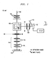
- FIG. 1 a diagram illustrates a LEEM/PEEM instrument without aberration correction or energy filtering.
- an electron gun generates an electron beam 102 at, for example, 15 keV electron energy.
- Condenser lenses 104 focus electron beam 102 into a magnetic deflector 106 having a specified prism array.
- Magnetic deflector 106 consists of two parallel plates, between which the electrons are deflected. Each plate of magnetic deflector 106 preferably contains at least one, but preferably five electromagnets. Magnetic deflector 106 deflects electron beam 102 over a large angle, for example, 90 degrees in this embodiment, thereby directing electron beam 102 to an objective lens system 108 for reflection from a sample 110.
- sample 110 may be illuminate with ultra violet (UV) light or soft X-ray photos 112 to generate photo electrons from sample 110.
- UV ultra violet
- soft X-ray photos 112 to generate photo electrons from sample 110.
- an electron gun is not utilized.
- Electrons from sample 110 form a diffraction pattern in a backfocal plane of objective lens system 108, as well as a real space image of sample 110 in a diagonal plane of the prism array of magnetic deflector 106.
- Magnetic deflector 106 Outside of magnetic deflector 106 exist four symmetric planes of special significance.
- An object placed in plane D1 of magnetic deflector 106 is transferred at unit magnification to plane D2 of magnetic deflector 106.
- the backfocal plane of objective lens system 108 is positioned to coincide with plane D1, enabling a diffraction pattern to be observed in plane D2.
- a real space magnified image of the sample is placed on the diagonal of magnetic deflector 106. This diagonal plane is achromatic.
- the diffraction pattern is energetically dispersed in plane D2, and not achromatic.
- a projector column 114 contains lenses 116 for magnification of the image from the diagonal plane of magnetic deflector 106 or the diffraction pattern from plane D2 of magnetic deflector 106 onto a viewing screen 118.
- FIG. 2 a diagram illustrates an aberration-correcting energy-filtering LEEM/PEEM instrument, according to an embodiment of the present invention.
- an electron gun generates an electron beam 202 as described above.
- Condenser lenses 204 and a magnetic field in a first magnetic deflector 206 also act in similar fashions to FIG. 1 .
- the deflection of electron beam 202 directs it into an objective lens system 208 and to a sample 210.
- the electrons After a reflection of electron beam 202 from sample 210, the electrons retrace their path to a final kinetic energy, preferably in the range 10-30 keV, forming a LEED pattern in a backfocal plane of objective lens system 208.
- a PEEM instrument may be utilized to generate a PED pattern in backfocal plane as described above.
- Backfocal plane of objective lens system 208 is positioned to coincide with plane A1 of first magnetic deflector 206, enabling a real space image to be formed on a diagonal of first magnetic deflector 206, and a diffraction pattern to be observed in plane A2 of first magnetic deflector 206 at unit magnification.
- Planes A1 and A2 are each equidistant from the center of first magnetic deflector 206, and are related to each other by 1:1 image transfers, by 90 degree deflection through the prism upon proper excitation of the array elements.
- Energy filtering of the real space image is partially provided through the placement of a suitable entrance slit 220 in plane A1, preferably taking a slice across the diffraction pattern.
- the width of entrance slit 220 will determine the achievable energy resolution in plane A2.
- the slice is reimaged by the prism array of first magnetic deflector 206 and also dispersed in energy.
- the prism array of first magnetic deflector 206 is of a simple, proven design that is easy to manufacture. It is double focusing for both image and diffraction planes.
- the image plane, located on the diagonal is preferably achromatic in this embodiment of the present invention.
- the diffraction plane, for the prism dimensions used has a dispersion of approximately 6 micrometer/eV in this embodiment of the present invention, sufficient for energy filtering and spectroscopy purposes.
- FIG. 3 a diagram illustrates aberration correction with dispersion, according to an embodiment of the present invention.
- the dispersed rays are not corrected. Instead, combination aberrations are introduced that are larger than the original aberrations.
- FIG. 4 a diagram illustrates aberration correction in the absence of dispersion, according to an embodiment of the present invention. Without dispersion, the aberrations of the mirror can correct the aberrations of the objective lens.
- a second magnetic deflector 222 substantially identical to first magnetic deflector 206, is disposed below first magnetic deflector 206 such that plane A2 of first magnetic deflector 206 coincides with plane B1 of second magnetic deflector 220. Additionally, an electrostatic lens 224 centered on the A2/B1 plane transfers the sample image from the diagonal plane of first magnetic deflector 206 onto the diagonal plane of second magnetic deflector 222 at unit magnification. After a 90 degree deflection through second magnetic deflector 222, the electron diffraction pattern is once again free from energy dispersion in plane B2 of second magnetic deflector 222, by virtue of symmetry.
- the embodiment of the present invention described above utilizes two substantially identical prism arrays or magnetic deflectors, separated by a simple electrostatic einzel lens operating at fixed focal length.
- An electrostatic lens is chosen, rather than a magnetic lens, to keep the image transfer rotation-free. Image rotation would spoil the cancellation of energy dispersion that results after the first 90 degree deflection by second magnetic deflector 222, setting up the proper ray paths to enter the electron mirror for aberration correction.
- An electron mirror 226, positioned beyond plane B2 of second magnetic deflector 222 corrects for both chromatic and spherical aberration.
- An auxiliary electrostatic lens system 228 between second magnetic deflector 222 and electron mirror 226 is set up to focus the electron diffraction pattern in plane B2 after aberration correction, and to focus the image on the diagonal plane of second magnetic deflector 222.
- the electron diffraction pattern is re-imaged by the prism array of second magnetic deflector 222 in plane B3, where the energy spectrum is once again dispersed.
- An exit aperture 228 in plane B3 is positioned to select a desired electron energy, and projector lenses 216 magnify the energy filtered real space image of sample 210 onto a viewing screen 218.
- FIG. 5 a diagram illustrates discrete energies at planes A1 and B3 of the electron microscopy instrument, according to an embodiment of the present invention.
- FIG. 5 assumes for simplicity that the energy spectrum of the electrons contains only two discrete energies E 1 and E 2 , with E 1 > E 2 . Due to the difference in energy the electron diffraction disc at E 1 is larger than at E 2 .
- plane A1 in FIG. 5 In the backfocal plane of the objective lens, plane A1 in FIG.
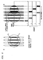
- FIG. 6 a diagram illustrates discrete energies at planes A1 and B3 of the electron microscopy instrument for different entrance aperture positions, according to an embodiment of the present invention.
- the dispersed lines corresponding to E 1 and E 2 are also scanned across B3.
- the projector lenses project B3 onto the viewing screen.
- the dispersed image of the slice in B3 may be recorded from the viewing screen with a video acquisition system, one image for each position of the entrance aperture.
- the complete diffraction discs for E 1 and E 2 can easily be reconstructed from these video recordings by digital computer, for both E 1 and E 2 .
- Microscope alignment is greatly simplified by the embodiment of the present invention provided above.
- Energy filtering requires only insertion of an appropriate slit in plane A1 and an appropriate aperture in plane B3, rather than deflection of the electron beam through a complex omega filter.
- second magnetic deflector 222 With second magnetic deflector 222 turned off, the electrons will travel straight down into the projector column, enabling alignment of first magnetic deflector 206 alone.
- second magnetic deflector 222 may be activated in two steps. First, 90 degree deflection is established by detecting electron beam 202 by passing it through an axial through-hole in electron mirror 226.
- first magnetic deflector 206 and second magnetic deflector 222 may be aligned and activated separately.
- FIG. 7 a diagram illustrates an aberration-correcting energy-filtering LEEM/PEEM instrument with neither magnetic deflector activated, according to an embodiment of the present invention.
- This mode of operation is selected to align the electron gun, condenser lenses, electrostatic lens and projector lenses, in a straight-column geometry, without the added complexity of deflections by first magnetic deflector 206 and second magnetic deflector 222.
- FIG. 8 a diagram illustrates an aberration-correcting energy-filtering LEEM/PEEM instrument with a first magnetic deflector activated, according to an embodiment of the present invention. Such an activation of the instrument would enable only energy filtering and not aberration correction. This mode of operation is selected to align first magnetic deflector 206 and objective lens systems relative to the straight column geometry of FIG.8 .
- FIG. 9 a diagram illustrates an aberration-correcting energy-filtering LEEM/PEEM instrument with a second magnetic deflector activated, according to an embodiment of the present invention.
- Such an activation of the instrument would enable only alignment of second magnetic deflector 222 and electron mirror optics, relative to the straight column geometry of FIG. 8 .
- FIG. 10 a flow diagram illustrates an energy-filtering aberration-correcting methodology for electron microscopy instruments, according to an embodiment of the present invention.
- the methodology begins in block 1002 where electrons are received at an objective lens in order to form an electron diffraction pattern in a backfocal plane of the objective lens.
- a slice of the electron diffraction pattern is filtered at an entrance aperture disposed in the backfocal plane of the objective lens.
- the slice of the electron diffraction pattern is received at a first magnetic deflector.
- the first magnetic deflector has an entrance plane and an exit plane. The entrance plane coincides with the entrance aperture.
- an energy dispersed electron diffraction pattern is transferred from a first magnetic deflector to a second magnetic deflector through an electrostatic lens disposed in an exit plane of the first magnetic deflector and an entrance plane of the second magnetic deflector.
- the second magnetic deflector is substantially identical to the first magnetic deflector.
- a non-dispersed electron diffraction pattern is projected from the second magnetic deflector to a first exit plane of the second magnetic deflector.
- the non-dispersed electron diffraction pattern is reflected in an electron mirror to correct one or more aberrations and return the nondispersed electron diffraction pattern to the second magnetic deflector.
- an energy dispersed electron diffraction pattern is projected in a second exit plane of the second magnetic deflector.
- a desired electron energy of the energy dispersed electron diffraction pattern is selected at an exit aperture disposed in the exit plane of the second magnetic deflector terminating the methodology.
- the embodiment of the present invention described above allows the electron column to maintain a vertical orientation, which is beneficial for mechanical stability reasons. Furthermore, the gun-to-screen axis remains a single straight line, greatly easing alignment of the key electron-optical components, including the condenser lens system, the prism-to-prism transfer lens, and the projector lens system.
- the embodiment of the present invention does not require a total redesign of the electron optical column.
- the second magnetic deflector is substantially identical to the first magnetic deflector.
- Energy filtering is accomplished by adding a single adjustable energy defining aperture strip to the system in plane A1, and an energy selection aperture in plane B3. This latter aperture also functions as the objective aperture. Only the electrostatic transfer lens and the electron mirror system need to be designed to realize the aberration correction function.
- the embodiment of the present invention described above has a high level of modularity. Both energy filtering and aberration correction can be retrofitted to the standard LEEM instrument by addition of the necessary components, without the need to modify other parts of the electron optical column.
Landscapes
- Chemical & Material Sciences (AREA)
- Analytical Chemistry (AREA)
- Analysing Materials By The Use Of Radiation (AREA)
- Electron Tubes For Measurement (AREA)
- Lenses (AREA)
- Electron Sources, Ion Sources (AREA)
- Investigating, Analyzing Materials By Fluorescence Or Luminescence (AREA)
Applications Claiming Priority (2)
| Application Number | Priority Date | Filing Date | Title |
|---|---|---|---|
| US11/364,299 US7348566B2 (en) | 2006-02-28 | 2006-02-28 | Aberration-correcting cathode lens microscopy instrument |
| PCT/US2007/062101 WO2007100978A2 (en) | 2006-02-28 | 2007-02-14 | Aberration-correcting cathode lens microscopy instrument |
Publications (2)
| Publication Number | Publication Date |
|---|---|
| EP1994544A2 EP1994544A2 (en) | 2008-11-26 |
| EP1994544B1 true EP1994544B1 (en) | 2010-06-30 |
Family
ID=38290996
Family Applications (1)
| Application Number | Title | Priority Date | Filing Date |
|---|---|---|---|
| EP07756958A Active EP1994544B1 (en) | 2006-02-28 | 2007-02-14 | Aberration-correcting cathode lens microscopy instrument |
Country Status (9)
| Country | Link |
|---|---|
| US (1) | US7348566B2 (enExample) |
| EP (1) | EP1994544B1 (enExample) |
| JP (1) | JP5147734B2 (enExample) |
| CN (1) | CN101390186B (enExample) |
| AT (1) | ATE472822T1 (enExample) |
| CA (1) | CA2636239C (enExample) |
| DE (1) | DE602007007446D1 (enExample) |
| IL (1) | IL193703A (enExample) |
| WO (1) | WO2007100978A2 (enExample) |
Cited By (1)
| Publication number | Priority date | Publication date | Assignee | Title |
|---|---|---|---|---|
| WO2024188471A1 (en) | 2023-03-16 | 2024-09-19 | Max-Planck-Gesellschaft zur Förderung der Wissenschaften e. V. | Electron microscopy apparatus and method for a time resolved low energy electron microscopy investigation of a sample |
Families Citing this family (29)
| Publication number | Priority date | Publication date | Assignee | Title |
|---|---|---|---|---|
| US7348566B2 (en) | 2006-02-28 | 2008-03-25 | International Business Machines Corporation | Aberration-correcting cathode lens microscopy instrument |
| RU2362234C1 (ru) | 2007-10-03 | 2009-07-20 | Вячеслав Данилович Саченко | Корпускулярно-оптическая система формирования изображения (варианты) |
| JP5250350B2 (ja) * | 2008-09-12 | 2013-07-31 | 株式会社日立ハイテクノロジーズ | 荷電粒子線応用装置 |
| DE102009044989A1 (de) * | 2009-09-24 | 2011-03-31 | Funnemann, Dietmar, Dr. | Bildgebender Energiefilter für elektrisch geladene Teilchen sowie Spektroskop mit einem solchen |
| EP2385542B1 (en) * | 2010-05-07 | 2013-01-02 | ICT Integrated Circuit Testing Gesellschaft für Halbleiterprüftechnik mbH | Electron beam device with dispersion compensation, and method of operating same |
| US9355818B2 (en) * | 2010-05-28 | 2016-05-31 | Kla-Tencor Corporation | Reflection electron beam projection lithography using an ExB separator |
| US9504135B2 (en) * | 2010-07-28 | 2016-11-22 | General Electric Company | Apparatus and method for magnetic control of an electron beam |
| CN102479652B (zh) * | 2010-11-30 | 2016-03-16 | 中国科学院大连化学物理研究所 | 采用紫外或深紫外激光源的高空间分辨光发射电子显微镜 |
| US8334508B1 (en) * | 2011-02-22 | 2012-12-18 | Electron Optica, Inc. | Mirror energy filter for electron beam apparatus |
| WO2013077715A1 (ru) * | 2011-11-22 | 2013-05-30 | Bimurzaev Seitkerim Bimurzaevich | Корректор аберраций электронных линз |
| US8586923B1 (en) * | 2012-06-21 | 2013-11-19 | International Business Machines Corporation | Low-voltage transmission electron microscopy |
| US8729466B1 (en) * | 2013-03-14 | 2014-05-20 | Electron Optica, Inc. | Aberration-corrected and energy-filtered low energy electron microscope with monochromatic dual beam illumination |
| EP2997590B1 (en) | 2013-05-15 | 2018-01-10 | Okinawa Institute of Science and Technology School Corporation | Leed for sem |
| US9595417B2 (en) * | 2014-12-22 | 2017-03-14 | ICT Integrated Circuit Testing Gesellschaft für Halbleiterprüftechnik mbH | High resolution charged particle beam device and method of operating the same |
| WO2016132487A1 (ja) | 2015-02-18 | 2016-08-25 | 株式会社日立製作所 | 荷電粒子線応用装置、及び、収差補正器 |
| DE102015210893B4 (de) * | 2015-06-15 | 2019-05-09 | Carl Zeiss Microscopy Gmbh | Analyseeinrichtung zur Analyse der Energie geladener Teilchen und Teilchenstrahlgerät mit einer Analyseeinrichtung |
| US9472373B1 (en) * | 2015-08-17 | 2016-10-18 | ICT Integrated Circuit Testing Gesellschaft für Halbleiterprüftechnik mbH | Beam separator device, charged particle beam device and methods of operating thereof |
| NL2017213B1 (en) * | 2016-07-22 | 2018-01-30 | Univ Delft Tech | Aberration correcting device for an electron microscope and an electron microscope comprising such a device |
| US10283315B2 (en) | 2017-05-16 | 2019-05-07 | International Business Machines Corporation | Measuring spherical and chromatic aberrations in cathode lens electrode microscopes |
| WO2019100600A1 (en) | 2017-11-21 | 2019-05-31 | Focus-Ebeam Technology (Beijing) Co., Ltd. | Low voltage scanning electron microscope and method for specimen observation |
| US10755892B2 (en) | 2018-05-23 | 2020-08-25 | Kla-Tencor Corporation | Reflection-mode electron-beam inspection using ptychographic imaging |
| CN112432933B (zh) * | 2019-08-26 | 2021-11-19 | 北京大学 | 多激发光源光电子显微镜的超高时空分辨成像系统及方法 |
| CN111194133B (zh) * | 2020-01-13 | 2022-01-11 | 电子科技大学 | 一种利用紫外辐射和电子枪产生中性尘埃粒子流的装置 |
| CN114220725B (zh) | 2020-12-02 | 2024-05-07 | 聚束科技(北京)有限公司 | 一种电子显微镜 |
| CN114256043B (zh) | 2020-12-02 | 2024-04-05 | 聚束科技(北京)有限公司 | 一种电子束系统 |
| US11264229B1 (en) | 2020-12-03 | 2022-03-01 | Guennadi Lebedev | Time-of-flight mass spectrometer and method for improving mass and spatial resolution of an image |
| JP7381515B2 (ja) | 2021-03-31 | 2023-11-15 | 株式会社日立ハイテク | 電子線応用装置 |
| JP7635103B2 (ja) | 2021-09-06 | 2025-02-25 | 株式会社日立ハイテク | 電子線応用装置及び検査方法 |
| CN118776445B (zh) * | 2023-04-07 | 2025-11-18 | 中国科学院大连化学物理研究所 | 自由电子激光中电子束与种子光到达时间抖动测量方法 |
Family Cites Families (7)
| Publication number | Priority date | Publication date | Assignee | Title |
|---|---|---|---|---|
| DE4129403A1 (de) * | 1991-09-04 | 1993-03-11 | Zeiss Carl Fa | Abbildungssystem fuer strahlung geladener teilchen mit spiegelkorrektor |
| EP0538938B1 (en) * | 1991-10-24 | 1996-08-28 | Koninklijke Philips Electronics N.V. | Electron beam apparatus |
| JPH11273610A (ja) * | 1998-03-23 | 1999-10-08 | Jeol Ltd | 高加速電圧反射電子顕微鏡 |
| JP2001319612A (ja) * | 2000-05-10 | 2001-11-16 | Jeol Ltd | 直接写像型電子顕微鏡 |
| DE10107910A1 (de) * | 2001-02-20 | 2002-08-22 | Leo Elektronenmikroskopie Gmbh | Teilchenstrahlsystem mit einem Spiegelkorrektor |
| US6878937B1 (en) * | 2004-02-10 | 2005-04-12 | Kla-Tencor Technologies Corporation | Prism array for electron beam inspection and defect review |
| US7348566B2 (en) | 2006-02-28 | 2008-03-25 | International Business Machines Corporation | Aberration-correcting cathode lens microscopy instrument |
-
2006
- 2006-02-28 US US11/364,299 patent/US7348566B2/en active Active
-
2007
- 2007-02-14 AT AT07756958T patent/ATE472822T1/de not_active IP Right Cessation
- 2007-02-14 JP JP2008557443A patent/JP5147734B2/ja active Active
- 2007-02-14 CN CN2007800068799A patent/CN101390186B/zh not_active Expired - Fee Related
- 2007-02-14 EP EP07756958A patent/EP1994544B1/en active Active
- 2007-02-14 WO PCT/US2007/062101 patent/WO2007100978A2/en not_active Ceased
- 2007-02-14 CA CA2636239A patent/CA2636239C/en active Active
- 2007-02-14 DE DE602007007446T patent/DE602007007446D1/de active Active
-
2008
- 2008-08-26 IL IL193703A patent/IL193703A/en not_active IP Right Cessation
Cited By (1)
| Publication number | Priority date | Publication date | Assignee | Title |
|---|---|---|---|---|
| WO2024188471A1 (en) | 2023-03-16 | 2024-09-19 | Max-Planck-Gesellschaft zur Förderung der Wissenschaften e. V. | Electron microscopy apparatus and method for a time resolved low energy electron microscopy investigation of a sample |
Also Published As
| Publication number | Publication date |
|---|---|
| DE602007007446D1 (de) | 2010-08-12 |
| WO2007100978A3 (en) | 2007-10-18 |
| CN101390186A (zh) | 2009-03-18 |
| JP2009528668A (ja) | 2009-08-06 |
| JP5147734B2 (ja) | 2013-02-20 |
| IL193703A (en) | 2011-11-30 |
| EP1994544A2 (en) | 2008-11-26 |
| ATE472822T1 (de) | 2010-07-15 |
| CA2636239C (en) | 2015-10-06 |
| CA2636239A1 (en) | 2007-07-09 |
| CN101390186B (zh) | 2011-02-16 |
| IL193703A0 (en) | 2009-05-04 |
| US7348566B2 (en) | 2008-03-25 |
| WO2007100978A2 (en) | 2007-09-07 |
| US20070200070A1 (en) | 2007-08-30 |
Similar Documents
| Publication | Publication Date | Title |
|---|---|---|
| EP1994544B1 (en) | Aberration-correcting cathode lens microscopy instrument | |
| US7947951B2 (en) | Multi-beam ion/electron spectra-microscope | |
| Tromp et al. | A new aberration-corrected, energy-filtered LEEM/PEEM instrument. I. Principles and design | |
| US6191423B1 (en) | Correction device for correcting the spherical aberration in particle-optical apparatus | |
| USRE33275E (en) | Electron Spectrometer | |
| EP1381073A1 (en) | Aberration-corrected charged-particle optical apparatus | |
| US8183526B1 (en) | Mirror monochromator for charged particle beam apparatus | |
| Rose | Prospects for realizing a sub-Å sub-eV resolution EFTEM | |
| US4978855A (en) | Electron microscope for investigation of surfaces of solid bodies | |
| US8334508B1 (en) | Mirror energy filter for electron beam apparatus | |
| US7453062B2 (en) | Energy-filtering cathode lens microscopy instrument | |
| US9018581B2 (en) | Transmission electron microscope | |
| EP0617453B1 (en) | Charged particle analyser | |
| Adamec et al. | Compact low-energy electron microscope for surface imaging | |
| US6441378B1 (en) | Magnetic energy filter | |
| JP4781211B2 (ja) | 電子線装置及びこれを用いたパターン評価方法 | |
| US11276549B1 (en) | Compact arrangement for aberration correction of electron lenses | |
| EP1585165B1 (en) | Electron microscope | |
| US7126117B2 (en) | Imaging energy filter for electrons and other electrically charged particles and method for energy filtration of the electrons and other electrically charged particles with the imaging energy filter in electro-optical devices | |
| Welnak et al. | SuperMAXIMUM: A Schwarzschild‐based, spectromicroscope for ELETTRA | |
| MacDowell et al. | Progress on PEEM3—An Aberration Corrected X‐Ray Photoemission Electron Microscope at the ALS | |
| Vašina et al. | X-ray photoemission and low-energy electron microscope |
Legal Events
| Date | Code | Title | Description |
|---|---|---|---|
| PUAI | Public reference made under article 153(3) epc to a published international application that has entered the european phase |
Free format text: ORIGINAL CODE: 0009012 |
|
| 17P | Request for examination filed |
Effective date: 20080918 |
|
| AK | Designated contracting states |
Kind code of ref document: A2 Designated state(s): AT BE BG CH CY CZ DE DK EE ES FI FR GB GR HU IE IS IT LI LT LU LV MC NL PL PT RO SE SI SK TR |
|
| 17Q | First examination report despatched |
Effective date: 20090306 |
|
| GRAP | Despatch of communication of intention to grant a patent |
Free format text: ORIGINAL CODE: EPIDOSNIGR1 |
|
| DAX | Request for extension of the european patent (deleted) | ||
| GRAS | Grant fee paid |
Free format text: ORIGINAL CODE: EPIDOSNIGR3 |
|
| GRAA | (expected) grant |
Free format text: ORIGINAL CODE: 0009210 |
|
| AK | Designated contracting states |
Kind code of ref document: B1 Designated state(s): AT BE BG CH CY CZ DE DK EE ES FI FR GB GR HU IE IS IT LI LT LU LV MC NL PL PT RO SE SI SK TR |
|
| REG | Reference to a national code |
Ref country code: CH Ref legal event code: NV Representative=s name: IBM RESEARCH GMBH ZURICH RESEARCH LABORATORY INTEL Ref country code: GB Ref legal event code: FG4D Ref country code: CH Ref legal event code: EP |
|
| REG | Reference to a national code |
Ref country code: IE Ref legal event code: FG4D |
|
| REF | Corresponds to: |
Ref document number: 602007007446 Country of ref document: DE Date of ref document: 20100812 Kind code of ref document: P |
|
| REG | Reference to a national code |
Ref country code: GB Ref legal event code: 746 Effective date: 20100716 |
|
| REG | Reference to a national code |
Ref country code: NL Ref legal event code: VDEP Effective date: 20100630 |
|
| PG25 | Lapsed in a contracting state [announced via postgrant information from national office to epo] |
Ref country code: SE Free format text: LAPSE BECAUSE OF FAILURE TO SUBMIT A TRANSLATION OF THE DESCRIPTION OR TO PAY THE FEE WITHIN THE PRESCRIBED TIME-LIMIT Effective date: 20100630 Ref country code: LT Free format text: LAPSE BECAUSE OF FAILURE TO SUBMIT A TRANSLATION OF THE DESCRIPTION OR TO PAY THE FEE WITHIN THE PRESCRIBED TIME-LIMIT Effective date: 20100630 |
|
| LTIE | Lt: invalidation of european patent or patent extension |
Effective date: 20100630 |
|
| PG25 | Lapsed in a contracting state [announced via postgrant information from national office to epo] |
Ref country code: SI Free format text: LAPSE BECAUSE OF FAILURE TO SUBMIT A TRANSLATION OF THE DESCRIPTION OR TO PAY THE FEE WITHIN THE PRESCRIBED TIME-LIMIT Effective date: 20100630 Ref country code: LV Free format text: LAPSE BECAUSE OF FAILURE TO SUBMIT A TRANSLATION OF THE DESCRIPTION OR TO PAY THE FEE WITHIN THE PRESCRIBED TIME-LIMIT Effective date: 20100630 Ref country code: FI Free format text: LAPSE BECAUSE OF FAILURE TO SUBMIT A TRANSLATION OF THE DESCRIPTION OR TO PAY THE FEE WITHIN THE PRESCRIBED TIME-LIMIT Effective date: 20100630 Ref country code: AT Free format text: LAPSE BECAUSE OF FAILURE TO SUBMIT A TRANSLATION OF THE DESCRIPTION OR TO PAY THE FEE WITHIN THE PRESCRIBED TIME-LIMIT Effective date: 20100630 |
|
| PG25 | Lapsed in a contracting state [announced via postgrant information from national office to epo] |
Ref country code: PL Free format text: LAPSE BECAUSE OF FAILURE TO SUBMIT A TRANSLATION OF THE DESCRIPTION OR TO PAY THE FEE WITHIN THE PRESCRIBED TIME-LIMIT Effective date: 20100630 |
|
| PG25 | Lapsed in a contracting state [announced via postgrant information from national office to epo] |
Ref country code: NL Free format text: LAPSE BECAUSE OF FAILURE TO SUBMIT A TRANSLATION OF THE DESCRIPTION OR TO PAY THE FEE WITHIN THE PRESCRIBED TIME-LIMIT Effective date: 20100630 Ref country code: EE Free format text: LAPSE BECAUSE OF FAILURE TO SUBMIT A TRANSLATION OF THE DESCRIPTION OR TO PAY THE FEE WITHIN THE PRESCRIBED TIME-LIMIT Effective date: 20100630 |
|
| PG25 | Lapsed in a contracting state [announced via postgrant information from national office to epo] |
Ref country code: SK Free format text: LAPSE BECAUSE OF FAILURE TO SUBMIT A TRANSLATION OF THE DESCRIPTION OR TO PAY THE FEE WITHIN THE PRESCRIBED TIME-LIMIT Effective date: 20100630 Ref country code: RO Free format text: LAPSE BECAUSE OF FAILURE TO SUBMIT A TRANSLATION OF THE DESCRIPTION OR TO PAY THE FEE WITHIN THE PRESCRIBED TIME-LIMIT Effective date: 20100630 Ref country code: PT Free format text: LAPSE BECAUSE OF FAILURE TO SUBMIT A TRANSLATION OF THE DESCRIPTION OR TO PAY THE FEE WITHIN THE PRESCRIBED TIME-LIMIT Effective date: 20101102 Ref country code: IS Free format text: LAPSE BECAUSE OF FAILURE TO SUBMIT A TRANSLATION OF THE DESCRIPTION OR TO PAY THE FEE WITHIN THE PRESCRIBED TIME-LIMIT Effective date: 20101030 Ref country code: CZ Free format text: LAPSE BECAUSE OF FAILURE TO SUBMIT A TRANSLATION OF THE DESCRIPTION OR TO PAY THE FEE WITHIN THE PRESCRIBED TIME-LIMIT Effective date: 20100630 Ref country code: CY Free format text: LAPSE BECAUSE OF FAILURE TO SUBMIT A TRANSLATION OF THE DESCRIPTION OR TO PAY THE FEE WITHIN THE PRESCRIBED TIME-LIMIT Effective date: 20100630 Ref country code: BE Free format text: LAPSE BECAUSE OF FAILURE TO SUBMIT A TRANSLATION OF THE DESCRIPTION OR TO PAY THE FEE WITHIN THE PRESCRIBED TIME-LIMIT Effective date: 20100630 |
|
| PG25 | Lapsed in a contracting state [announced via postgrant information from national office to epo] |
Ref country code: IT Free format text: LAPSE BECAUSE OF FAILURE TO SUBMIT A TRANSLATION OF THE DESCRIPTION OR TO PAY THE FEE WITHIN THE PRESCRIBED TIME-LIMIT Effective date: 20100630 |
|
| PG25 | Lapsed in a contracting state [announced via postgrant information from national office to epo] |
Ref country code: DK Free format text: LAPSE BECAUSE OF FAILURE TO SUBMIT A TRANSLATION OF THE DESCRIPTION OR TO PAY THE FEE WITHIN THE PRESCRIBED TIME-LIMIT Effective date: 20100630 |
|
| PLBE | No opposition filed within time limit |
Free format text: ORIGINAL CODE: 0009261 |
|
| STAA | Information on the status of an ep patent application or granted ep patent |
Free format text: STATUS: NO OPPOSITION FILED WITHIN TIME LIMIT |
|
| PG25 | Lapsed in a contracting state [announced via postgrant information from national office to epo] |
Ref country code: GR Free format text: LAPSE BECAUSE OF FAILURE TO SUBMIT A TRANSLATION OF THE DESCRIPTION OR TO PAY THE FEE WITHIN THE PRESCRIBED TIME-LIMIT Effective date: 20101001 |
|
| 26N | No opposition filed |
Effective date: 20110331 |
|
| PG25 | Lapsed in a contracting state [announced via postgrant information from national office to epo] |
Ref country code: ES Free format text: LAPSE BECAUSE OF FAILURE TO SUBMIT A TRANSLATION OF THE DESCRIPTION OR TO PAY THE FEE WITHIN THE PRESCRIBED TIME-LIMIT Effective date: 20101011 |
|
| REG | Reference to a national code |
Ref country code: DE Ref legal event code: R097 Ref document number: 602007007446 Country of ref document: DE Effective date: 20110330 |
|
| PG25 | Lapsed in a contracting state [announced via postgrant information from national office to epo] |
Ref country code: MC Free format text: LAPSE BECAUSE OF NON-PAYMENT OF DUE FEES Effective date: 20110228 |
|
| REG | Reference to a national code |
Ref country code: CH Ref legal event code: PL |
|
| PG25 | Lapsed in a contracting state [announced via postgrant information from national office to epo] |
Ref country code: LI Free format text: LAPSE BECAUSE OF NON-PAYMENT OF DUE FEES Effective date: 20110228 Ref country code: CH Free format text: LAPSE BECAUSE OF NON-PAYMENT OF DUE FEES Effective date: 20110228 |
|
| REG | Reference to a national code |
Ref country code: IE Ref legal event code: MM4A |
|
| PG25 | Lapsed in a contracting state [announced via postgrant information from national office to epo] |
Ref country code: IE Free format text: LAPSE BECAUSE OF NON-PAYMENT OF DUE FEES Effective date: 20110214 |
|
| PGFP | Annual fee paid to national office [announced via postgrant information from national office to epo] |
Ref country code: FR Payment date: 20120306 Year of fee payment: 6 |
|
| PG25 | Lapsed in a contracting state [announced via postgrant information from national office to epo] |
Ref country code: LU Free format text: LAPSE BECAUSE OF NON-PAYMENT OF DUE FEES Effective date: 20110214 |
|
| PG25 | Lapsed in a contracting state [announced via postgrant information from national office to epo] |
Ref country code: BG Free format text: LAPSE BECAUSE OF FAILURE TO SUBMIT A TRANSLATION OF THE DESCRIPTION OR TO PAY THE FEE WITHIN THE PRESCRIBED TIME-LIMIT Effective date: 20100930 Ref country code: TR Free format text: LAPSE BECAUSE OF FAILURE TO SUBMIT A TRANSLATION OF THE DESCRIPTION OR TO PAY THE FEE WITHIN THE PRESCRIBED TIME-LIMIT Effective date: 20100630 |
|
| PG25 | Lapsed in a contracting state [announced via postgrant information from national office to epo] |
Ref country code: HU Free format text: LAPSE BECAUSE OF FAILURE TO SUBMIT A TRANSLATION OF THE DESCRIPTION OR TO PAY THE FEE WITHIN THE PRESCRIBED TIME-LIMIT Effective date: 20100630 |
|
| REG | Reference to a national code |
Ref country code: FR Ref legal event code: ST Effective date: 20131031 |
|
| PG25 | Lapsed in a contracting state [announced via postgrant information from national office to epo] |
Ref country code: FR Free format text: LAPSE BECAUSE OF NON-PAYMENT OF DUE FEES Effective date: 20130228 |
|
| REG | Reference to a national code |
Ref country code: DE Ref legal event code: R082 Ref document number: 602007007446 Country of ref document: DE Representative=s name: KUISMA, SIRPA, FI |
|
| P01 | Opt-out of the competence of the unified patent court (upc) registered |
Effective date: 20230423 |
|
| PGFP | Annual fee paid to national office [announced via postgrant information from national office to epo] |
Ref country code: DE Payment date: 20240307 Year of fee payment: 18 |
|
| PGFP | Annual fee paid to national office [announced via postgrant information from national office to epo] |
Ref country code: GB Payment date: 20250226 Year of fee payment: 19 |
|
| REG | Reference to a national code |
Ref country code: DE Ref legal event code: R119 Ref document number: 602007007446 Country of ref document: DE |