EP1993644B1 - Inhalateur pour substances pulvérulentes - Google Patents
Inhalateur pour substances pulvérulentes Download PDFInfo
- Publication number
- EP1993644B1 EP1993644B1 EP07726709A EP07726709A EP1993644B1 EP 1993644 B1 EP1993644 B1 EP 1993644B1 EP 07726709 A EP07726709 A EP 07726709A EP 07726709 A EP07726709 A EP 07726709A EP 1993644 B1 EP1993644 B1 EP 1993644B1
- Authority
- EP
- European Patent Office
- Prior art keywords
- rod
- inhaler
- air flow
- inhaler according
- actuating button
- Prior art date
- Legal status (The legal status is an assumption and is not a legal conclusion. Google has not performed a legal analysis and makes no representation as to the accuracy of the status listed.)
- Not-in-force
Links
Images


Classifications
-
- A—HUMAN NECESSITIES
- A61—MEDICAL OR VETERINARY SCIENCE; HYGIENE
- A61M—DEVICES FOR INTRODUCING MEDIA INTO, OR ONTO, THE BODY; DEVICES FOR TRANSDUCING BODY MEDIA OR FOR TAKING MEDIA FROM THE BODY; DEVICES FOR PRODUCING OR ENDING SLEEP OR STUPOR
- A61M15/00—Inhalators
-
- A—HUMAN NECESSITIES
- A61—MEDICAL OR VETERINARY SCIENCE; HYGIENE
- A61M—DEVICES FOR INTRODUCING MEDIA INTO, OR ONTO, THE BODY; DEVICES FOR TRANSDUCING BODY MEDIA OR FOR TAKING MEDIA FROM THE BODY; DEVICES FOR PRODUCING OR ENDING SLEEP OR STUPOR
- A61M15/00—Inhalators
- A61M15/0065—Inhalators with dosage or measuring devices
- A61M15/0066—Inhalators with dosage or measuring devices with means for varying the dose size
-
- A—HUMAN NECESSITIES
- A61—MEDICAL OR VETERINARY SCIENCE; HYGIENE
- A61M—DEVICES FOR INTRODUCING MEDIA INTO, OR ONTO, THE BODY; DEVICES FOR TRANSDUCING BODY MEDIA OR FOR TAKING MEDIA FROM THE BODY; DEVICES FOR PRODUCING OR ENDING SLEEP OR STUPOR
- A61M15/00—Inhalators
- A61M15/0065—Inhalators with dosage or measuring devices
- A61M15/0068—Indicating or counting the number of dispensed doses or of remaining doses
- A61M15/007—Mechanical counters
- A61M15/0071—Mechanical counters having a display or indicator
- A61M15/0073—Mechanical counters having a display or indicator on a ring
-
- A—HUMAN NECESSITIES
- A61—MEDICAL OR VETERINARY SCIENCE; HYGIENE
- A61M—DEVICES FOR INTRODUCING MEDIA INTO, OR ONTO, THE BODY; DEVICES FOR TRANSDUCING BODY MEDIA OR FOR TAKING MEDIA FROM THE BODY; DEVICES FOR PRODUCING OR ENDING SLEEP OR STUPOR
- A61M2202/00—Special media to be introduced, removed or treated
- A61M2202/06—Solids
- A61M2202/062—Desiccants
-
- A—HUMAN NECESSITIES
- A61—MEDICAL OR VETERINARY SCIENCE; HYGIENE
- A61M—DEVICES FOR INTRODUCING MEDIA INTO, OR ONTO, THE BODY; DEVICES FOR TRANSDUCING BODY MEDIA OR FOR TAKING MEDIA FROM THE BODY; DEVICES FOR PRODUCING OR ENDING SLEEP OR STUPOR
- A61M2202/00—Special media to be introduced, removed or treated
- A61M2202/06—Solids
- A61M2202/064—Powder
-
- A—HUMAN NECESSITIES
- A61—MEDICAL OR VETERINARY SCIENCE; HYGIENE
- A61M—DEVICES FOR INTRODUCING MEDIA INTO, OR ONTO, THE BODY; DEVICES FOR TRANSDUCING BODY MEDIA OR FOR TAKING MEDIA FROM THE BODY; DEVICES FOR PRODUCING OR ENDING SLEEP OR STUPOR
- A61M2205/00—General characteristics of the apparatus
- A61M2205/10—General characteristics of the apparatus with powered movement mechanisms
- A61M2205/106—General characteristics of the apparatus with powered movement mechanisms reciprocating
Definitions
- the invention relates to an inhaler for powdery substances, in particular medicinal substances, with a substance storage chamber and a certain amount thereof receiving dosing, which is formed as a transverse bore of a rod and is displaceable from a filling position to a discharge position, in which emptying the dosing chamber in one Air flow channel is located.
- Inhalers of the type in question are known.
- an inhaler is shown and described, which has a, a metering chamber having rod which is displaceable from a filling position to a discharge position. This displacement to the emptying position is accomplished by a movement due to the negative pressure created by the patient's inhalation through the air flow channel. Dosierhuntverlagerung and emptying of the metering chamber is dependent on a suction by the patient in the course of a deep inhalation.
- WO01 / 21238 discloses an inhaler with a substance storage chamber and a metering chamber which is formed as a transverse bore of a flat bar and is displaceable from a filling position into a discharge position, in which emptying position the metering chamber is located in an air flow channel.
- the invention has the object to further improve a generic inhaler in particular with regard to the emptying of the metering chamber in the emptying position in an advantageous manner.
- the rod has a plurality of dosing chambers arranged one behind the other, which successively enter the emptying position during a dispensing operation and can be blown out piece by piece by an overpressure of air in the air flow channel are.
- an active emptying of each metering chamber is achieved.
- the Substance delivery is similar to that provided with acrosol cartridges inhalers. Due to the positive air pressure, the portioned substance is actively expelled from the metering chamber, being blown by machine guns by arranging a plurality of successive metering chambers which successively pass the emptying position in the longitudinal extent of a displacement of the metering chambers.
- An inhalation of the substance is due to the active blowing of the metering chamber or the metering reliably carried out even if, for example, the patient is not able to sufficiently high suction air flow to relocate and empty only a usually larger metering chamber, as in the prior art known to produce.
- a very fine distribution of the discharged substance is achieved by the Heildruckausblasung of the metering chambers, which in turn allows the use of micronized powder substances, which are set directly accessible to the lung.
- the metering chambers can be selected in such a size order that each chamber about 0.03 to 0.2 mg of substance can be received.
- the suction air flow necessary for the inhalation of the substance to be dispensed does not flow directly around or through the emptying area of the air flow channel, that is to say through the area provided with the metering chambers. Rather, the negative-pressure suction air stream is applied during inhalation only in the region of a mixing section to be assigned to the mouth or the nose, into which mixing section the partitioned substance is actively injected via the excess air pressure.
- the rod in a further development of the subject matter, provision is made for the rod to be designed as a flat rod having a length measured in cross section which corresponds to a multiple, for example ten times to twenty times the width measured transversely thereto.
- a rod is preferably provided with a thickness of about 0.3 to 0.7 mm, preferably 0.5 mm or 0.3 mm.
- the flat bar may consist of a plastic material, in particular of a hard plastic material. Preferred is a solution in which the flat bar is made of a metallic material.
- the metering chambers lying one behind the other in the longitudinal extent of the flat bar are provided in the simplest manner as circular-disk-shaped bores in the plan view, each having a center axis which is aligned perpendicular to the flat sides of the flat bar.
- the rod penetrates, in particular with the portion having the metering chambers, the substance storage chamber by dipping the stored in the storage chamber powdery substance.
- the storage chamber wall here preferably consists of an elastic material, for example of a rubber-like material, further for example of a thermoplastic elastomer.
- this elastically set reservoir chamber wall is arched in the direction of the rod and thus in the direction of the metering chambers. This is done first by an overpressure acting on the storage chamber wall from radially outside, which overpressure also serves for emptying the metering chambers in the emptying position. This overpressure is built up in the course of the inhaler actuation, preferably in the form of an air overpressure.
- the storage chamber wall bulges at least in the Dosierloch Scheme until it rests against the rod and thus causes a depression of the substance stored in the storage chamber into the metering chambers.
- vaulted state lie on each rod flat side, the respective opening cross sections of Dosing chamber facing, pantry wall sections on.
- the storage chamber wall sections act in the course of a displacement of the rod in the emptying position stripping. Such a stripping for exact portioning of the substance to be dispensed further preferably takes place before reaching the emptying position.
- the storage chamber wall is also arched in the direction of the rod in addition to the described pressurization.
- pressure pieces are provided which act from the outside on the storage chamber wall, for the preferred abutment of wall sections on the Stabflachchen. This active loading of the chamber wall by the pressure pieces further assists in the filling of the metering chambers formed in the centrally held rod.
- the metering chambers are preferably filled by means of the pressure pieces with Eisenschaitung the storage chamber wall still in the rest position of the rod. Only after this filling and concomitant completion of the idle stroke of the rod is entrained by further displacement of the actuating button to move the metering chambers in the emptying position.
- the plungers are preferably equipped with jaws, which have abutment surfaces which lie in fully pivoted or pressed position of the pressure pieces parallel to the broadside wall surface of the rod, resulting in One has the correct filling of the metering chambers result. Furthermore, a stripping position is thereby achieved.
- the baking-side abutment surfaces are formed in a plane spanning a plane.
- the actuating button of the inhaler is formed on the head side of the inhaler housing over this and displaceable against a return spring.
- the entire inhaler is preferably to be grasped between the thumb and, for example, the middle finger, with the middle finger resting on the actuating button and the thumb supporting a housing surface opposite the actuating button.
- the inhaler is actuated by pressing the actuating button, whereby the contact pieces are swiveled in the direction of the bar via bevels of the actuating button. After a short idle stroke, the actuating button pushes the rod in front of him under displacement of the metering chambers from the filling position in the storage chamber in the emptying position.
- the run-on slopes of the actuating button act accordingly pivoting on this.
- the plungers can also be arranged strictly linearly displaceable in the radial direction, this radial displacement is achieved by wedge effect to the rod out.
- the plungers are designed to be self-restoring especially in the case of a swivel design, in particular by a corresponding spring characteristic of the arms carrying the plungers.
- the pressure pieces move back to their original position after the lifting of the load acting on the ramps back to their original position, releasing the pantry wall, which latter returns due to the elastic properties back to the original position.
- an air pressure is built up which propagates by displacement of the rod to the air flow channel, specifically the adjoining in the flow direction of the rod part of the flow channel to blow out the substance. Accordingly, the overpressure is reduced at least in part only with a displacement of the metering chamber into the air flow channel while blowing out the substance. Further, according to the successive arrangement of several metering chambers in the rod and the accordingly successively connected connecting the respective metering chamber to the air flow channel, the partial reduction of the air pressure occurs under imposition of the substance from the respective metering staccato-like, what an optimal blowing of the substance and cloudy output to the environment and caused by the airflow generated by inhalation.
- the air pressure to be built up to be blown out is achieved by a piston / housing arrangement.
- This is achieved by an elastic piston ring at the inward end portion of the pot-shaped wall of the actuating button, which cooperates with an inner wall of the inhaler outer housing, which outer housing forms a corresponding compressed air cylinder for the piston ring.
- the actuating button itself forms the inner surface of the piston surface.
- the pressure pieces and the storage chamber are arranged in the region of the thus created compressed air cylinder, which assists the outside loading of the storage chamber and the displacement of the pressure pieces in the metering chamber filling position.
- the metering chambers having, linearly displaceable rod has a valve character.
- the cross section of the rod closes the air outlet in the region of the air flow channel, according to which, facing away from the output side of the air flow channel, the overpressure in the course of the downward displacement of the actuating button can build up. Only the retraction of a metering chamber of the rod in the air flow channel causes a valve-like opening and a corresponding Druck Kunststoffblasblasung. If the metering chambers are spaced apart in the direction of travel of the rod, a short-term one always takes place between the valve-opening-like blow-out phases of the metering chambers Closing the flow path through the rod material between two metering chamber.
- an air inlet valve is connected, which in the course of a spring-assisted backward displacement of the actuating button and corresponding increase in the created cylinder space air flows after, but is closed in the course of an active operation for dispensing an inhalation substance.
- an adjusting device for determining the number of bringable into the emptying position metering chambers is provided.
- a dosage is selectable, which limits the displacement of the rod in the longitudinal direction.
- dosing required only a few or more dosing chambers are spent in the Entleerüngs sued, that is in the field of compressed air Ausblasbeetzschlagung. Due to the small amounts of substance per metering chamber so a very accurate, variable dosage can be achieved.
- an accessible adjustment ring is provided, which is provided with a plurality of steps, for stopping the sliding movement of the actuating button. According to the stop-limited displacement of the button, a certain number of metering chambers pass through the emptying position.
- the operation key is provided with counter means, so preferably with a stop cam.
- a nozzle-like configuration By reducing the cross section of the air flow channel, in particular of the discharge end facing the end portion, a nozzle-like configuration can be achieved.
- a reduced cross section of an air flow passage end portion corresponds to about 0.5 to 0.9 times the original cross section.
- the rectilinearly transverse air flow channel continues into a cross-section smaller, obliquely upward end channel section, which ends within a nose spout set back to the free end. Due to this configuration, the proposed inhaler is also applicable to nasal application. Due to the active emptying of the dosing chambers, the drug to be inhaled is deliberately blown into the nasal cavity.
- the simultaneous inhalation through the nose advantageously supports the redistribution of the drug. Due to the obliquely upward orientation of the Endkanalabitess and thus also this Endkanalabrough receiving nasal nozzle of the inhaler is conveniently applicable, so on, if necessary, under approximately vertical orientation of the inhaler during the inhalation process.
- an actuated upon reaching the Ausblas Kunststoffscheres stepping mechanism is provided.
- Such a stepper mechanism counts every single operation of the inhaler, in which a drug delivery takes place.
- a stepper has a scale, such as a scale ring on which either the already performed inhalation operations are displayed or alternatively counting down from a maximum inhalation number indicating the still available inhalation shots.
- the derailleur is operated in response to reaching the Ausblas Kunststoffbuches, which Ausblas Kunststoffbuch immediately before reaching the filled Dosing is constructed in the transfer area to the air flow channel.
- the stepper is switched just prior to transfer of the drug into the air flow channel and, correspondingly, immediately prior to active purging of the drug. If, however, the handle is actuated only to the extent that it does not come to a imposition of the drug, that is, possibly only to a filling of the metering chambers and thereafter successful Wiederrückverlagerung the handle, there is no circuit of the stepper.
- This is achieved in an exemplary embodiment by a counting finger acting on the stepping mechanism, the tip of which reaches the stepping wheel of the stepping mechanism approximately at the beginning of the displacement of the rod with the filled metering chambers in the area of the air flow channel.
- the counting finger is positioned correspondingly at a distance from the stepping wheel, which distance is overcome by handling the handle with concomitant displacement of the metering chambers having the rod at the same time building up the Ausblas Kunststoffbuches.
- the display of the stepping mechanism is in a preferred embodiment, a concentric to the inhaler aligned graduated ring, which is formed like a tooth-like inside on the stepwise displacement in the circumferential direction of rotation, for cooperation with the indexing gear.
- the latter is formed in a preferred embodiment in such a way that it rotates the scale ring of the stepping mechanism like a worm wheel. Accordingly, there is no need for any further intermediate translations to implement the stepping finger operation of the indexing wheel, which takes place from a linear movement, into a circular movement directed transversely to the axis.
- the transmission to the scale ring can be sub-translated or translated depending on the particular design of the stepper.
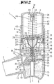
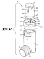
- an inhaler 1 which is implemented as a conveniently portable pocket device, with a cylindrical housing 2, of which an approximately radially projecting mouthpiece 3 goes out.
- the general form of the inhaler 1 substantially corresponds to that of the acrosolubular inhalers. Accordingly, the course of action of the inhaler 1 is transmitted and immediately recognizable to the user.
- the inhaler 1 has a general housing axis x receiving, transverse to this axis x aligned and projecting beyond the housing 2 actuating button 4, which faces a housing foot side counter surface 5.
- the housing 2 is formed in the form of a hollow cylindrical body, with a circular plan in the illustrated embodiment.
- Other shapes deviating from this circular plan shape are also conceivable, such as, for example, elliptical or polygonal ones.
- the circular cylindrical inhaler outer housing 6 is closed at the foot by an inhaler bottom 7, which forms the mating surface 5 for actuating the inhaler 1.
- the housing 2 is designed to be open.
- the mouthpiece 3 which is formed substantially as a hollow cylinder body, with a with respect to the orientation of the mouthpiece 3 to axially outwardly facing mouth.
- a arranged in the transition region of the housing 2 in the mouthpiece 3 mouthpiece bottom 8 has a central opening. 9 With axial distance to this central bottom opening 9 evenly distributed air inlet openings 10 are formed in the Mund Glafflendung along a circumferential line, for air flow connection of the bottom opening 9 associated Mund Swississeraumes to the environment.
- the mouthpiece 3 is covered by a screw cap 11 when the inhaler 1 is not in use.
- the mouthpiece 3 mantelau fieldwandig is provided with an external thread 12 which cooperates with an internal thread 13 of the cap 11.
- the jacket section of the screw cap 11 having the internal thread 13 traps over the air inflow openings 10 of the mouthpiece 3, wherein furthermore the end ring surface of this jacket section of the screw cap 11 abuts against a housing section in a stop-limited manner.
- the housing 2 is divided transversely to the housing axis x by an attached to the housing inner wall at the level of the transition from the housing to the mouthpiece 3 carrier 14. It results in accordance with a reference to the carrier 14 upper housing portion and a lower, the counter surface 5 associated portion, which latter is centrally penetrated by an axially extending support tube 15, on which the carrier 14 is seated. In the thus created annular space in the lower housing portion, a moisture absorbing material 16 is added. Furthermore, this annular space 17 is connected via a Nachströmö réelle 18 which is formed in the region of the mouthpiece bottom 8, with the cylinder interior of the mouthpiece 3 and via the Heileinströmötechnischen 10 with the environment in connection.
- the disc-shaped, solid carrier 14 has a central receptacle 19 into which a sealing element 20 made of a thermoplastic material is inserted.
- This sealing element 20 sits like a plug in the receptacle 19, wherein further the carrier 14 is supported on the tube 15 via this sealing element 20.
- the sealing element 20 is provided with a substantially rectilinear transverse to the axis x aligned air flow channel 21, which is on both sides, the carrier 14 each passing through, continued.
- the air flow channel 21 on the one hand of the sealing element 20 extends through the carrier 14 through to the central opening 9 of the mouthpiece bottom 8, to form an air outlet 22.
- the air flow channel 21 is under extension of its cross-section towards continued through the carrier 14 separated upper housing section.
- the corresponding channel opening 23 is formed on the upper housing section facing broad surface of the carrier 14, wherein further this channel mouth 23 is covered by a filter element 24.
- the air flow passage 21 is thus divided into a mouthpiece side passage portion and a case side portion. In the latter, the filter-covered channel mouth 23 is formed. Further, in this section, a channel mouth 23 opposite Nachströmö réelle 25 is arranged, which forms a connection between the housing-side portion of the air flow passage 21 and the underside of the carrier 14 formed annular space 17.
- This Nachströmö réelle 25 is covered by an air inlet valve 26 which is connected so that the Nachströmö réelle 25 is opened only in an air flow from the annular space 17 through the air flow passage 21 in the direction of the upper housing portion. In the opposite direction of air flow, the valve 26 closes this Nachströmö réelle 25th
- the air flow channel 21, in particular in the region of the sealing element 20 and the mouthpiece 3 facing portion is dimensioned substantially smaller than the free cross section of the mouthpiece 3.
- the free interior diameter of the mouthpiece 3 corresponds to about ten to thirty times the diameter of the air flow channel 21, which latter in particular starting is formed by the sealing element 20 in the direction of the mouthpiece-side opening 9 in the region of an obliquely downwardly extending portion tapering towards the formation of a nozzle-like channel.
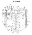
- the sealing element 20 goes in one piece, of the same material over in a the upper housing section facing funnel-shaped storage chamber 27, with upwards, that is in the direction of the frontal housing opening towards expanding cross-section.
- the storage chamber wall 28 accordingly also consists of a thermoplastic. Elastomer or other rubbery material.
- the diameter-extended free end of the storage chamber 27 is detected by a transversely to the inhaler x aligned holder 29, which is laterally of the storage chamber 27 extending, oppositely arranged supports 30 at the lower end of the storage chamber 27 holding carrier 14 is attached. Accordingly, the axial distance of the storage chamber ends is fixed to each other.
- the upper free end of the storage chamber 27 is sealed in the holder 29, so clamped in the illustrated embodiment between a radially outer retaining ring 31 and a radially inner, plug-like HaIteabites 32nd
- a micronized powdery substance 33 is stored, which is to be inhaled by the proposed device in portioned output.
- metering chambers 34 are provided, thus in the illustrated first embodiment of the three.
- the size of a Each metering chamber 34 defines the respective amount of substance to be discharged.
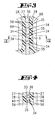
- the metering chambers 34 are formed as transverse bores 35 of a rod 36 formed as a flat rod and extending centrally along the axis x.
- the transverse bores 35 in this case pass through the wide side wall surfaces of the flat bar 36, wherein this further has a width / length ratio of 1: 5 to 1: 20 in cross section.
- a flat bar thickness of about 0.5 mm is selected, with a measured transversely thereto length of about 3 to 3.5 mm.
- the transverse bores 35 are selected in their diameter such that each dosing chamber 34 formed thereby receives a substance amount of 0.05 mg to 0.1 mg.
- the rod 36 with the metering chambers 34 passes through the storage chamber 27 centrally in the direction of extension of the axis x.
- the rod 36 passes through the sealing element 20 while crossing the formed in this air flow channel 21, according to this embodiment by means of the rod 36, a closure of the air flow passage 21 is first reached.
- the rod 36 extends beyond the storage chamber 27, under enforcement of the storage chamber 27 defining holder 29.
- a further sealing element 37 is arranged, which as well as the sealing element 20 in the foot-side region of the storage chamber 27 stripping acting on the surfaces of the rod 36, with simultaneous sealing of the enforcement zones.
- the uniformly spaced in longitudinal extension of the rod 36, arranged one behind the other metering chambers 34 are in a basic position of the inhaler 1 as shown in FIG FIG. 1 positioned in the lower third of the storage chamber 27, enclosed by the stored substance 33rd
- the distance of the metering chambers 34 to each other substantially corresponds approximately to the diameter of a metering chamber 34 forming a transverse bore 35th
- the upwardly beyond the storage chamber 27 also protruding free end of the rod 36 is provided with a mushroom-like driver 38.
- This is detected by underside of the actuating button 4 integrally formed towing arms 39, which have a length which corresponds approximately to twice the length of the driver 38 in the direction of extension of the axis x.
- an idle stroke is created between the actuating button 4 facing the tip of the driver 38 and the corresponding corresponding to the underside driving surface 40 of the actuating button. 4
- the actuating button 4 extending essentially transversely to the inhaler axis x passes over a cylinder-like section which is formed concentrically with the axis x and has a cup-shaped wall 41 which, with its opening facing downwards, dips into the housing 2.
- the outer diameter of the wall 41 is adapted to the inner diameter of the housing cylinder section 6 accordingly.
- the actuating button 4 is inserted with its wall 41 under guidance by the cylinder portion 6 in the housing 2, this at stop limit in the respective end positions.
- housing cylinder section 6 in the region of its free edge portion on two diametrically opposite, radially inwardly facing guide lugs 42 which engage in axially parallel grooves 43 in the region of the outer jacket 41 of the wall.
- annular groove 44 is provided for receiving an existing elastomeric piston ring 45, which occurs to seal against the inner wall of the housing cylinder section 6.
- the operating key basic position as shown in FIG. 1 is supported by a force acting on the underside of the actuating button 4 return coil spring 46, the other end of the rod 36 and the drag arms 39 of the actuating button 4 is supported on the head end of the storage chamber 27 forming holder 29.
- This basic position is defined by striking the guide lugs 42 at the lower end of the actuation key-side grooves 43, wherein further in this basic position of the rod-side driver 38 occupies a maximum distance to the driving surface 40 of the actuating button 4.
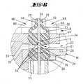
- Wedge-shaped Aus Wegvorsprünge 47 occur in the displacement of the operating button wall 41 with upwardly facing ramps 61 of two diametrically opposed, in the foot-side free end portion radially inwardly projecting plungers 48 supporting arms 49.
- These provided with the pressure pieces 48 arms 49 are with respect to a Floor plan offset by 90 ° to the support 29 carrying the supports 30 positioned; further attached to these via a circular in plan view carrier on the holder 2.
- the arms 49 and the radially inwardly facing abutting surfaces 50 of the jaws 60 forming pressure pieces 48 extend in a plan or in a cross section through the inhaler 1 parallel spaced to a broad side surface of the rod 36. Accordingly, the abutment surfaces 50 are the broad side surfaces of the bar 36th positioned facing, wherein further the abutting surfaces 50 are each formed flat.
- the arms 49, in particular the articulation regions 51 on the annular carrier are selected with regard to the choice of material and / or with regard to the material thickness so that a radial pivoting in the direction of the axis x is allowed around the articulation regions 51.
- the spring properties of the selected plastic material are used for the automatic return of the arms 49 in the original position.
- the length of the arms 49 measured in the axial direction is selected such that the pressure pieces 48 provided at the end extend approximately at the level of the lower third of the storage chamber 27.
- the operation of the inhaler 1 is as follows:
- the substance present in the basic position of the inhaler 1 on both sides of the metering chamber openings is forced into the transverse bores 35 by means of the storage chamber wall 28 and the pressure pieces 48 acting thereon, after which latching is provided in the metering chambers 34, particularly in the case of a micronized powder substance.
- the concavity of the storage chamber wall 28 for pressing the substance into the metering chambers 34 is supported by the build-up in the course of this process air pressure in the compressed air cylinder D.
- the axially deflecting downward free end of the rod 36 occurs in the course of downward displacement in the interior of the support tube 15 a.
- the considered in Downward displacement direction end position of the actuating button 4 is also stop limited. This is achieved by striking the guide lugs 42 against the upper edge region of the grooves 43 interacting with them and / or by stepping the free annular end face of the actuating button wall 41 against the surface of the carrier 14.
- the inhaler 1 in particular the housing and the actuating button 4 with the wall 41 and the holder 29 with the carrier fourteenth , made of a plastic material, more particularly made of a hard plastic material.
- the rod 36 may consist of such a hard plastic material.
- a rod 36 made of a metal material is preferred.
- the inhaler 1 shaped for oral treatment is also conceivable in a design for nasal inhalation. Like, for example, in FIG. 12 shown.
- the discharge area is directed obliquely upwardly with respect to the vertical axis x, thus including an angle to the longitudinal axis x of about 45 °.
- the housing 2 is provided with a nasal nozzle 65 which, when the inhaler 1 is not used, is covered by a screw cap 11 in accordance with the previously described embodiment.
- the nasal nozzle 65 is adapted in its longitudinal extension and in its outer diameter for insertion into a nostril. Centrally in the longitudinal extent of the nose spout 65 this is penetrated by an output channel 66. In this opens a Endkanalab songs 67 of the air flow channel 21, the free end 68 is set back, is placed correspondingly with respect to the Nasentüllen body axis axially rearwardly displaced to the free end 69 of the nose spout 65.
- the end channel section 67 also extends obliquely upward starting from the transversely directed straight air flow channel 21, reducing the free cross section with respect to the cross section of the air flow channel 21 by approximately one third , which allows a nozzle-like configuration of the Endkanalabitess 67.
- the annular adjustment device 52 is provided with diametrically opposed Jardines 53, which are formed by radially inwardly projecting window 54 of the housing 2 by passing.
- Each step body 53 is provided with staggered stop surfaces 55.
- the number of step surfaces corresponds to the number of Dosiereinstella.
- These abutment surfaces 55 cooperate with correspondingly diametrically opposite to the outer surface of the wall 41 arranged cam 56. These are guided in correspondingly positioned grooves 57 inwardly of the housing cylinder section 6 and secured against rotation relative to the housing 2.
- a downward in the direction of insertion of the actuating button 4 facing cam surface 58 occurs upon actuation against the screwed into the displacement path of the cam 56 abutment surface 55 of the step body 53, whereby the sliding movement of the actuating button 4 is stopped.
- the displacement of the rod 36 provided in this exemplary embodiment with five metering chambers 34 arranged one behind the other is also stop-limited, according to which the number of metering chambers 34 to be brought into the emptying position E can be preselected as a function of the setting via the stepped stops.
- only two metering chambers 34 or only the first metering chamber 34 can be connected to the air flow channel 21 and can be blown out by means of pressurized air upon actuation of the inhaler 1.
- all metering chambers 34 as shown, five metering chambers 34, are successively supplied to the air flow channel 21 and their substance portions are imposed in a salve manner.
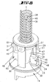
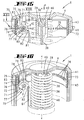
- FIGS. 13 to 19 show in another embodiment, an inhaler 1, which is first formed according to the first embodiment as an oral inhaler. It is a stepper 70 provided for registration and Display of performed inhalation procedures.
- This stepping mechanism 70 is arranged in the above the housing 2 above actuating button 4, so further immediately below the ceiling of the actuating button 4, surrounding the driver 38 of the rod 36 associated drag arms 39.
- the stepping mechanism 70 consists essentially of a stepping gear 71 and a scale ring 72 which is in positive engagement with the stepping gear 71.
- the scale ring 72 is arranged cuff-like immediately below the operating ceiling, so on concentric with the housing axis x.
- the encircling scale ring wall is located in a radial extension of the wall 41 of the actuating button 4, according to a rotation about the housing axis x held in this radial receptacle 73 of the wall 41 permitting.
- Cloak outside the scale ring 72 is provided with a scale 74, not shown, so for example printed with such.
- This scale 64 is visible through a window 75 provided on the wall side in the transitional area of the wall 41 into the ceiling of the actuating button 4.
- Sheath inside of the scale ring 72 is provided in the center of the vertical extension with radially projecting driving projections 76. It is viewed over the circumference while maintaining uniform distances from one another a plurality of such driving projections 76 are provided, so for example, a number corresponding to the maximum number of inhalation firing. In the illustrated embodiment, however, a much smaller number is selected.
- the entrainment of the scale ring 72 on the projections 76 is here stocky.
- the Schwarzrad 71 acts positively with these driving projections 76 together, the Shaschaltrad 71 to a transverse to the housing axis x aligned rotational axis y is rotatable, which axis y extends in the plane defined by the driving projections 76 plane.
- the axis y is released by an axle body 77, which is gripped on both sides at the end in support arms 78 which project inwards from the bed of loading bed.
- the indexing gear 71 is substantially formed as a single-turn worm shaft 79 with a helical pitch, which is adapted to the spacing of two adjacent driving projections 76 in the circumferential direction.
- the worm shaft 79 is viewed in the axial direction of the same provided with such a length that results in a total of substantially two to three worm spiral sections.
- the respective associated driving projection 76 occurs at shaft height of the stepping wheel 71 between the flanks of the screw helix.
- each tooth 80 has a steep edge, oriented approximately at a radial edge and the rear thereof has a flat towards the subsequent tooth 80 sloping edge.
- nine teeth 80 are formed in the cross section through the Schwarzschaltrad 71 over the circumference, which are further dimensioned so that in transverse consideration, d. H. viewed in alignment of the axis y, the teeth 80 of a helical section in horizontal projection are in register with the teeth 80 of the adjacent helix section.
- the respective tooth flanks of adjacent helix sections are also aligned in a common plane.
- the teeth 80 cooperate with a counting finger 81 which, viewed parallel to the axis of rotation y of the indexing gear 71, is in the free end region, that is to say in the operating end portion 82 cooperating with the stepping wheel 71 has a width which corresponds approximately to the width of the stepping wheel 71 measured in the same direction.
- the Zählfinger 81 is rooted in the arms 49 of the plungers 48 supporting annular support and grows rod-like parallel alignment with the housing axis x upwards in the direction of the basic position as shown in FIG. 13 vertically spaced stepping gear 71 from, this under end-molding of the above-described, a tip-forming operating portion 82nd
- the vertical distance between the operating portion 82 of the Zählfingers 81 and to be actuated steep flank of a radially inwardly facing tooth 80 of the Shaschaltrades 71 is corresponding to the stroke of the actuating button 4, starting from the basic position in FIG. 13 to the transfer position of the drug from the filled metering chamber 34 into the air flow passage 21 as shown in FIG FIG. 5 respectively.
- FIG. 6 selected.
- the stepper 70 is only then actuated, that is switched by one position, when in the course of the downward displacement of the actuating button 4, first filling the metering chambers 34 carried out on the plungers 48 and hereafter with further downward displacement of the actuating button 4 for the sudden blowing out of the metering chambers 34 required Ausblas Kunststofftik is reached.
- the metering chambers 34 in the region of the air flow passage 21, through which the substance is suddenly blown out due to the built-up air pressure.
- This further vertically downward actuation displacement of the key 4 leads to a rotational displacement of the indexing gear 71 about a toothed segment.
- the rearwardly provided flat rising tooth flanks allow the sliding of the operating portion 82 in return displacement of the actuating button 4 in the normal position.
- the inhaler may contain various drugs and / or bioactive substances for inhalation.
- any therapeutic or diagnostic agent may be selected, for example from the group of antiallergic agents, bronchodilators, bronchoconstrictors, lung surfactants, analgesics, antibiotics, leukotriene inhibitors or antagonists, anticholinergics, mast cell inhibitors, antihistamines, antiphlogistics, antineoplastic agents, anesthetics, antituberculosis agents, contrast agents , cardiovascular agents, enzymes, steroids, genetic material, viral vectors, antisense reagents, proteins or peptides, and combinations of these substances.
- Examples of specific drugs with which the inhaler according to the patent specification can be filled are u. a. Mometasone, ipratropium bromide, tiotropium and its salts, salmeterol, fluticasone propionate, beclomethasone dipropionate, reproterol, clenbuterol, rofleponide and its salts, nedocromil, sodium cromoglycate, flunisolide, budesonide, formoterol fumarate dihydrate, Symbicort® (budesonide and formoterol), terbutaline, terbutaline sulfate, salbutamol base and sulfate , Fenoterol, 3- [2- (4-hydroxy-2-oxo-3H-1,3-benzothiazol-7-yl) ethylamine] - N - [2- [2- (4-methylphenyl) ethoxy] ethyl] propanesulfonamide , Hydroch
- medicament combinations for example formoterol / budesonide; Formoterol / FluHcason; Formoterol / mometasone; Salmetcrol / fluticasone; Formoterol / tiotropium salts; Zafirlukast / formoterol, zafirlukast / budesonide; Montelukast / Formotcrol; Montelukast / budesonide; Loratadin / Montelukast and Loratadin / Zafirlukast.
- formoterol / budesonide for example formoterol / budesonide; Formoterol / FluHcason; Formoterol / mometasone; Salmetcrol / fluticasone; Formoterol / tiotropium salts; Zafirlukast / formoterol, zafirlukast / budesonide
- Tiotropium and fluticasone Tiotropium and fluticasone, tiotropium and budesonide, tiotropium and mometasone, mometasone and salmeterol, formoterol and rofleponide, salmeterol and budesonide, salmeterol and rofleponide, and tiotropium and rofleponide.
Landscapes
- Health & Medical Sciences (AREA)
- Engineering & Computer Science (AREA)
- Life Sciences & Earth Sciences (AREA)
- Animal Behavior & Ethology (AREA)
- Public Health (AREA)
- Pulmonology (AREA)
- Anesthesiology (AREA)
- Biomedical Technology (AREA)
- Heart & Thoracic Surgery (AREA)
- Hematology (AREA)
- Veterinary Medicine (AREA)
- General Health & Medical Sciences (AREA)
- Bioinformatics & Cheminformatics (AREA)
- Biophysics (AREA)
- Containers And Packaging Bodies Having A Special Means To Remove Contents (AREA)
- Organic Low-Molecular-Weight Compounds And Preparation Thereof (AREA)
- Medicinal Preparation (AREA)
- Medical Preparation Storing Or Oral Administration Devices (AREA)
- Centrifugal Separators (AREA)
- Infusion, Injection, And Reservoir Apparatuses (AREA)
Claims (14)
- Inhalateur (1) pour substances (33) pulvérulentes, en particulier substances médicinales, avec une chambre de stockage de substance (27) et une chambre de dosage (34), recevant une quantité déterminée de celles-ci, réalisée sous la forme de perçage transversal (35) d'une barre (36), et susceptible d'être déplacée d'une position de remplissage (B) en une position de vidage (E), position de vidage (E) dans laquelle la chambre de dosage (34) est située dans un canal d'écoulement d'air (21), caractérisé en ce que la barre (36) comprend plusieurs chambres de dosage (34), situées les unes derrière les autres sur la barre (36), qui, pendant un actionnement de distribution individuel, passent les unes après les autres à la position de vidage (E) et sont susceptibles d'être soumises à une chasse par soufflage, une par une, par une surpression d'air dans le canal d'écoulement d'air (21).
- Inhalateur selon la revendication 1, caractérisé par une course à vide, entre une touche d'actionnement d'inhalateur (4) et la barre (36), de manière que, avant l'entraînement de la barre (36), une incurvation d'une paroi de chambre de stockage (28) se produise au moyen de pièces de pressage (48) extérieures.
- Inhalateur selon la revendication 2, caractérisé en ce que la barre (36) est réalisée sous la forme de barre plate, et les pièces de pressage (48) sont équipées de mâchoires (60) comprenant des faces de joint (50) qui, lorsque les pièces de pressage (48) sont complètement escamotées par pivotement, sont situées parallèlement à la surface de paroi de côté large de la barre plate (36).
- Inhalateur selon une ou plusieurs des revendications 2 et 3, caractérisé en ce que la touche d'actionnement (4) fait saillie, côté tête, du boîtier d'inhalateur (2), est déplaçable à l'encontre d'un ressort de rappel (46) et, après une courte course à vide, ramène par poussée devant soi la barre (36), et fait pivoter, sur des chanfreins de franchissement (61), les pièces de pressage (48) en direction de la barre (36).
- Inhalateur selon une ou plusieurs des revendications 2 à 4 précédentes, caractérisé en ce que, lors de l'actionnement de l'inhalateur (1), la paroi de chambre de stockage (28), composée de matériau élastique, s'incurve en direction de la barre (36), au moins dans la zone de trou de dosage, jusqu'à venir en appui sur la barre (36).
- Inhalateur selon une ou plusieurs des revendications 2 à 5 précédentes, caractérisé en ce que, en cas de déplacement de la touche d'actionnement (4), dans le boîtier d'inhalateur (2) s'établit une surpression d'air qui, lors du déplacement de la barre (36), se propage dans le canal d'écoulement d'air (21), pour aboutir à la chasse par soufflage de la substance (33).
- Inhalateur selon une ou plusieurs des revendications 2 à 6 précédentes, caractérisé par un segment de piston (45) élastique, sur la zone d'extrémité située intérieurement, d'une paroi (41), en forme de pot, de la touche d'actionnement (4), le boîtier extérieur de l'inhalateur (2) formant, avec sa paroi intérieure, le cylindre à pression (D) pour ce segment de piston (45).
- Inhalateur selon une ou plusieurs des revendications précédentes, caractérisé en ce que la section transversale de la barre (36) obture un échappement d'air.
- Inhalateur selon une ou plusieurs des revendications précédentes, caractérisé par un dispositif de réglage (52), pour déterminer le nombre des chambres de dosage (34) susceptibles d'être placées à la position de vidage (E).
- Inhalateur selon une ou plusieurs des revendications 2 à 9 précédentes, caractérisé par une bague de réglage (62), avec plusieurs degrés pour stopper le déplacement de la touche d'actionnement (4) après passage d'un nombre déterminé de chambres de dosage (34) par la position de vidage (E).
- Inhalateur selon une ou plusieurs des revendications précédentes, caractérisé en ce que le canal d'écoulement d'air (21), orienté transversalement et rectiligne, se prolonge en un tronçon de canal d'extrémité (67) à plus petite section transversale, orienté obliquement vers le haut, qui s'achève à l'intérieur d'un bec de nez (65), en retrait de son extrémité (69) libre.
- Inhalateur selon une ou plusieurs des revendications précédentes, caractérisé par un mécanisme de commutation pas à pas (70), actionné à l'atteinte de la pression d'air de soufflage.
- Inhalateur selon la revendication 12, caractérisé par un doigt de comptage (81), agissant sur le mécanisme de commutation pas à pas (70), dont la pointe (82) atteint une roue de commutation pas-à-pas (71) à peu près au début du déplacement de la barre (36) avec les chambres de dosage (34) remplies, dans la zone du canal d'écoulement d'air (21).
- Inhalateur selon la revendication 13, caractérisé en ce que la roue de commutation pas-à-pas (71) fait tourner, à la manière d'une roue à vis, un anneau à échelle (72) du mécanisme de commutation pas à pas (70).
Applications Claiming Priority (3)
| Application Number | Priority Date | Filing Date | Title |
|---|---|---|---|
| DE102006011559 | 2006-03-10 | ||
| DE102006029753A DE102006029753A1 (de) | 2006-03-10 | 2006-06-27 | Inhalator für pulverförmige Substanzen |
| PCT/EP2007/052172 WO2007104694A1 (fr) | 2006-03-10 | 2007-03-08 | Inhalateur pour substances pulvérulentes |
Publications (2)
| Publication Number | Publication Date |
|---|---|
| EP1993644A1 EP1993644A1 (fr) | 2008-11-26 |
| EP1993644B1 true EP1993644B1 (fr) | 2012-05-23 |
Family
ID=38038677
Family Applications (2)
| Application Number | Title | Priority Date | Filing Date |
|---|---|---|---|
| EP07712486A Not-in-force EP1993643B1 (fr) | 2006-03-10 | 2007-03-08 | Inhalateur pour substances pulvérulentes |
| EP07726709A Not-in-force EP1993644B1 (fr) | 2006-03-10 | 2007-03-08 | Inhalateur pour substances pulvérulentes |
Family Applications Before (1)
| Application Number | Title | Priority Date | Filing Date |
|---|---|---|---|
| EP07712486A Not-in-force EP1993643B1 (fr) | 2006-03-10 | 2007-03-08 | Inhalateur pour substances pulvérulentes |
Country Status (15)
| Country | Link |
|---|---|
| US (2) | US8261737B2 (fr) |
| EP (2) | EP1993643B1 (fr) |
| JP (2) | JP2009529361A (fr) |
| KR (2) | KR20080103060A (fr) |
| AT (1) | ATE541603T1 (fr) |
| AU (2) | AU2007224525A1 (fr) |
| BR (2) | BRPI0708759A2 (fr) |
| CA (2) | CA2645262A1 (fr) |
| DE (1) | DE102006029753A1 (fr) |
| DK (2) | DK1993644T3 (fr) |
| ES (2) | ES2379112T3 (fr) |
| IL (2) | IL193561A0 (fr) |
| MX (2) | MX2008011621A (fr) |
| NO (2) | NO20084251L (fr) |
| WO (2) | WO2007104698A1 (fr) |
Families Citing this family (31)
| Publication number | Priority date | Publication date | Assignee | Title |
|---|---|---|---|---|
| GB0625303D0 (en) * | 2006-12-19 | 2007-01-24 | Jagotec Ag | Improvements in and relating to metered dose inhalers |
| DE102007017725A1 (de) | 2007-04-16 | 2008-10-23 | Astrazeneca Ab | Inhalator für pulverförmige Substanzen |
| DE102007017724A1 (de) | 2007-04-16 | 2008-10-23 | Astrazeneca Ab | Inhalator für pulverförmige Substanzen |
| WO2009029029A1 (fr) * | 2007-08-24 | 2009-03-05 | Astrazeneca Ab | Inhalateur pour des substances pulvérulentes ayant un compartiment contenant un agent de dessiccation |
| WO2009029028A1 (fr) * | 2007-08-24 | 2009-03-05 | Astrazeneca Ab | Inhalateur à enclenchement respiratoire équipé d'un compteur de dose |
| DE102007053590A1 (de) * | 2007-11-09 | 2009-05-14 | Astra Zeneca Ab | Handgerät zum Inhalieren von Substanzen |
| DE102007056263A1 (de) * | 2007-11-22 | 2009-05-28 | Siegfried Generics International Ag | Dosiervorrichtung zur Inhalierung einer pulverförmigen Substanz |
| EP2230934B8 (fr) | 2007-12-14 | 2012-10-24 | AeroDesigns, Inc | Administration de produits alimentaires sous forme d'aérosols |
| GB0800459D0 (en) * | 2008-01-11 | 2008-02-20 | Innovata Biomed Ltd | Improvements in or relating to inhalers |
| GB0800457D0 (en) * | 2008-01-11 | 2008-02-20 | Innovata Biomed Ltd | Improvements in or relating to inhalers |
| GB0920499D0 (en) | 2009-11-23 | 2010-01-06 | 3M Innovative Properties Co | Dose counter |
| WO2012171443A1 (fr) * | 2011-06-13 | 2012-12-20 | 上海秀新臣邦医药科技有限公司 | Dispositif d'administration de médicament sous forme de poudre sèche |
| EP2806930A1 (fr) * | 2012-01-23 | 2014-12-03 | Sanofi SA | Mécanisme de comptage de doses destiné à un dispositif d'inhalation et dispositif d'inhalation |
| JP2015522362A (ja) * | 2012-07-20 | 2015-08-06 | サノフィ・ソシエテ・アノニム | 吸入デバイス用の計量要素および計量要素を含む吸入デバイス |
| DE102012107767A1 (de) * | 2012-08-23 | 2014-02-27 | Rpc Formatec Gmbh | Verfahren zum Entleeren einer Kavität und Vorrichtung zum Entleeren einer Kavität |
| RU2647161C2 (ru) * | 2012-11-12 | 2018-03-14 | Санофи Са | Узел для ингаляционного устройства и использование уплотнительного элемента |
| US8845578B2 (en) | 2013-02-28 | 2014-09-30 | Medtronic Xomed, Inc. | Biomaterial delivery device |
| US8920364B2 (en) | 2013-02-28 | 2014-12-30 | Medtronic Xomed, Inc. | Biomaterial delivery device |
| AR095222A1 (es) * | 2013-04-03 | 2015-09-30 | Sanofi Sa | Elemento de medición para un dispositivo de inhalación y montaje para un dispositivo de inhalación que comprende un elemento de medición |
| HUE055604T2 (hu) | 2014-05-07 | 2021-12-28 | Boehringer Ingelheim Int | Porlasztó |
| DK3139983T3 (da) | 2014-05-07 | 2023-09-11 | Boehringer Ingelheim Int | Beholder og indikatoranordning, samt forstøver |
| JP6580070B2 (ja) | 2014-05-07 | 2019-09-25 | ベーリンガー インゲルハイム インターナショナル ゲゼルシャフト ミット ベシュレンクテル ハフツング | 容器、ネブライザ、及び使用 |
| DE102014118325A1 (de) | 2014-12-10 | 2016-06-16 | Alfred Von Schuckmann | Zählwerk |
| CN108498920A (zh) * | 2015-05-16 | 2018-09-07 | 苏州汉方医药有限公司 | 由手动悬浮微颗粒发生器和丹参或丹参酮组成的药盒 |
| DE102015119617A1 (de) | 2015-11-13 | 2017-05-18 | Alfred Von Schuckmann | Handbetätigbarer Inhalator |
| DE102015120949A1 (de) * | 2015-12-02 | 2017-06-08 | Alfred Von Schuckmann | Inhalator für pulverförmige Substanzen sowie Zählwerk für einen Inhalator |
| DE102015120948A1 (de) * | 2015-12-02 | 2017-06-08 | Alfred Von Schuckmann | Handgerät zur Ausgabe einer pharmazeutischen Substanz sowie Zählwerk und Schraubkappe für ein solches Handgerät |
| DE102016106875A1 (de) | 2016-04-13 | 2017-10-19 | Alfred Von Schuckmann | Handgerät zur Ausgabe einer pharmazeutischen Substanz sowie Zählwerk für ein solches Handgerät |
| BR112020006696A2 (pt) * | 2017-10-09 | 2020-10-06 | Pearl Therapeutics, Inc. | sistemas de aplicação de fármacos e métodos relativos |
| EA039533B1 (ru) * | 2018-03-07 | 2022-02-08 | Перл Терапьютикс, Инк. | Устройство для доставки лекарств |
| WO2021231199A1 (fr) | 2020-05-14 | 2021-11-18 | Eli Lilly And Company | Dispositif d'administration nasale |
Family Cites Families (22)
| Publication number | Priority date | Publication date | Assignee | Title |
|---|---|---|---|---|
| BE758834A (fr) * | 1969-11-13 | 1971-05-12 | Riker Laboratoires Inc | Distributeur d'aerosol actionne par inhalation |
| US5113855A (en) | 1990-02-14 | 1992-05-19 | Newhouse Michael T | Powder inhaler |
| DE4027391A1 (de) * | 1990-08-30 | 1992-03-12 | Boehringer Ingelheim Kg | Treibgasfreies inhalationsgeraet |
| US5429122A (en) * | 1990-09-26 | 1995-07-04 | Zanen; Pieter | Inhaler devices provided with a reservoir for several doses of medium for inhaling, transporting device, whirl chamber |
| US5243970A (en) * | 1991-04-15 | 1993-09-14 | Schering Corporation | Dosing device for administering metered amounts of powdered medicaments to patients |
| FR2676929B1 (fr) * | 1991-05-30 | 1994-02-11 | Aerosols Bouchage Ste Fse | Inhalateur de poudres. |
| JPH06504223A (ja) | 1991-08-15 | 1994-05-19 | デル・ボン・フランコ | 吸入器 |
| GB9203761D0 (en) | 1992-02-21 | 1992-04-08 | Innovata Biomed Ltd | Inhaler |
| US5896855A (en) * | 1992-12-24 | 1999-04-27 | Rhone-Poulenc Rorer Limited | Multi dose inhaler apparatus |
| US5524613A (en) * | 1993-08-25 | 1996-06-11 | Habley Medical Technology Corporation | Controlled multi-pharmaceutical inhaler |
| NZ277290A (en) * | 1993-12-18 | 1998-03-25 | Merck Patent Gmbh | Replacement cartridge for a powder inhalator has doses dispensed from helically arranged compartments |
| US7131441B1 (en) * | 1995-12-07 | 2006-11-07 | Skyepharma Ag | Inhaler for multiple dosed administration of a pharmacological dry powder |
| FI108518B (fi) * | 1999-04-23 | 2002-02-15 | Orion Yhtymae Oyj | Jauheinhalaattori yhdistelmälääkkeelle |
| AU7290800A (en) * | 1999-09-17 | 2001-04-24 | Orion Corporation | Moisture protected powder inhaler |
| JP2003516200A (ja) | 1999-12-07 | 2003-05-13 | オリオン コーポレーション | 多数回投与パウダー吸入器 |
| DE10106788A1 (de) | 2001-02-12 | 2002-08-14 | Schuckmann Alfred Von | Inhalator für pulverförmige, insbesondere medizinische Substanzen |
| GB0111336D0 (en) | 2001-05-10 | 2001-07-04 | Innovata Biomed Ltd | Device |
| SE0101825D0 (sv) * | 2001-05-22 | 2001-05-22 | Astrazeneca Ab | An Inhalation device |
| EP1539286B1 (fr) | 2002-09-16 | 2015-01-21 | Sanofi SA | Inhalateur pour substances pulverulentes, notamment pour substances medicales |
| GB0303870D0 (en) * | 2003-02-20 | 2003-03-26 | Norton Healthcare Ltd | Pre-metered dose magazine for breath-actuated dry powder inhaler |
| US7600512B2 (en) * | 2003-07-14 | 2009-10-13 | Vortran Medical Technology 1, Inc. | Inhaler with breath actuated dose counter |
| DE102005033397A1 (de) | 2005-07-18 | 2007-01-25 | Alfred Von Schuckmann | Inhalator für pulverförmige, insbesondere medizinische Substanzen |
-
2006
- 2006-06-27 DE DE102006029753A patent/DE102006029753A1/de not_active Withdrawn
-
2007
- 2007-03-08 AT AT07712486T patent/ATE541603T1/de active
- 2007-03-08 US US12/224,473 patent/US8261737B2/en not_active Expired - Fee Related
- 2007-03-08 DK DK07726709.4T patent/DK1993644T3/da active
- 2007-03-08 JP JP2008557760A patent/JP2009529361A/ja not_active Withdrawn
- 2007-03-08 BR BRPI0708759-4A patent/BRPI0708759A2/pt not_active Application Discontinuation
- 2007-03-08 ES ES07712486T patent/ES2379112T3/es active Active
- 2007-03-08 EP EP07712486A patent/EP1993643B1/fr not_active Not-in-force
- 2007-03-08 ES ES07726709T patent/ES2384648T3/es active Active
- 2007-03-08 US US12/224,462 patent/US8132565B2/en not_active Expired - Fee Related
- 2007-03-08 AU AU2007224525A patent/AU2007224525A1/en not_active Abandoned
- 2007-03-08 BR BRPI0708741-1A patent/BRPI0708741A2/pt not_active Application Discontinuation
- 2007-03-08 EP EP07726709A patent/EP1993644B1/fr not_active Not-in-force
- 2007-03-08 JP JP2008557759A patent/JP2009529360A/ja not_active Withdrawn
- 2007-03-08 KR KR1020087021265A patent/KR20080103060A/ko not_active Application Discontinuation
- 2007-03-08 WO PCT/EP2007/052178 patent/WO2007104698A1/fr active Application Filing
- 2007-03-08 MX MX2008011621A patent/MX2008011621A/es not_active Application Discontinuation
- 2007-03-08 DK DK07712486.5T patent/DK1993643T3/da active
- 2007-03-08 WO PCT/EP2007/052172 patent/WO2007104694A1/fr active Application Filing
- 2007-03-08 CA CA002645262A patent/CA2645262A1/fr not_active Abandoned
- 2007-03-08 MX MX2008011620A patent/MX2008011620A/es not_active Application Discontinuation
- 2007-03-08 KR KR1020087021266A patent/KR20080099856A/ko not_active Application Discontinuation
- 2007-03-08 CA CA002645276A patent/CA2645276A1/fr not_active Abandoned
- 2007-03-08 AU AU2007224521A patent/AU2007224521A1/en not_active Abandoned
-
2008
- 2008-08-20 IL IL193561A patent/IL193561A0/en unknown
- 2008-08-20 IL IL193562A patent/IL193562A0/en unknown
- 2008-10-10 NO NO20084251A patent/NO20084251L/no unknown
- 2008-10-10 NO NO20084250A patent/NO20084250L/no not_active Application Discontinuation
Also Published As
| Publication number | Publication date |
|---|---|
| DK1993644T3 (da) | 2012-09-03 |
| MX2008011620A (es) | 2008-09-22 |
| AU2007224521A1 (en) | 2007-09-20 |
| US8132565B2 (en) | 2012-03-13 |
| CA2645276A1 (fr) | 2007-09-20 |
| US8261737B2 (en) | 2012-09-11 |
| KR20080099856A (ko) | 2008-11-13 |
| MX2008011621A (es) | 2008-09-22 |
| EP1993643A1 (fr) | 2008-11-26 |
| IL193561A0 (en) | 2009-05-04 |
| BRPI0708759A2 (pt) | 2011-06-14 |
| EP1993644A1 (fr) | 2008-11-26 |
| DE102006029753A1 (de) | 2007-09-13 |
| ES2384648T3 (es) | 2012-07-10 |
| EP1993643B1 (fr) | 2012-01-18 |
| NO20084250L (no) | 2008-12-10 |
| WO2007104694A1 (fr) | 2007-09-20 |
| WO2007104698A1 (fr) | 2007-09-20 |
| JP2009529361A (ja) | 2009-08-20 |
| US20090056710A1 (en) | 2009-03-05 |
| JP2009529360A (ja) | 2009-08-20 |
| DK1993643T3 (da) | 2012-05-14 |
| ATE541603T1 (de) | 2012-02-15 |
| KR20080103060A (ko) | 2008-11-26 |
| AU2007224525A1 (en) | 2007-09-20 |
| US20090050149A1 (en) | 2009-02-26 |
| BRPI0708741A2 (pt) | 2011-06-14 |
| NO20084251L (no) | 2008-12-10 |
| CA2645262A1 (fr) | 2007-09-20 |
| IL193562A0 (en) | 2009-05-04 |
| ES2379112T3 (es) | 2012-04-20 |
Similar Documents
| Publication | Publication Date | Title |
|---|---|---|
| EP1993644B1 (fr) | Inhalateur pour substances pulvérulentes | |
| DE60020575T2 (de) | Abgabevorrichtung für Medizin | |
| EP1525015B1 (fr) | Appareil d'administration a fonction d'amorçage | |
| EP0547429B1 (fr) | Inhalateur de poudres | |
| DE3535561C2 (de) | Vorrichtung zum Inhalieren einer pulverförmigen medizinischen Substanz | |
| EP0147755B1 (fr) | Inhalateur | |
| DE69833286T2 (de) | Inhalationsgerät | |
| EP1220700B1 (fr) | Inhalateur de respiration controlée pour poudre | |
| DE69827112T2 (de) | Inhalationsvorrichtung | |
| DE60131760T2 (de) | Vorrichtung zur verabreichung von physiologisch aktiven wirkstoffen in pulverform | |
| EP1539286B1 (fr) | Inhalateur pour substances pulverulentes, notamment pour substances medicales | |
| EP0995457A1 (fr) | Inhalateur fournissant des doses multiples d'une poudre sèche pharmacologique | |
| DE69918965T2 (de) | Inhalator mit dosierzähleinheit | |
| WO2009065707A1 (fr) | Dispositif de dosage destiné à l'inhalation d'une substance pulvérulente | |
| DE8002702U1 (de) | Inhalator fuer pulverfoermige medikamentsubstanzen mit dosiereinrichtung | |
| EP2709702B1 (fr) | Crayon d'inhalation | |
| WO2015135083A1 (fr) | Mécanisme de dosage amélioré pour un dispositif d'injection destiné à l'administration d'un produit | |
| WO2006072460A1 (fr) | Systeme de dosage, en particulier systeme de dosage de medicaments et utilisation de ce systeme | |
| WO2017080871A2 (fr) | Inhalateur pouvant être actionné manuellement | |
| EP3419707B1 (fr) | Inhalateur | |
| DE10258360A1 (de) | Pulverinhalator mit Kapselkammer zum Aufnehmen einer mit Wirkstoff gefüllten Einwegkapsel | |
| DE60013799T2 (de) | Pulverinhalator | |
| WO2009059894A1 (fr) | Appareil manuel d'ihhalation de substances | |
| EP2979718B1 (fr) | Chambre d'inhalation dotée d'élément de commande pour inhalateur | |
| DE102007017724A1 (de) | Inhalator für pulverförmige Substanzen |
Legal Events
| Date | Code | Title | Description |
|---|---|---|---|
| PUAI | Public reference made under article 153(3) epc to a published international application that has entered the european phase |
Free format text: ORIGINAL CODE: 0009012 |
|
| 17P | Request for examination filed |
Effective date: 20080912 |
|
| AK | Designated contracting states |
Kind code of ref document: A1 Designated state(s): AT BE BG CH CY CZ DE DK EE ES FI FR GB GR HU IE IS IT LI LT LU LV MC MT NL PL PT RO SE SI SK TR |
|
| REG | Reference to a national code |
Ref country code: HK Ref legal event code: DE Ref document number: 1120748 Country of ref document: HK |
|
| RAP1 | Party data changed (applicant data changed or rights of an application transferred) |
Owner name: VON SCHUCKMANN, ALFRED |
|
| GRAP | Despatch of communication of intention to grant a patent |
Free format text: ORIGINAL CODE: EPIDOSNIGR1 |
|
| DAX | Request for extension of the european patent (deleted) | ||
| RIN1 | Information on inventor provided before grant (corrected) |
Inventor name: VON SCHUCKMANN, ALFRED |
|
| GRAS | Grant fee paid |
Free format text: ORIGINAL CODE: EPIDOSNIGR3 |
|
| GRAA | (expected) grant |
Free format text: ORIGINAL CODE: 0009210 |
|
| AK | Designated contracting states |
Kind code of ref document: B1 Designated state(s): AT BE BG CH CY CZ DE DK EE ES FI FR GB GR HU IE IS IT LI LT LU LV MC MT NL PL PT RO SE SI SK TR |
|
| REG | Reference to a national code |
Ref country code: GB Ref legal event code: FG4D Free format text: NOT ENGLISH |
|
| REG | Reference to a national code |
Ref country code: CH Ref legal event code: NV Representative=s name: R. A. EGLI & CO. PATENTANWAELTE Ref country code: CH Ref legal event code: EP |
|
| REG | Reference to a national code |
Ref country code: AT Ref legal event code: REF Ref document number: 558757 Country of ref document: AT Kind code of ref document: T Effective date: 20120615 |
|
| REG | Reference to a national code |
Ref country code: IE Ref legal event code: FG4D Free format text: LANGUAGE OF EP DOCUMENT: GERMAN |
|
| REG | Reference to a national code |
Ref country code: ES Ref legal event code: FG2A Ref document number: 2384648 Country of ref document: ES Kind code of ref document: T3 Effective date: 20120710 |
|
| REG | Reference to a national code |
Ref country code: DE Ref legal event code: R096 Ref document number: 502007009915 Country of ref document: DE Effective date: 20120719 |
|
| REG | Reference to a national code |
Ref country code: NL Ref legal event code: T3 |
|
| REG | Reference to a national code |
Ref country code: SE Ref legal event code: TRGR |
|
| REG | Reference to a national code |
Ref country code: DK Ref legal event code: T3 |
|
| REG | Reference to a national code |
Ref country code: LT Ref legal event code: MG4D Effective date: 20120523 |
|
| PG25 | Lapsed in a contracting state [announced via postgrant information from national office to epo] |
Ref country code: LT Free format text: LAPSE BECAUSE OF FAILURE TO SUBMIT A TRANSLATION OF THE DESCRIPTION OR TO PAY THE FEE WITHIN THE PRESCRIBED TIME-LIMIT Effective date: 20120523 Ref country code: IS Free format text: LAPSE BECAUSE OF FAILURE TO SUBMIT A TRANSLATION OF THE DESCRIPTION OR TO PAY THE FEE WITHIN THE PRESCRIBED TIME-LIMIT Effective date: 20120923 Ref country code: FI Free format text: LAPSE BECAUSE OF FAILURE TO SUBMIT A TRANSLATION OF THE DESCRIPTION OR TO PAY THE FEE WITHIN THE PRESCRIBED TIME-LIMIT Effective date: 20120523 Ref country code: CY Free format text: LAPSE BECAUSE OF FAILURE TO SUBMIT A TRANSLATION OF THE DESCRIPTION OR TO PAY THE FEE WITHIN THE PRESCRIBED TIME-LIMIT Effective date: 20120523 |
|
| PG25 | Lapsed in a contracting state [announced via postgrant information from national office to epo] |
Ref country code: LV Free format text: LAPSE BECAUSE OF FAILURE TO SUBMIT A TRANSLATION OF THE DESCRIPTION OR TO PAY THE FEE WITHIN THE PRESCRIBED TIME-LIMIT Effective date: 20120523 Ref country code: SI Free format text: LAPSE BECAUSE OF FAILURE TO SUBMIT A TRANSLATION OF THE DESCRIPTION OR TO PAY THE FEE WITHIN THE PRESCRIBED TIME-LIMIT Effective date: 20120523 Ref country code: PT Free format text: LAPSE BECAUSE OF FAILURE TO SUBMIT A TRANSLATION OF THE DESCRIPTION OR TO PAY THE FEE WITHIN THE PRESCRIBED TIME-LIMIT Effective date: 20120924 Ref country code: GR Free format text: LAPSE BECAUSE OF FAILURE TO SUBMIT A TRANSLATION OF THE DESCRIPTION OR TO PAY THE FEE WITHIN THE PRESCRIBED TIME-LIMIT Effective date: 20120824 |
|
| PG25 | Lapsed in a contracting state [announced via postgrant information from national office to epo] |
Ref country code: EE Free format text: LAPSE BECAUSE OF FAILURE TO SUBMIT A TRANSLATION OF THE DESCRIPTION OR TO PAY THE FEE WITHIN THE PRESCRIBED TIME-LIMIT Effective date: 20120523 Ref country code: SK Free format text: LAPSE BECAUSE OF FAILURE TO SUBMIT A TRANSLATION OF THE DESCRIPTION OR TO PAY THE FEE WITHIN THE PRESCRIBED TIME-LIMIT Effective date: 20120523 Ref country code: RO Free format text: LAPSE BECAUSE OF FAILURE TO SUBMIT A TRANSLATION OF THE DESCRIPTION OR TO PAY THE FEE WITHIN THE PRESCRIBED TIME-LIMIT Effective date: 20120523 Ref country code: CZ Free format text: LAPSE BECAUSE OF FAILURE TO SUBMIT A TRANSLATION OF THE DESCRIPTION OR TO PAY THE FEE WITHIN THE PRESCRIBED TIME-LIMIT Effective date: 20120523 |
|
| PG25 | Lapsed in a contracting state [announced via postgrant information from national office to epo] |
Ref country code: PL Free format text: LAPSE BECAUSE OF FAILURE TO SUBMIT A TRANSLATION OF THE DESCRIPTION OR TO PAY THE FEE WITHIN THE PRESCRIBED TIME-LIMIT Effective date: 20120523 |
|
| REG | Reference to a national code |
Ref country code: HU Ref legal event code: AG4A Ref document number: E014941 Country of ref document: HU |
|
| PLBE | No opposition filed within time limit |
Free format text: ORIGINAL CODE: 0009261 |
|
| STAA | Information on the status of an ep patent application or granted ep patent |
Free format text: STATUS: NO OPPOSITION FILED WITHIN TIME LIMIT |
|
| 26N | No opposition filed |
Effective date: 20130226 |
|
| REG | Reference to a national code |
Ref country code: DE Ref legal event code: R097 Ref document number: 502007009915 Country of ref document: DE Effective date: 20130226 |
|
| PG25 | Lapsed in a contracting state [announced via postgrant information from national office to epo] |
Ref country code: BG Free format text: LAPSE BECAUSE OF FAILURE TO SUBMIT A TRANSLATION OF THE DESCRIPTION OR TO PAY THE FEE WITHIN THE PRESCRIBED TIME-LIMIT Effective date: 20120823 |
|
| PG25 | Lapsed in a contracting state [announced via postgrant information from national office to epo] |
Ref country code: MC Free format text: LAPSE BECAUSE OF NON-PAYMENT OF DUE FEES Effective date: 20130331 |
|
| PG25 | Lapsed in a contracting state [announced via postgrant information from national office to epo] |
Ref country code: MT Free format text: LAPSE BECAUSE OF FAILURE TO SUBMIT A TRANSLATION OF THE DESCRIPTION OR TO PAY THE FEE WITHIN THE PRESCRIBED TIME-LIMIT Effective date: 20120523 |
|
| REG | Reference to a national code |
Ref country code: FR Ref legal event code: PLFP Year of fee payment: 9 |
|
| PGFP | Annual fee paid to national office [announced via postgrant information from national office to epo] |
Ref country code: DK Payment date: 20150316 Year of fee payment: 9 Ref country code: IT Payment date: 20150328 Year of fee payment: 9 Ref country code: NL Payment date: 20150311 Year of fee payment: 9 Ref country code: HU Payment date: 20150324 Year of fee payment: 9 Ref country code: IE Payment date: 20150218 Year of fee payment: 9 Ref country code: CH Payment date: 20150316 Year of fee payment: 9 |
|
| PGFP | Annual fee paid to national office [announced via postgrant information from national office to epo] |
Ref country code: FR Payment date: 20150309 Year of fee payment: 9 Ref country code: SE Payment date: 20150316 Year of fee payment: 9 Ref country code: AT Payment date: 20150312 Year of fee payment: 9 Ref country code: TR Payment date: 20150226 Year of fee payment: 9 Ref country code: GB Payment date: 20150316 Year of fee payment: 9 |
|
| PGFP | Annual fee paid to national office [announced via postgrant information from national office to epo] |
Ref country code: BE Payment date: 20150302 Year of fee payment: 9 |
|
| PG25 | Lapsed in a contracting state [announced via postgrant information from national office to epo] |
Ref country code: LU Free format text: LAPSE BECAUSE OF NON-PAYMENT OF DUE FEES Effective date: 20130308 |
|
| PGFP | Annual fee paid to national office [announced via postgrant information from national office to epo] |
Ref country code: ES Payment date: 20150312 Year of fee payment: 9 Ref country code: DE Payment date: 20150416 Year of fee payment: 9 |
|
| REG | Reference to a national code |
Ref country code: HK Ref legal event code: WD Ref document number: 1120748 Country of ref document: HK |
|
| PG25 | Lapsed in a contracting state [announced via postgrant information from national office to epo] |
Ref country code: BE Free format text: LAPSE BECAUSE OF NON-PAYMENT OF DUE FEES Effective date: 20160331 |
|
| REG | Reference to a national code |
Ref country code: DE Ref legal event code: R119 Ref document number: 502007009915 Country of ref document: DE |
|
| REG | Reference to a national code |
Ref country code: DK Ref legal event code: EBP Effective date: 20160331 |
|
| REG | Reference to a national code |
Ref country code: CH Ref legal event code: PL |
|
| REG | Reference to a national code |
Ref country code: SE Ref legal event code: EUG |
|
| REG | Reference to a national code |
Ref country code: AT Ref legal event code: MM01 Ref document number: 558757 Country of ref document: AT Kind code of ref document: T Effective date: 20160308 |
|
| REG | Reference to a national code |
Ref country code: NL Ref legal event code: MM Effective date: 20160401 |
|
| GBPC | Gb: european patent ceased through non-payment of renewal fee |
Effective date: 20160308 |
|
| PG25 | Lapsed in a contracting state [announced via postgrant information from national office to epo] |
Ref country code: SE Free format text: LAPSE BECAUSE OF NON-PAYMENT OF DUE FEES Effective date: 20160309 |
|
| REG | Reference to a national code |
Ref country code: IE Ref legal event code: MM4A |
|
| REG | Reference to a national code |
Ref country code: FR Ref legal event code: ST Effective date: 20161130 |
|
| PG25 | Lapsed in a contracting state [announced via postgrant information from national office to epo] |
Ref country code: FR Free format text: LAPSE BECAUSE OF NON-PAYMENT OF DUE FEES Effective date: 20160331 Ref country code: IE Free format text: LAPSE BECAUSE OF NON-PAYMENT OF DUE FEES Effective date: 20160308 Ref country code: NL Free format text: LAPSE BECAUSE OF NON-PAYMENT OF DUE FEES Effective date: 20160401 Ref country code: HU Free format text: LAPSE BECAUSE OF NON-PAYMENT OF DUE FEES Effective date: 20160309 Ref country code: CH Free format text: LAPSE BECAUSE OF NON-PAYMENT OF DUE FEES Effective date: 20160331 Ref country code: GB Free format text: LAPSE BECAUSE OF NON-PAYMENT OF DUE FEES Effective date: 20160308 Ref country code: DE Free format text: LAPSE BECAUSE OF NON-PAYMENT OF DUE FEES Effective date: 20161001 Ref country code: LI Free format text: LAPSE BECAUSE OF NON-PAYMENT OF DUE FEES Effective date: 20160331 |
|
| PG25 | Lapsed in a contracting state [announced via postgrant information from national office to epo] |
Ref country code: AT Free format text: LAPSE BECAUSE OF NON-PAYMENT OF DUE FEES Effective date: 20160308 Ref country code: IT Free format text: LAPSE BECAUSE OF NON-PAYMENT OF DUE FEES Effective date: 20160308 |
|
| PG25 | Lapsed in a contracting state [announced via postgrant information from national office to epo] |
Ref country code: DK Free format text: LAPSE BECAUSE OF NON-PAYMENT OF DUE FEES Effective date: 20160331 |
|
| PG25 | Lapsed in a contracting state [announced via postgrant information from national office to epo] |
Ref country code: ES Free format text: LAPSE BECAUSE OF NON-PAYMENT OF DUE FEES Effective date: 20160309 |
|
| REG | Reference to a national code |
Ref country code: ES Ref legal event code: FD2A Effective date: 20181207 |
|
| PG25 | Lapsed in a contracting state [announced via postgrant information from national office to epo] |
Ref country code: TR Free format text: LAPSE BECAUSE OF NON-PAYMENT OF DUE FEES Effective date: 20160308 |