EP1992454B1 - Handgriff für ein Werkzeug, insbesondere für einen Schraubendreher - Google Patents
Handgriff für ein Werkzeug, insbesondere für einen Schraubendreher Download PDFInfo
- Publication number
- EP1992454B1 EP1992454B1 EP08007501A EP08007501A EP1992454B1 EP 1992454 B1 EP1992454 B1 EP 1992454B1 EP 08007501 A EP08007501 A EP 08007501A EP 08007501 A EP08007501 A EP 08007501A EP 1992454 B1 EP1992454 B1 EP 1992454B1
- Authority
- EP
- European Patent Office
- Prior art keywords
- region
- handle
- screwdriver
- handle according
- core
- Prior art date
- Legal status (The legal status is an assumption and is not a legal conclusion. Google has not performed a legal analysis and makes no representation as to the accuracy of the status listed.)
- Ceased
Links
Images


Classifications
-
- B—PERFORMING OPERATIONS; TRANSPORTING
- B25—HAND TOOLS; PORTABLE POWER-DRIVEN TOOLS; MANIPULATORS
- B25G—HANDLES FOR HAND IMPLEMENTS
- B25G1/00—Handle constructions
- B25G1/01—Shock-absorbing means
-
- B—PERFORMING OPERATIONS; TRANSPORTING
- B25—HAND TOOLS; PORTABLE POWER-DRIVEN TOOLS; MANIPULATORS
- B25B—TOOLS OR BENCH DEVICES NOT OTHERWISE PROVIDED FOR, FOR FASTENING, CONNECTING, DISENGAGING, OR HOLDING
- B25B15/00—Screwdrivers
- B25B15/02—Screwdrivers operated by rotating the handle
-
- B—PERFORMING OPERATIONS; TRANSPORTING
- B25—HAND TOOLS; PORTABLE POWER-DRIVEN TOOLS; MANIPULATORS
- B25G—HANDLES FOR HAND IMPLEMENTS
- B25G1/00—Handle constructions
- B25G1/10—Handle constructions characterised by material or shape
- B25G1/105—Handle constructions characterised by material or shape for screwdrivers, wrenches or spanners
-
- Y—GENERAL TAGGING OF NEW TECHNOLOGICAL DEVELOPMENTS; GENERAL TAGGING OF CROSS-SECTIONAL TECHNOLOGIES SPANNING OVER SEVERAL SECTIONS OF THE IPC; TECHNICAL SUBJECTS COVERED BY FORMER USPC CROSS-REFERENCE ART COLLECTIONS [XRACs] AND DIGESTS
- Y10—TECHNICAL SUBJECTS COVERED BY FORMER USPC
- Y10T—TECHNICAL SUBJECTS COVERED BY FORMER US CLASSIFICATION
- Y10T29/00—Metal working
- Y10T29/49—Method of mechanical manufacture
Definitions
- the invention relates to a handle for a tool, in particular for a screwdriver according to the preamble of patent claim 1.
- handles for tools especially for screwdrivers, which have a handle core on which a grip shell is arranged.
- the handle core is connectable or connected at a first end to a shaft of a screwdriver.
- the grips of the screwdriver handles are known in various variations. In particular, it is known to produce the handle shell of a soft plastic, so that the handle is better in the hand.
- the DE 10 2005 037 504 B3 to take a handle for a screwdriver, in which chambers are provided in a handle cover made of a soft plastic, which extend in the longitudinal direction of the handle to achieve a particularly good adaptation of the handle to the hand of a user.
- the invention has for its object to provide a handle for a tool, especially for a screwdriver, which adapts better to the hand of a user and is particularly suitable for continuous use, without pressure or friction or even bubbles in the palm of the User arise.
- the handle according to the invention for a tool in particular for a screwdriver, has a grip casing which can be subdivided into three regions in the longitudinal direction.
- the longitudinal direction is defined by the longitudinal axis of the shaft of the screwdriver.
- a first region of the grip jacket is designed as a semi-soft zone with a hardness of 60 to 80 Shore A.
- the first area is followed by a second area, which is formed as a soft zone with a hardness of 10 to 60 Shore A.
- Adjacent to the second region is a third region, which is formed as a hard zone with a hardness of more than 90 Shore A.
- the first area is the shaft of the tool, in particular of the screwdriver, facing or adjacent to the first end of the handle core.
- the third region forms the end of the tool or the screwdriver facing the user and, as a hard zone, offers the possibility of under certain circumstances also absorbing and transmitting high pressure, for example by striking with a hammer.
- the second area which is formed as a soft zone, lies in the palm of the user and thus adapts particularly well to the palm.
- this zone is formed as a semi-soft zone and thus forms a Zwirbelzone, so that torque from the user's hand can be transferred to the screwdriver particularly well. This makes the first area as slightly yielding Is formed area, however, the user's hand is spared even with continuous use.
- the first region is made of a thermoplastic elastomer, in particular of styrene-ethylene-butylene-styrene (SEBS).
- SEBS styrene-ethylene-butylene-styrene
- the second region is made of a thermoplastic elastomer or a foamed material, in particular of polyurethane foam.
- a foamed material has the advantage over injected material that under load, for example by pressure of the palm, the volume of the material can be changed and thus results in a particularly favorable adaptation of the material to the palm.
- the third region is made of plastic. This gives this area the desired hardness and can also be manufactured very easily and inexpensively.
- the third area has an insert made of steel, provided that it is not completely made of steel. This also gives a third area, which is otherwise made of a hard plastic, a higher stability.
- the steel insert in particular allows higher pulses to be transmitted to the shaft.
- the first region has an outer surface which widens symmetrically in the direction of the shaft. This will be a slip-off zone formed, which prevents the fingers from slipping off the user's hand when applying pressure to tighten a screw towards the shaft.
- the second region has an outer surface which is arched symmetrically outward. As a result, a particularly ergonomic handle shape is achieved.
- the three regions may be arranged directly and permanently on the handle core. In an alternative preferred embodiment, however, at least one of the areas is replaceable, so that the handle can be easily adapted to different requirements.
- the shaft can be arranged integrally on the handle core in one embodiment. Alternatively, however, the shaft is replaceably arranged on the handle core to allow greater flexibility of the handle.
- a symbol for the output is arranged in the end face of the third region, so that it can be easily recognized which type of screwdriver is present.
- this symbol is arranged behind a viewing window, by which in particular a smooth outer surface of the handle is achieved.
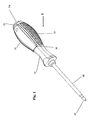
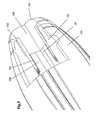
- FIGS. 1 to 4 show various representations of a first embodiment of a screwdriver 1.
- This has a handle 10 on which a shaft 40 is arranged.
- the handle 10 has, as in particular in FIG. 2 illustrated, a handle core 20, which is surrounded by a handle shell 30.
- the handle core 20 has a first end 20a and a second end 20b, wherein at the first end 20a of the shaft 40 is arranged.
- the longitudinal axis of the shaft 40 substantially coincides with the longitudinal axis of the handle core 20.
- the handle core 20 may be integrally connected to the shaft 40.
- the shaft 40 can also be interchangeably arranged on the handle core 20.
- the remote from the handle 10 end of the shaft 40 has an output 45, which can be configured in a known manner.
- a flat-blade screwdriver, a Phillips screwdriver or the like can be arranged on the shaft 40 as drive 45.
- the grip shell 30 has a first region 31, a second region 32 and a third region 33 in the longitudinal direction of the handle 10.
- the first region 31 lies in the region of the first end 20a of the handle core 20 and thus forms the end of the handle 10 facing the shaft 40.
- the third region 33 thus substantially adjoins the second end 20b of the handle core 20 and forms the front end of the handle Handle 10, which faces the user.
- the first region 31 is formed as a semi-soft zone. This first region 31 has a hardness of 60 to 80 Shore A.
- the first region 31 is produced on a thermoplastic elastomer, in particular of styrene-ethylene-butylene-styrene (SEBS), and can for example be sprayed directly onto the handle core 20.
- SEBS styrene-ethylene-butylene-styrene
- the first region 31 has an outer surface which widens symmetrically in the direction of the shaft 40. As a result, a slip protection is achieved, which prevents the fingers of the user's hand from slipping in the direction of the shaft 40 when the screwdriver 1 is used.
- the first region 31 is adjoined by the second region 32, which is formed as a soft zone with a hardness of 10 to 60 Shore A.
- the second region 32 is in particular made of a foamed material of the desired hardness, for example of a polyurethane foam.
- the foamed material can also be applied directly to the handle core 20.
- the second region 32 has a base body 32a, which is essentially hollow-cylindrical and can be pushed onto the grip core 20.
- a sheath 32b of the desired material is foamed.
- the foamed material fits particularly well to the palm of a user. In particular, it is possible to deform the foamed material by pressure accordingly, resulting in an ideal fit.
- the second region 32 has an outer surface, which is arched outwards and thus forms a particularly ergonomic handle shape.
- the handle core 20 may have longitudinal ribs 35 in the region in which the second region 32 is arranged, which engage in the base body 32a and thus form an anti-twist device.
- the second region 32 is adjoined by the third region 33, which is formed by a cap 33b.
- the cap 33b thus forms the end facing the user of the handle 10, wherein a part of the outer surface of the cap 33b thus forms an end face 33a.
- the cap 33b is formed as a hard zone with a hardness of more than 90 Shore A.
- the cap 33b is made in particular of a hard plastic such as polypropylene or cellulose acetate or steel.
- the second end 20 b of the handle core 20 has a toothing 20 c, which engages in a toothing 33 c of the cap 33 b, so that the cap 33 b is securely fixed to the handle core 20.
- the attachment of the cap 33b to the handle core 20 can also be done via other fastening means such as a locking mechanism, a thread or the like.
- FIG. 5 shows an alternative embodiment of a cap 33b ', which of the outer dimensions substantially of the cap 33b according to the in FIG. 4 illustrated embodiment corresponds.
- the cap 33b ' is not made entirely of a material, but has a steel insert 33d which forms the attachment to the handle core 20.
- the end 33a forming part of the cap 33b ' may be made for example of a hard plastic such as polypropylene or cellulose acetate.
- a viewing window can be recessed, behind which a symbol is arranged, which corresponds to the output 45 of the shaft 40. This makes it possible to see directly when using what type of screwdriver 1 it is.
- the first region 31 is preferably fixedly connected to the handle core 20.
- the second region 32 and the third region 33 can be interchangeably arranged on the handle core 20. This makes it possible to adapt the screwdriver 10 to different requirements. It is also possible for the handle 10 of the screwdriver 1 to be composed in a modular manner of the first region 31, the second region 32 and the third region 33, but then no longer allow replacement of the regions 31, 32, 33.
Landscapes
- Engineering & Computer Science (AREA)
- Mechanical Engineering (AREA)
- Details Of Spanners, Wrenches, And Screw Drivers And Accessories (AREA)
- Percussive Tools And Related Accessories (AREA)
- Passenger Equipment (AREA)
Description
- Die Erfindung betrifft einen Handgriff für ein Werkzeug, insbesondere für einen Schraubendreher gemäß dem Oberbegriff des Patentanspruchs 1.
- Bekannt sind Handgriffe für Werkzeuge, insbesondere für Schraubendreher, welche einen Griffkern aufweisen, auf welchem ein Griffmantel angeordnet ist. Der Griffkern ist an einem ersten Ende mit einem Schaft eines Schraubendrehers verbindbar oder verbunden. Die Griffmäntel der Handgriffe für Schraubendreher sind in verschiedenen Variationen bekannt. Insbesondere ist es bekannt, den Griffmantel aus einem Weichkunststoff herzustellen, damit der Handgriff besser in der Hand liegt.
- Beispielsweise ist der
DE 10 2005 037 504 B3 ein Handgriff für einen Schraubendreher zu entnehmen, bei welchem in einem Griffmantel aus einem Weichkunststoff Kammern vorgesehen sind, die sich in Längsrichtung des Handgriffs erstrecken, um eine besonders gute Anpassung des Handgriffs an die Hand eines Benutzers zu erreichen. - Der Erfindung liegt die Aufgabe zugrunde, einen Handgriff für ein Werkzeug, insbesondere für einen Schraubendreher bereitzustellen, welcher sich besser an die Hand eines Benutzers anpasst und insbesondere auch für Dauerbenutzung geeignet ist, ohne dass Druck- oder Reibstellen oder gar Blasen im Bereich der Handfläche des Benutzers entstehen.
- Die Aufgabe wird erfindungsgemäß gelöst durch einen Handgriff mit den Merkmalen des Patentanspruchs 1.
- Vorteilhafte Ausgestaltungen und Weiterbildungen der Erfindung sind in den Unteransprüchen angegeben.
- Der erfindungsgemäße Handgriff für ein Werkzeug, insbesondere für einen Schraubendreher weist einen Griffmantel auf, welcher in Längsrichtung in drei Bereiche unterteilbar ist. Die Längsrichtung wird dabei durch die Längsachse des Schafts des Schraubendrehers definiert. Ein erster Bereich des Griffmantels ist als semi-weiche Zone mit einer Härte von 60 bis 80 Shore A ausgebildet. An den ersten Bereich schließt sich ein zweiter Bereich an, welcher als weiche Zone mit einer Härte von 10 bis 60 Shore A ausgebildet ist. An den zweiten Bereich grenzt ein dritter Bereich an, welcher als harte Zone mit einer Härte von mehr als 90 Shore A ausgebildet ist. Der erste Bereich ist dabei dem Schaft des Werkzeugs, insbesondere des Schraubendrehers, zugewandt bzw. grenzt an das erste Endes Griffkerns an. Dadurch bildet der dritte Bereich den dem Benutzer zugewandten Abschluss des Werkzeugs bzw. des Schraubendrehers und bietet durch die Ausbildung als harte Zone die Möglichkeit, unter Umständen auch hohen Druck, beispielsweise durch Schläge mit einem Hammer, aufzunehmen und weiterzuleiten. Der zweite Bereich, welcher als weiche Zone ausgebildet ist, liegt in der Handfläche des Benutzers und schmiegt sich somit besonders gut an die Handfläche an. In dem ersten Bereich des Griffmantels kommen insbesondere der Daumen und der Zeigefinger der Hand des Benutzers zu liegen. Daher ist diese Zone als semi-weiche Zone ausgebildet und bildet somit eine Zwirbelzone, so dass Drehmomente von der Hand des Benutzers besonders gut auf den Schraubendreher übertragen werden können. Dadurch, dass der erste Bereich als leicht nachgebender Bereich ausgebildet ist, wird jedoch auch bei Dauerbenutzung die Hand des Benutzers geschont.
- Bei einer vorteilhaften Weiterbildung der Erfindung ist der erste Bereich aus einem thermoplastischen Elastomer, insbesondere aus Styrol-Ethylen-Butylen-Styrol (SEBS) gefertigt. Dieses Material in der gewünschten Härte bietet dem Benutzer besonderen Komfort und lässt sich zudem besonders kostengünstig verarbeiten.
- Bei einer besonders vorteilhaften Ausgestaltung der Erfindung ist der zweite Bereich aus einem thermoplastischen Elastomer oder einem geschäumten Material, insbesondere aus Polyurethan-Schaum, gefertigt. Ein geschäumtes Material hat gegenüber gespritztem Material den Vorteil, dass bei Belastung beispielsweise durch Druck der Handfläche das Volumen des Materials verändert werden kann und sich somit eine besonders günstige Anpassung des Materials an die Handfläche ergibt.
- Vorzugsweise ist der dritte Bereich aus Kunststoff gefertigt. Dadurch erhält dieser Bereich die gewünschte Härte und lässt sich zudem besonders einfach und kostengünstig fertigen.
- Bei einer vorteilhaften Weiterbildung weist der dritte Bereich einen Einsatz aus Stahl auf, sofern er nicht vollständig aus Stahl gefertigt ist. Dadurch erhält auch ein dritter Bereich, der ansonsten aus einem Hartkunststoff gefertigt ist, eine höhere Stabilität. Durch den Stahleinsatz können insbesondere höhere Impulse auf den Schaft übertragen werden.
- In einer vorteilhaften Ausgestaltung der Erfindung weist der erste Bereich eine Außenfläche auf, welche sich in Richtung auf den Schaft symmetrisch aufweitet. Dadurch wird eine Abrutschzone gebildet, welche verhindert, dass die Finger der Hand des Benutzers bei Ausüben von Druck zum Anziehen einer Schraube in Richtung auf den Schaft abrutschen.
Bei einer besonders bevorzugten Ausführungsform der Erfindung ist weist der zweite Bereich einer Außenfläche auf, welche symmetrisch nach außen gewölbt ist. Dadurch wird eine besonders ergonomische Griffform erreicht. - In einer Ausführungsform der Erfindung können die drei Bereiche direkt und unlösbar an dem Griffkern angeordnet sein. In einer alternativen bevorzugten Ausführungsform ist jedoch zumindest einer der Bereich auswechselbar, so dass der Handgriff einfach an verschiedene Anforderungen angepasst werden kann.
- Der Schaft kann in einer Ausführungsform einstückig an dem Griffkern angeordnet sein. Alternativ ist der Schaft jedoch auswechselbar an dem Griffkern angeordnet, um eine größere Flexibilität des Handgriffs zu ermöglichen.
- Vorzugsweise ist in der Stirnseite des dritten Bereichs ein Symbol für den Abtrieb angeordnet, so dass auf einfache Art und Weise erkannt werden kann, welche Art von Schraubendreher vorliegt. Vorzugsweise ist dieses Symbol hinter einem Sichtfenster angeordnet, durch welches insbesondere eine glatte Außenfläche des Handgriffs erreicht wird.
- Die Erfindung wird anhand der folgenden Figuren ausführlich erläutert. Es zeigt
- Fig. 1
- eine perspektivische Ansicht eines Schraubendrehers gemäß der Erfindung,
- Fig. 2
- eine Explosionsdarstellung des Schraubendrehers gemäß
Figur 1 , - Fig. 3
- eine teilweise Explosionsdarstellung des Schraubendrehers gemäß
Figur 1 , - Fig. 4
- eine vergrößerte dreidimensionale Darstellung eines Teilbereichs des Handgriffs des Schraubendrehers gemäß
Figur 1 mit teilweise geschnittener Ansicht und - Fig. 5
- eine perspektivische Darstellung eines Teilbereichs eines Handgriffs eines Schraubendrehers gemäß einer zweiten Ausführungsform der Erfindung mit teilweise geschnittener Ansicht.
- Die
Figuren 1 bis 4 zeigen verschiedene Darstellungen einer ersten Ausführungsform eines Schraubendrehers 1. Dieser weist einen Handgriff 10 auf, an welchem ein Schaft 40 angeordnet ist. Der Handgriff 10 weist, wie insbesondere inFigur 2 dargestellt, einen Griffkern 20 auf, welcher von einem Griffmantel 30 umgeben ist. Der Griffkern 20 weist ein erstes Ende 20a und ein zweites Ende 20b auf, wobei an dem ersten Ende 20a der Schaft 40 angeordnet ist. Die Längsachse des Schafts 40 stimmt im Wesentlichen mit der Längsachse des Griffkerns 20 überein. Der Griffkern 20 kann einstückig mit dem Schaft 40 verbunden sein. Alternativ kann der Schaft 40 auch auswechselbar an dem Griffkern 20 angeordnet werden. - Das von dem Handgriff 10 abgewandte Ende des Schafts 40 weist einen Abtrieb 45 auf, der in bekannter Art und Weise ausgestaltet sein kann. Beispielsweise kann an dem Schaft 40 als Antrieb 45 ein Schlitzschraubendreher, ein Kreuzschlitzschraubendreher oder Ähnliches angeordnet sein.
- Der Griffmantel 30 weist in Längsrichtung des Handgriffs 10 einen ersten Bereich 31, einen zweiten Bereich 32 und einen dritten Bereich 33 auf. Der erste Bereich 31 liegt im Bereich des ersten Endes 20a des Griffkerns 20 und bildet somit das dem Schaft 40 zugewandte Ende des Handgriffs 10. Der dritte Bereich 33 grenzt somit im Wesentlichen an das zweite Ende 20b des Griffkerns 20 an und bildet das stirnseitige Ende des Handgriffs 10, welches dem Benutzer zugewandt ist.
- Der erste Bereich 31 ist als semi-weiche Zone ausgebildet. Dieser erste Bereich 31 weist eine Härte von 60 bis 80 Shore A auf. Der erste Bereich 31 wird auf einem thermoplastischen Elastomer, insbesondere aus Styrol-Ethylen-Butylen-Styrol (SEBS) gefertigt und kann beispielsweise direkt auf den Griffkern 20 aufgespritzt werden.
- Der erste Bereich 31 weist eine Außenfläche auf, welche sich in Richtung auf den Schaft 40 symmetrisch aufweitet. Dadurch wird ein Abrutschschutz erreicht, welcher verhindert, dass bei Verwendung des Schraubendrehers 1 die Finger der Hand des Benutzers in Richtung auf den Schaft 40 abrutschen.
- An den ersten Bereich 31 schließt sich der zweite Bereich 32 an, welcher als weiche Zone mit einer Härte von 10 bis 60 Shore A ausgebildet ist. Dazu ist der zweite Bereich 32 insbesondere aus einem geschäumten Material der gewünschten Härte, beispielsweise aus einem Polyurethan-Schaum gefertigt. Das geschäumte Material kann ebenfalls direkt auf den Griffkern 20 aufgebracht werden. In dem vorliegenden Ausführungsbeispiel weist der zweite Bereich 32 jedoch einen Grundkörper 32a auf, welcher im Wesentlichen hohlzylindrisch ausgebildet ist und auf den Griffkern 20 aufgeschoben werden kann. Auf die Außenseite des Grundkörpers 32a wird eine Hülle 32b aus dem gewünschten Material aufgeschäumt. Das geschäumte Material legt sich besonders gut an die Handfläche eines Benutzers an. Insbesondere ist es möglich, das geschäumte Material durch Druck entsprechend zu verformen, wodurch sich eine ideale Passform ergibt.
- Der zweite Bereich 32 weist eine Außenfläche auf, welche nach außen gewölbt ist und somit eine besonders ergonomische Griffform bildet.
- Der Griffkern 20 kann in dem Bereich, in welchem der zweite Bereich 32 angeordnet ist, Längsrippen 35 aufweisen, welche in den Grundkörper 32a eingreifen und somit eine Verdrehsicherung bilden.
- An den zweiten Bereich 32 schließt sich der dritte Bereich 33 an, welcher durch eine Kappe 33b gebildet ist. Die Kappe 33b bildet somit das dem Benutzer zugewandte Ende des Handgriffs 10, wobei ein Teil der Außenfläche der Kappe 33b somit eine Stirnseite 33a bildet. Die Kappe 33b ist als harte Zone mit einer Härte von mehr als 90 Shore A ausgebildet. Dazu ist die Kappe 33b insbesondere aus einem Hartkunststoff wie beispielsweise Polypropylen oder Celluloseacetat oder aus Stahl gefertigt. Das zweite Ende 20b des Griffkerns 20 weist eine Verzahnung 20c auf, welche in eine Verzahnung 33c der Kappe 33b eingreift, so dass die Kappe 33b sicher an dem Griffkern 20 fixiert ist. Die Befestigung der Kappe 33b an dem Griffkern 20 kann auch über sonstige Befestigungsmittel wie beispielsweise ein Rastmechanismus, ein Gewinde oder Ähnliches erfolgen.
-
Figur 5 zeigt eine alternative Ausbildung einer Kappe 33b', welche von den Außenmaßen im Wesentlichen der Kappe 33b gemäß dem inFigur 4 dargestellten Ausführungsbeispiel entspricht. Die Kappe 33b' ist jedoch nicht vollständig aus einem Material gefertigt, sondern weist einen Stahleinsatz 33d auf, welcher die Befestigung zu dem Griffkern 20 hin bildet. Der die Stirnseite 33a bildende Teil der Kappe 33b' kann beispielsweise aus einem Hartkunststoff wie Polypropylen oder Celluloseacetat gefertigt sein. - In der Stirnseite 33a der Kappen 33b, 33b' kann in einer weiteren nicht dargestellten Ausführungsform ein Sichtfenster eingelassen sein, hinter welchem ein Symbol angeordnet ist, welches mit dem Abtrieb 45 des Schafts 40 korrespondiert. Dadurch ist bei der Benutzung direkt sichtbar, um welche Art von Schraubendreher 1 es sich handelt.
- Der erste Bereich 31 ist vorzugsweise fest mit dem Griffkern 20 verbunden. Der zweite Bereich 32 und der dritte Bereich 33 können auswechselbar an dem Griffkern 20 angeordnet werden. Dadurch wird es möglich, den Schraubendreher 10 an verschiedene Anforderungen anzupassen. Es ist auch möglich, den Handgriff 10 des Schraubendrehers 1 modulartig aus dem ersten Bereich 31, dem zweiten Bereich 32 und dem dritten Bereich 33 zusammenzusetzen, anschließend jedoch ein Auswechseln der Bereiche 31, 32, 33 nicht mehr zu ermöglichen.
-
- 1
- Schraubendreher
- 10
- Handgriff
- 20
- Griffkern
- 20a
- erstes Ende
- 20b
- zweites Ende
- 20c
- Verzahnung
- 25
- Rippen
- 30
- Griffmantel
- 31
- erster Bereich
- 32
- zweiter Bereich
- 32a
- Grundkörper
- 32b
- Hülle
- 33
- dritter Bereich
- 33a
- Stirnseite
- 33b
- Kappe
- 33b'
- Kappe
- 33c
- Verzahnung
- 33d
- Stahleinsatz
- 40
- Schaft
- 45
- Abtrieb
Claims (10)
- Handgriff (10) für ein Werkzeug, insbesondere für einen Schraubendreher (1), mit einem Griffkern (20), auf welchem ein Griffmantel (30) angeordnet ist, wobei der Griffkern (20) an einem ersten Ende (20a) mit einem Schaft (40) eines Werkzeugs, insbesondere eines Schraubendrehers (1), verbindbar oder verbunden ist,
dadurch gekennzeichnet, dass der Griffmantel (30) in Längsrichtung drei Bereiche (31, 32, 33) aufweist, wobei ein erster Bereich (31) als semiweiche Zone mit einer Härte von 60 bis 80 Shore A, ein an den ersten Bereich (31) angrenzender zweiter Bereich (32) als weiche Zone mit einer Härte von 10 bis 60 Shore A und ein an den zweiten Bereich (32) angrenzender dritter Bereich (33) als harte Zone mit einer Härte von mehr als 90 Shore A ausgebildet ist, wobei der erste Bereich (31) an das erste Ende (20a) des Griffkerns (20) angrenzt. - Handgriff nach Anspruch 1,
dadurch gekennzeichnet, dass der erste Bereich (31) aus einem thermoplastischen Elastomer, insbesondere aus Styrol-Ethylen-Butylen-Styrol, gefertigt ist. - Handgriff nach einem der vorhergehenden Ansprüche,
dadurch gekennzeichnet, dass der zweite Bereich (32) aus einem thermoplastischen Elastomer oder einem geschäumtem Material, insbesondere aus Polyurethan-Schaum, gefertigt ist. - Handgriff nach einem der vorhergehenden Ansprüche,
dadurch gekennzeichnet, dass der dritte Bereich (33) aus Kunststoff oder Stahl gefertigt ist. - Handgriff nach einem der vorhergehenden Ansprüche,
dadurch gekennzeichnet, dass der dritte Bereich (33) einen Einsatz aus Stahl (33d) aufweist. - Handgriff nach einem der vorhergehenden Ansprüche,
dadurch gekennzeichnet, dass der erste Bereich (31) eine Außenfläche aufweist, welche sich in Richtung auf den Schaft symmetrisch aufweitet. - Handgriff nach einem der vorhergehenden Ansprüche,
dadurch gekennzeichnet, dass der zweite Bereich (32) eine Außenfläche aufweist, welche nach außen gewölbt ist. - Handgriff nach einem der vorhergehenden Ansprüche,
dadurch gekennzeichnet, dass der erste Bereich (31) und/oder der zweite Bereich (32) und/oder der dritte Bereich (33) auswechselbar sind. - Handgriff nach einem der vorhergehenden Ansprüche,
dadurch gekennzeichnet, dass der Schaft (40) auswechselbar an dem Griffkern (20) angeordnet ist. - Handgriff nach einem der vorhergehenden Ansprüche,
dadurch gekennzeichnet, dass in der Stirnseite (33a) des dritten Bereichs (33) ein Symbol für den Abtrieb (45), vorzugsweise hinter einem Sichtfenster, angeordnet ist.
Applications Claiming Priority (1)
| Application Number | Priority Date | Filing Date | Title |
|---|---|---|---|
| DE102007022291A DE102007022291A1 (de) | 2007-05-12 | 2007-05-12 | Handgriff für ein Werkzeug, insbesondere für einen Schraubendreher |
Publications (3)
| Publication Number | Publication Date |
|---|---|
| EP1992454A2 EP1992454A2 (de) | 2008-11-19 |
| EP1992454A3 EP1992454A3 (de) | 2010-05-05 |
| EP1992454B1 true EP1992454B1 (de) | 2011-06-15 |
Family
ID=39677419
Family Applications (1)
| Application Number | Title | Priority Date | Filing Date |
|---|---|---|---|
| EP08007501A Ceased EP1992454B1 (de) | 2007-05-12 | 2008-04-17 | Handgriff für ein Werkzeug, insbesondere für einen Schraubendreher |
Country Status (4)
| Country | Link |
|---|---|
| US (1) | US20080276770A1 (de) |
| EP (1) | EP1992454B1 (de) |
| CN (1) | CN101301742A (de) |
| DE (1) | DE102007022291A1 (de) |
Cited By (1)
| Publication number | Priority date | Publication date | Assignee | Title |
|---|---|---|---|---|
| TWI499486B (zh) * | 2013-08-12 | 2015-09-11 | 起子工具結構 |
Families Citing this family (18)
| Publication number | Priority date | Publication date | Assignee | Title |
|---|---|---|---|---|
| EP2033849A1 (de) * | 2007-08-30 | 2009-03-11 | Peguform Gmbh | Kunststoffformteil zur Aufnahme einer Fahrzeugbatterie |
| DK177245B1 (da) * | 2008-06-27 | 2012-08-06 | Guldmann V As | Håndbetjening til hejsesystem |
| CN101992462B (zh) * | 2009-08-14 | 2015-08-19 | 杭州巨星科技股份有限公司 | 工具手柄及其制造方法 |
| US9931739B2 (en) | 2014-01-16 | 2018-04-03 | Milwaukee Electric Tool Corporation | Screwdriver |
| USD769689S1 (en) | 2015-01-15 | 2016-10-25 | Milwaukee Electric Tool Corporation | Fastener driver |
| US10071471B2 (en) * | 2015-08-17 | 2018-09-11 | Mayhew Steel Products, Inc. | Pry bar handle |
| US10195733B2 (en) * | 2015-08-17 | 2019-02-05 | Mayhew Steel Products, Inc. | Tool handle |
| US20170136618A1 (en) * | 2015-11-13 | 2017-05-18 | Ching-Ching Tsai | Handle for hand tool |
| TWI564123B (zh) * | 2016-08-03 | 2017-01-01 | 鴻安國際興業有限公司 | 膠槌 |
| US11253986B2 (en) * | 2016-11-30 | 2022-02-22 | Hangzhou Great Star Industrial Co., Ltd. | Handle and a hammering tool |
| US11059162B2 (en) | 2017-05-17 | 2021-07-13 | Milwaukee Electric Tool Corporation | Screwdriver |
| USD855433S1 (en) | 2017-08-09 | 2019-08-06 | Milwaukee Electric Tool Corporation | Screwdriver |
| US11110585B2 (en) * | 2017-11-02 | 2021-09-07 | Stanley Black & Decker, Inc. | Grip component for a hand tool |
| USD860750S1 (en) * | 2018-03-02 | 2019-09-24 | Wiha Werkzeuge Gmbh | Screwdriver handle |
| USD1031400S1 (en) | 2020-02-26 | 2024-06-18 | Hultafors Group Ab | Screwdriver |
| USD966068S1 (en) * | 2020-08-25 | 2022-10-11 | Hultafors Group Ab | Screwdriver |
| USD1101533S1 (en) | 2022-06-14 | 2025-11-11 | Wiha Werkzeuge Gmbh | Screwdriver |
| US12551997B2 (en) * | 2023-03-10 | 2026-02-17 | Black & Decker, Inc. | Hand tool having interchangeable grip |
Family Cites Families (17)
| Publication number | Priority date | Publication date | Assignee | Title |
|---|---|---|---|---|
| US3189069A (en) * | 1963-12-06 | 1965-06-15 | Stanley Works | Tool handle with resilient gripping means |
| US3481038A (en) * | 1967-11-13 | 1969-12-02 | John N Cooper | Knife construction |
| US3549189A (en) * | 1968-08-09 | 1970-12-22 | Michael Alosi | Tool handle |
| US4858504A (en) * | 1988-08-01 | 1989-08-22 | Jame Tsai | Screwdriver with insulated shaft and polygonal driving head |
| US4969231A (en) * | 1989-05-17 | 1990-11-13 | Easco Hand Tools, Inc. | Hand tool handle having end cap with indicia |
| US5390572A (en) * | 1993-07-27 | 1995-02-21 | Vermont American Corporation | Tool with immproved impact and torque capabilities and having ergonomic handle |
| DE4343650C2 (de) * | 1993-12-21 | 1996-04-11 | Hazet Werk Zerver Hermann | Griff für Handwerkzeuge |
| US5873148A (en) * | 1997-01-15 | 1999-02-23 | Hand Tool Design Corporation | Ergonomic handle system |
| US5956799A (en) * | 1997-09-10 | 1999-09-28 | Panaccione; Mark Thomas | Putty knife and scraper handle |
| DE29803967U1 (de) * | 1998-03-07 | 1998-04-23 | Felo-Werkzeugfabrik Holland-Letz GmbH, 35279 Neustadt | Werkzeug-Griff, insbesondere für Elektronik-Schraubendreher und ähnliche Geräte |
| US6295903B1 (en) * | 2000-03-22 | 2001-10-02 | The Stanley Works | Screwdriver and method for making same |
| FR2814104B1 (fr) * | 2000-09-20 | 2002-12-20 | Bost Garnache Ind | Manche de tournevis, procede de fabrication d'un tel manche, tournevis correspondant et gamme de tournevis constituee de tels tournevis |
| US7294110B2 (en) * | 2002-11-20 | 2007-11-13 | Boston Scientific Scimed Inc. | Medical instruments |
| DE202004019156U1 (de) * | 2004-12-10 | 2005-02-10 | Berner Gmbh | Griff für Werkzeuge |
| DE102005037504B3 (de) | 2004-12-23 | 2006-08-24 | Felo-Werkzeugfabrik Holland-Letz Gmbh | Verwendung eines Handgriffes für einen Schraubendreher |
| US7152511B2 (en) * | 2005-05-17 | 2006-12-26 | Shy Fen Fen | Polychrome transparent tool handle |
| US20070143942A1 (en) * | 2005-12-23 | 2007-06-28 | Polyworks, Inc. | Handle with soft gel cushioning member |
-
2007
- 2007-05-12 DE DE102007022291A patent/DE102007022291A1/de not_active Withdrawn
-
2008
- 2008-04-17 EP EP08007501A patent/EP1992454B1/de not_active Ceased
- 2008-05-08 US US12/151,707 patent/US20080276770A1/en not_active Abandoned
- 2008-05-12 CN CNA200810097084XA patent/CN101301742A/zh active Pending
Cited By (1)
| Publication number | Priority date | Publication date | Assignee | Title |
|---|---|---|---|---|
| TWI499486B (zh) * | 2013-08-12 | 2015-09-11 | 起子工具結構 |
Also Published As
| Publication number | Publication date |
|---|---|
| CN101301742A (zh) | 2008-11-12 |
| DE102007022291A1 (de) | 2008-11-13 |
| US20080276770A1 (en) | 2008-11-13 |
| EP1992454A3 (de) | 2010-05-05 |
| EP1992454A2 (de) | 2008-11-19 |
Similar Documents
| Publication | Publication Date | Title |
|---|---|---|
| EP1992454A2 (de) | Handgriff für ein Werkzeug, insbesondere für einen Schraubendreher | |
| DE69033751T2 (de) | Schlüsselloses Futter | |
| DE102016202831A1 (de) | Handwerkzeugmaschine | |
| DE3416964C2 (de) | Spannfutter für ein Werkzeug, insbes. zum Schlagbohren | |
| EP2756928B1 (de) | Handwerkzeugmaschine mit einem ergonomischen Handgriff | |
| EP0941814A2 (de) | Werkzeughandgriff | |
| DE9112630U1 (de) | Zangen-Handgriff | |
| WO2009089961A1 (de) | Handgriff für ein elektrohandwerkzeug | |
| DE102005055981B4 (de) | Handgriff für Werkzeuge und Betätigungselemente | |
| DE10063445B4 (de) | Betätigungshandgriff | |
| DE2800796A1 (de) | Handwerkzeug | |
| DE10252747A1 (de) | Aufbewahrungsvorrichtung für Schraubendrehereinsätze oder dergleichen | |
| DE102016012268B4 (de) | Werkzeugheft | |
| DE102010037372A1 (de) | Schlagschrauber mit außer Wirkung bringbarem Schlagrichtungswandler | |
| WO2009071376A1 (de) | Handgriff | |
| DE102005019140A1 (de) | Maschinenhandgriff | |
| DE19511092A1 (de) | Daumenring für endoskopische Geräte | |
| DE19901752C2 (de) | Meißel für Steinmetzarbeiten | |
| DE202023101127U1 (de) | Manuell ergreifbares und umgreifbares Griffteil für ein chirurgisches Instrument und ein chirurgisches Instrument | |
| DE8531992U1 (de) | Griffteil eines Handwerkzeugs für Ärzte, insbesondere Zahnärzte | |
| DE202015102812U1 (de) | Schraubendrehergriff | |
| DE102022124152A1 (de) | Handwerkzeug zum Öffnen von Folienverpackungen | |
| DE202004000140U1 (de) | Griffsatz für ein Hand- und Gartenwerkzeug | |
| EP0952902A1 (de) | Drehwerkzeug-system | |
| DE10107071A1 (de) | Griff zur Übertragung von Drehbewegungen im Umfassungsgriff |
Legal Events
| Date | Code | Title | Description |
|---|---|---|---|
| PUAI | Public reference made under article 153(3) epc to a published international application that has entered the european phase |
Free format text: ORIGINAL CODE: 0009012 |
|
| AK | Designated contracting states |
Kind code of ref document: A2 Designated state(s): AT BE BG CH CY CZ DE DK EE ES FI FR GB GR HR HU IE IS IT LI LT LU LV MC MT NL NO PL PT RO SE SI SK TR |
|
| AX | Request for extension of the european patent |
Extension state: AL BA MK RS |
|
| PUAL | Search report despatched |
Free format text: ORIGINAL CODE: 0009013 |
|
| AK | Designated contracting states |
Kind code of ref document: A3 Designated state(s): AT BE BG CH CY CZ DE DK EE ES FI FR GB GR HR HU IE IS IT LI LT LU LV MC MT NL NO PL PT RO SE SI SK TR |
|
| AX | Request for extension of the european patent |
Extension state: AL BA MK RS |
|
| RIC1 | Information provided on ipc code assigned before grant |
Ipc: B25G 1/10 20060101ALI20100401BHEP Ipc: B25G 1/01 20060101AFI20080829BHEP Ipc: B25B 23/16 20060101ALI20100401BHEP |
|
| 17P | Request for examination filed |
Effective date: 20100811 |
|
| GRAP | Despatch of communication of intention to grant a patent |
Free format text: ORIGINAL CODE: EPIDOSNIGR1 |
|
| RIC1 | Information provided on ipc code assigned before grant |
Ipc: B25B 23/16 20060101ALI20100923BHEP Ipc: B25G 1/10 20060101ALI20100923BHEP Ipc: B25G 1/01 20060101AFI20100923BHEP |
|
| AKX | Designation fees paid |
Designated state(s): DE |
|
| GRAS | Grant fee paid |
Free format text: ORIGINAL CODE: EPIDOSNIGR3 |
|
| GRAA | (expected) grant |
Free format text: ORIGINAL CODE: 0009210 |
|
| AK | Designated contracting states |
Kind code of ref document: B1 Designated state(s): DE |
|
| REG | Reference to a national code |
Ref country code: DE Ref legal event code: R096 Ref document number: 502008003830 Country of ref document: DE Effective date: 20110728 |
|
| PLBE | No opposition filed within time limit |
Free format text: ORIGINAL CODE: 0009261 |
|
| STAA | Information on the status of an ep patent application or granted ep patent |
Free format text: STATUS: NO OPPOSITION FILED WITHIN TIME LIMIT |
|
| 26N | No opposition filed |
Effective date: 20120316 |
|
| REG | Reference to a national code |
Ref country code: DE Ref legal event code: R097 Ref document number: 502008003830 Country of ref document: DE Effective date: 20120316 |
|
| PGFP | Annual fee paid to national office [announced via postgrant information from national office to epo] |
Ref country code: DE Payment date: 20210525 Year of fee payment: 14 |
|
| REG | Reference to a national code |
Ref country code: DE Ref legal event code: R119 Ref document number: 502008003830 Country of ref document: DE |
|
| PG25 | Lapsed in a contracting state [announced via postgrant information from national office to epo] |
Ref country code: DE Free format text: LAPSE BECAUSE OF NON-PAYMENT OF DUE FEES Effective date: 20221103 |