EP1992003B1 - Dispositif de coupure en surintensité - Google Patents
Dispositif de coupure en surintensité Download PDFInfo
- Publication number
- EP1992003B1 EP1992003B1 EP06706014.5A EP06706014A EP1992003B1 EP 1992003 B1 EP1992003 B1 EP 1992003B1 EP 06706014 A EP06706014 A EP 06706014A EP 1992003 B1 EP1992003 B1 EP 1992003B1
- Authority
- EP
- European Patent Office
- Prior art keywords
- current
- state
- contact system
- switching apparatus
- contact
- Prior art date
- Legal status (The legal status is an assumption and is not a legal conclusion. Google has not performed a legal analysis and makes no representation as to the accuracy of the status listed.)
- Not-in-force
Links
Images
Classifications
-
- H—ELECTRICITY
- H01—ELECTRIC ELEMENTS
- H01H—ELECTRIC SWITCHES; RELAYS; SELECTORS; EMERGENCY PROTECTIVE DEVICES
- H01H71/00—Details of the protective switches or relays covered by groups H01H73/00 - H01H83/00
- H01H71/10—Operating or release mechanisms
- H01H71/12—Automatic release mechanisms with or without manual release
- H01H71/42—Induction-motor, induced-current, or electrodynamic release mechanisms
- H01H71/43—Electrodynamic release mechanisms
-
- H—ELECTRICITY
- H01—ELECTRIC ELEMENTS
- H01H—ELECTRIC SWITCHES; RELAYS; SELECTORS; EMERGENCY PROTECTIVE DEVICES
- H01H79/00—Protective switches in which excess current causes the closing of contacts, e.g. for short-circuiting the apparatus to be protected
-
- H—ELECTRICITY
- H01—ELECTRIC ELEMENTS
- H01H—ELECTRIC SWITCHES; RELAYS; SELECTORS; EMERGENCY PROTECTIVE DEVICES
- H01H3/00—Mechanisms for operating contacts
- H01H3/22—Power arrangements internal to the switch for operating the driving mechanism
- H01H3/222—Power arrangements internal to the switch for operating the driving mechanism using electrodynamic repulsion
Landscapes
- Emergency Protection Circuit Devices (AREA)
- Breakers (AREA)
Claims (8)
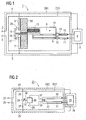
- Dispositif de coupure en surintensité pour des applications de moyenne tension ou de haute tension, comprenant des moyens ( 10, 11 ) de détection du courant pour le passage d'un système ( 20 ) de contact, qui leur est associé, lorsqu'un courant de seuil est dépassé, d'un premier état à un deuxième état, dans lequel, en aval des moyens ( 10, 11 ) de détection du courant, se trouvant dans une première branche de courant, sont montés, par des moyens ( 12, 13, 33, 34 ) d'accouplement, des moyens ( 14, 15, 18 ) d'actionnement, lesquels sont constitués pour le passage du premier au deuxième état du système ( 20 ) de contact se trouvant dans une deuxième branche de courant,
dans lequel
les moyens ( 10, 11 ) de détection du courant comprennent deux tronçons ( 10, 11 ) de barre de courant, qui s'étendent parallèlement l'un à l'autre, dans lesquels le courant passe en sens contraire et dont l'un ( 11 ), au moins, est déformable, le tronçon ( 11 ) déformable passant d'une position normale à une position de travail, lorsque le courant de seuil est dépassé. - Dispositif de coupure en surintensité suivant la revendication 1,
caractérisé en ce que
les moyens ( 12, 13 ) de couplage comprennent un élément ( 12 ) de blocage relié rigidement au tronçon ( 11 ) déformable. - Dispositif de coupure en surintensité suivant la revendication 2,
caractérisé en ce que
les moyens ( 14, 15, 18 ) d'actionnement comprennent un organe ( 14 ) d'actionnement, qui peut être soumis à l'action d'un ressort et qui a une constitution telle que, pour un élément ( 12 ) de blocage dans la position normal du tronçon ( 11 ) déformable, l'organe ( 14 ) d'actionnement est maintenu dans une position par le ressort ( 15 ) bandé et dans une position de travail du tronçon ( 11 ) déformable est libéré. - Dispositif de coupure en surintensité suivant la revendication 3,
caractérisé en ce que
l'organe ( 14 ) d'actionnement est un chariot ( 14 ) mobile, qui peut être soumis à l'action du ressort ( 15 ) et qui a une barre ( 18 ) de guidage reliée de manière rigide. - Dispositif de coupure en surintensité suivant l'une des revendications précédentes,
caractérisé en ce que
le système ( 20 ) de contact est formé d'un contact ( 19 ) mobile relié rigidement aux moyens ( 14, 15, 18 ) d'actionnement pour la constitution d'une liaison conductrice entre un premier contact ( 6 ) et un deuxième contre-contact ( 6, 7 ). - Dispositif de shuntage d'un module ( 1 ) électronique comprenant un dispositif de coupure en surintensité suivant l'une des revendications précédentes, les moyens ( 10, 11 ) de détection du courant étant constitués, pour le passage du système ( 20 ) de contact qui leur est associés, lorsqu'un courant de seuil est dépassé dans le module ( 1 ) électronique, d'un premier état, dans lequel le module électronique est raccordé à un montage à un deuxième état, dans lequel le module électronique est shunté dans le montage.
- Dispositif de shuntage suivant la revendication 6, caractérisé en ce que
le système ( 20 ) de contacts est relié d'une manière conductrice à des bornes ( 2, 3 ) de connexion du module ( 1 ) électronique. - Dispositif de shuntage suivant l'une des revendications 6 ou 7,
caractérisé en ce que
les moyens ( 10, 11 ) de connexion du courant détectent le courant du module ( 1 ) électronique.
Applications Claiming Priority (1)
| Application Number | Priority Date | Filing Date | Title |
|---|---|---|---|
| PCT/DE2006/000345 WO2007095874A1 (fr) | 2006-02-23 | 2006-02-23 | Dispositif de coupure en surintensité |
Publications (2)
| Publication Number | Publication Date |
|---|---|
| EP1992003A1 EP1992003A1 (fr) | 2008-11-19 |
| EP1992003B1 true EP1992003B1 (fr) | 2013-11-27 |
Family
ID=37031076
Family Applications (1)
| Application Number | Title | Priority Date | Filing Date |
|---|---|---|---|
| EP06706014.5A Not-in-force EP1992003B1 (fr) | 2006-02-23 | 2006-02-23 | Dispositif de coupure en surintensité |
Country Status (6)
| Country | Link |
|---|---|
| US (1) | US7936548B2 (fr) |
| EP (1) | EP1992003B1 (fr) |
| JP (1) | JP4942771B2 (fr) |
| CA (1) | CA2643129C (fr) |
| DE (1) | DE112006003862A5 (fr) |
| WO (1) | WO2007095874A1 (fr) |
Families Citing this family (2)
| Publication number | Priority date | Publication date | Assignee | Title |
|---|---|---|---|---|
| CN103635998B (zh) | 2011-06-21 | 2016-08-17 | Abb技术有限公司 | 具有接触机构的功率半导体壳体 |
| KR101846418B1 (ko) * | 2013-12-17 | 2018-04-06 | 지멘스 악티엔게젤샤프트 | Hvdc 컨버터를 위한 보호 전자 모듈 |
Citations (3)
| Publication number | Priority date | Publication date | Assignee | Title |
|---|---|---|---|---|
| DE1047915B (de) * | 1955-08-18 | 1958-12-31 | Siemens Ag | Hochspannungs-Schnellschalter mit Sperrmagnetausloesung, insbesondere UEberbrueckungsschalter zum Schutz von Reihenkondensatoren |
| DE10002870A1 (de) * | 2000-01-24 | 2001-08-23 | Abb Research Ltd | Vorrichtung zum Begrenzen eines Stromes |
| EP1526560A2 (fr) * | 2003-10-25 | 2005-04-27 | ABB PATENT GmbH | Disjoncteur électrique |
Family Cites Families (13)
| Publication number | Priority date | Publication date | Assignee | Title |
|---|---|---|---|---|
| US3215896A (en) * | 1962-10-04 | 1965-11-02 | Gen Electric | Fast response overload protection circuit |
| NO118930B (fr) * | 1965-04-20 | 1970-03-02 | Ericsson Telefon Ab L M | |
| DE2360037A1 (de) * | 1973-12-01 | 1975-06-12 | Danfoss As | Sicherheitsschaltung fuer ein elektrisches geraet |
| FR2426973A1 (fr) * | 1978-05-23 | 1979-12-21 | Laprom Corp Nv | Disjoncteur de courant de fuite |
| JPS59156347A (ja) * | 1983-02-26 | 1984-09-05 | オ−ジ−技研株式会社 | 部分浴治療装置 |
| JPS60130012A (ja) * | 1983-12-16 | 1985-07-11 | 株式会社リコー | 安全装置 |
| DE3544650A1 (de) * | 1984-12-20 | 1986-06-26 | General Electric Co., Schenectady, N.Y. | Hochgeschwindigkeits-kontakttreiber fuer einen elektrischen schalter |
| US4667071A (en) * | 1985-08-30 | 1987-05-19 | General Electric Company | Low voltage vacuum circuit interrupter |
| EP0303698A4 (fr) * | 1987-02-24 | 1990-03-27 | Vnii Pk I Avtomatizi | Interrupteur limiteur de courant. |
| FR2651915B1 (fr) * | 1989-09-13 | 1991-11-08 | Merlin Gerin | Disjoncteur statique ultra-rapide a isolement galvanique. |
| IT1303664B1 (it) * | 1998-12-24 | 2001-02-21 | Abb Ricerca Spa | Circuito elettronico di pilotaggio per attuatore bistabileattivato da piezoelettrici,particolarmente per dispositivi |
| JP3737372B2 (ja) * | 2001-02-26 | 2006-01-18 | 株式会社日立製作所 | 変流器入力型電源装置 |
| US6728085B2 (en) * | 2001-05-21 | 2004-04-27 | Eaton Corporation | Circuit breaker with shunt |
-
2006
- 2006-02-23 WO PCT/DE2006/000345 patent/WO2007095874A1/fr active Application Filing
- 2006-02-23 US US12/280,578 patent/US7936548B2/en not_active Expired - Fee Related
- 2006-02-23 DE DE112006003862T patent/DE112006003862A5/de not_active Withdrawn
- 2006-02-23 EP EP06706014.5A patent/EP1992003B1/fr not_active Not-in-force
- 2006-02-23 JP JP2008555603A patent/JP4942771B2/ja not_active Expired - Fee Related
- 2006-02-23 CA CA2643129A patent/CA2643129C/fr not_active Expired - Fee Related
Patent Citations (3)
| Publication number | Priority date | Publication date | Assignee | Title |
|---|---|---|---|---|
| DE1047915B (de) * | 1955-08-18 | 1958-12-31 | Siemens Ag | Hochspannungs-Schnellschalter mit Sperrmagnetausloesung, insbesondere UEberbrueckungsschalter zum Schutz von Reihenkondensatoren |
| DE10002870A1 (de) * | 2000-01-24 | 2001-08-23 | Abb Research Ltd | Vorrichtung zum Begrenzen eines Stromes |
| EP1526560A2 (fr) * | 2003-10-25 | 2005-04-27 | ABB PATENT GmbH | Disjoncteur électrique |
Also Published As
| Publication number | Publication date |
|---|---|
| WO2007095874A1 (fr) | 2007-08-30 |
| US7936548B2 (en) | 2011-05-03 |
| JP4942771B2 (ja) | 2012-05-30 |
| JP2009527878A (ja) | 2009-07-30 |
| DE112006003862A5 (de) | 2009-01-29 |
| CA2643129C (fr) | 2014-07-22 |
| EP1992003A1 (fr) | 2008-11-19 |
| US20090257165A1 (en) | 2009-10-15 |
| CA2643129A1 (fr) | 2007-08-30 |
Similar Documents
| Publication | Publication Date | Title |
|---|---|---|
| EP2044603B1 (fr) | Commutateur pour une installation de commutation d'alimentation et de distribution en énergie | |
| WO2007023113A1 (fr) | Corps isolant pour installation de distribution moyenne tension | |
| EP3241226B1 (fr) | Dispositif de court-circuit électrique | |
| EP1992003B1 (fr) | Dispositif de coupure en surintensité | |
| DE1929551A1 (de) | Hochspannungs-Trennschalter mit vorgeschalteten Widerstaenden | |
| EP2511956B1 (fr) | Protection contre les surtensions à trois commutateurs pour une installation photovoltaïque | |
| DE102022117625B3 (de) | Anordnung mit einem Gehäuse und einer elektrisch leitenden Kontaktfeder sowie Leistungshalbleitermodul hiermit | |
| EP3084794B1 (fr) | Dispositif de commutation | |
| EP2919246B1 (fr) | Module d'arbres de rotor pour un arbre de rotor d'un commutateur de puissance compact, arbre de rotor pour un commutateur de puissance compact, commutateur de puissance compact, ainsi que procédé de fabrication d'un module d'arbres de rotor pour un arbre de rotor d'un commutateur de puissance compact | |
| DE102014205915A1 (de) | Übertragungskinematik | |
| DE102006004401B3 (de) | Kontaktsystem für ein elektrisches Schaltgerät | |
| EP3011575B1 (fr) | Dispositif de transfert de forces | |
| DE102012201939A1 (de) | Schalteinheit für ein elektrisches Schaltgerät | |
| WO2021013763A1 (fr) | Appareil de commutation et dispositif de limitation de tension doté d'un appareil de commutation | |
| DE3743244A1 (de) | Schaltgeraeteanordnung zum zu- und abschalten von kondensatoren | |
| DE102020118308A1 (de) | Schalteinrichtung mit Betätigungseinheit, Bordnetz sowie Kraftfahrzeug | |
| EP3770935A1 (fr) | Dispositif de limitation de tension doté d'un appareil de commutation | |
| DE102012216974B4 (de) | Vorrichtung zur Übertragung von Kräften | |
| DE102012215528B4 (de) | Schalter, insbesondere Leistungsschalter für Niederspannungen | |
| DE102018109750A1 (de) | Schaltvorrichtung | |
| EP4018466B1 (fr) | Ensemble pour disjoncteur haute tension, et disjoncteur haute tension correspondant | |
| WO2008131703A1 (fr) | Module avec extension automatique d'un circuit de contrôle | |
| WO2008055693A1 (fr) | Installation de distribution électrique à haute tension | |
| WO2022223265A1 (fr) | Commutateur de sécurité rapide et système de commutateur de sécurité rapide | |
| DE102022122463A1 (de) | Gleichspannungsschaltgerät mit integriertem Unterbrechungsmechanismus |
Legal Events
| Date | Code | Title | Description |
|---|---|---|---|
| PUAI | Public reference made under article 153(3) epc to a published international application that has entered the european phase |
Free format text: ORIGINAL CODE: 0009012 |
|
| 17P | Request for examination filed |
Effective date: 20080731 |
|
| AK | Designated contracting states |
Kind code of ref document: A1 Designated state(s): CH DE FR GB LI SE |
|
| DAX | Request for extension of the european patent (deleted) | ||
| RBV | Designated contracting states (corrected) |
Designated state(s): CH DE FR GB LI SE |
|
| 17Q | First examination report despatched |
Effective date: 20101208 |
|
| RAP1 | Party data changed (applicant data changed or rights of an application transferred) |
Owner name: SIEMENS AKTIENGESELLSCHAFT |
|
| GRAP | Despatch of communication of intention to grant a patent |
Free format text: ORIGINAL CODE: EPIDOSNIGR1 |
|
| INTG | Intention to grant announced |
Effective date: 20130507 |
|
| GRAS | Grant fee paid |
Free format text: ORIGINAL CODE: EPIDOSNIGR3 |
|
| GRAA | (expected) grant |
Free format text: ORIGINAL CODE: 0009210 |
|
| AK | Designated contracting states |
Kind code of ref document: B1 Designated state(s): CH DE FR GB LI SE |
|
| REG | Reference to a national code |
Ref country code: GB Ref legal event code: FG4D Free format text: NOT ENGLISH |
|
| REG | Reference to a national code |
Ref country code: CH Ref legal event code: EP Ref country code: CH Ref legal event code: NV Representative=s name: SIEMENS SCHWEIZ AG, CH |
|
| REG | Reference to a national code |
Ref country code: DE Ref legal event code: R096 Ref document number: 502006013381 Country of ref document: DE Effective date: 20140123 |
|
| REG | Reference to a national code |
Ref country code: SE Ref legal event code: TRGR |
|
| RAP2 | Party data changed (patent owner data changed or rights of a patent transferred) |
Owner name: SIEMENS AKTIENGESELLSCHAFT |
|
| REG | Reference to a national code |
Ref country code: DE Ref legal event code: R097 Ref document number: 502006013381 Country of ref document: DE |
|
| PLBE | No opposition filed within time limit |
Free format text: ORIGINAL CODE: 0009261 |
|
| STAA | Information on the status of an ep patent application or granted ep patent |
Free format text: STATUS: NO OPPOSITION FILED WITHIN TIME LIMIT |
|
| 26N | No opposition filed |
Effective date: 20140828 |
|
| REG | Reference to a national code |
Ref country code: DE Ref legal event code: R097 Ref document number: 502006013381 Country of ref document: DE Effective date: 20140828 |
|
| REG | Reference to a national code |
Ref country code: FR Ref legal event code: PLFP Year of fee payment: 11 |
|
| REG | Reference to a national code |
Ref country code: FR Ref legal event code: PLFP Year of fee payment: 12 |
|
| REG | Reference to a national code |
Ref country code: CH Ref legal event code: PCOW Free format text: NEW ADDRESS: WERNER-VON-SIEMENS-STRASSE 1, 80333 MUENCHEN (DE) |
|
| REG | Reference to a national code |
Ref country code: FR Ref legal event code: PLFP Year of fee payment: 13 |
|
| PGFP | Annual fee paid to national office [announced via postgrant information from national office to epo] |
Ref country code: DE Payment date: 20180419 Year of fee payment: 13 |
|
| REG | Reference to a national code |
Ref country code: DE Ref legal event code: R119 Ref document number: 502006013381 Country of ref document: DE |
|
| PG25 | Lapsed in a contracting state [announced via postgrant information from national office to epo] |
Ref country code: DE Free format text: LAPSE BECAUSE OF NON-PAYMENT OF DUE FEES Effective date: 20190903 |
|
| PGFP | Annual fee paid to national office [announced via postgrant information from national office to epo] |
Ref country code: FR Payment date: 20210215 Year of fee payment: 16 |
|
| PGFP | Annual fee paid to national office [announced via postgrant information from national office to epo] |
Ref country code: GB Payment date: 20210302 Year of fee payment: 16 Ref country code: SE Payment date: 20210208 Year of fee payment: 16 |
|
| PGFP | Annual fee paid to national office [announced via postgrant information from national office to epo] |
Ref country code: CH Payment date: 20210504 Year of fee payment: 16 |
|
| REG | Reference to a national code |
Ref country code: SE Ref legal event code: EUG |
|
| REG | Reference to a national code |
Ref country code: CH Ref legal event code: PL |
|
| GBPC | Gb: european patent ceased through non-payment of renewal fee |
Effective date: 20220223 |
|
| PG25 | Lapsed in a contracting state [announced via postgrant information from national office to epo] |
Ref country code: SE Free format text: LAPSE BECAUSE OF NON-PAYMENT OF DUE FEES Effective date: 20220224 |
|
| PG25 | Lapsed in a contracting state [announced via postgrant information from national office to epo] |
Ref country code: FR Free format text: LAPSE BECAUSE OF NON-PAYMENT OF DUE FEES Effective date: 20220228 |
|
| PG25 | Lapsed in a contracting state [announced via postgrant information from national office to epo] |
Ref country code: LI Free format text: LAPSE BECAUSE OF NON-PAYMENT OF DUE FEES Effective date: 20220228 Ref country code: GB Free format text: LAPSE BECAUSE OF NON-PAYMENT OF DUE FEES Effective date: 20220223 Ref country code: CH Free format text: LAPSE BECAUSE OF NON-PAYMENT OF DUE FEES Effective date: 20220228 |