EP1991814B1 - Apparatus for distributing and controlling a heat carrier which originates from a heat and/or cold source - Google Patents
Apparatus for distributing and controlling a heat carrier which originates from a heat and/or cold source Download PDFInfo
- Publication number
- EP1991814B1 EP1991814B1 EP07722974.8A EP07722974A EP1991814B1 EP 1991814 B1 EP1991814 B1 EP 1991814B1 EP 07722974 A EP07722974 A EP 07722974A EP 1991814 B1 EP1991814 B1 EP 1991814B1
- Authority
- EP
- European Patent Office
- Prior art keywords
- heating
- return
- supply
- space
- pumps
- Prior art date
- Legal status (The legal status is an assumption and is not a legal conclusion. Google has not performed a legal analysis and makes no representation as to the accuracy of the status listed.)
- Active
Links
- 238000010438 heat treatment Methods 0.000 claims description 39
- 238000001816 cooling Methods 0.000 claims description 33
- 238000002156 mixing Methods 0.000 claims description 19
- 230000001105 regulatory effect Effects 0.000 claims description 12
- 238000001514 detection method Methods 0.000 claims description 3
- 239000000498 cooling water Substances 0.000 claims description 2
- 239000008236 heating water Substances 0.000 claims description 2
- 238000005192 partition Methods 0.000 claims description 2
- 238000009434 installation Methods 0.000 description 8
- 238000010276 construction Methods 0.000 description 4
- 238000004519 manufacturing process Methods 0.000 description 4
- 238000006243 chemical reaction Methods 0.000 description 2
- 230000001276 controlling effect Effects 0.000 description 1
- 230000007547 defect Effects 0.000 description 1
- 238000005265 energy consumption Methods 0.000 description 1
- 230000002349 favourable effect Effects 0.000 description 1
- 239000007788 liquid Substances 0.000 description 1
- 230000007257 malfunction Effects 0.000 description 1
- 239000000463 material Substances 0.000 description 1
- XLYOFNOQVPJJNP-UHFFFAOYSA-N water Substances O XLYOFNOQVPJJNP-UHFFFAOYSA-N 0.000 description 1
Images
Classifications
-
- F—MECHANICAL ENGINEERING; LIGHTING; HEATING; WEAPONS; BLASTING
- F24—HEATING; RANGES; VENTILATING
- F24D—DOMESTIC- OR SPACE-HEATING SYSTEMS, e.g. CENTRAL HEATING SYSTEMS; DOMESTIC HOT-WATER SUPPLY SYSTEMS; ELEMENTS OR COMPONENTS THEREFOR
- F24D3/00—Hot-water central heating systems
- F24D3/10—Feed-line arrangements, e.g. providing for heat-accumulator tanks, expansion tanks ; Hydraulic components of a central heating system
- F24D3/1058—Feed-line arrangements, e.g. providing for heat-accumulator tanks, expansion tanks ; Hydraulic components of a central heating system disposition of pipes and pipe connections
- F24D3/1066—Distributors for heating liquids
-
- F—MECHANICAL ENGINEERING; LIGHTING; HEATING; WEAPONS; BLASTING
- F24—HEATING; RANGES; VENTILATING
- F24D—DOMESTIC- OR SPACE-HEATING SYSTEMS, e.g. CENTRAL HEATING SYSTEMS; DOMESTIC HOT-WATER SUPPLY SYSTEMS; ELEMENTS OR COMPONENTS THEREFOR
- F24D3/00—Hot-water central heating systems
- F24D3/10—Feed-line arrangements, e.g. providing for heat-accumulator tanks, expansion tanks ; Hydraulic components of a central heating system
- F24D3/1091—Mixing cylinders
Definitions
- the invention relates to a device for distributing and controlling a coming from a heating and / or cooling source heat carrier in particular heating and / or cooling water, the heating and / or cooling bodies and / or surfaces is supplied in rooms of a building, with the features in that the device has an elongate housing which is separated in the longitudinal direction by a dividing wall into a longitudinally arranged feed space and into a return space arranged parallel thereto, that the flow of the heating and / or cooling source opens into the feed space from which the heats of the heating - and / or heat sink and / or surfaces branch off, that the returns of the heating and / or cooling body and / or surfaces open into the return space from which the return of the heating and / or cooling source emanates that in the Vor- and / or recirculation of the heating and / or cooling body and / or surfaces each a regulated decentralized pump is arranged.
- a distribution apparatus to which a plurality of circuits of a central heating system are connected.
- the device has an elongated housing whose interior has a flow chamber and a return chamber to which the headers and returns of the radiator and boiler are connected. Pumps are interposed in the supply and return lines of the radiators and boilers.
- the construction and connection of such a distribution device including the pump external to the device require a considerable amount of work.
- the DE 696 17 966 T2 discloses the preamble of independent claim 1.
- the object of the invention is to provide a device of the type mentioned, with low production and installation costs and with a small number of parts and small footprint for optimal supply of heating and / or Heatsink and / or surfaces of a building in particular an apartment or office provides.
- Such a compact manifold has all the essential parts such as: distribution pumps, central pump, especially mixing pump, check valves, sensors, controllers (master), switching power supply, an electronic assembly for multiple pumps, integrated motor controller possibly in an assembly (a board), filter, deaerator , modular design (function can be specified on site by simple conversion), expandable by simple addition of other distributors, little need for space.
- distribution pumps central pump, especially mixing pump, check valves, sensors, controllers (master), switching power supply
- an electronic assembly for multiple pumps possibly in an assembly (a board), filter, deaerator , modular design (function can be specified on site by simple conversion), expandable by simple addition of other distributors, little need for space.
- the installation effort is significantly reduced, the number of components small, mass production and the use of low-cost materials possible and the line losses are low in both the electrical and in the hydraulic lines.
- the compact, highly integrated design enables simple installation with low cable and wiring costs.
- a minimum water circulation is guaranteed and usually check valves are dispensable.
- the central pump can be regulated as required and a simple volume flow control over speed is possible.
- optimal accessibility for the service is given, especially if the device is located outside a home or office.
- a safe flow direction is achieved when check valves are arranged in the return runs of the heating and / or cooling bodies and / or surfaces.
- a check valve can also be arranged in the return of the heating and / or cooling source.
- An embodiment with a particularly favorable thermal control is created when the two rooms are connected to each other directly via a passage in particular as a mixing space for the admixture of cooler heat transfer medium from the return space in the flow chamber.
- a central or mixing pump is arranged, which promotes the originating from the flow of the heating and / or cooling source heat transfer, so that a very accurate control with low energy consumption is possible.
- the central or mixing pump convey the heat transfer medium into the mixing region between the return space and the supply space, in particular via an internal channel arranged in the device.
- a valve is arranged, with which the flow of the heating and / or cooling source can be regulated.
- a structurally particularly simple modular design is achieved when the device is divided into two or more sub-areas, each sub-area a flow space, a return space, connections for the supply and return lines to the heating and / or heat sink and / or surfaces and in particular having an internal channel to the mixing area.
- the device is modularly divided into two or more subregions, wherein at a portion of flow and return of the heating and / or cooling source is connected.
- Such a modular design allows for easy removal and conversion on site. If space is limited, additional distributors can be used.
- the device can be used as a distributor, as a hydraulic switch (s) and / or as an admixing pump (s).
- an electrical component with electrical connections and electronic components for regulating the pumps is arranged in or on the device.
- temperature and / or pressure sensors which are connected to the electrical component, can be arranged in and / or on the device.
- a device for distributing and regulating is provided for each housing or office unit. It is also of great advantage if the secondary circuits connected to the supply chamber are each connected to one, two or more heating and / or cooling bodies and / or surfaces of a room.
- At least one device for energy-specific heat quantity detection is arranged, so that additional devices, in particular thermostatic valves on the radiators, are not required for this purpose.
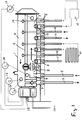
- Fig. 1 illustrated embodiment has an elongated housing 1, which is separated in the longitudinal direction by a partition wall 2 in a longitudinally arranged flow chamber (distribution chamber) 3 and in a return space 4 arranged parallel thereto. Both spaces 3, 4 may extend over the entire length of the housing 1.
- the flow chamber 3 is made shorter to provide space for a flow 5 and a return 6 a primary circuit in which a heat source, in particular a boiler and / or a cooling source.
- the flow 5 is connected via a plug connection 7 and a filter 8 arranged in a space 8 with the space 8, from which passes through a passage 10 of the incoming from the heating or cooling source heat carrier to the flow chamber 3.
- the passage 10 may also be arranged a valve.
- at least one breather may be arranged on the upper side of the housing.
- the supply lines go from 11, leading to radiators and / or heat sinks or heating and / or cooling surfaces H.
- the heat transfer medium in each case returns via return lines 12, which open into the return space 4.
- the feed lines 11 and the return lines 12 are in turn connected via connectors 7 to the device or the housing 1.
- a decentralized distributor pump 13 is arranged in each case, which sucks the heat transfer medium from the supply chamber 3 and conveys into the supply line.
- each leading to the heating and / or heat sink or surface H secondary circuit on a decentralized pump 13 so that thermostatic valves on the heat exchangers or the heating and / or cooling bodies or surfaces H are not required, but these decentralized Pumps bring the required due to their regulation Quantity of the heat carrier to the respective heating and / or cooling body or surface H.
- check valves 15 are arranged, which ensure that the heat carrier does not flow back into the return lines, but from the return space in the return line 6 of the primary circuit for heating or Cooling source passes.
- an electrical box 15 is fixed with electrical or electronic components and a power supply via electrical connections.
- the entire device is regulated with its individual parts, in particular the distributor pumps 13.
- a pressure and / or flow sensor 16 and three temperature sensors 17, 18 and 19 are arranged in the chamber 8 in the supply space 3 and in the return space 4.
- the distributor pumps 13 are controlled.
- further temperature sensors can be arranged in the secondary circuits.
- a pressure differential measuring device not shown, can be arranged between the flow 5 and the return 6, arranged.
- the medium or the heat transfer medium flows from the primary circuit 5, 6 in the flow chamber 8 of the manifold and from there via the passage 10 and a valve in the flow chamber 3. From there, the secondary circuits 11, 12 flows through the medium whose distributor pumps 13 are in operation. Thereafter, the medium enters the return chamber 4 and flows from there back into the primary circuit. Due to the check valves at the end of the return lines 12 backflow and thermal circulation are prevented.
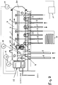
- the embodiment according to Fig. 2 is different from the after Fig. 1 essentially in that the supply space 3 are connected to the return space 4 with each other via a passage 20, which in the embodiment at one end of the interior of the device is arranged. Alternatively, this passage can also be provided elsewhere. Due to this connection of the two spaces, there is a partial mixing of the heat carrier or medium of both chambers 3, 4.
- This passage 20 is given an additional admixing function, due to a channel 21 opening into the passage area, which communicates with the flow 5 via the chamber 8 connected is.
- the heat transfer medium of the flow 5 of the primary circuit thus does not reach as in the embodiment Fig. 1 via the passage 10 in the flow chamber 3, but via the longitudinal channel 21 to the passage 20, which forms a mixing chamber there. This ensures that only as much heated or cooled liquid enters the supply lines 11, as is required in each case, that is, the decentralized distribution pumps 13 do not promote the medium of the supply line 5 unmixed in the supply lines 11, but in a mixed form.
- a central pump as mixing pump 22 which ensures how much medium or heat transfer medium passes through the channel 21 to the passage 20 and to the local mixing space.
- This pump 22 is in turn regulated by the electronics in the box 15, in particular using the arranged sensors.
- the medium flows from the supply chamber 8 through the secondary circuits into the return chamber 4 of the distributor.
- a flow through the primary circuit 5, 6 does not take place as long as the mixing pump 22 is turned off.
- After switching on the mixing pump 22 from the primary circuit to the secondary circuit only as much medium is supplied until, for example, a predetermined mixing temperature is reached. This is particularly interesting in combined systems such as radiators plus surface heating systems with different requirements regarding the flow temperature.
- a separate mixer can be omitted due to the mixing pump 22.
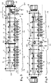
- the distributor device is in the embodiments according to 3 and 4 Modular modular design in which individual housing parts each form a manifold portion 1a with flow lines 11 and remindlaut effet 12, wherein two or more of these manifold areas are attached to each other.
- one distribution area is used per apartment, per office or per dwelling area or office area.
- a distributor region 1a is closed by a closure part 1b and at the other end a connection region 1c is connected as a separate housing, so that the flow chamber 8, the connection to the flow chamber 3 and the connection to the return chamber 4 forms and to the further flow and return 6 of the primary circuit are connected.
- connection region 1c needs to be fastened with its housing only to the housing of the distributor region 1a, in particular screwed on in order to obtain a complete distributor device.
- the supplied via the pump 22 longitudinal channel 21 is connected to the longitudinal channel 21 of the in Fig. 3 Connected left second distribution area 1a, so that the second distribution area is supplied via the pump 22.
- the box 15 is fastened to the electrical and electronic components.
- FIG. 4 an embodiment shown in which on both sides of the terminal portion 1c a respective distributor region 1a is connected, each with a separate electrical or electronic box 15 at the respective free end, in particular attached to the closure member 1b, so that the secondary circuits of the one distributor region 1a different can be regulated with respect to the secondary circuits of the other distribution area 1a.
- connection area 1c two pumps are shown.
- the upper pump 22 promotes as Beimischpumpe in the channel 21 with the above function and the underlying pump 26 promotes the flow 5 directly into the flow chamber 3, so that the connection area 1c as well as the embodiment according to Fig. 1 as well as alternatively as the execution after Fig. 2 can work.
- the housings of the distributor device and in particular also of the distributor regions and the connection regions, are elongated. Instead, these housings can also have other shapes and in particular box-shaped, cubic or be circular disk-shaped. This does not change the design features and functions described so far.
- measuring devices are arranged in particular sensors for energy in particular heat quantity detection, which has been used by the respective consumer.
- 13 sensors may also be provided in the secondary circuits and in particular in the distributor pumps.
Description
Die Erfindung betrifft eine Vorrichtung zum Verteilen und Regeln eines von einer Heiz- und/oder Kühlquelle stammenden Wärmeträgers insbesondere Heiz- und/oder Kühlwasser, das Heiz- und/oder Kühlkörpern und/oder -flächen in Räumen eines Gebäudes zugeführt wird, mit den Merkmalen, dass die Vorrichtung ein längliches Gehäuses aufweist, das in Längsrichtung durch eine Trennwand in einen längs angeordneten Vorlaufraum und in einen parallel dazu angeordneten Rücklaufraum getrennt ist, dass der Vorlauf der Heiz- und/oder Kühlquelle in den Vorlaufraum mündet von dem die Vorläufe der Heiz- und/oder Kühlkörper und/oder -flächen abzweigen, dass die Rückläufe der Heiz- und/oder Kühlkörper und/oder -flächen in den Rücklaufraum münden, von dem der Rücklauf der Heiz- und/oder Kühlquelle ausgeht, dass in den Vor- und/oder Rückläufen der Heiz- und/oder Kühlkörper und/oder -flächen jeweils eine geregelte dezentrale Pumpe angeordnet ist.The invention relates to a device for distributing and controlling a coming from a heating and / or cooling source heat carrier in particular heating and / or cooling water, the heating and / or cooling bodies and / or surfaces is supplied in rooms of a building, with the features in that the device has an elongate housing which is separated in the longitudinal direction by a dividing wall into a longitudinally arranged feed space and into a return space arranged parallel thereto, that the flow of the heating and / or cooling source opens into the feed space from which the heats of the heating - and / or heat sink and / or surfaces branch off, that the returns of the heating and / or cooling body and / or surfaces open into the return space from which the return of the heating and / or cooling source emanates that in the Vor- and / or recirculation of the heating and / or cooling body and / or surfaces each a regulated decentralized pump is arranged.
Um Räume eines Gebäudes insbesondere einer Wohnung zu wärmen oder zu kühlen sind aufwendige Installationen bekannt mit vielen einzelnen Komponenten wie Pumpen, Lüfter, Regelventile, Bypässe, Mischer, Rückschlagventile, Regelgeräten und vieles mehr. Dies führt zu einem erheblichen Herstellungs- und Installationsaufwand mit zahlreichen Leitungsverbindungen, die zudem die Anfälligkeit für Defekte und Fehlfunktionen erhöhen. Auch sind an jedem Heizkörper eines Raumes Thermostatventile befestigt, die den Herstellungs- und Installationsaufwand weiterhin erhöhen und Fehlbedienungen herausfordern. Ferner kommt es häufig zu unerwünschten gegenseitigen hydraulischen Beeinflussungen.In order to warm or cool rooms of a building, in particular an apartment complex installations are known with many individual components such as pumps, fans, control valves, bypasses, mixers, check valves, control devices and much more. This leads to a considerable manufacturing and installation effort with numerous cable connections, which also increase the susceptibility to defects and malfunction. Also are at each Radiator of a room attached to thermostatic valves, which continue to increase the production and installation costs and challenge operator error. Furthermore, there are often undesirable mutual hydraulic influences.
Aus der
Aus der
Diese Aufgabe wird erfindungsgemäß dadurch gelöst, dass die Pumpen innerhalb des Gehäuses der Vorrichtung angeordnet sind.This object is achieved in that the pumps are arranged within the housing of the device.
Ein solcher kompakter Verteiler weist alle wesentlichen Teile auf wie: Verteilpumpen, Zentralpumpe, insbesondere Beimischpumpe, Rückschlagventile, Sensoren, Regler (Master), Schaltnetzteil, eine Elektronikbaugruppe für mehrere Pumpen, integrierte Motorregler ggf. in einer Baugruppe (eine Platine), Filter, Entlüfter, modularer Aufbau (Funktion kann vor Ort durch einfachen Umbau festgelegt werden), erweiterbar durch einfachen Anbau weiterer Verteiler, geringer Platzbedarf. Der Installationsaufwand ist deutlich verringert, die Anzahl der Komponenten klein, eine Serienproduktion und der Einsatz kostengünstiger Materialien möglich und die Leitungsverluste sind sowohl in den elektrischen als auch in den hydraulischen Leitungen gering.Such a compact manifold has all the essential parts such as: distribution pumps, central pump, especially mixing pump, check valves, sensors, controllers (master), switching power supply, an electronic assembly for multiple pumps, integrated motor controller possibly in an assembly (a board), filter, deaerator , modular design (function can be specified on site by simple conversion), expandable by simple addition of other distributors, little need for space. The installation effort is significantly reduced, the number of components small, mass production and the use of low-cost materials possible and the line losses are low in both the electrical and in the hydraulic lines.
Durch die kompakte, hoch integrierte Bauweise ist eine einfache Installation bei geringem Leitungs- und Verdrahtungsaufwand möglich. Ein Mindestwasserumlauf ist gewährleistet und in der Regel sind Rückschlagventile entbehrlich. Die zentrale Pumpe kann bedarfsgerecht geregelt werden und es ist eine einfache Volumenstromregelung über Drehzahl möglich. Zudem ist eine optimale Zugänglichkeit für den Service gegeben, insbesondere dann, wenn die Vorrichtung außerhalb einer Wohnung bzw. eines Büros angeordnet ist.The compact, highly integrated design enables simple installation with low cable and wiring costs. A minimum water circulation is guaranteed and usually check valves are dispensable. The central pump can be regulated as required and a simple volume flow control over speed is possible. In addition, optimal accessibility for the service is given, especially if the device is located outside a home or office.
Besonders vorteilhafte Ausgestaltungen bezüglich der Pumpen insbesondere in Bezug auf die obengenannten Vorteile sind in den Ansprüchen 2 bis 8 aufgeführt.Particularly advantageous embodiments with regard to the pumps, in particular with regard to the abovementioned advantages, are listed in
Eine äußerst kompakte Bauweise wird erreicht, wenn Vorlaufraum und Rücklaufraum innerhalb desselben Gehäuses und/oder Körpers der Vorrichtung angeordnet sind.An extremely compact construction is achieved if the supply space and the return space are arranged within the same housing and / or body of the device.
Eine sichere Strömungsrichtung wird erreicht, wenn in den Rückläufen der Heiz- und/oder Kühlkörper und/oder -flächen Rückschlagventile angeordnet sind.A safe flow direction is achieved when check valves are arranged in the return runs of the heating and / or cooling bodies and / or surfaces.
Hierzu kann auch im Rücklauf der Heiz- und/oder Kühlquelle ein Rückschlagventil angeordnet sein.For this purpose, a check valve can also be arranged in the return of the heating and / or cooling source.
Eine Ausführung mit einer besonders günstigen wärmetechnischen Regelung wird geschaffen, wenn zur Beimischung von kühlerem Wärmeträger aus dem Rücklaufraum in den Vorlaufraum die beiden Räume miteinander direkt über einen Durchlass insbesondere als Mischraum verbunden sind. Hierzu ist es besonders vorteilhaft, wenn innerhalb der Vorrichtung eine Zentral- oder Beimischpumpe angeordnet ist, die den vom Vorlauf der Heiz- und/oder Kühlquelle stammenden Wärmeträger fördert, so dass eine sehr genaue Regelung bei geringem Energieaufwand möglich ist. Hierbei kann die Zentral- oder Beimischpumpe den Wärmeträger in den Mischbereich zwischen Rücklaufraum und Vorlaufraum insbesondere über einen in der Vorrichtung angeordneten internen Kanal fördern. Auch ist von Vorteil, wenn innerhalb der Vorrichtung ein Ventil angeordnet ist, mit dem der Vorlauf der Heiz- und/oder Kühlquelle regelbar ist.An embodiment with a particularly favorable thermal control is created when the two rooms are connected to each other directly via a passage in particular as a mixing space for the admixture of cooler heat transfer medium from the return space in the flow chamber. For this purpose, it is particularly advantageous if within the device, a central or mixing pump is arranged, which promotes the originating from the flow of the heating and / or cooling source heat transfer, so that a very accurate control with low energy consumption is possible. Here, the central or mixing pump convey the heat transfer medium into the mixing region between the return space and the supply space, in particular via an internal channel arranged in the device. It is also advantageous if, within the device, a valve is arranged, with which the flow of the heating and / or cooling source can be regulated.
Ein konstruktiv besonders einfacher modulweiser Aufbau wird erreicht, wenn die Vorrichtung baukastenförmig in zwei oder mehr Teilbereiche aufgeteilt ist, wobei jeder Teilbereich einen Vorlaufraum, einen Rücklaufraum, Anschlüsse für die Vor- und Rücklaufleitungen zu den Heiz- und/oder Kühlkörper und/oder -flächen und insbesondere einen internen Kanal zum Mischbereich aufweist.A structurally particularly simple modular design is achieved when the device is divided into two or more sub-areas, each sub-area a flow space, a return space, connections for the supply and return lines to the heating and / or heat sink and / or surfaces and in particular having an internal channel to the mixing area.
In einer weiteren Ausgestaltung wird vorgeschlagen, dass die Vorrichtung baukastenförmig in zwei oder mehr Teilbereiche aufgeteilt ist, wobei an einem Teilbereich Vor- und Rücklauf der Heiz- und/oder Kühlquelle angeschlossen ist. Ein solch modularer Aufbau ermöglicht vor Ort einen einfachen Ausbau als auch Umbau. Bei geringem Platzbedarf können weitere Verteiler angesetzt werden.In a further embodiment, it is proposed that the device is modularly divided into two or more subregions, wherein at a portion of flow and return of the heating and / or cooling source is connected. Such a modular design allows for easy removal and conversion on site. If space is limited, additional distributors can be used.
Dadurch ist die Vorrichtung einsetzbar als Verteiler, als hydraulische Weiche(n) und/oder als Beimischpumpe(n).As a result, the device can be used as a distributor, as a hydraulic switch (s) and / or as an admixing pump (s).
Vorzugsweise wird vorgeschlagen, dass in oder an der Vorrichtung ein elektrisches Bauteil mit elektrischen Anschlüssen und Elektronikteilen zur Regelung der Pumpen angeordnet ist. Hierbei kann in und/oder an der Vorrichtung Temperatur- und/oder Drucksensoren angeordnet sein, die mit dem elektrischen Bauteil verbunden sind.It is preferably proposed that an electrical component with electrical connections and electronic components for regulating the pumps is arranged in or on the device. In this case, temperature and / or pressure sensors, which are connected to the electrical component, can be arranged in and / or on the device.
Besonders vorteilhaft ist es, wenn für jede Wohnungs- oder Büroeinheit eine Vorrichtung zum Verteilen und Regeln vorgesehen ist. Auch ist es von größtem Vorteil, wenn die am Vorlaufraum angeschlossenen Sekundärkreise jeweils mit einem, zwei oder mehreren Heiz- und/oder Kühlkörpern und/oder-flächen eines Raumes verbunden sind.It is particularly advantageous if a device for distributing and regulating is provided for each housing or office unit. It is also of great advantage if the secondary circuits connected to the supply chamber are each connected to one, two or more heating and / or cooling bodies and / or surfaces of a room.
Eine einfache Montage als auch ein einfacher Austausch von Modulen und Teilen wird erreicht, wenn die Anschlüsse der den Wärmeträger führenden Leitungen lösbar insbesondere Steckverbindungen sind.A simple installation as well as a simple replacement of modules and parts is achieved if the connections of the heat carrier leading lines are releasably in particular connectors.
Besonders vorteilhaft ist es, wenn mindestens eine Einrichtung zur Energieinsbesondere Wärmemengenerfassung angeordnet ist, so dass hierfür zusätzliche Einrichtungen insbesondere Thermostatventile an den Heizkörpern nicht erforderlich sind.It is particularly advantageous if at least one device for energy-specific heat quantity detection is arranged, so that additional devices, in particular thermostatic valves on the radiators, are not required for this purpose.
Ausführungsbeispiele der Erfindung sind in den Zeichnungen in Längsschnitten schematisch dargestellt und werden im Folgenden näher beschrieben. Es zeigen
- Fig. 1
- die Vorrichtung mit von einander getrenntem Vorlauf- und Rücklaufraum ohne Unterstützungspumpe,
- Fig. 2
- eine zweite Ausführung mit verbundenem Vorlauf- und Rücklaufraum und mit einer Beimischfunktion über eine Beimischpumpe,
- Fig. 3
- einen modularen Aufbau mit hydraulischer Weiche und Beimischfunktion,
- Fig. 4
- einen modularen Aufbau mit doppelter Beimischfunktion und doppelter Anordnung elektrischer/elektronischer Bauteile.
- Fig. 1
- the device with separate flow and return space without support pump,
- Fig. 2
- a second embodiment with connected flow and return space and with an admixing function via an admixing pump,
- Fig. 3
- a modular design with hydraulic diverter and mixing function,
- Fig. 4
- a modular design with double blending function and double arrangement of electrical / electronic components.
Die in
Von dem Vorlaufraum 3 gehen die Vorlaufleitungen 11 ab, die zu Heizkörpern und/oder Kühlkörpern bzw. Heiz- und/oder Kühlflächen H führen. Nachdem der Wärmeträger diese durchflossen hat, gelangt der Wärmeträger jeweils wieder zurück über Rücklaufleitungen 12, die im Rücklaufraum 4 münden. Die Vorlaufleitungen 11 und die Rücklaufleitungen 12 sind wiederum über Steckverbindungen 7 mit der Vorrichtung bzw. dem Gehäuse 1 verbunden. Zu Beginn jeder Vorlaufleitung und im Ausführungsbeispiel auf der dem Vorlaufraum zugewandten Seite der Steckverbindung 7 ist jeweils eine dezentrale Verteilerpumpe 13 angeordnet, die den Wärmeträger aus dem Vorlaufraum 3 heraussaugt und in die Vorlaufleitung fördert. Damit weist jeder zum Heiz- und/oder Kühlkörper bzw. -fläche H führende Sekundärkreis eine dezentrale Pumpe 13 auf, so dass Thermostatventile an den Wärmetauschern bzw. den Heiz- und/oder Kühlkörpern bzw. -flächen H nicht erforderlich sind, sondern diese dezentralen Pumpen bringen aufgrund ihrer Regelung die erforderliche Menge des Wärmeträgers zu dem jeweiligen Heiz- und/oder Kühlkörper bzw. - fläche H.From the
In den Rücklaufleitungen 12, insbesondere an der Stelle, an der sie in den Rücklaufraum 4 münden, sind Rückschlagventile 15 angeordnet, die dafür sorgen, dass der Wärmeträger in die Rücklaufleitungen nicht zurückfließt, sondern vom Rücklaufraum in die Rücklaufleitung 6 des Primärkreises zur Heiz- bzw. Kühlquelle gelangt.In the return lines 12, in particular at the point where they open into the
Auf einer Seite insbesondere einer Stirnseite an einem Ende des Gehäuses 1 ist ein elektrischer Kasten 15 befestigt mit elektrischen oder elektronischen Bauteilen und einer Spannungsversorgung über elektrische Anschlüsse. Über die Einrichtung wird die gesamte Vorrichtung mit deren Einzelteile geregelt, insbesondere die Verteilerpumpen 13. Hierzu sind ein Druck- und/oder Strömungssensor 16 und drei Temperatursensoren 17, 18 und 19 in der Kammer 8 im Vorlaufraum 3 und im Rücklaufraum 4 angeordnet. Entsprechend der dort erfassten Werte werden die Verteilerpumpen 13 gesteuert. Hierbei können noch weitere Temperatursensoren in den Sekundärkreisen angeordnet sein. Auch kann zwischen dem Vorlauf 5 und dem Rücklauf 6 ein nicht dargestelltes Druckdifferenzmessgerät angeordnet sein.On one side, in particular a front side at one end of the housing 1, an
Bei der Inbetriebnahme einer oder mehrerer Verteilerpumpen 13 strömt das Medium bzw. der Wärmeträger aus dem Primärkreis 5, 6 in die Vorlaufkammer 8 des Verteilers und von dort über den Durchlass 10 bzw. ein Ventil in den Vorlaufraum 3. Von dort werden die Sekundärkreise 11, 12 von dem Medium durchströmt, deren Verteilerpumpen 13 in Betrieb sind. Danach gelangt das Medium in den Rücklaufraum 4 und strömt von dort wieder in den Primärkreis. Aufgrund der Rückschlagventile am Ende der Rücklaufleitungen 12 werden Rückströmungen und thermische Zirkulationen verhindert.When commissioning one or more distribution pumps 13, the medium or the heat transfer medium flows from the
Die Ausführungsform nach
An der Verbindungsstelle zwischen der Vorlaufkammer 8 und dem Längskanal 21 befindet sich eine Zentralpumpe als Beimischpumpe 22, die dafür sorgt, wie viel Medium bzw. Wärmeträger über den Kanal 21 zum Durchlauf 20 bzw. zu dem dortigen Mischraum gelangt. Diese Pumpe 22 ist wiederum über die Elektronik im Kasten 15 geregelt, insbesondere unter Nutzung der angeordneten Sensoren.At the junction between the
Bei der Inbetriebnahme einer oder mehrerer Verteilerpumpen 13 (hierbei können auch eine oder mehrere Verteilerpumpen 13 bis auf Null heruntergefahren sein), strömt das Medium aus der Vorlaufkammer 8 durch die Sekundärkreise in die Rücklaufkammer 4 des Verteilers. Eine Durchströmung des Primärkreises 5, 6 findet solange nicht statt, wie die Beimischpumpe 22 ausgeschaltet ist. Nach dem Einschalten der Beimischpumpe 22 wird aus dem Primärkreislauf dem Sekundärkreis nur so viel Medium zugeführt, bis zum Beispiel eine vorgegebene Mischtemperatur erreicht ist. Dies ist insbesondere auch dann interessant bei kombinierten Systemen wie Radiator plus Flächenheizungen mit unterschiedlichen Anforderungen bezüglich der Vorlauftemperatur. Ein separater Mischer kann aufgrund der Beimischpumpe 22 entfallen.When commissioning one or more distributor pumps 13 (in this case one or more distributor pumps 13 can also be shut down to zero), the medium flows from the
Die Verteilervorrichtung ist in den Ausführungen nach
Ein solcher modularer Aufbau führt zu einer hohen Flexibilität und Anpassungsfähigkeit. So ist in
Im Anschlussbereich 1c sind zwei Pumpen dargestellt. Die obere Pumpe 22 fördert als Beimischpumpe in den Kanal 21 mit der obengenannten Funktion und die darunter liegende Pumpe 26 fördert vom Vorlauf 5 direkt in den Vorlaufraum 3, so dass der Anschlussbereich 1c sowohl wie die Ausführung nach
Hierbei kann im Durchlassbereich 20 zwischen den Räumen 3 und 4 an der Stelle 27 ein Absperrteil angeordnet, das auch als Ventil arbeiten kann, so dass entweder die beiden Räume 3, 4 voneinander vollständig getrennt sind oder aber mehr oder weniger eine Verbindung miteinander besitzen. Auch dieses Absperrteil bzw. Ventil 27 ist wie alle anderen Ventile über die Elektronik im Kasten 15 regelbar. Erfindungsgemäss sind die dezentralen Pumpen 13 innerhalb des Gehäuses 1 der Vorrichtung angeordnet. Zusätzlich sind folgende Ausführungen möglich:
Die Pumpen Die dezentralen Pumpen 13 sind an der Verbindungsstelle der Vor- und/oder Rücklaufleitungen Die dezentralen Pumpen 13 sind zu Beginn der Vor- und/oder Rücklaufleitungen Die dezentralen Pumpen 13 sind im Bereich der Steckverbindung der Vor- und/oder Rücklaufleitungen oder den Räumen Die dezentralen Pumpen 13 sind auf der dem Vor- bzw.Rücklaufraum Die dezentralen Pumpen 13 sind im Vor- und/oder Rücklauf, insbesondere in den Vor- und/oder Rücklaufleitungen Die dezentralen Pumpen 13 sind an oder innerhalb der Gehäusewand angeordnet.Die dezentralen Pumpen 13 sind an der Innenwand der Gehäusewand angeordnet.
- The
pumps - The decentralized pumps 13 are arranged at the connection point of the supply and / or return
lines - The decentralized pumps 13 are arranged at the beginning of the supply and / or return
lines - The decentralized pumps 13 are arranged in the region of the plug connection of the supply and / or return
lines spaces - The decentralized pumps 13 are arranged on the forward or return
chamber connector 7. - The decentralized pumps 13 are arranged in the forward and / or reverse, in particular in the supply and / or return
lines - The decentralized pumps 13 are arranged on or within the housing wall.
- The decentralized pumps 13 are arranged on the inner wall of the housing wall.
In den dargestellten Ausführungsbeispielen sind die Gehäuse der Verteilervorrichtung und insbesondere auch der Verteilerbereiche und der Anschlussbereiche länglich ausgeführt. Stattdessen können diese Gehäuse aber auch andere Formen besitzen und insbesondere kastenförmig, kubisch oder kreisscheibenförmig sein. Dies ändert nicht die bisher beschriebenen Konstruktionsmerkmale und Funktionen.In the exemplary embodiments illustrated, the housings of the distributor device, and in particular also of the distributor regions and the connection regions, are elongated. Instead, these housings can also have other shapes and in particular box-shaped, cubic or be circular disk-shaped. This does not change the design features and functions described so far.
In der erfindungsgemäßen Verteiler- und Regelungsvorrichtung sind in einer weiteren, nicht dargestellten Ausführung Messgeräte insbesondere Sensoren angeordnet zur Energie- insbesondere Wärmemengenerfassung, die der jeweilige Verbraucher genutzt hat. Hierzu reicht es an sich aus, die Regelungswerte der einzelnen Verteilerpumpen 13 in der Berechnung zu verwenden. Stattdessen können aber auch in den Sekundärkreisen und insbesondere in den Verteilerpumpen 13 Sensoren vorgesehen werden.In the distribution and control device according to the invention in a further embodiment, not shown measuring devices are arranged in particular sensors for energy in particular heat quantity detection, which has been used by the respective consumer. For this purpose, it is sufficient to use the control values of the individual distributor pumps 13 in the calculation. Instead, however, 13 sensors may also be provided in the secondary circuits and in particular in the distributor pumps.
Claims (23)
- Device for distribution and regulation of a heat-transfer medium, in particular heating and/or cooling water, originating from a heater and/or cooling source, which medium is fed to heating and/or cooling elements and/or surfaces (H) in rooms of a building, having the features- that the device has an elongate housing (1) which is separated in the longitudinal direction by a partition wall (2) into a longitudinally arranged supply space (3) and into a return space (4) arranged parallel thereto,- that the supply (5) of the heating and/or cooling source opens into the supply space (3), from which the supplies (11) of the heating and/or cooling elements and/or surfaces (H) branch off,- that the returns (12) of the heating and/or cooling elements and/or surfaces (H) open into the return space (4), from which the return (6) of the heating and/or cooling source emanates,- that a regulated decentralized pump (13) is arranged in each case in the supplies and/or returns (11, 12) of the heating and/or cooling elements and/or surfaces (H),characterized in that decentralized pumps (13) are arranged inside the housing (1) of the device.
- Device according to Claim 1, characterized in that the decentralized pumps (13) are arranged at the point of connection of the supply and/or return lines (11, 12) to the housing (1).
- Device according to Claim 2, characterized in that the decentralized pumps (13) are arranged at the start of the supply and/or return lines (11, 12).
- Device according to Claim 2, characterized in that decentralized pumps (13) are arranged in region of the plug connection of the supply and/or return lines (11, 12) to the housing and/or the spaces (3, 4) .
- Device according to Claim 4, characterized in that the decentralized pumps (13) are arranged on that side of the plug connection (7) facing the supply or return space (3, 4).
- Device according to one of the preceding claims, characterized in that the decentralized pumps (13) are arranged in the supply and/or return lines (11, 12) .
- Device according to one of the preceding claims, characterized in that the decentralized pumps (13) are arranged on or inside the housing wall.
- Device according to Claim 5, characterized in that the decentralized pumps (13) are arranged on the inner wall of the housing wall.
- Device according to one of the preceding claims, characterized in that non-return valves are arranged in the returns (12) of the heating and/or cooling elements and/or surfaces (H).
- Device according to one of the preceding claims, characterized in that a non-return valve is arranged in the return (6) of the heating and/or cooling source.
- Device according to one of the preceding claims, characterized in that, in order to admix cooler heat-transfer medium from the return space (4) into the supply space (3), the two spaces (3, 4) are directly connected to one another via a passage (20), in particular as a mixing space.
- Device according to one of the preceding claims, characterized in that a central or admixing pump (22) is arranged inside the device and delivers the heat-transfer medium originating from the supply (5) of the heating and/or cooling source.
- Device according to Claim 12, characterized in that the central or admixing pump (22) delivers the heat-transfer medium into the mixing region (20) between return space (4) and supply space (3), in particular via an internal duct (21) arranged in the device.
- Device according to one of the preceding claims, characterized in that a valve by means of which the supply (5) of the heating and/or cooling source can be regulated is arranged inside the device.
- Device according to one of the preceding claims, characterized in that it is divided in modular form into two or more subregions (1a), wherein each subregion (1a) has a supply space (3), a return space (4), connections for the supply and return lines (11, 12) to the heating and/or cooling elements and/or surfaces (H) and in particular an internal duct to the mixing region (20).
- Device according to one of the preceding claims, characterized in that it is divided in modular form into two or more subregions (la), wherein the supply and return line (5, 6) of the heating and/or cooling source is connected at a subregion (1c).
- Device according to one of the preceding claims, characterized in that an electrical component (15) with electrical connections and electronic parts for regulating the pumps is arranged in or on the device.
- Device according to Claim 17, characterized in that temperature and/or pressure sensors (16-19) are arranged in and/or on the device and are connected to the electrical component (15).
- Device according to one of the preceding claims, characterized in that a device for distribution and regulation is provided for each dwelling or office unit.
- Device according to one of the preceding claims, characterized in that the secondary circuits (11, 12) connected at the supply space (3) are each connected to one, two or more heating and/or cooling elements and/or surfaces (H) of a room.
- Device according to one of the preceding claims, characterized in that the connections of the lines (5, 6, 11, 12) which channel the heat-transfer medium can be released by means of plug connections (7) .
- Device according to one of the preceding claims, characterized in that at least one means for heat quantity detection is arranged.
- Device according to one of the preceding claims, characterized in that the decentralized pumps (13) can be regulated separately from one another corresponding to the demand on the heating and/or cooling elements and/or surfaces (H).
Applications Claiming Priority (2)
| Application Number | Priority Date | Filing Date | Title |
|---|---|---|---|
| DE102006010562A DE102006010562A1 (en) | 2006-03-06 | 2006-03-06 | Device for distributing and controlling a heat carrier originating from a heating and / or cooling source |
| PCT/EP2007/001721 WO2007101592A1 (en) | 2006-03-06 | 2007-02-28 | Apparatus for distributing and controlling a heat carrier which originates from a heat and/or cold source |
Publications (2)
| Publication Number | Publication Date |
|---|---|
| EP1991814A1 EP1991814A1 (en) | 2008-11-19 |
| EP1991814B1 true EP1991814B1 (en) | 2018-04-11 |
Family
ID=38110357
Family Applications (1)
| Application Number | Title | Priority Date | Filing Date |
|---|---|---|---|
| EP07722974.8A Active EP1991814B1 (en) | 2006-03-06 | 2007-02-28 | Apparatus for distributing and controlling a heat carrier which originates from a heat and/or cold source |
Country Status (5)
| Country | Link |
|---|---|
| US (1) | US20090020270A1 (en) |
| EP (1) | EP1991814B1 (en) |
| CN (1) | CN101371080B (en) |
| DE (1) | DE102006010562A1 (en) |
| WO (1) | WO2007101592A1 (en) |
Families Citing this family (20)
| Publication number | Priority date | Publication date | Assignee | Title |
|---|---|---|---|---|
| WO2009130724A1 (en) * | 2008-04-23 | 2009-10-29 | I.V.A.R. S.P.A. | Hydraulic device for feeding and controlling a water stream towards users |
| DE202009001056U1 (en) * | 2009-01-29 | 2010-06-24 | Comfort-Sinusverteiler Gmbh | heating circuit |
| WO2011017841A1 (en) * | 2009-08-13 | 2011-02-17 | Huo Weimin | Multi-storey central hot-water heating system controlled on each storey |
| DE112010004272A5 (en) | 2009-11-04 | 2013-04-25 | Invensor Gmbh | COLD STATION AS CENTRAL HYDRAULIC SWITCHING AND DISTRIBUTION FOR SORPTION MACHINES |
| DE102009044566A1 (en) * | 2009-11-17 | 2011-05-19 | Domoteck Ltd. | Device for controlling the temperature of a heat transfer medium circulated in a heating circuit |
| DE102009044674A1 (en) * | 2009-11-26 | 2011-06-01 | Domoteck Ltd. | Control and supply device |
| ITMI20100077U1 (en) * | 2010-03-19 | 2011-09-20 | Ivar Spa | DEVICE FOR THE DISTRIBUTION OF HEATING WATER |
| EP2871422B2 (en) * | 2013-11-07 | 2020-07-29 | Grundfos Holding A/S | Hydraulic distributor for a hydraulic heating and/or cooling system |
| DK2871421T3 (en) | 2013-11-07 | 2017-08-07 | Grundfos Holding As | Hydraulic distributor for a hydraulic heating and / or cooling system |
| DE202013105851U1 (en) * | 2013-12-20 | 2014-02-24 | Sinusverteiler Gmbh | Collector and distributor unit for the heat transfer medium of a heating system with several boilers and several heating circuits |
| EP3218652A1 (en) * | 2014-11-12 | 2017-09-20 | Rea, David Patrick | A manifold, a buffer tank comprising the manifold, and a method for operating a heat exchange system |
| DK3067628T3 (en) * | 2015-03-12 | 2018-10-29 | Grundfos Holding As | Hydraulic valve |
| DE102015119801A1 (en) * | 2015-11-16 | 2017-05-18 | Simplex Armaturen & Systeme Gmbh | Collecting beams and heating circuit distributor |
| DE102016002690A1 (en) * | 2016-03-08 | 2017-09-14 | Paw Gmbh & Co. Kg | Method for the hydraulic decoupling of a plurality of parallel-connected fluid circuits |
| ITUA20162523A1 (en) * | 2016-04-12 | 2017-10-12 | Mb Micheluzzi S R L | Purification system with cleaning inspection, particularly for hydraulic system compensators |
| CN106594843B (en) * | 2016-12-30 | 2022-05-13 | 何宗衡 | Vertical energy mixing self-balancing device |
| DE102018100422A1 (en) * | 2018-01-10 | 2019-07-11 | Viessmann Werke Gmbh & Co Kg | Connection set |
| JP7052392B2 (en) * | 2018-02-09 | 2022-04-12 | 京セラドキュメントソリューションズ株式会社 | Image forming device |
| CN110043942B (en) * | 2019-04-17 | 2021-04-13 | 张健 | Intelligent heat source distribution management system |
| RU196611U1 (en) * | 2019-12-02 | 2020-03-06 | Сергей Юрьевич Кириченко | Two-plane non-pressure manifold |
Family Cites Families (12)
| Publication number | Priority date | Publication date | Assignee | Title |
|---|---|---|---|---|
| DE3809412A1 (en) * | 1988-03-21 | 1989-10-12 | Kamo Waermetechnische Ges Br A | Distributor for heating installations |
| DE4108910A1 (en) * | 1991-03-19 | 1992-10-22 | Oplaender Wilo Werk Gmbh | DEVICE FOR SUPPLYING UNDERFLOOR HEATING |
| CN1086889A (en) * | 1993-06-07 | 1994-05-18 | 张立仁 | Central heating stove |
| AU7093296A (en) * | 1995-08-29 | 1997-03-19 | Monard (Research & Development) Limited | A manifold for connecting circuits of a central heating system |
| DE29900636U1 (en) * | 1999-01-18 | 1999-04-01 | Supellex Ag | Device for distributing and mixing a heat transfer medium circulated in a closed circuit |
| US6347748B1 (en) * | 2001-01-26 | 2002-02-19 | Water Works Radiant Technologies, Inc. | Plumbing assembly for hydronic heating system and method of installation |
| US6345770B1 (en) * | 2001-04-13 | 2002-02-12 | Thomas O. Simensen | Modular manifold |
| AT411190B (en) * | 2001-10-02 | 2003-10-27 | Zortea Rembert | HEATING AND / OR COOLING SYSTEM WITH AT LEAST ONE HEATING SOURCE |
| SM200100020B (en) * | 2001-10-15 | 2003-04-16 | R D Z S P A | Hydraulic circuit structure, particularly for the distribution of water for heating or cooling |
| WO2004011851A1 (en) * | 2002-07-25 | 2004-02-05 | Risto Antero Ojala | Manifold for central heating systems |
| US7191789B2 (en) * | 2003-05-02 | 2007-03-20 | Inventive Development L.L.C. | Transition adaptor and component modules for hydronic heating |
| US7661441B2 (en) * | 2004-05-21 | 2010-02-16 | Simensen Thomas O | Multi-line fluid conduit modules |
-
2006
- 2006-03-06 DE DE102006010562A patent/DE102006010562A1/en not_active Withdrawn
-
2007
- 2007-02-28 WO PCT/EP2007/001721 patent/WO2007101592A1/en active Application Filing
- 2007-02-28 US US12/282,009 patent/US20090020270A1/en not_active Abandoned
- 2007-02-28 EP EP07722974.8A patent/EP1991814B1/en active Active
- 2007-02-28 CN CN2007800022371A patent/CN101371080B/en active Active
Also Published As
| Publication number | Publication date |
|---|---|
| US20090020270A1 (en) | 2009-01-22 |
| DE102006010562A1 (en) | 2007-09-13 |
| EP1991814A1 (en) | 2008-11-19 |
| WO2007101592A1 (en) | 2007-09-13 |
| CN101371080A (en) | 2009-02-18 |
| CN101371080B (en) | 2011-04-20 |
Similar Documents
| Publication | Publication Date | Title |
|---|---|---|
| EP1991814B1 (en) | Apparatus for distributing and controlling a heat carrier which originates from a heat and/or cold source | |
| EP2871422B2 (en) | Hydraulic distributor for a hydraulic heating and/or cooling system | |
| EP2932161B1 (en) | Multi-circuit heating or cooling system with storage tank and method for operating a multi-circuit heating or cooling system with storage tank | |
| EP3066395B1 (en) | Hydraulic distributor for a hydraulic heating and/or cooling system | |
| EP2871420B1 (en) | Circulating pump unit for a heating and/or cooling system | |
| EP3747074B1 (en) | Cooling system for fuel cell stacks | |
| EP0001419B1 (en) | Installation with a heat pump for central heating and for domestic water heating | |
| EP0825387B2 (en) | Hydraulic unit to be installed in a combined heating installation for heating water and sanitary water | |
| EP2636958A2 (en) | Heating circuit distributor with integrated hydraulic separator | |
| DE102012024586A1 (en) | Multi-circuit heating or cooling system with multi-way mixing valve and device for controlling and / or regulating a multi-circuit heating or cooling system | |
| DE19527830C2 (en) | Process for operating a heating system and heating system | |
| DE10244256A1 (en) | Heat carrier medium heating and/or cooling system, has return valve arranged between supply chamber and one intermediate chamber, between return chamber and other intermediate chamber, and between successive intermediate chambers | |
| EP2014992A1 (en) | Tempering facility distributor | |
| DE102011106022A1 (en) | Hot water generation, storage and distribution device has sampling mixers that are connected to line bus facility, for extracting hot water from hot water pipes that are connected to hot water consumption devices | |
| DE2451544A1 (en) | Heat pump for space heating - has additional circuit and controls to provide domestic hot water through calorifier | |
| DE19910829B4 (en) | Multi-circuit heat exchanger | |
| DE102004059567B4 (en) | Control or regulating device for conveying and mixing fluid media in heating, service or drinking water systems | |
| DE10311532B4 (en) | Heat spreader module | |
| AT387092B (en) | Device for heating a heat carrier (heat bearing agent, heat-conveying medium) for a heater circuit, and for heating service water with the aid of a heating medium | |
| EP1441160B1 (en) | Valve groupe | |
| EP1845313A1 (en) | Heat storage assembly | |
| AT526014A1 (en) | Method for cooling or heating rooms | |
| DE202016103592U1 (en) | System comprising at least one heat storage | |
| DE102004046791A1 (en) | Interface unit for consumer unit, has primary flow connection supplying coolant of cooling system that is directly or indirectly connected with flow distribution unit having secondary flow connection for connecting with consumer unit | |
| DE102012011567A1 (en) | Heating- and cooling system has generator or consumer for heating or cooling temperature transfer medium, where generator or consumer is connected to temperature line system with three lines formed for guiding temperature transfer |
Legal Events
| Date | Code | Title | Description |
|---|---|---|---|
| PUAI | Public reference made under article 153(3) epc to a published international application that has entered the european phase |
Free format text: ORIGINAL CODE: 0009012 |
|
| 17P | Request for examination filed |
Effective date: 20080520 |
|
| AK | Designated contracting states |
Kind code of ref document: A1 Designated state(s): AT BE BG CH CY CZ DE DK EE ES FI FR GB GR HU IE IS IT LI LT LU LV MC NL PL PT RO SE SI SK TR |
|
| 17Q | First examination report despatched |
Effective date: 20090219 |
|
| DAX | Request for extension of the european patent (deleted) | ||
| STAA | Information on the status of an ep patent application or granted ep patent |
Free format text: STATUS: EXAMINATION IS IN PROGRESS |
|
| REG | Reference to a national code |
Ref country code: DE Ref legal event code: R079 Ref document number: 502007016144 Country of ref document: DE Free format text: PREVIOUS MAIN CLASS: F24D0003100000 Ipc: F24D0019100000 |
|
| RIC1 | Information provided on ipc code assigned before grant |
Ipc: F24D 3/10 20060101ALI20171011BHEP Ipc: F24D 19/10 20060101AFI20171011BHEP |
|
| GRAP | Despatch of communication of intention to grant a patent |
Free format text: ORIGINAL CODE: EPIDOSNIGR1 |
|
| STAA | Information on the status of an ep patent application or granted ep patent |
Free format text: STATUS: GRANT OF PATENT IS INTENDED |
|
| INTG | Intention to grant announced |
Effective date: 20171128 |
|
| RAP1 | Party data changed (applicant data changed or rights of an application transferred) |
Owner name: WILO SE |
|
| GRAS | Grant fee paid |
Free format text: ORIGINAL CODE: EPIDOSNIGR3 |
|
| GRAA | (expected) grant |
Free format text: ORIGINAL CODE: 0009210 |
|
| STAA | Information on the status of an ep patent application or granted ep patent |
Free format text: STATUS: THE PATENT HAS BEEN GRANTED |
|
| AK | Designated contracting states |
Kind code of ref document: B1 Designated state(s): AT BE BG CH CY CZ DE DK EE ES FI FR GB GR HU IE IS IT LI LT LU LV MC NL PL PT RO SE SI SK TR |
|
| REG | Reference to a national code |
Ref country code: GB Ref legal event code: FG4D Free format text: NOT ENGLISH |
|
| REG | Reference to a national code |
Ref country code: CH Ref legal event code: EP |
|
| REG | Reference to a national code |
Ref country code: AT Ref legal event code: REF Ref document number: 988454 Country of ref document: AT Kind code of ref document: T Effective date: 20180415 |
|
| REG | Reference to a national code |
Ref country code: IE Ref legal event code: FG4D Free format text: LANGUAGE OF EP DOCUMENT: GERMAN |
|
| REG | Reference to a national code |
Ref country code: DE Ref legal event code: R096 Ref document number: 502007016144 Country of ref document: DE |
|
| REG | Reference to a national code |
Ref country code: NL Ref legal event code: MP Effective date: 20180411 |
|
| REG | Reference to a national code |
Ref country code: LT Ref legal event code: MG4D |
|
| PG25 | Lapsed in a contracting state [announced via postgrant information from national office to epo] |
Ref country code: NL Free format text: LAPSE BECAUSE OF FAILURE TO SUBMIT A TRANSLATION OF THE DESCRIPTION OR TO PAY THE FEE WITHIN THE PRESCRIBED TIME-LIMIT Effective date: 20180411 |
|
| PG25 | Lapsed in a contracting state [announced via postgrant information from national office to epo] |
Ref country code: FI Free format text: LAPSE BECAUSE OF FAILURE TO SUBMIT A TRANSLATION OF THE DESCRIPTION OR TO PAY THE FEE WITHIN THE PRESCRIBED TIME-LIMIT Effective date: 20180411 Ref country code: LT Free format text: LAPSE BECAUSE OF FAILURE TO SUBMIT A TRANSLATION OF THE DESCRIPTION OR TO PAY THE FEE WITHIN THE PRESCRIBED TIME-LIMIT Effective date: 20180411 Ref country code: PL Free format text: LAPSE BECAUSE OF FAILURE TO SUBMIT A TRANSLATION OF THE DESCRIPTION OR TO PAY THE FEE WITHIN THE PRESCRIBED TIME-LIMIT Effective date: 20180411 Ref country code: ES Free format text: LAPSE BECAUSE OF FAILURE TO SUBMIT A TRANSLATION OF THE DESCRIPTION OR TO PAY THE FEE WITHIN THE PRESCRIBED TIME-LIMIT Effective date: 20180411 Ref country code: SE Free format text: LAPSE BECAUSE OF FAILURE TO SUBMIT A TRANSLATION OF THE DESCRIPTION OR TO PAY THE FEE WITHIN THE PRESCRIBED TIME-LIMIT Effective date: 20180411 Ref country code: BG Free format text: LAPSE BECAUSE OF FAILURE TO SUBMIT A TRANSLATION OF THE DESCRIPTION OR TO PAY THE FEE WITHIN THE PRESCRIBED TIME-LIMIT Effective date: 20180711 |
|
| PG25 | Lapsed in a contracting state [announced via postgrant information from national office to epo] |
Ref country code: LV Free format text: LAPSE BECAUSE OF FAILURE TO SUBMIT A TRANSLATION OF THE DESCRIPTION OR TO PAY THE FEE WITHIN THE PRESCRIBED TIME-LIMIT Effective date: 20180411 Ref country code: GR Free format text: LAPSE BECAUSE OF FAILURE TO SUBMIT A TRANSLATION OF THE DESCRIPTION OR TO PAY THE FEE WITHIN THE PRESCRIBED TIME-LIMIT Effective date: 20180712 |
|
| PG25 | Lapsed in a contracting state [announced via postgrant information from national office to epo] |
Ref country code: PT Free format text: LAPSE BECAUSE OF FAILURE TO SUBMIT A TRANSLATION OF THE DESCRIPTION OR TO PAY THE FEE WITHIN THE PRESCRIBED TIME-LIMIT Effective date: 20180813 |
|
| REG | Reference to a national code |
Ref country code: DE Ref legal event code: R097 Ref document number: 502007016144 Country of ref document: DE |
|
| PG25 | Lapsed in a contracting state [announced via postgrant information from national office to epo] |
Ref country code: DK Free format text: LAPSE BECAUSE OF FAILURE TO SUBMIT A TRANSLATION OF THE DESCRIPTION OR TO PAY THE FEE WITHIN THE PRESCRIBED TIME-LIMIT Effective date: 20180411 Ref country code: EE Free format text: LAPSE BECAUSE OF FAILURE TO SUBMIT A TRANSLATION OF THE DESCRIPTION OR TO PAY THE FEE WITHIN THE PRESCRIBED TIME-LIMIT Effective date: 20180411 Ref country code: SK Free format text: LAPSE BECAUSE OF FAILURE TO SUBMIT A TRANSLATION OF THE DESCRIPTION OR TO PAY THE FEE WITHIN THE PRESCRIBED TIME-LIMIT Effective date: 20180411 Ref country code: CZ Free format text: LAPSE BECAUSE OF FAILURE TO SUBMIT A TRANSLATION OF THE DESCRIPTION OR TO PAY THE FEE WITHIN THE PRESCRIBED TIME-LIMIT Effective date: 20180411 Ref country code: RO Free format text: LAPSE BECAUSE OF FAILURE TO SUBMIT A TRANSLATION OF THE DESCRIPTION OR TO PAY THE FEE WITHIN THE PRESCRIBED TIME-LIMIT Effective date: 20180411 |
|
| PLBE | No opposition filed within time limit |
Free format text: ORIGINAL CODE: 0009261 |
|
| STAA | Information on the status of an ep patent application or granted ep patent |
Free format text: STATUS: NO OPPOSITION FILED WITHIN TIME LIMIT |
|
| PG25 | Lapsed in a contracting state [announced via postgrant information from national office to epo] |
Ref country code: IT Free format text: LAPSE BECAUSE OF FAILURE TO SUBMIT A TRANSLATION OF THE DESCRIPTION OR TO PAY THE FEE WITHIN THE PRESCRIBED TIME-LIMIT Effective date: 20180411 |
|
| 26N | No opposition filed |
Effective date: 20190114 |
|
| PG25 | Lapsed in a contracting state [announced via postgrant information from national office to epo] |
Ref country code: SI Free format text: LAPSE BECAUSE OF FAILURE TO SUBMIT A TRANSLATION OF THE DESCRIPTION OR TO PAY THE FEE WITHIN THE PRESCRIBED TIME-LIMIT Effective date: 20180411 |
|
| REG | Reference to a national code |
Ref country code: CH Ref legal event code: PL |
|
| GBPC | Gb: european patent ceased through non-payment of renewal fee |
Effective date: 20190228 |
|
| PG25 | Lapsed in a contracting state [announced via postgrant information from national office to epo] |
Ref country code: LU Free format text: LAPSE BECAUSE OF NON-PAYMENT OF DUE FEES Effective date: 20190228 Ref country code: MC Free format text: LAPSE BECAUSE OF FAILURE TO SUBMIT A TRANSLATION OF THE DESCRIPTION OR TO PAY THE FEE WITHIN THE PRESCRIBED TIME-LIMIT Effective date: 20180411 |
|
| REG | Reference to a national code |
Ref country code: BE Ref legal event code: MM Effective date: 20190228 |
|
| REG | Reference to a national code |
Ref country code: IE Ref legal event code: MM4A |
|
| PG25 | Lapsed in a contracting state [announced via postgrant information from national office to epo] |
Ref country code: CH Free format text: LAPSE BECAUSE OF NON-PAYMENT OF DUE FEES Effective date: 20190228 Ref country code: LI Free format text: LAPSE BECAUSE OF NON-PAYMENT OF DUE FEES Effective date: 20190228 |
|
| PG25 | Lapsed in a contracting state [announced via postgrant information from national office to epo] |
Ref country code: GB Free format text: LAPSE BECAUSE OF NON-PAYMENT OF DUE FEES Effective date: 20190228 Ref country code: IE Free format text: LAPSE BECAUSE OF NON-PAYMENT OF DUE FEES Effective date: 20190228 |
|
| PG25 | Lapsed in a contracting state [announced via postgrant information from national office to epo] |
Ref country code: BE Free format text: LAPSE BECAUSE OF NON-PAYMENT OF DUE FEES Effective date: 20190228 Ref country code: FR Free format text: LAPSE BECAUSE OF NON-PAYMENT OF DUE FEES Effective date: 20190228 |
|
| PG25 | Lapsed in a contracting state [announced via postgrant information from national office to epo] |
Ref country code: TR Free format text: LAPSE BECAUSE OF FAILURE TO SUBMIT A TRANSLATION OF THE DESCRIPTION OR TO PAY THE FEE WITHIN THE PRESCRIBED TIME-LIMIT Effective date: 20180411 |
|
| REG | Reference to a national code |
Ref country code: AT Ref legal event code: MM01 Ref document number: 988454 Country of ref document: AT Kind code of ref document: T Effective date: 20190228 |
|
| PG25 | Lapsed in a contracting state [announced via postgrant information from national office to epo] |
Ref country code: AT Free format text: LAPSE BECAUSE OF NON-PAYMENT OF DUE FEES Effective date: 20190228 |
|
| PG25 | Lapsed in a contracting state [announced via postgrant information from national office to epo] |
Ref country code: CY Free format text: LAPSE BECAUSE OF FAILURE TO SUBMIT A TRANSLATION OF THE DESCRIPTION OR TO PAY THE FEE WITHIN THE PRESCRIBED TIME-LIMIT Effective date: 20180411 |
|
| PG25 | Lapsed in a contracting state [announced via postgrant information from national office to epo] |
Ref country code: IS Free format text: LAPSE BECAUSE OF FAILURE TO SUBMIT A TRANSLATION OF THE DESCRIPTION OR TO PAY THE FEE WITHIN THE PRESCRIBED TIME-LIMIT Effective date: 20180811 |
|
| PG25 | Lapsed in a contracting state [announced via postgrant information from national office to epo] |
Ref country code: HU Free format text: LAPSE BECAUSE OF FAILURE TO SUBMIT A TRANSLATION OF THE DESCRIPTION OR TO PAY THE FEE WITHIN THE PRESCRIBED TIME-LIMIT; INVALID AB INITIO Effective date: 20070228 |
|
| PGFP | Annual fee paid to national office [announced via postgrant information from national office to epo] |
Ref country code: DE Payment date: 20230119 Year of fee payment: 17 |
|
| P01 | Opt-out of the competence of the unified patent court (upc) registered |
Effective date: 20230615 |
|
| REG | Reference to a national code |
Ref country code: DE Ref legal event code: R084 Ref document number: 502007016144 Country of ref document: DE |