EP2871422B2 - Hydraulic distributor for a hydraulic heating and/or cooling system - Google Patents
Hydraulic distributor for a hydraulic heating and/or cooling system Download PDFInfo
- Publication number
- EP2871422B2 EP2871422B2 EP13192032.4A EP13192032A EP2871422B2 EP 2871422 B2 EP2871422 B2 EP 2871422B2 EP 13192032 A EP13192032 A EP 13192032A EP 2871422 B2 EP2871422 B2 EP 2871422B2
- Authority
- EP
- European Patent Office
- Prior art keywords
- connection
- load
- return
- control device
- hydraulic
- Prior art date
- Legal status (The legal status is an assumption and is not a legal conclusion. Google has not performed a legal analysis and makes no representation as to the accuracy of the status listed.)
- Active
Links
- 238000010438 heat treatment Methods 0.000 title claims description 36
- 238000001816 cooling Methods 0.000 title claims description 22
- 230000001105 regulatory effect Effects 0.000 claims description 38
- 239000012530 fluid Substances 0.000 claims description 35
- 238000004891 communication Methods 0.000 claims description 11
- 230000003213 activating effect Effects 0.000 claims 2
- 230000008878 coupling Effects 0.000 description 38
- 238000010168 coupling process Methods 0.000 description 38
- 238000005859 coupling reaction Methods 0.000 description 38
- 239000007788 liquid Substances 0.000 description 8
- 230000008901 benefit Effects 0.000 description 5
- 230000001276 controlling effect Effects 0.000 description 5
- XLYOFNOQVPJJNP-UHFFFAOYSA-N water Substances O XLYOFNOQVPJJNP-UHFFFAOYSA-N 0.000 description 3
- 230000004913 activation Effects 0.000 description 2
- 230000005540 biological transmission Effects 0.000 description 2
- 238000004378 air conditioning Methods 0.000 description 1
- 238000010276 construction Methods 0.000 description 1
- 230000007547 defect Effects 0.000 description 1
- 230000001419 dependent effect Effects 0.000 description 1
- 230000000694 effects Effects 0.000 description 1
- 238000005265 energy consumption Methods 0.000 description 1
- 238000009434 installation Methods 0.000 description 1
- 238000009413 insulation Methods 0.000 description 1
- 230000003993 interaction Effects 0.000 description 1
- 238000004519 manufacturing process Methods 0.000 description 1
- 238000000034 method Methods 0.000 description 1
- 230000003287 optical effect Effects 0.000 description 1
- 238000007789 sealing Methods 0.000 description 1
- 230000008054 signal transmission Effects 0.000 description 1
- 238000011144 upstream manufacturing Methods 0.000 description 1
Images


Classifications
-
- F—MECHANICAL ENGINEERING; LIGHTING; HEATING; WEAPONS; BLASTING
- F24—HEATING; RANGES; VENTILATING
- F24D—DOMESTIC- OR SPACE-HEATING SYSTEMS, e.g. CENTRAL HEATING SYSTEMS; DOMESTIC HOT-WATER SUPPLY SYSTEMS; ELEMENTS OR COMPONENTS THEREFOR
- F24D3/00—Hot-water central heating systems
- F24D3/10—Feed-line arrangements, e.g. providing for heat-accumulator tanks, expansion tanks ; Hydraulic components of a central heating system
- F24D3/1058—Feed-line arrangements, e.g. providing for heat-accumulator tanks, expansion tanks ; Hydraulic components of a central heating system disposition of pipes and pipe connections
- F24D3/1066—Distributors for heating liquids
- F24D3/1075—Built up from modules
-
- F—MECHANICAL ENGINEERING; LIGHTING; HEATING; WEAPONS; BLASTING
- F24—HEATING; RANGES; VENTILATING
- F24D—DOMESTIC- OR SPACE-HEATING SYSTEMS, e.g. CENTRAL HEATING SYSTEMS; DOMESTIC HOT-WATER SUPPLY SYSTEMS; ELEMENTS OR COMPONENTS THEREFOR
- F24D19/00—Details
- F24D19/10—Arrangement or mounting of control or safety devices
- F24D19/1006—Arrangement or mounting of control or safety devices for water heating systems
- F24D19/1009—Arrangement or mounting of control or safety devices for water heating systems for central heating
- F24D19/1015—Arrangement or mounting of control or safety devices for water heating systems for central heating using a valve or valves
- F24D19/1021—Arrangement or mounting of control or safety devices for water heating systems for central heating using a valve or valves a by pass valve
-
- F—MECHANICAL ENGINEERING; LIGHTING; HEATING; WEAPONS; BLASTING
- F24—HEATING; RANGES; VENTILATING
- F24D—DOMESTIC- OR SPACE-HEATING SYSTEMS, e.g. CENTRAL HEATING SYSTEMS; DOMESTIC HOT-WATER SUPPLY SYSTEMS; ELEMENTS OR COMPONENTS THEREFOR
- F24D3/00—Hot-water central heating systems
- F24D3/10—Feed-line arrangements, e.g. providing for heat-accumulator tanks, expansion tanks ; Hydraulic components of a central heating system
- F24D3/1091—Mixing cylinders
-
- F—MECHANICAL ENGINEERING; LIGHTING; HEATING; WEAPONS; BLASTING
- F24—HEATING; RANGES; VENTILATING
- F24D—DOMESTIC- OR SPACE-HEATING SYSTEMS, e.g. CENTRAL HEATING SYSTEMS; DOMESTIC HOT-WATER SUPPLY SYSTEMS; ELEMENTS OR COMPONENTS THEREFOR
- F24D3/00—Hot-water central heating systems
- F24D3/12—Tube and panel arrangements for ceiling, wall, or underfloor heating
- F24D3/122—Details
- F24D3/125—Hydraulic pipe connections
-
- F—MECHANICAL ENGINEERING; LIGHTING; HEATING; WEAPONS; BLASTING
- F24—HEATING; RANGES; VENTILATING
- F24D—DOMESTIC- OR SPACE-HEATING SYSTEMS, e.g. CENTRAL HEATING SYSTEMS; DOMESTIC HOT-WATER SUPPLY SYSTEMS; ELEMENTS OR COMPONENTS THEREFOR
- F24D3/00—Hot-water central heating systems
- F24D3/12—Tube and panel arrangements for ceiling, wall, or underfloor heating
- F24D3/14—Tube and panel arrangements for ceiling, wall, or underfloor heating incorporated in a ceiling, wall or floor
- F24D3/146—Tubes specially adapted for underfloor heating
-
- F—MECHANICAL ENGINEERING; LIGHTING; HEATING; WEAPONS; BLASTING
- F24—HEATING; RANGES; VENTILATING
- F24H—FLUID HEATERS, e.g. WATER OR AIR HEATERS, HAVING HEAT-GENERATING MEANS, e.g. HEAT PUMPS, IN GENERAL
- F24H1/00—Water heaters, e.g. boilers, continuous-flow heaters or water-storage heaters
- F24H1/10—Continuous-flow heaters, i.e. heaters in which heat is generated only while the water is flowing, e.g. with direct contact of the water with the heating medium
- F24H1/12—Continuous-flow heaters, i.e. heaters in which heat is generated only while the water is flowing, e.g. with direct contact of the water with the heating medium in which the water is kept separate from the heating medium
-
- Y—GENERAL TAGGING OF NEW TECHNOLOGICAL DEVELOPMENTS; GENERAL TAGGING OF CROSS-SECTIONAL TECHNOLOGIES SPANNING OVER SEVERAL SECTIONS OF THE IPC; TECHNICAL SUBJECTS COVERED BY FORMER USPC CROSS-REFERENCE ART COLLECTIONS [XRACs] AND DIGESTS
- Y10—TECHNICAL SUBJECTS COVERED BY FORMER USPC
- Y10T—TECHNICAL SUBJECTS COVERED BY FORMER US CLASSIFICATION
- Y10T137/00—Fluid handling
- Y10T137/8593—Systems
- Y10T137/85954—Closed circulating system
-
- Y—GENERAL TAGGING OF NEW TECHNOLOGICAL DEVELOPMENTS; GENERAL TAGGING OF CROSS-SECTIONAL TECHNOLOGIES SPANNING OVER SEVERAL SECTIONS OF THE IPC; TECHNICAL SUBJECTS COVERED BY FORMER USPC CROSS-REFERENCE ART COLLECTIONS [XRACs] AND DIGESTS
- Y10—TECHNICAL SUBJECTS COVERED BY FORMER USPC
- Y10T—TECHNICAL SUBJECTS COVERED BY FORMER US CLASSIFICATION
- Y10T137/00—Fluid handling
- Y10T137/8593—Systems
- Y10T137/87249—Multiple inlet with multiple outlet
Definitions
- the invention relates to a hydraulic distributor for a hydraulic heating and / or cooling system with the features specified in the preamble of claim 1.
- Hydraulic distributors are known, for example, in underfloor heating systems, from which the individual load circuits or underfloor heating circuits extend.
- the hydraulic distributor connects a plurality of load circuits to the heating system.
- the known distributors are generally essentially made up of two pipes, one of which functions as an inlet and the other as a return. Connections for the individual load circuits are arranged on the pipes. Each load circuit is connected to a connection on the inlet and a connection on the return.
- underfloor heating systems it is known in underfloor heating systems to use mixing devices or mixers which admix colder water from the return line to the fluid acting as a heat carrier in order to lower the flow temperature.
- mixers are particularly necessary when the underfloor heating is used in combination with normal radiators, since the underfloor heating requires a lower flow temperature than normal radiators.
- a central mixer is used, which is arranged upstream of the hydraulic distributor or the inlet in the hydraulic distributor.
- the flow temperature for the underfloor heating provided by the mixer is set either as a function of a room temperature sensor in a room or as a function of the outside temperature.
- the temperature of the rooms to be heated is usually set by opening and closing the individual circles of the underfloor heating.
- DE 94 11 684 U1 discloses a control device for a heating or cooling circuit, which has a plurality of pump modules, each of which serves to supply a load circuit.
- the individual pump modules are connected to a heat or cold source via a distributor module.
- the distributor module is adapted to a certain number of pump modules, ie it has as many connections as there are pump modules. This configuration therefore has the disadvantage that a suitable distributor must be kept available for each desired number of pump modules.
- the hydraulic distributor according to the invention is intended for use in a hydraulic heating and / or cooling system which has a pipeline system in which a liquid heat transfer medium, such as, for. B. water circulates.
- a liquid heat transfer medium such as, for. B. water circulates.
- This can be either an exclusive heating system, such as underfloor heating, or an exclusive cooling system or a combined system that allows both cooling and heating of objects or rooms.
- the system can be used as heating in winter and for cooling or air conditioning in summer.
- the hydraulic distributor according to the invention has an inlet line and a return line, the inlet line having at least one inlet connection and the return line having at least one return connection.
- the inlet connection and the return connection serve to connect a load circuit, for example an underfloor heating circuit.
- the inlet or the input of the load circuit is connected to the inlet connection and the outlet or return of the load circuit to the return connection.
- a plurality of inlet connections are preferably formed on the inlet line and a plurality of return connections are formed on the return line in order to be able to connect a plurality of load circuits to the hydraulic distributor.
- the hydraulic distributor according to the invention has a plurality of load modules, in each of which a section of the inlet line with at least one inlet connection and a section of the return line with a return connection are formed.
- the load modules are used to connect one load circuit to the distributor.
- the load modules each have a mixing device with a pump and a regulating valve, which are designed to mix fluid from the return line to a fluid flow from the inlet line to the inlet connection.
- a mixing device serves to reduce the flow temperature of the fluid or the liquid from the feed line by adding colder liquid from the return connection.
- the mixing device can be used to increase the flow temperature of a cold liquid flowing through the supply line by admixing warmer liquid from the return connection.
- the flow temperature of the liquid serving as heat transfer medium for the load circuit connected to the load module can be set individually by means of the mixing device.
- the regulating valve which is arranged in such a way that the degree of admixing of liquid from the return connection can be varied by its actuation.
- a temperature setting or temperature control for the load circuit is possible.
- the arrangement of the mixing device directly on the load circuit has the advantage that an individual temperature adjustment for this load circuit is possible, which is not possible with a central mixer.
- the arrangement of the mixing device in the hydraulic distributor has the advantage that the feed line to the hydraulic distributor can be integrated into a normal heating and / or cooling system without problems.
- a heating system does not require a separate feed line to the central mixer hydraulic distributor.
- the hydraulic distributor can be connected to conventional heating lines, which lead to radiators, for example. This simplifies the installation.
- the load modules each have connections for a further load module.
- the section of the feed line has an additional connection and the section of the return line has an additional connection, which can each be connected to corresponding corresponding connections of a further, preferably identical load module.
- These additional connections are preferably designed as hydraulic couplings, as described below. It is thus possible to line up several load modules, the sections of the inlet line and the sections of the return line of the respective load modules being connected to one another via the additional connections.
- the distributor has a plurality of load modules, preferably releasably connected to one another in such a way that the sections of the feed line are each connected to one another and the sections of the return line are each connected to one another.
- a separate load module with a mixing device is preferably provided for each load circuit.
- the flow temperature can be individually set for each load circuit and adapted to the heating and cooling requirements of the individual load circuit. This enables individual control for the individual load circuits or for rooms to be temperature-controlled by the load circuits, which results in energy savings and a gain in comfort.
- the modular structure of the hydraulic distributor according to the invention with individual load modules has the advantage that the hydraulic distributor can easily be adapted to the required number of load circuits, so that special hydraulic distributors do not have to be provided for different numbers of load circuits.
- the required number of load modules can be connected to one another, to build a hydraulic distributor with the desired number of load modules.
- the load modules are preferably releasably connected to one another so that they can be easily replaced in the event of defects. It is therefore not necessary to replace the entire hydraulic distributor.
- the load modules are further preferably connected, preferably detachably, to a main module which has a control device and / or an input for the feed line and / or an output for the return line.
- the main module is preferably used to connect the hydraulic distributor to supply lines which produce the inlet and the return to the hydraulic distributor from a heating or cooling system.
- the at least one load module is preferably connected to the main module such that the section of the feed line in the load module is fluidly connected to an input for the feed line on the main module.
- the section of the return line in the load module can be connected in a fluid-conducting manner to the outlet for the return line on the main module.
- Both the section of the inlet line and the section of the return line in the load module are preferably hydraulically connected to the main module in the manner mentioned.
- the hydraulic connection is preferably established via detachable couplings, in particular plug-in couplings.
- the load modules are preferably designed in such a way that they have hydraulic couplings for connection to the main module on one side and hydraulic couplings for connection to a further load module at an opposite end.
- the hydraulic couplings for connection to a further load module are expediently designed identically to the hydraulic couplings on the main module. So several load modules can be plugged together in series, preferably the sections of the Inlet line and the sections of the return line of the assembled load modules form a continuous inlet line and a continuous return line. This enables the construction of a hydraulic distributor of different lengths, depending on how many load modules are strung together.
- the main module can have a control device, for example a distributor control device, as will be described below.
- sensors can preferably be arranged in the main module, for example temperature sensors, which detect the temperature in the inlet line and / or the return line. Such sensors can be signal-connected to the control device, so that the control device can detect the temperatures directly in the main module.
- a distributor control device which is designed to control the regulating valves and / or the pumps in the plurality of load modules.
- the arrangement of a central distributor control device which controls the mixing devices of the load modules has the advantage that only one control device has to be provided for a plurality of load modules.
- the control can control or regulate several load modules in connection, for example to ensure that the available heating or cooling energy is distributed in the desired manner to the several load circuits.
- the control can also be such that the distributor control device switches the pump on and off in order to switch the associated load circuit on and off.
- a speed control of the pump is particularly preferably provided, as a result of which the flow rate or volume flow through the load circuit can also be set by the distributor control device, so that the amount of heat carrier supplied, ie. H. Fluids can be adapted to the needs of the respective load circuit by controlling the pump.
- the distributor control device is signal-connected to the load modules or the electrical components arranged in the load modules, namely the pump and / or the regulating valve, the connection taking place in particular via a data bus. It is thus possible to transmit control signals from the distributor control device to the load module or its components to be controlled or regulated. Status data or sensor signals can also be transmitted in the opposite direction via the signal connection. For example, feedback about the operating state of the regulating valve and / or the pump can be sent to the distributor control device. For example, the degree of opening of the regulating valve or the current speed of the pump can be reported back. Additional sensors, for example temperature sensors, whose signals are transmitted to the distributor control device, can be particularly preferably provided in the load modules.
- a temperature sensor can be arranged in the return connection or in the flow path between the return connection and the section of the return line in the load module in order to detect the outlet temperature of the heat transfer medium or fluid from the load circuit.
- the signal connection via a data bus is particularly advantageous when different numbers of load modules are to be strung together in the manner described above.
- Such a data bus which then preferably extends over all load modules, enables signals to be forwarded to other load modules via individual load modules.
- Each load module preferably has a module control device or a communication unit which can be uniquely addressed by the distribution control device in order to be able to exchange data and / or signals with the load module. Addressing is preferably done automatically.
- the distributor control device is particularly preferably designed such that it detects a connected load module and automatically assigns an address to the load module or its module control device.
- actuation elements can be provided on the distributor control device and / or the load module, which enable a manual activation of the coupling procedure.
- the distributor control device is particularly preferably arranged in the main module.
- the main module thus also forms the central control device for preferably the entire hydraulic distributor.
- Corresponding electrical connections in particular detachable plug connections, can be provided for the electrical or signal connection between the main module and the load module.
- the load modules also have corresponding electrical plug connections on a longitudinal end opposite the main module, which enable the electrical connection to an adjacent further load module.
- an electrical supply line for the electrical components of the load modules can extend from the main module via the plug connections through all load modules.
- a data bus can extend from the main module through the individual load modules in this way.
- the data bus can also take place via an electrical connection, or else via another suitable connection, for example an optical connection.
- At least one temperature sensor is arranged in the at least one load module, which is signal-connected to the distributor control device, in particular via a data bus.
- this can be, for example, a temperature sensor in the return of the load circuit.
- a temperature sensor is preferably arranged in each case in the load modules in such a way that it detects the temperature of a fluid to flow through the inlet connection into the connected load circuit.
- a temperature sensor is preferably located in the flow path from the mixing device to the inlet connection, so that it detects the temperature of the fluid mixed by the mixing device. This enables temperature control via the distributor control device, since the temperature set via the regulating valve in the load module is detected by the temperature sensor and feedback is thus given to the control device.
- a further temperature sensor can be provided in the return as described.
- the distributor control device is preferably designed to set the temperature of a fluid flow through the inlet connection by controlling the regulating valves in the load modules. This is preferably done in Interaction with the temperature sensor described above.
- the distributor control device particularly preferably controls the regulating valves of a plurality of load modules, so that the temperatures at the inlet connections of the individual load modules can be set centrally by the distributor control device.
- the distributor control device is further preferably designed to set a fluid flow or volume flow through the inlet connection into the connected load circuit by actuating the pumps in the load modules.
- the pumps of a plurality, preferably all, of the load modules are also controlled by the distributor control device, so that it functions as a central control of all the load circuits and, in particular, can adjust the fluid flows through the individual load circuits to one another. As described above, this is preferably done by controlling the speed of the individual pumps.
- the distributor control device has at least one communication interface for receiving signals from at least one external control element, in particular a room thermostat. It is thus possible to arrange room thermostats in the rooms to be temperature-controlled by the load circuits, which record the current temperature in the rooms and, if necessary, transmit the temperature values to the distributor control device.
- the room thermostats are particularly preferably designed such that they enable the setting of a target temperature for the respective room.
- the room thermostat sends a corresponding signal to the distributor control device via the communication interface, which then activates it depending on the load circuit or circuits belonging to the room.
- the pump described is switched on in this load circuit and is then switched on Control of the control valve (s), the adjustment of the flow temperature in the load circuits.
- the communication interface can be designed as a wired interface or, for example, also as a radio interface.
- a plurality of control elements, in particular a plurality of room thermostats, preferably communicate with the communication interface of the distributor control device. An assignment of the individual room thermostats to the connected load modules is stored or set accordingly in the control device.
- the main module has an energy supply for the pump and / or the regulating valve in the at least one load module, preferably a plurality of load modules.
- the electrical energy supply can take place, for example, via a mains connection line which is provided on the main module, via corresponding electrical connections, for example plug contacts on the main module to the load module and then from the load module to any further connected load modules.
- a corresponding power supply unit is arranged in the main module for energy supply, which has the desired, preferably lower output voltage that the load modules require as energy supply , issues. This has the particular advantage that only a central power supply unit has to be provided.
- the electrical connections between the main module and the load module or the load modules do not have to be designed for mains voltage, which simplifies the structure due to the lower insulation requirement.
- the pump is preferably arranged in a flow path between a mixing point, in which a flow path from the inlet line and a flow path from the return connection meet, and the inlet connection. This arrangement ensures that the pump can suck in fluid both through the connection to the return connection and through the connection to the feed line.
- the regulating valves in the load modules are preferably each arranged in a flow path from the return connection to a mixing point, in which a flow path from the inlet line and the flow path from the return connection meet, or in the flow path from the inlet line to the mixing point. If the flow through the regulating valve is reduced and the pump simultaneously generates a constant fluid flow, a correspondingly larger proportion is then sucked in by the pump via the mixing point from the flow path in which no regulating valve is arranged. For example, if the regulator valve is located in the flow path from the return port to the mixing point and the pump is located downstream of the mixing point in the flow path to the inlet connection, when the regulator valve is closed, the pump will only draw fluid from the connection from the mixing point to the inlet line . When the regulating valve is opened, a portion proportional to the degree of opening is sucked out of the return connection via the regulating valve.
- the mixing ratio at the mixing point can be varied and the flow temperature changed accordingly.
- the regulating valve is particularly preferably a valve driven by a motor, in particular by an electric motor.
- a stepping motor can be provided as the drive motor for the valve, so that the regulating valve can be opened and / or closed in defined steps.
- a defined degree of opening in particular proportional to a control signal, is established at the regulating valve.
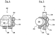
- the hydraulic distributor shown and described by way of example has a modular structure. It has a main module 202 and a plurality of load modules 204.
- the main module 202 is used for the hydraulic and electrical connection of the load modules 204 and has a control device 206 which serves as a distributor control device for controlling the plurality of load modules 204.
- the main module 202 also has an inlet connection 208 and a return connection 210. With the inlet connection 208 and the return connection 210, the main module 202 is connected to a heating or cooling system. Thereby, temperature-controlled fluid is supplied through inlet connection 208, which flows after flowing through one or more load circuits through return connection 210 back into the heating or cooling system.
- a temperature sensor can be arranged in the main module 202 on the section of the inlet line 212 and / or the section of the return line 216, which detects the inlet and the return temperature. These sensors can be signal-connected to the distribution control device 206. The distributor control device 206 can thus directly detect the temperatures in the main module.
- the hydraulic distributor is further described below using the example of a heating system. However, it should be understood that the hydraulic distributor could also be used in a cooling system or in a combined heating or cooling system.
- heated fluid in particular heated water
- the fluid flows through the return connection 210 after flowing through the heat exchangers in the rooms or objects to be heated back to the boiler or the heat accumulator.
- the inlet connection 208 is connected to an outlet 214 in the interior of the main module 202 by a section of an inlet line 212.
- the return connection 210 is connected to an inlet 218 via a section of a return line 216 inside the main module 202.
- the outlet 214 and the inlet 218 are designed as hydraulic couplings on one side of the main module 202, which face an adjacent load module 204.
- the load modules 204 also each have a section of an inlet line 212 and a section of a return line 216 in their interior. The sections of the feed line 212 and the return line 216 extend in the longitudinal direction through the load modules 204.
- the sections of the feed line 212 and the return line 216 are connected to first hydraulic couplings.
- the section of the feed line 212 at the first end is connected to a first feed coupling 220 and the section of the return line 216 on the same side is connected to a first return clutch 222.
- the first inlet clutch 220 is engaged with the outlet 214 of the main module 202, while the first return clutch 222 is engaged with the inlet 218 of the main module 202 to establish a fluid-conducting connection.
- the load modules 204 have a second inlet coupling 224 and a second return coupling 226 on one of the first inlet coupling and the longitudinal end opposite the first return coupling 222.
- the second inlet clutch 224 forms the axial end of the section of the inlet line 212 in the load module 204 opposite the first inlet clutch 220
- the second return clutch 226 forms the axial end of the section of the return line 216 in the load module 204 opposite the first return clutch 222.
- the plurality of load modules 204 are all of the same design. This means that the design and arrangement of the second inlet coupling 224 and the second return coupling 226 corresponds in its design to the arrangement of the outlet 214 and the inlet 218 on the main module 202.
- FIG. 1 An arrangement of two load modules 204 is shown, further load modules 204 being indicated schematically. In the exemplary embodiment according to Figures 2 and 3 six load modules 204 are arranged on a main module 202.
- each load module 204 has an integrated mixing device for temperature adjustment of the flow temperature for an associated load circuit 228.
- the mixing device has a regulating valve 230 in a flow path from the inlet line 212 to the inlet 229 of the load circuit 228 and a circulation pump 232 downstream thereof.
- the circulation pump 232 serves to convey fluid from the feed line 212 through the load circuit 228 and via the return line 234 back into the return line 216.
- the mixing device also has a connection from the return 234 to a mixing point 236, the mixing point 236 being located in the flow path between the regulating valve 230 and the circulation pump 232.
- a check valve 238 is located in the connection 235, which has the effect that a flow through the connection 235 is only possible in the direction from the return 234 to the mixing point 236.
- the regulating valve 230 is signal-connected to the distributor control device 206 for its activation. I.e. the distributor control device 206 controls the regulating valve 230 in order to set a desired flow temperature at the input 229 of the load circuit 228. This flow temperature at input 229 is detected by a temperature sensor 240.
- the circulation pump 232 pumps fluid exclusively via the connection 235 in the circuit through the load circuit 228.
- the circulation pump 232 simultaneously causes a fluid flow from the feed line 212 and a fluid flow from the connection 235 sucked in.
- the fluid from the feed line 212 is thus mixed with fluid from the return 234 via the connection 235, so that the flow temperature of the fluid from the feed line 212 is changed.
- the supply temperature in the supply line 212 is usually higher than in the return line 234, i.e. H. in this case, colder fluid from the return line 234 is mixed in via the connection 235 to the flow from the inlet line 212, so that the inlet temperature is reduced.
- the flow temperature of the fluid from the feed line 212 can be increased by admixing warmer fluids from the return line 235.
- the proportion of fluid which is fed from the feed line 212 to the mixing point 236 can be varied.
- a constant delivery rate of the circulation pump 232 a larger or smaller proportion of the delivery flow is sucked in via the connection 235, whereby the temperature of the fluid at the inlet 229 of the load circuit 228 can be varied by changing the mixing ratio of the two flows at the mixing point 236.
- the temperature that is actually set is detected by the temperature sensor 240.
- the detected temperature value is communicated to the distribution control device 206 for regulation via a suitable signal connection. In this way, the distributor control device 206 regulates the individual load modules 204 independently, so that the flow temperature for the individual load circuits 228 can be individually regulated or set.
- a second temperature sensor 242 is also arranged at the output of the load circuit 248.
- This is also preferably signal-connected to the distributor control device 206 and detects the outlet temperature from the load circuit 228. Since the inlet and outlet temperatures of the load circuit 228 are detected in this way, it is possible to determine the temperature difference across the load circuit 228 and, for example, that of of the circulating pump 232 to regulate the volume flow depending on this temperature difference.
- the circulation pump 232 is preferably also controlled by the control device 206 via a suitable signal connection, in particular in order to set the speed of the circulation pump 232. The flow can be set individually for each load circuit by changing the speed of the respective circulation pump 232.
- the constructive structure of the on the basis of Fig. 1 described hydraulic distributor is based on the Figures 2 to 7 described.
- the main module 202 has a hydraulic section 250 and an electronics housing 252, in which the control device or distributor control device 206 and possibly further components for energy supply, such as a power supply unit, are arranged.
- the hydraulic section 250 is preferably designed as a one-piece component made of plastic and has the inlet connection 208 and the return connection 210 on one side.
- the inlet connection 208 and the return connection 210 are designed as hydraulic couplings for connecting supply lines which establish the connection to a heating or cooling system.
- the inlet 218 and the outlet 214 are arranged on a second side surface of the hydraulic section 250.
- the outlet 214 is connected to the inlet connection 208 via a channel inside the hydraulic section 250, while the inlet 218 is connected to the return connection 210 via another channel inside the hydraulic section 250.
- the outlet 214 and the inlet 218 are designed as hydraulic couplings for the pluggable connection of a load module 204.
- the first inlet clutch 220 of an adjacent load module 204 engages in the outlet 214 and a first return clutch 220 of an adjacent load module in the inlet 218.
- the outlet 214 and the inlet 218 are each formed as female parts of a plug-in coupling.
- the first inlet clutch 220 and the first return clutch 222 are each designed as the male parts of a hydraulic plug-in coupling.
- the load module 204 also has a housing part made in one piece from plastic, which serves as a pump housing for the circulation pump 232 and has the required flow paths and in particular the sections of the feed line 212 and the return line 216 in its interior.
- the drive of the regulating valve 230 and the stator housing 256 of the circulation pump 232 project outwards from the housing part 254.
- the housing part 254 has the first inlet coupling 220 and the first return coupling 222 at one longitudinal end and the second inlet coupling 224 and the second return coupling 226 at an opposite longitudinal end, the second inlet coupling 224 and the second return coupling 226 corresponding to the outlet 214 and the inlet 218 are formed on the main module 202 as female parts of a hydraulic plug-in coupling.
- the second inlet coupling 224 and the second return coupling 226 are shaped and arranged corresponding to the outlet 214 and the inlet 218, it is possible to connect identically designed load modules 204 either directly to the main module 202 or to a further load module 204, in which case the first inlet coupling 220 of a second load module engages in the second inlet clutch 224 of a first load module and the first return clutch 222 of a second load module in the second return clutch 226 of a first load module. In this way, several load modules can be plugged together to form a hydraulic distributor with the desired number of connections for load circuits 228.
- the number of load modules 204 is essentially limited by the configuration of control device 206.
- the housing part 254 of the load module 204 also has an inlet connection 258 and a return connection 260.
- the inlet connection 258 connects the input 229 of a load circuit 228, while the outlet connection 260 connects an output 231 of the load circuit 228.
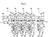
- FIGS Figures 2 and 3 show the assembled arrangement of six load modules 204 on the main module 202 as shown in FIGS Figures 4 and 5 are shown. It can be seen that such a hydraulic distributor is created, which has six inlet connections 256 and six return connections 260 for six load circuits. All six load modules 204 are of identical design. The last, ie the load module 204 facing away from the main module 202, is closed at its second inlet coupling 224 and its second return coupling 226 by an end piece 262.
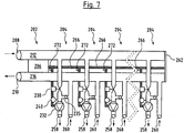
- FIG. 7 shows the structure according to Fig. 7 in the non-assembled state of the load modules 204.
- Figures 6 and 7 only the arrangement of four load modules 204 is shown schematically.
- the main module 202 and the load modules 204 have electrical or electronic components.
- the load module has the electronic control device 206. This is connected in the main module 202 to an electrical connector 264.
- an electrical connection 266 is provided, which ends in an electrical connector 268 at a first axial end and in an electrical connector 270 at the opposite axial end.
- the electrical connector 268 and 270 are configured so that the electrical connector 268 can engage the electrical connector 264 on the main module 202 or an electrical connector 270 of an adjacent load module to form an electrical coupling and an electrical connection between the Load module 204 and an adjacent load module 204 or the main module 202 to manufacture.
- the drive of the regulating valve 230, the temperature sensor 240 and the circulation pump 232 are connected to the electrical connection 266, which is designed as a data bus, in the interior of the load module 204.
- the electrical connection 266 serves for the energy transmission to these components and also for the signal transmission to these components or from these components to the distributor control device 206 in the main module 202.
- each load module 204 is plugged into a load module 204, an energy supply of this subsequent load module 204 from the main module 202 as well as a data transmission from the main module 202 to this further load module 204 via the or the intermediate load modules 204 are manufactured.
- the individual load modules 204 can be addressed via a module control device 272 in each load module 204.
- the module control device 272 is used for data communication with the central distributor control device 206.
- each module control device 272 that is to say each load module 204, is assigned an address. This can be done automatically by the distribution control device 206 when the respective load module 204 is connected.
- the regulating valve 230 and the circulation pump 232 in each load module 204 can then be individually controlled by the distributor control device 206 in order to bring about temperature and volume flow control for the connected load circuit.
- the output signal of the temperature sensor 240 and possibly the temperature sensor 242 is reported back to the distributor control device 206 via the module control device 272 and can be incorporated there into the regulation of the respective load module 204.
- room thermostats 274 are provided in the rooms to be tempered (see Fig. 1 ).
- the room thermostats 274 communicate with a communication interface 276 of the control device 206.
- a desired target temperature can be set on the room thermostats 274. If the actual temperature deviates from this target temperature, the room thermostat 274 sends a corresponding signal to the communication sections 276 of the control device 206. The latter then activates the load circuit 228 associated with the room by switching on the circulation pump 232 in the associated load module 204 Temperature and flow control for the associated load circuit 228. If the entered target temperature is reached at the room thermostat 274, the room thermostat 274 sends a corresponding signal to the communication interface 276 of the control device 206. The latter then deactivates the associated load circuit 228, ie switches that in the respective room located load circuit 228 by the circulation pump 232 is switched off in the associated load module 204.
Description
Die Erfindung betrifft einen hydraulischen Verteiler für ein hydraulisches Heizungs- und/oder Kühlsystem mit den im Oberbegriff des Anspruchs 1 angegebenen Merkmalen.The invention relates to a hydraulic distributor for a hydraulic heating and / or cooling system with the features specified in the preamble of
Beispielsweise in Fußbodenheizungsanlagen sind hydraulische Verteiler bekannt, von denen aus sich die einzelnen Lastkreise bzw. Fußbodenheizungskreise erstrecken. Der hydraulische Verteiler stellt dabei die Verbindung einer Mehrzahl von Lastkreisen zu dem Heizungssystem her. Die bekannten Verteiler sind in der Regel im Wesentlichen aus zwei Rohren ausgebildet, von denen eines als Zulauf und das andere als Rücklauf fungiert. An den Rohren sind Anschlüsse für die einzelnen Lastkreise angeordnet. Dabei ist jeder Lastkreis mit einem Anschluss an dem Zulauf und einem Anschluss an dem Rücklauf verbunden.Hydraulic distributors are known, for example, in underfloor heating systems, from which the individual load circuits or underfloor heating circuits extend. The hydraulic distributor connects a plurality of load circuits to the heating system. The known distributors are generally essentially made up of two pipes, one of which functions as an inlet and the other as a return. Connections for the individual load circuits are arranged on the pipes. Each load circuit is connected to a connection on the inlet and a connection on the return.
Darüber hinaus ist es in Fußbodenheizungsanlagen bekannt, Mischeinrichtungen bzw. Mischer zu verwenden, welche dem als Wärmeträger fungierenden Fluid im Zulauf kälteres Wasser aus dem Rücklauf zumischt, um die Vorlauftemperatur zu senken. Derartige Mischer sind insbesondere dann erforderlich, wenn die Fußbodenheizung in Kombination mit normalen Heizkörpern verwendet wird, da die Fußbodenheizung eine niedrigere Vorlauftemperatur benötigt als normale Heizkörper. In bekannten Fußbodenheizungssystemen wird dabei ein zentraler Mischer verwendet, welcher stromaufwärts des hydraulischen Verteilers bzw. des Zulaufs in dem hydraulischen Verteiler angeordnet ist. Die von dem Mischer bereitgestellte Vorlauftemperatur für die Fußbodenheizung wird entweder in Abhängigkeit eines Raumtemperaturfühlers in einem Raum oder außentemperaturabhängig eingestellt. Die Temperatur der zu beheizenden Räume wird üblicherweise durch Öffnen und Schließen der einzelnen Kreise der Fußbodenheizung eingestellt.In addition, it is known in underfloor heating systems to use mixing devices or mixers which admix colder water from the return line to the fluid acting as a heat carrier in order to lower the flow temperature. Such mixers are particularly necessary when the underfloor heating is used in combination with normal radiators, since the underfloor heating requires a lower flow temperature than normal radiators. In known floor heating systems, a central mixer is used, which is arranged upstream of the hydraulic distributor or the inlet in the hydraulic distributor. The flow temperature for the underfloor heating provided by the mixer is set either as a function of a room temperature sensor in a room or as a function of the outside temperature. The temperature of the rooms to be heated is usually set by opening and closing the individual circles of the underfloor heating.
Es ist Aufgabe der Erfindung, ein Heizungs- und/oder Kühlsystem dahingehend zu verbessern, dass auf der einen Seite der Energieverbrauch reduziert werden kann und der Heiz- und/oder Kühlkomfort in zu temperierenden Räumen verbessert werden kann und auf der anderen Seite eine einfache Anpassung des Systems an eine gewünschte Zahl zu temperierender Bereiche möglich ist.It is an object of the invention to improve a heating and / or cooling system in such a way that on the one hand the energy consumption can be reduced and the heating and / or cooling comfort in rooms to be tempered can be improved and on the other hand a simple adjustment the system to a desired number of areas to be tempered.
Diese Aufgabe wird durch einen hydraulischen Verteiler für ein hydraulisches Heizungs- und/oder Kühlsystem mit den in Anspruch 1 angegebenen Merkmalen gelöst. Bevorzugte Ausführungsformen ergeben sich aus den Unteransprüchen, der Beschreibung sowie den Figuren.This object is achieved by a hydraulic distributor for a hydraulic heating and / or cooling system with the features specified in
Der erfindungsgemäße hydraulische Verteiler ist zur Verwendung in einem hydraulischen Heizungs- und/oder Kühlsystem vorgesehen, welches ein Rohrleitungssystem aufweist, in welchem ein flüssiger Wärmeträger, wie z. B. Wasser zirkuliert. Dabei kann es sich entweder um ein ausschließliches Heizungssystem, wie beispielsweise eine Fußbodenheizung, oder ein ausschließliches Kühlsystem oder auch ein kombiniertes System handeln, welches sowohl ein Kühlen als auch ein Heizen von Objekten oder Räumen zulässt. So kann das System beispielsweise im Winter als Heizung und im Sommer zur Kühlung bzw. Klimatisierung dienen.The hydraulic distributor according to the invention is intended for use in a hydraulic heating and / or cooling system which has a pipeline system in which a liquid heat transfer medium, such as, for. B. water circulates. This can be either an exclusive heating system, such as underfloor heating, or an exclusive cooling system or a combined system that allows both cooling and heating of objects or rooms. For example, the system can be used as heating in winter and for cooling or air conditioning in summer.
Der hydraulische Verteiler gemäß der Erfindung weist eine Zulaufleitung und eine Rücklaufleitung auf, wobei die Zulaufleitung mindestens einen Zulaufanschluss und die Rücklaufleitung zumindest einen Rücklaufanschluss aufweist. Der Zulaufanschluss und der Rücklaufanschluss dienen dazu einen Lastkreis, beispielsweise einen Fußbodenheizungskreis anzuschließen. Dabei wird der Zulauf bzw. der Eingang des Lastkreises mit dem Zulaufanschluss und der Ausgang bzw. Rücklauf des Lastkreises mit dem Rücklaufanschluss verbunden. Bevorzugt sind an der Zulaufleitung mehrere Zulaufanschlüsse und an der Rücklaufleitung mehrere Rücklaufanschlüsse ausgebildet, um mehrere Lastkreise an den hydraulischen Verteiler anschließen zu können.The hydraulic distributor according to the invention has an inlet line and a return line, the inlet line having at least one inlet connection and the return line having at least one return connection. The inlet connection and the return connection serve to connect a load circuit, for example an underfloor heating circuit. The inlet or the input of the load circuit is connected to the inlet connection and the outlet or return of the load circuit to the return connection. A plurality of inlet connections are preferably formed on the inlet line and a plurality of return connections are formed on the return line in order to be able to connect a plurality of load circuits to the hydraulic distributor.
Der erfindungsgemäße hydraulische Verteiler weist mehrere Lastmodule auf, in welchen jeweils ein Abschnitt der Zulaufleitung mit zumindest einem Zulaufanschluss und ein Abschnitt der Rücklaufleitung mit einem Rücklaufanschluss ausgebildet sind. D. h. die Lastmodule dienen dazu, jeweils einen Lastkreis an den Verteiler anzuschließen. Die Lastmodule weisen erfindungsgemäß jeweils eine Mischeinrichtung mit einer Pumpe und einem Regulierventil auf, welche ausgebildet sind, einem Fluidstrom von der Zulaufleitung zu dem Zulaufanschluss Fluid aus dem Rücklaufanschluss zuzumischen. Eine derartige Mischeinrichtung dient dazu, im Falle eines Heizungssystems die Vorlauftemperatur des Fluids bzw. der Flüssigkeit aus der Zulaufleitung durch Zumischen kälterer Flüssigkeit aus dem Rücklaufanschluss zu reduzieren. Umgekehrt kann im Falle eines Kühlsystems die Mischeinrichtung dazu genutzt werden, die Vorlauftemperatur einer durch die Zulaufleitung zuströmenden kalten Flüssigkeit durch Zumischen von wärmerer Flüssigkeit aus dem Rücklaufanschluss zu erhöhen. So kann mittels der Mischeinrichtung die Vorlauftemperatur der als Wärmeträger dienenden Flüssigkeit für den an das Lastmodul angeschlossenen Lastkreis individuell eingestellt werden. Zur Einstellung dient das Regulierventil, welches so angeordnet ist, dass durch seine Betätigung der Grad der Zumischung von Flüssigkeit aus dem Rücklaufanschluss variiert werden kann. So ist eine Temperatureinstellung bzw. Temperaturregelung für den Lastkreis möglich. Die Anordnung der Mischeinrichtung direkt an dem Lastkreis hat den Vorteil, dass eine individuelle Temperaturanpassung für diesen Lastkreis möglich ist, welche bei einem zentralen Mischer nicht möglich ist. Darüber hinaus hat die Anordnung der Mischeinrichtung in dem hydraulischen Verteiler den Vorteil, dass die Zuleitung zu dem hydraulischen Verteiler ohne Probleme in ein normales Heizungs- und/oder Kühlsystem eingebunden werden kann. Beispielsweise ist es bei einer Heizungsanlage nicht erforderlich von einem zentralen Mischer eine separate Zuleitung zu dem hydraulischen Verteiler zu legen. Vielmehr kann der hydraulische Verteiler an übliche Heizungsleitungen, welche beispielsweise zu Heizkörpern führen, angeschlossen werden. So vereinfacht sich die Installation.The hydraulic distributor according to the invention has a plurality of load modules, in each of which a section of the inlet line with at least one inlet connection and a section of the return line with a return connection are formed. I.e. the load modules are used to connect one load circuit to the distributor. According to the invention, the load modules each have a mixing device with a pump and a regulating valve, which are designed to mix fluid from the return line to a fluid flow from the inlet line to the inlet connection. In the case of a heating system, such a mixing device serves to reduce the flow temperature of the fluid or the liquid from the feed line by adding colder liquid from the return connection. Conversely, in the case of a cooling system, the mixing device can be used to increase the flow temperature of a cold liquid flowing through the supply line by admixing warmer liquid from the return connection. Thus, the flow temperature of the liquid serving as heat transfer medium for the load circuit connected to the load module can be set individually by means of the mixing device. The regulating valve, which is arranged in such a way that the degree of admixing of liquid from the return connection can be varied by its actuation. A temperature setting or temperature control for the load circuit is possible. The arrangement of the mixing device directly on the load circuit has the advantage that an individual temperature adjustment for this load circuit is possible, which is not possible with a central mixer. In addition, the arrangement of the mixing device in the hydraulic distributor has the advantage that the feed line to the hydraulic distributor can be integrated into a normal heating and / or cooling system without problems. For example, a heating system does not require a separate feed line to the central mixer hydraulic distributor. Rather, the hydraulic distributor can be connected to conventional heating lines, which lead to radiators, for example. This simplifies the installation.
Ferner weisen die Lastmodule jeweils Anschlüsse für ein weiteres Lastmodul auf. So weist der Abschnitt der Zulaufleitung einen zusätzlichen Anschluss auf und der Abschnitt der Rücklaufleitung weist einen zusätzlichen Anschluss auf, welche jeweils mit entsprechenden korrespondierenden Anschlüssen eines weiteren, vorzugsweise identischen Lastmoduls verbunden werden können. Diese zusätzlichen Anschlüsse sind vorzugsweise als hydraulische Kupplungen ausgestaltet, wie Sie unten beschrieben werden. So ist es möglich, mehrere Lastmodule aneinander zu reihen, wobei die Abschnitte der Zulaufleitung und die Abschnitte der Rücklaufleitung der jeweiligen Lastmodule über die zusätzlichen Anschlüsse miteinander verbunden werden.Furthermore, the load modules each have connections for a further load module. The section of the feed line has an additional connection and the section of the return line has an additional connection, which can each be connected to corresponding corresponding connections of a further, preferably identical load module. These additional connections are preferably designed as hydraulic couplings, as described below. It is thus possible to line up several load modules, the sections of the inlet line and the sections of the return line of the respective load modules being connected to one another via the additional connections.
Der Verteiler weist mehrere, vorzugsweise lösbar miteinander derart verbundene Lastmodule auf, dass die Abschnitte der Zulaufleitung jeweils miteinander verbunden und die Abschnitte der Rücklaufleitung jeweils miteinander verbunden sind. Bevorzugt ist für jeden Lastkreis ein separates Lastmodul mit einer Mischeinrichtung vorgesehen. So kann für jeden Lastkreis die Vorlauftemperatur individuell eingestellt und an den Wärme- bzw. Kältebedarf des einzelnen Lastkreises angepasst werden. Damit ist eine individuelle Regelung für die einzelnen Lastkreise bzw. für von den Lastkreisen zu temperierende Räume möglich, woraus sich Energieeinsparungen und ein Komfortgewinn ergeben. Der modulare Aufbau des erfindungsgemäßen hydraulischen Verteilers mit einzelnen Lastmodulen hat den Vorteil, dass der hydraulische Verteiler leicht an die erforderliche Zahl von Lastkreisen angepasst werden kann, so dass für unterschiedliche Zahlen von Lastkreisen nicht spezielle hydraulische Verteiler vorgehalten werden müssen. Es können vielmehr Lastmodule in der erforderlichen Zahl miteinander verbunden werden, um einen hydraulischen Verteiler mit der gewünschten Zahl von Lastmodulen aufzubauen. Die Lastmodule sind vorzugsweise lösbar miteinander verbunden, so dass sie im Falle von Defekten leicht ausgetauscht werden können. So ist es nicht erforderlich, den gesamten hydraulischen Verteiler auszutauschen.The distributor has a plurality of load modules, preferably releasably connected to one another in such a way that the sections of the feed line are each connected to one another and the sections of the return line are each connected to one another. A separate load module with a mixing device is preferably provided for each load circuit. The flow temperature can be individually set for each load circuit and adapted to the heating and cooling requirements of the individual load circuit. This enables individual control for the individual load circuits or for rooms to be temperature-controlled by the load circuits, which results in energy savings and a gain in comfort. The modular structure of the hydraulic distributor according to the invention with individual load modules has the advantage that the hydraulic distributor can easily be adapted to the required number of load circuits, so that special hydraulic distributors do not have to be provided for different numbers of load circuits. Rather, the required number of load modules can be connected to one another, to build a hydraulic distributor with the desired number of load modules. The load modules are preferably releasably connected to one another so that they can be easily replaced in the event of defects. It is therefore not necessary to replace the entire hydraulic distributor.
Weiter bevorzugt sind die Lastmodule, vorzugsweise lösbar mit einem Hauptmodul verbunden, welches eine Steuereinrichtung und/oder einen Eingang für die Zulaufleitung und/oder einen Ausgang für die Rücklaufleitung aufweist. D. h. das Hauptmodul dient vorzugsweise dem Anschluss des hydraulischen Verteilers an Versorgungsleitungen, welche den Zulauf und den Rücklauf zu dem hydraulischen Verteiler von einer Heizungs- oder Kühlanlage herstellen. Das zumindest eine Lastmodul ist vorzugsweise mit dem Hauptmodul so verbunden, dass der Abschnitt der Zulaufleitung in dem Lastmodul mit einem Eingang für die Zulaufleitung an dem Hauptmodul fluidleitend verbunden ist. Alternativ oder zusätzlich kann der Abschnitt der Rücklaufleitung in dem Lastmodul mit dem Ausgang für die Rücklaufleitung an dem Hauptmodul fluidleitend verbunden sein. Bevorzugt sind sowohl der Abschnitt der Zulaufleitung als auch der Abschnitt der Rücklaufleitung in dem Lastmodul mit dem Hauptmodul in der genannten Weise hydraulisch verbunden. Die hydraulische Verbindung wird bevorzugt über lösbare Kupplungen, insbesondere Steckkupplungen hergestellt. Bevorzugt sind die Lastmodule derart ausgestaltet, dass sie an einer Seite hydraulische Kupplungen zur Verbindung mit dem Hauptmodul und an einem entgegengesetzten Ende hydraulische Kupplungen zur Verbindung mit einem weiteren Lastmodul aufweisen. Dabei sind die hydraulischen Kupplungen zur Verbindung mit einem weiteren Lastmodul zweckmäßigerweise identisch zu den hydraulischen Kupplungen an dem Hauptmodul ausgebildet. So können mehrere Lastmodule in Reihe aneinandergesteckt werden, wobei vorzugsweise die Abschnitte der Zulaufleitung und die Abschnitte der Rücklaufleitung der zusammengesteckten Lastmodule eine durchgehende Zulaufleitung und eine durchgehende Rücklaufleitung bilden. Dies ermöglicht den Aufbau eines hydraulischen Verteilers unterschiedlicher Länge, je nachdem wie viele Lastmodule aneinandergereiht werden.The load modules are further preferably connected, preferably detachably, to a main module which has a control device and / or an input for the feed line and / or an output for the return line. I.e. the main module is preferably used to connect the hydraulic distributor to supply lines which produce the inlet and the return to the hydraulic distributor from a heating or cooling system. The at least one load module is preferably connected to the main module such that the section of the feed line in the load module is fluidly connected to an input for the feed line on the main module. Alternatively or additionally, the section of the return line in the load module can be connected in a fluid-conducting manner to the outlet for the return line on the main module. Both the section of the inlet line and the section of the return line in the load module are preferably hydraulically connected to the main module in the manner mentioned. The hydraulic connection is preferably established via detachable couplings, in particular plug-in couplings. The load modules are preferably designed in such a way that they have hydraulic couplings for connection to the main module on one side and hydraulic couplings for connection to a further load module at an opposite end. The hydraulic couplings for connection to a further load module are expediently designed identically to the hydraulic couplings on the main module. So several load modules can be plugged together in series, preferably the sections of the Inlet line and the sections of the return line of the assembled load modules form a continuous inlet line and a continuous return line. This enables the construction of a hydraulic distributor of different lengths, depending on how many load modules are strung together.
Alternativ oder zusätzlich kann das Hauptmodul eine Steuereinrichtung aufweisen, beispielsweise eine Verteiler-Steuereinrichtung, wie sie nachfolgend beschrieben wird. In dem Hauptmodul können darüber hinaus bevorzugt Sensoren angeordnet sein, beispielsweise Temperaturfühler, welche die Temperatur in der Zulaufleitung und/oder der Rücklaufleitung erfassen. Derartige Sensoren können mit der Steuereinrichtung signalverbunden sein, sodass die Steuereinrichtung die Temperaturen direkt in dem Hauptmodul erfassen kann.Alternatively or additionally, the main module can have a control device, for example a distributor control device, as will be described below. In addition, sensors can preferably be arranged in the main module, for example temperature sensors, which detect the temperature in the inlet line and / or the return line. Such sensors can be signal-connected to the control device, so that the control device can detect the temperatures directly in the main module.
Erfindungsgemäß ist eine Verteiler-Steuereinrichtung vorhanden, welche zur Steuerung der Regulierventile und/oder der Pumpen in den mehreren Lastmodulen ausgebildet ist. Die Anordnung einer zentralen Verteiler-Steuereinrichtung, welche die Mischeinrichtungen der Lastmodule steuert, hat jedoch den Vorteil, dass lediglich eine Steuereinrichtung für mehrere Lastmodule vorgesehen werden muss. Darüber hinaus kann die Steuerung mehrere Lastmodule im Zusammenhang steuern bzw. regeln, beispielsweise um sicherzustellen, dass die zur Verfügung stehende Heiz- oder Kühlenergie in gewünschter Weise auf die mehreren Lastkreise verteilt wird. Durch die Steuerung des Regulierventils wird in der oben beschriebenen Weise der Zumischgrad von Flüssigkeit bzw. Fluid aus dem Rücklauf zu dem Zulauf eingestellt. Die Steuerung kann ferner beispielsweise dergestalt sein, dass die Verteiler-Steuereinrichtung die Pumpe ein- und ausschaltet, um den zugehörigen Lastkreis ein- und auszuschalten. Besonders bevorzugt ist eine Drehzahlregelung der Pumpe vorgesehen, wodurch zusätzlich der Durchfluss bzw. Volumenstrom durch den Lastkreis von der Verteiler-Steuereinrichtung eingestellt werden kann, so dass die Menge des zugeführten Wärmeträgers, d. h. Fluids an den Bedarf des jeweiligen Lastkreises durch die Regelung der Pumpe angepasst werden kann.According to the invention, there is a distributor control device which is designed to control the regulating valves and / or the pumps in the plurality of load modules. However, the arrangement of a central distributor control device which controls the mixing devices of the load modules has the advantage that only one control device has to be provided for a plurality of load modules. In addition, the control can control or regulate several load modules in connection, for example to ensure that the available heating or cooling energy is distributed in the desired manner to the several load circuits. By controlling the regulating valve, the degree of admixture of liquid or fluid from the return to the inlet is set in the manner described above. The control can also be such that the distributor control device switches the pump on and off in order to switch the associated load circuit on and off. A speed control of the pump is particularly preferably provided, as a result of which the flow rate or volume flow through the load circuit can also be set by the distributor control device, so that the amount of heat carrier supplied, ie. H. Fluids can be adapted to the needs of the respective load circuit by controlling the pump.
Die Verteiler-Steuereinrichtung ist mit den Lastmodulen bzw. den in den Lastmodulen angeordneten elektrischen Bauteilen, nämlich der Pumpe und/oder dem Regulierventil signalverbunden, wobei die Verbindung insbesondere über einen Datenbus erfolgt. So ist eine Übertragung von Steuersignalen von der Verteilersteuereinrichtung zu dem Lastmodul bzw. deren zu steuernden bzw. zu regelnden Komponenten möglich. Über die Signalverbindung kann weiter bevorzugt in umgekehrter Richtung eine Übertragung von Zustandsdaten oder Sensorsignalen erfolgen. Beispielsweise können Rückmeldungen über den Betriebszustand des Regulierventils und/oder der Pumpe an die Verteiler-Steuereinrichtung erfolgen. Beispielsweise können der Öffnungsgrad des Regulierventils oder die aktuelle Drehzahl der Pumpe zurückgemeldet werden. Besonders bevorzugt können in den Lastmodulen zusätzliche Sensoren, beispielsweise Temperatursensoren vorgesehen sein, deren Signale an die Verteiler-Steuereinrichtung übertragen werden. Z. B. kann ein Temperatursensor im Rücklaufanschluss bzw. im Strömungsweg zwischen dem Rücklaufanschluss und dem Abschnitt der Rücklaufleitung in dem Lastmodul angeordnet sein, um die Austrittstemperatur des Wärmeträgers bzw. Fluids aus dem Lastkreis zu erfassen. Die Signalverbindung über einen Datenbus ist insbesondere dann von Vorteil, wenn unterschiedliche Zahlen von Lastmodulen in der oben beschriebenen Weise aneinandergereiht werden sollen. Ein solcher Datenbus, welcher sich dann vorzugsweise über alle Lastmodule erstreckt, ermöglicht es, Signale über einzelne Lastmodule an andere Lastmodule weiterzuleiten.The distributor control device is signal-connected to the load modules or the electrical components arranged in the load modules, namely the pump and / or the regulating valve, the connection taking place in particular via a data bus. It is thus possible to transmit control signals from the distributor control device to the load module or its components to be controlled or regulated. Status data or sensor signals can also be transmitted in the opposite direction via the signal connection. For example, feedback about the operating state of the regulating valve and / or the pump can be sent to the distributor control device. For example, the degree of opening of the regulating valve or the current speed of the pump can be reported back. Additional sensors, for example temperature sensors, whose signals are transmitted to the distributor control device, can be particularly preferably provided in the load modules. For example, a temperature sensor can be arranged in the return connection or in the flow path between the return connection and the section of the return line in the load module in order to detect the outlet temperature of the heat transfer medium or fluid from the load circuit. The signal connection via a data bus is particularly advantageous when different numbers of load modules are to be strung together in the manner described above. Such a data bus, which then preferably extends over all load modules, enables signals to be forwarded to other load modules via individual load modules.
Jedes Lastmodul weist vorzugsweise eine Modul-Steuereinrichtung bzw. eine Kommunikationseinheit auf, welche von der Verteiler-Steuereinrichtung eindeutig adressierbar ist, um Daten und/oder Signale mit dem Lastmodul austauschen zu können. Die Adressierung erfolgt vorzugsweise automatisch. Besonders bevorzugt ist die Verteiler-Steuereinrichtung so ausgebildet, dass sie ein angeschlossenes Lastmodul erkennt und dem Lastmodul bzw. dessen Modul-Steuereinrichtung automatisiert eine Adresse zuweist. Alternativ oder zusätzlich können an der Verteiler-Steuereinrichtung und/oder dem Lastmodul Betätigungselemente vorgesehen sein, welche eine manuelle Aktivierung der Koppelprozedur ermöglicht.Each load module preferably has a module control device or a communication unit which can be uniquely addressed by the distribution control device in order to be able to exchange data and / or signals with the load module. Addressing is preferably done automatically. The distributor control device is particularly preferably designed such that it detects a connected load module and automatically assigns an address to the load module or its module control device. As an alternative or in addition, actuation elements can be provided on the distributor control device and / or the load module, which enable a manual activation of the coupling procedure.
Besonders bevorzugt ist die Verteiler-Steuereinrichtung in dem Hauptmodul angeordnet. Das Hauptmodul bildet somit neben dem hydraulischen Anschluss für die Lastmodule auch die zentrale Steuereinrichtung für bevorzugt den gesamten hydraulischen Verteiler. Zur elektrischen bzw. Signal-Verbindung zwischen Hauptmodul und Lastmodul können entsprechende elektrische Verbindungen, insbesondere lösbare Steckverbindungen vorhanden sein. Weiter bevorzugt weisen die Lastmodule auch an einem dem Hauptmodul entgegengesetzten Längsende entsprechende elektrische Steckverbindungen auf, welche die elektrische Verbindung mit einem angrenzenden weiteren Lastmodul ermöglichen. So kann sich eine elektrische Versorgungsleitung für die elektrischen Komponenten der Lastmodule ausgehend von dem Hauptmodul über die Steckverbindungen durch alle Lastmodule hindurch erstrecken. Gleichzeitig kann sich auf diese Weise ein Datenbus ausgehend von dem Hauptmodul durch die einzelnen Lastmodule hindurch erstrecken. Der Datenbus kann dabei ebenfalls über eine elektrische Verbindung, oder aber auch über eine andere geeignete Verbindung, beispielsweise eine optische Verbindung erfolgen. Gemäß einer besonders bevorzugten Ausführungsform der Erfindung ist in dem zumindest einen Lastmodul zumindest ein Temperatursensor angeordnet, welcher mit der Verteiler-Steuereinrichtung, insbesondere über einen Datenbus signalverbunden ist. Dies kann beispielsweise wie oben beschreiben ein Temperatursensor im Rücklauf des Lastkreises sein.The distributor control device is particularly preferably arranged in the main module. In addition to the hydraulic connection for the load modules, the main module thus also forms the central control device for preferably the entire hydraulic distributor. Corresponding electrical connections, in particular detachable plug connections, can be provided for the electrical or signal connection between the main module and the load module. More preferably, the load modules also have corresponding electrical plug connections on a longitudinal end opposite the main module, which enable the electrical connection to an adjacent further load module. For example, an electrical supply line for the electrical components of the load modules can extend from the main module via the plug connections through all load modules. At the same time, a data bus can extend from the main module through the individual load modules in this way. The data bus can also take place via an electrical connection, or else via another suitable connection, for example an optical connection. According to a particularly preferred embodiment of the invention, at least one temperature sensor is arranged in the at least one load module, which is signal-connected to the distributor control device, in particular via a data bus. As described above, this can be, for example, a temperature sensor in the return of the load circuit.
Bevorzugt ist jeweils ein Temperatursensor in den Lastmodulen derart angeordnet, dass er die Temperatur eines durch den Zulaufanschluss in den angeschlossenen Lastkreis zu strömenden Fluids erfasst. D. h. ein Temperatursensor ist bevorzugt im Strömungsweg von der Mischeinrichtung zu dem Zulaufanschluss gelegen, so dass er die Temperatur des von der Mischeinrichtung gemischten Fluids erfasst. Dies ermöglicht eine Temperaturregelung über die Verteiler-Steuereinrichtung, da die über das Regulierventil in dem Lastmodul eingestellte Temperatur von dem Temperatursensor erfasst wird und so eine Rückmeldung an die Steuereinrichtung gegeben wird. Zusätzlich kann ein weiterer Temperatursensor wie beschrieben im Rücklauf vorgesehen sein.A temperature sensor is preferably arranged in each case in the load modules in such a way that it detects the temperature of a fluid to flow through the inlet connection into the connected load circuit. I.e. a temperature sensor is preferably located in the flow path from the mixing device to the inlet connection, so that it detects the temperature of the fluid mixed by the mixing device. This enables temperature control via the distributor control device, since the temperature set via the regulating valve in the load module is detected by the temperature sensor and feedback is thus given to the control device. In addition, a further temperature sensor can be provided in the return as described.
Bevorzugt ist die Verteiler-Steuereinrichtung bevorzugt dazu ausgebildet, durch Ansteuerung der Regulierventile in den Lastmodulen die Temperatur eines Fluidstroms durch den Zulaufanschluss einzustellen. Dies erfolgt dabei bevorzugt im Zusammenspiel mit dem vorangehend beschriebenen Temperatursensor. Besonders bevorzugt steuert bzw. regelt die Verteiler-Steuereinrichtung die Regulierventile mehrerer Lastmodule, so dass die Temperaturen an den Zulaufanschlüssen der einzelnen Lastmodule zentral von der Verteiler-Steuereinrichtung eingestellt werden können.The distributor control device is preferably designed to set the temperature of a fluid flow through the inlet connection by controlling the regulating valves in the load modules. This is preferably done in Interaction with the temperature sensor described above. The distributor control device particularly preferably controls the regulating valves of a plurality of load modules, so that the temperatures at the inlet connections of the individual load modules can be set centrally by the distributor control device.
Weiter bevorzugt ist die Verteiler-Steuereinrichtung dazu ausgebildet, durch Ansteuerung der Pumpen in den Lastmodulen einen Fluidstrom bzw. Volumenstrom durch den Zulaufanschluss in den angeschlossenen Lastkreis einzustellen. Für die mehreren Lastmodule erfolgt auch hier die Ansteuerung der Pumpen mehrerer, vorzugsweise sämtlicher Lastmodule von der Verteiler-Steuereinrichtung, so dass diese als zentrale Steuerung sämtlicher Lastkreise fungiert und insbesondere die Fluidströme durch die einzelnen Lastkreise aneinander angepasst einstellen kann. Bevorzugt erfolgt dies, wie oben beschrieben, durch Drehzahlregelung der einzelnen Pumpen.The distributor control device is further preferably designed to set a fluid flow or volume flow through the inlet connection into the connected load circuit by actuating the pumps in the load modules. For the multiple load modules, the pumps of a plurality, preferably all, of the load modules are also controlled by the distributor control device, so that it functions as a central control of all the load circuits and, in particular, can adjust the fluid flows through the individual load circuits to one another. As described above, this is preferably done by controlling the speed of the individual pumps.
Gemäß einer weiteren bevorzugten Ausführungsform weist die Verteiler-Steuereinrichtung zumindest eine Kommunikationsschnittstelle zum Empfang von Signalen von zumindest einem externen Steuerelement, insbesondere einem Raumthermostaten auf. So ist es möglich, in den von den Lastkreisen zu temperierenden Räumen Raumthermostate anzuordnen, welche die aktuelle Temperatur in den Räumen erfassen und die Temperaturwerte ggf. an die Verteiler-Steuereinrichtung übertragen. Besonders bevorzugt sind die Raumthermostate so ausgebildet, dass sie die Einstellung einer Solltemperatur für den jeweiligen Raum ermöglichen. Bei Abweichung von dieser Solltemperatur sendet der Raumthermostat über die Kommunikationsschnittstelle ein entsprechendes Signal an die Verteiler-Steuereinrichtung, welche dann in Abhängigkeit entsprechend den oder die zu dem Raum zugehörigen Lastkreise aktiviert, in diesem Lastkreis wird dazu beispielsweise die beschriebene Pumpe eingeschaltet und es wird dann über Ansteuerung des oder der Regulierventile die Anpassung der Vorlauftemperatur in den Lastkreisen vorgenommen. Die Kommunikationsschnittstelle kann als drahtgebundene Schnittstelle oder beispielsweise auch als Funkschnittstelle ausgebildet sein. Bevorzugt kommunizieren mehrere Steuerelement, insbesondere mehrere Raumthermostate mit der Kommunikationsschnittstelle der Verteiler-Steuereinrichtung. Eine Zuordnung der einzelnen Raumthermostate zu den angeschlossenen Lastmodulen wird entsprechend in der Steuereinrichtung hinterlegt bzw. eingestellt. Gemäß einer weiteren bevorzugten Ausführungsform der Erfindung weist das Hauptmodul eine Energieversorgung für die Pumpe und/oder das Regulierventil in dem zumindest einen Lastmodul, vorzugsweise mehreren Lastmodulen auf. Die elektrische Energieversorgung kann beispielsweise über eine Netzanschlussleitung, welche an dem Hauptmodul vorgesehen ist, über entsprechende elektrische Verbindungen, beispielsweise Steckkontakte an dem Hauptmodul zu dem Lastmodul und dann von dem Lastmodul zu ggf. weiteren angeschlossenen Lastmodulen erfolgen. Für den Fall, dass die Lastmodule bzw. deren elektrische und elektronischen Komponenten nicht mit Netzspannung betrieben werden, ist es bevorzugt, dass in dem Hauptmodul zur Energieversorgung ein entsprechendes Netzteil angeordnet ist, welches die gewünschte, vorzugsweise geringere Ausgangsspannung, welche die Lastmodule als Energieversorgung benötigen, ausgibt. Dies hat insbesondere den Vorteil, dass nur ein zentrales Netzteil vorgesehen werden muss. Darüber hinaus müssen die elektrischen Verbindungen zwischen dem Hauptmodul und dem Lastmodul oder den Lastmodulen nicht für Netzspannung ausgelegt werden, was den Aufbau aufgrund der geringeren Isolationsanforderung vereinfacht.According to a further preferred embodiment, the distributor control device has at least one communication interface for receiving signals from at least one external control element, in particular a room thermostat. It is thus possible to arrange room thermostats in the rooms to be temperature-controlled by the load circuits, which record the current temperature in the rooms and, if necessary, transmit the temperature values to the distributor control device. The room thermostats are particularly preferably designed such that they enable the setting of a target temperature for the respective room. If there is a deviation from this target temperature, the room thermostat sends a corresponding signal to the distributor control device via the communication interface, which then activates it depending on the load circuit or circuits belonging to the room.For example, the pump described is switched on in this load circuit and is then switched on Control of the control valve (s), the adjustment of the flow temperature in the load circuits. The communication interface can be designed as a wired interface or, for example, also as a radio interface. A plurality of control elements, in particular a plurality of room thermostats, preferably communicate with the communication interface of the distributor control device. An assignment of the individual room thermostats to the connected load modules is stored or set accordingly in the control device. According to a further preferred embodiment of the invention, the main module has an energy supply for the pump and / or the regulating valve in the at least one load module, preferably a plurality of load modules. The electrical energy supply can take place, for example, via a mains connection line which is provided on the main module, via corresponding electrical connections, for example plug contacts on the main module to the load module and then from the load module to any further connected load modules. In the event that the load modules or their electrical and electronic components are not operated with mains voltage, it is preferred that a corresponding power supply unit is arranged in the main module for energy supply, which has the desired, preferably lower output voltage that the load modules require as energy supply , issues. This has the particular advantage that only a central power supply unit has to be provided. In addition, the electrical connections between the main module and the load module or the load modules do not have to be designed for mains voltage, which simplifies the structure due to the lower insulation requirement.
In den Lastmodulen ist jeweils die Pumpe bevorzugt in einem Strömungsweg zwischen einem Mischpunkt, in welchem sich ein Strömungsweg von der Zulaufleitung und ein Strömungsweg von dem Rücklaufanschluss treffen, und dem Zulaufanschluss angeordnet. Durch diese Anordnung wird erreicht, dass die Pumpe Fluid sowohl durch die Verbindung zu dem Rücklaufanschluss als auch durch die Verbindung zu der Zulaufleitung ansaugen kann.In the load modules, the pump is preferably arranged in a flow path between a mixing point, in which a flow path from the inlet line and a flow path from the return connection meet, and the inlet connection. This arrangement ensures that the pump can suck in fluid both through the connection to the return connection and through the connection to the feed line.
Die Regulierventile in den Lastmodulen sind vorzugsweise jeweils in einem Strömungsweg von dem Rücklaufanschluss zu einem Mischpunkt, in welchem sich ein Strömungsweg von der Zulaufleitung und der Strömungsweg von dem Rücklaufanschluss treffen, oder in dem Strömungsweg von der Zulaufleitung zu dem Mischpunkt angeordnet. Wenn der Durchfluss durch das Regulierventil verringert wird und die Pumpe gleichzeitig einen konstanten Fluidstrom erzeugt, wird ein entsprechend größerer Anteil dann von der Pumpe über den Mischpunkt aus dem Strömungsweg, in dem kein Regulierventil angeordnet ist, angesaugt. Wenn beispielsweise das Regulierventil im Strömungsweg von dem Rücklaufanschluss zu dem Mischpunkt gelegen ist und die Pumpe stromabwärts des Mischpunktes im Strömungsweg zu dem Zulaufanschluss gelegen ist, wird, wenn das Regulierventil geschlossen ist, die Pumpe ausschließlich Fluid aus der Verbindung von dem Mischpunkt zu der Zulaufleitung ansaugen. Wenn das Regulierventil geöffnet wird, wird ein dem Öffnungsgrad proportionaler Anteil über das Regulierventil aus dem Rücklaufanschluss angesaugt. So kann das Mischungsverhältnis an dem Mischpunkt variiert und entsprechend die Vorlauftemperatur geändert werden.The regulating valves in the load modules are preferably each arranged in a flow path from the return connection to a mixing point, in which a flow path from the inlet line and the flow path from the return connection meet, or in the flow path from the inlet line to the mixing point. If the flow through the regulating valve is reduced and the pump simultaneously generates a constant fluid flow, a correspondingly larger proportion is then sucked in by the pump via the mixing point from the flow path in which no regulating valve is arranged. For example, if the regulator valve is located in the flow path from the return port to the mixing point and the pump is located downstream of the mixing point in the flow path to the inlet connection, when the regulator valve is closed, the pump will only draw fluid from the connection from the mixing point to the inlet line . When the regulating valve is opened, a portion proportional to the degree of opening is sucked out of the return connection via the regulating valve. The mixing ratio at the mixing point can be varied and the flow temperature changed accordingly.
Bei dem Regulierventil handelt es sich besonders bevorzugt um ein motorisch, insbesondere elektromotorisch angetriebenes Ventil. Beispielsweise kann als Antriebsmotor für das Ventil ein Schrittmotor vorgesehen sein, so dass das Regulierventil in definierten Schritten geöffnet und/oder geschlossen werden kann. Dabei stellt sich bevorzugt ein definierter, insbesondere zu einem Ansteuersignal proportionaler Öffnungsgrad an dem Regulierventil ein.The regulating valve is particularly preferably a valve driven by a motor, in particular by an electric motor. For example, a stepping motor can be provided as the drive motor for the valve, so that the regulating valve can be opened and / or closed in defined steps. In this case, a defined degree of opening, in particular proportional to a control signal, is established at the regulating valve.
Nachfolgend wird die Erfindung beispielhaft anhand der beigefügten Figuren beschrieben. In diesen zeigt:
- Fig. 1
- schematisch einen hydraulischen Verteiler gemäß der Erfindung,
- Fig. 2
- eine Draufsicht auf einen hydraulischen Verteiler gemäß der Erfindung,
- Fig. 3
- eine perspektivische Ansicht des hydraulischen Verteilers gemäß
Fig. 2 , - Fig. 4
- eine perspektivische Ansicht des Hauptmoduls des Verteilers gemäß
Figuren 2 und 3 , - Fig. 5
- eine perspektivische Ansicht des Lastmoduls des hydraulischen Verteilers gemäß
Figuren 2 und 3 , - Fig. 6
- schematisch den modularen Aufbau des hydraulischen Verteilers gemäß
Figuren 2 und 3 im nicht zusammengesetzten Zustand und - Fig. 7
- schematisch den Aufbau des hydraulischen Verteilers gemäß
Figur 6 im zusammengefügten Zustand.
- Fig. 1
- schematically shows a hydraulic distributor according to the invention,
- Fig. 2
- a plan view of a hydraulic distributor according to the invention,
- Fig. 3
- a perspective view of the hydraulic distributor according to
Fig. 2 , - Fig. 4
- a perspective view of the main module of the distributor according to
Figures 2 and 3 , - Fig. 5
- a perspective view of the load module of the hydraulic distributor according to
Figures 2 and 3 , - Fig. 6
- schematically the modular structure of the hydraulic distributor according to
Figures 2 and 3 in the unassembled state and - Fig. 7
- schematically the structure of the hydraulic distributor according to
Figure 6 in the assembled state.
Der gezeigte und beispielhaft beschriebene hydraulische Verteiler ist modular aufgebaut. Er weist ein Hauptmodul 202 sowie mehrere Lastmodule 204 auf. Das Hauptmodul 202 dient dem hydraulischen und elektrischen Anschluss der Lastmodule 204 und weist eine Steuereinrichtung 206 auf, welche als Verteiler-Steuereinrichtung zur Steuerung der mehreren Lastmodule 204 dient. Das Hauptmodul 202 weist darüber hinaus einen Zulaufanschluss 208 sowie einen Rücklaufanschluss 210 auf. Mit dem Zulaufanschluss 208 und dem Rücklaufanschluss 210 wird das Hauptmodul 202 an eine Heizungs- oder Kühlanlage angeschlossen. Dabei wird durch Zulaufanschluss 208 temperiertes Fluid zugeführt, welche nach Durchströmen eines oder mehrerer Lastkreise durch den Rücklaufanschluss 210 zurück in die Heizungs- oder Kühlanlage fließt. In dem Hauptmodul 202 können an dem Abschnitt der Zulaufleitung 212 und/oder dem Abschnitt der Rücklaufleitung 216 jeweils ein Temperatursensor angeordnet sein, welche die Zulauf- und die Rücklauftemperatur erfassen. Diese Sensoren können mit der Verteiler-Steuereinrichtung 206 signalverbunden sein. So kann die Verteiler-Steuereinrichtung 206 direkt die Temperaturen im Hauptmodul erfassen.The hydraulic distributor shown and described by way of example has a modular structure. It has a
Nachfolgend wird der hydraulische Verteiler weiter anhand des Beispiels einer Heizungsanlage beschrieben. Es ist jedoch zu verstehen, dass der hydraulische Verteiler entsprechend auch in einer Kühlanlage oder in einer kombinierten Heizungs- bzw. Kühlanlage Verwendung finden könnte. In einer Heizungsanlage wird dem Zulaufanschluss 208 erwärmtes Fluid, insbesondere erwärmtes Wasser, beispielsweise von einem Heizkessel oder Wärmespeicher zugeführt. Durch den Rücklaufanschluss 210 fließt das Fluid nach dem Durchströmen der Wärmetauscher in den zu erwärmenden Räumen oder Objekten zurück zu dem Heizkessel bzw. dem Wärmespeicher.The hydraulic distributor is further described below using the example of a heating system. However, it should be understood that the hydraulic distributor could also be used in a cooling system or in a combined heating or cooling system. In a heating system, heated fluid, in particular heated water, is fed to the
Der Zulaufanschluss 208 ist im Inneren des Hauptmoduls 202 durch einen Abschnitt einer Zulaufleitung 212 mit einem Auslass 214 verbunden. Entsprechend ist der Rücklaufanschluss 210 über einen Abschnitt einer Rücklaufleitung 216 im Inneren des Hauptmoduls 202 mit einem Einlass 218 verbunden. Der Auslass 214 und der Einlass 218 sind als hydraulische Kupplungen an einer Seite des Hauptmoduls 202 ausgebildet, welche einem angrenzenden Lastmodul 204 zugewandt sind. Die Lastmodule 204 weisen in ihrem Inneren ebenfalls jeweils einen Abschnitt einer Zulaufleitung 212 und einen Abschnitt einer Rücklaufleitung 216 auf. Die Abschnitte der Zulaufleitung 212 sowie der Rücklaufleitung 216 erstrecken sich in Längsrichtung durch die Lastmodule 204 hindurch. An einer ersten Seite sind die Abschnitte der Zulaufleitung 212 und der Rücklaufleitung 216 mit ersten hydraulischen Kupplungen verbunden. Dabei ist der Abschnitt der Zulaufleitung 212 an dem ersten Ende mit einer ersten Zulaufkupplung 220 und der Abschnitt der Rücklaufleitung 216 an derselben Seite mit einer ersten Rücklaufkupplung 222 verbunden. Die erste Zulaufkupplung 220 ist mit dem Auslass 214 des Hauptmoduls 202 in Eingriff, während die erste Rücklaufkupplung 222 mit dem Einlass 218 des Hauptmoduls 202 in Eingriff ist, um eine fluidleitende Verbindung herzustellen.The
Die Lastmodule 204 weisen an einem der ersten Zulaufkupplung und dem der ersten Rücklaufkupplung 222 entgegengesetzten Längsende eine zweite Zulaufkupplung 224 sowie eine zweite Rücklaufkupplung 226 auf. Die zweite Zulaufkupplung 224 bildet das der ersten Zulaufkupplung 220 entgegengesetzte Axialende des Abschnittes der Zulaufleitung 212 in dem Lastmodul 204, während die zweite Rücklaufkupplung 226 das der ersten Rücklaufkupplung 222 entgegengesetzte Axialende des Abschnittes der Rücklaufleitung 216 in dem Lastmodul 204 bildet. Die mehreren Lastmodule 204 sind alle gleich ausgebildet. Das bedeutet, dass die Ausgestaltung und die Anordnung der zweiten Zulaufkupplung 224 sowie der zweiten Rücklaufkupplung 226 in ihrer Ausgestaltung der Anordnung des Auslasses 214 sowie des Einlasses 218 an dem Hauptmodul 202 entspricht. So wird es möglich, ein Lastmodul 204 entweder an das Hauptmodul 202 oder an ein anderes Lastmodul anzusetzen. So können mehrere Lastmodule in Längsrichtung aneinander gereiht werden. In
Wesentliches Merkmal der Lastmodule 204, welche in den Anordnungen gemäß
Das Regulierventil 230 ist zu seiner Ansteuerung mit der Verteiler-Steuereinrichtung 206 signalverbunden. D. h. die Verteiler-Steuereinrichtung 206 steuert das Regulierventil 230 an, um eine gewünschte Vorlauftemperatur am Eingang 229 des Lastkreises 228 einzustellen. Diese Vorlauftemperatur am Eingang 229 wird durch einen Temperatursensor 240 erfasst. Wenn das Regulierventil 230 vollständig geschlossen ist, fördert die Umwälzpumpe 232 Fluid ausschließlich über die Verbindung 235 im Kreislauf durch den Lastkreis 228. Wenn das Regulierventil 230 geöffnet wird, wird von der Umwälzpumpe 232 gleichzeitig ein Fluidstrom aus der Zulaufleitung 212 und ein Fluidstrom aus der Verbindung 235 angesaugt. Dabei wird somit dem Fluid aus der Zulaufleitung 212 Fluid aus dem Rücklauf 234 über die Verbindung 235 zugemischt, sodass die Vorlauftemperatur des Fluids aus der Zulaufleitung 212 geändert wird. Im Falle eines Heizungssystems ist die Vorlauftemperatur in der Zulaufleitung 212 üblicherweise höher als in dem Rücklauf 234, d. h. in diesem Fall wird über die Verbindung 235 der Strömung aus der Zulaufleitung 212 kälteres Fluid aus dem Rücklauf 234 zugemischt, sodass die Zulauftemperatur gesenkt wird. Umgekehrt kann in einem Kühlsystem die Vorlauftemperatur des Fluids aus der Zulaufleitung 212 durch Zumischen wärmeren Fluids aus dem Rücklauf 235 erhöht werden. Durch Veränderung des Öffnungsgerades des Regulierventils 230 kann der Anteil von Fluid, welcher aus der Zulaufleitung 212 dem Mischpunkt 236 zugeführt wird, variiert werden. Bei konstanter Fördermenge der Umwälzpumpe 232 wird entsprechend ein größerer oder kleinerer Anteil des Förderstroms über die Verbindung 235 angesaugt, wodurch die Temperatur des Fluids am Eingang 229 des Lastkreises 228 durch Änderung des Mischungsverhältnisses der beiden Strömungen am Mischpunkt 236 variiert werden kann. Die tatsächlich eingestellte Temperatur wird dabei von dem Temperatursensor 240 erfasst. Der erfasste Temperaturwert wird über eine geeignete Signalverbindung der Verteiler-Steuereinrichtung 206 zur Regelung mitgeteilt. Die Verteiler-Steuereinrichtung 206 regelt auf diese Weise die einzelnen Lastmodule 204 unabhängig, sodass die Vorlauftemperatur für die einzelnen Lastkreise 228 individuell geregelt bzw. eingestellt werden kann.The regulating
In diesem Ausführungsbeispiel ist ferner ein zweiter Temperatursensor 242 am Ausgang des Lastkreises 248 angeordnet. Auch dieser ist vorzugsweise mit der Verteiler-Steuereinrichtung 206 signalverbunden und erfasst die Austrittstemperatur aus dem Lastkreis 228. Da so die Ein- und die Austrittstemperatur des Lastkreises 228 erfasst wird, ist es möglich, die Temperaturdifferenz über dem Lastkreis 228 zu bestimmen und beispielsweise den von der Umwälzpumpe 232 geförderten Volumenstrom abhängig von dieser Temperaturdifferenz zu regeln. Dazu wird vorzugsweise auch die Umwälzpumpe 232 über eine geeignete Signalverbindung von der Steuereinrichtung 206 angesteuert, insbesondere um die Drehzahl der Umwälzpumpe 232 einzustellen. Der Durchfluss kann für jeden Lastkreis durch Drehzahländerung der jeweiligen Umwälzpumpe 232 individuell eingestellt werden.In this exemplary embodiment, a
Der konstruktive Aufbau des anhand von
Auch das Lastmodul 204 weist einen einstückig aus Kunststoff gefertigten Gehäuseteil auf, welcher als Pumpengehäuse für die Umwälzpumpe 232 dient und in seinem Inneren die erforderlichen Strömungswege und insbesondere die Abschnitte der Zulaufleitung 212 sowie der Rücklaufleitung 216 aufweist. Aus dem Gehäuseteil 254 stehen der Antrieb des Regulierventils 230 sowie das Statorgehäuse 256 der Umwälzpumpe 232 nach außen vor. Der Gehäuseteil 254 weist an einem Längsende die erste Zulaufkupplung 220 und die erste Rücklaufkupplung 222 und an einem entgegengesetzten Längsende die zweite Zulaufkupplung 224 sowie die zweite Rücklaufkupplung 226 auf, wobei die zweite Zulaufkupplung 224 und die zweite Rücklaufkupplung 226 entsprechend dem Auslass 214 und dem Einlass 218 an dem Hauptmodul 202 als weibliche Teile einer hydraulischen Steckkupplung ausgebildet sind. Da die zweite Zulaufkupplung 224 und die zweite Rücklaufkupplung 226 entsprechend dem Auslass 214 und dem Einlass 218 geformt und angeordnet sind, ist es möglich, identisch ausgebildete Lastmodule 204 entweder direkt an das Hauptmodul 202 oder an ein weiteres Lastmodul 204 anzustecken, wobei dann die erste Zulaufkupplung 220 eines zweiten Lastmoduls in die zweite Zulaufkupplung 224 eines ersten Lastmoduls und die erste Rücklaufkupplung 222 eines zweiten Lastmoduls in die zweite Rücklaufkupplung 226 eines ersten Lastmoduls eingreift. So können mehrere Lastmodule aneinandergesteckt werden, um einen hydraulischen Verteiler mit der gewünschten Zahl von Anschlüssen für Lastkreise 228 auszubilden. Die Zahl der Lastmodule 204 wird dabei im Wesentlichen von der Konfiguration der Steuereinrichtung 206 begrenzt. Der Gehäuseteil 254 des Lastmoduls 204 weist darüber hinaus einen Zulaufanschluss 258 und einen Rücklaufanschluss 260 auf. Mit dem Zulaufanschluss 258 wird entsprechend der Eingang 229 eines Lastkreises 228 verbunden, während mit dem Rücklaufanschluss 260 ein Ausgang 231 des Lastkreises 228 verbunden wird.The
Die
Die Strömungswege des so gekoppelten hydraulischen Verteilers sind in
Neben den beschriebenen hydraulischen Verbindungen und Elementen weisen das Hauptmodul 202 sowie die Lastmodule 204 elektrische bzw. elektronische Bauteile auf. Wie beschrieben, weist das Lastmodul die elektronische Steuereinrichtung 206 auf. Diese ist in dem Hauptmodul 202 mit einem elektrischen Verbindungsstecker 264 verbunden. In jedem der Lastmodule 204 ist eine elektrische Verbindung 266 vorgesehen, welche an einem ersten Axialende in einem elektrischen Verbindungsstecker 268 und am entgegengesetzten Axialende in einem elektrischen Verbindungsstecker 270 endet. Dabei sind die elektrischen Verbindungsstecker 268 und 270 so ausgebildet, dass der elektrische Verbindungsstecker 268 mit dem elektrischen Verbindungsstecker 264 an dem Hauptmodul 202 oder einem elektrischen Verbindungsstecker 270 eines angrenzenden Lastmoduls in Eingriff treten kann, um eine elektrische Kupplung zu bilden und eine elektrische Verbindung zwischen dem Lastmodul 204 und einem angrenzenden Lastmodul 204 oder dem Hauptmodul 202 herzustellen. Mit der elektrischen Verbindung 266, welche als Datenbus ausgebildet ist, sind im Inneren des Lastmoduls 204 jeweils der Antrieb des Regulierventils 230, der Temperatursensor 240 sowie die Umwälzpumpe 232 verbunden. Die elektrische Verbindung 266 dient dabei der Energieübertragung zu diesen Komponenten und darüber hinaus der Signalübertragung zu diesen Komponenten bzw. von diesen Komponenten zu der Verteiler-Steuereinrichtung 206 in dem Hauptmodul 202.In addition to the hydraulic connections and elements described, the
Wenn an ein Lastmodul 204 ein weiteres Lastmodul 204 angesteckt wird, wird mittels der über die Verbindungsstecker 268 und 270 hergestellten elektrischen Verbindung eine Energieversorgung auch dieses nachfolgenden Lastmoduls 204 von dem Hauptmodul 202 sowie eine Datenübertragung von dem Hauptmodul 202 zu diesem weiteren Lastmodul 204 über das oder die dazwischenliegenden Lastmodule 204 hergestellt. Die Adressierung der einzelnen Lastmodule 204 kann über eine Modulsteuereinrichtung 272 in jedem Lastmodul 204 erfolgen. Die Modulsteuereinrichtung 272 dient der Datenkommunikation mit der zentralen Verteiler-Steuereinrichtung 206. Dazu ist jeder Modulsteuereinrichtung 272, d. h. damit jedem Lastmodul 204 eine Adresse zugewiesen. Dies kann automatisiert beim Anschließen des jeweiligen Lastmoduls 204 von der Verteiler-Steuereinrichtung 206 bewirkt werden. Über diese Adresse und die Modulsteuereinrichtung 272 können dann von der Verteiler-Steuereinrichtung 206 das Regulierventil 230 und die Umwälzpumpe 232 in jedem Lastmodul 204 individuell angesteuert werden, um eine Temperatur- und Volumenstromregelung für den angeschlossenen Lastkreis zu bewirken. Das Ausgangssignal des Temperatursensors 240 und gegebenenfalls des Temperatursensors 242 wird über die Modulsteuereinrichtung 272 an die Verteiler-Steuereinrichtung 206 zurückgemeldet und kann dort in die Regelung des jeweiligen Lastmoduls 204 einfließen.If a
Um eine raumtemperaturabhängige Regelung zu ermöglichen, sind Raumthermostate 274 in den zu temperierenden Räumen vorgesehen (siehe
- 202202
- HauptmodulMain module
- 204204
- LastmodulLoad module
- 206206
- Steuereinrichtung, VerteilersteuereinrichtungControl device, distribution control device
- 208208
- ZulaufanschlussInlet connection
- 210210
- RücklaufanschlussReturn connection
- 212212
- ZulaufleitungInlet pipe
- 214214
- AuslassOutlet
- 216216
- RücklaufleitungReturn line
- 218218
- Einlassinlet
- 220220
- erste Zulaufkupplungfirst inlet coupling
- 222222
- erste Rücklaufkupplungfirst return clutch
- 224224
- zweite Zulaufkupplungsecond inlet coupling
- 226226
- zweite Rücklaufkupplungsecond return clutch
- 228228
- LastkreisLoad circuit
- 229229
- Eingangentrance
- 230230
- RegulierventilRegulating valve
- 231231
- Ausgangoutput
- 232232
- UmwälzpumpeCirculation pump
- 234234
- RücklaufRewind
- 235235
- Verbindungconnection
- 236236
- MischpunktMixing point
- 238238
- Rückschlagventilcheck valve
- 240,248240,248
- TemperatursensorTemperature sensor
- 250250
- HydraulikabschnittHydraulic section
- 252252
- ElektronikgehäuseElectronics housing
- 254254
- GehäuseteilHousing part
- 256256
- StatorgehäuseStator housing
- 258258
- ZulaufanschlussInlet connection
- 260260
- RücklaufanschlussReturn connection
- 262262
- EndstückTail
- 264264
- elektrischer Verbindungssteckerelectrical connector
- 266266
- elektrische Verbindung, Datenbuselectrical connection, data bus
- 268, 270268, 270
- elektrischer Verbindungssteckerelectrical connector
- 272272
- ModulsteuereinrichtungModule control device
- 274274
- RaumthermostateRoom thermostats
- 276276
- KommunikationsschnittstelleCommunication interface
Claims (14)
- A hydraulic manifold for a hydraulic heating and/or cooling system and which comprises a feed conduit (212) and a return conduit (216), wherein the feed conduit (212) comprises feed connections (258), and the return conduit (216) comprises return connections (260), for the connection of several load circuits (228), wherein the manifold comprises several load modules (204), characterised in that a section of the feed conduit (212) with a feed connection (258) and a section of the return conduit (216) with a return connection (260) are formed in each load module, wherein the load modules (204) each comprise at least one mixing device with a pump (232) and with a regulating valve (230) which are designed to admix fluid from the return connection (260) to a fluid flow from the feed conduit (212) to the feed connection (258), and the section of the feed conduit (212) and of the return conduit (216) each comprise an additional connection for connection to a further load module, and that a manifold control device (206) is present, said manifold control device being designed for the control of the regulating valves (230) and/or the pumps (232) in the several load modules (204).
- A hydraulic manifold according to claim 1, characterised in that the manifold comprises several load modules (204) which are connected to one another, preferably releasably, in a manner such that the sections of the feed conduit (212) are each connected to one another, and the sections of the return conduit (216) are each connected to one another.
- A hydraulic manifold according to claim 1 or 2, characterised in that the at least one load module (204) is connected, preferably releasably, to a main module (202) which comprises a control device (206) and/or an entry (218) for the feed conduit (212) and/or an exit (214) for the return conduit (216).
- A hydraulic manifold according to one of the preceding claims, characterised in that the manifold control device (206) is signal-connected to the load modules (204), in particular via a data bus (266).
- A hydraulic manifold according to claim 3, characterised in that the manifold control device (206) is arranged in the main module (202).
- A hydraulic manifold according to one of the preceding claims, characterised in that at least one temperature sensor (240, 248) is arranged in the at least one load module (204) and is signal-connected to the manifold control device, in particular via a data bus (266).
- A hydraulic manifold according to claim 6, characterised in that the temperature sensor (240) in the load module (204) is arranged in a manner such that it detects the temperature of a fluid flowing through the feed connection (258).
- A hydraulic manifold according to one of the preceding claims, characterised in that the manifold control device (206) is designed in order to set the temperature of a fluid flow through the feed connection (258) by way of activating the regulating valve (230).
- A hydraulic manifold according to one of the preceding claims, characterised in that the manifold control device (206) is designed for setting a fluid flow through the feed connection (258) by way of activating the pump (232).
- A hydraulic manifold according to one of the preceding claims, characterised in that the manifold control device (206) comprises at least one communication interface (276) for receiving signals from an external control element, in particular from a room thermostat (274).
- A hydraulic manifold according to one of the preceding claims, characterised in that the main module (202) comprises an energy supply for the pump (232) and the regulating valve (230) in the at least one, preferably several load modules (204).
- A hydraulic manifold according to one of the preceding claims, characterised in that in the at least one load module (204) the pump (232) is arranged in a flow path between a mixing point (236), at which a flow path from the feed conduit (212) and a flow path from the return connection (260) meet, and the feed connection (258).
- A hydraulic manifold according to one of the preceding claims, characterised in that the regulating valve (230) is arranged in a flow path from the return connection (260) to a mixing point (236), at which a flow path from the feed conduit (212) and the flow path (235) from the return connection (260) meet, or in the flow path from the feed conduit (212) to the mixing point (236).
- A hydraulic manifold according to one of the preceding claims, characterised in that the regulating valve (232) is a motorically driven valve.
Priority Applications (4)
| Application Number | Priority Date | Filing Date | Title |
|---|---|---|---|
| DK13192032.4T DK2871422T3 (en) | 2013-11-07 | 2013-11-07 | Hydraulic distributor for a hydraulic heating and / or cooling system |
| EP13192032.4A EP2871422B2 (en) | 2013-11-07 | 2013-11-07 | Hydraulic distributor for a hydraulic heating and/or cooling system |
| US14/534,518 US20150122902A1 (en) | 2013-11-07 | 2014-11-06 | Hydraulic manifold for a hydraulic heating and/or cooling system |
| US16/668,711 US11243000B2 (en) | 2013-11-07 | 2019-10-30 | Hydraulic manifold for a hydraulic heating and/or cooling system |
Applications Claiming Priority (1)
| Application Number | Priority Date | Filing Date | Title |
|---|---|---|---|
| EP13192032.4A EP2871422B2 (en) | 2013-11-07 | 2013-11-07 | Hydraulic distributor for a hydraulic heating and/or cooling system |
Publications (3)
| Publication Number | Publication Date |
|---|---|
| EP2871422A1 EP2871422A1 (en) | 2015-05-13 |
| EP2871422B1 EP2871422B1 (en) | 2016-12-14 |
| EP2871422B2 true EP2871422B2 (en) | 2020-07-29 |
Family
ID=49554079
Family Applications (1)
| Application Number | Title | Priority Date | Filing Date |
|---|---|---|---|
| EP13192032.4A Active EP2871422B2 (en) | 2013-11-07 | 2013-11-07 | Hydraulic distributor for a hydraulic heating and/or cooling system |
Country Status (3)
| Country | Link |
|---|---|
| US (2) | US20150122902A1 (en) |
| EP (1) | EP2871422B2 (en) |
| DK (1) | DK2871422T3 (en) |
Families Citing this family (13)
| Publication number | Priority date | Publication date | Assignee | Title |
|---|---|---|---|---|
| DE102014008319B4 (en) * | 2014-05-30 | 2017-11-23 | Peter Gabanyi | Room temperature control for a surface heating |
| US11357966B2 (en) * | 2015-04-23 | 2022-06-14 | B. Braun Medical Inc. | Compounding device, system, kit, software, and method |
| US11313584B2 (en) * | 2015-05-21 | 2022-04-26 | Intellihot, Inc. | Zero pressure drop water heating system |
| ES2551657B1 (en) * | 2015-07-30 | 2016-09-14 | Carlos González Bravo | Thermal plug for connection and disconnection of removable radiant elements, located in any space plane. |
| CA2964131C (en) * | 2016-04-13 | 2023-10-17 | Paul D. Mercier, Sr. | Enhanced convection, differential temperature managed, hydronic heating appliance |
| DE102016115417A1 (en) * | 2016-08-19 | 2018-02-22 | Viessmann Werke Gmbh & Co Kg | heating system |
| EP3361182B1 (en) * | 2017-02-08 | 2020-03-25 | Grundfos Holding A/S | Hydraulic component for a heating or air-conditioning system |
| DE102017116079A1 (en) * | 2017-07-18 | 2019-01-24 | Eisenmann Se | Supply circuit for a heat transfer medium for a consumer, industrial plant and method for operating such |
| CN107883418A (en) * | 2017-09-28 | 2018-04-06 | 天津富斯特压力容器有限公司 | A kind of condensate correcting-distribuing device for being easy to cleaning |
| JP7202525B2 (en) * | 2019-01-28 | 2023-01-12 | 株式会社ノーリツ | heating system |
| IT201900019880A1 (en) * | 2019-10-28 | 2021-04-28 | Ivar Spa | MANIFOLD FOR THE DISTRIBUTION OF A FLUID IN A THERMO-HYDRAULIC SYSTEM AND RELATIVE DISTRIBUTION KIT |
| CN111503704A (en) * | 2020-04-29 | 2020-08-07 | 程恩串 | Intelligent floor heating central heating equipment, water distributor and method based on person selection |
| EP3919821A1 (en) * | 2020-06-04 | 2021-12-08 | Pittway Sarl | Underfloor heating |
Citations (10)
| Publication number | Priority date | Publication date | Assignee | Title |
|---|---|---|---|---|
| WO1989000633A1 (en) † | 1987-07-21 | 1989-01-26 | Alagi Állami Tangazdaság | Process for repairing structures, objects, in particular sewers and pipes of defective stability and watertightness, without dismantling |
| DE3809412A1 (en) † | 1988-03-21 | 1989-10-12 | Kamo Waermetechnische Ges Br A | Distributor for heating installations |
| DE9218738U1 (en) † | 1992-03-19 | 1995-04-27 | Dumser Metallbau Gmbh | Device for supplying a circuit of a heating or cooling supply system |
| FR2712073A1 (en) † | 1993-11-05 | 1995-05-12 | Comap | Central heating installation |
| WO1996009577A1 (en) † | 1994-09-20 | 1996-03-28 | Krist Gene D | Hydronic interface system, method and apparatus |
| DE10106531A1 (en) † | 1999-12-23 | 2002-08-22 | Tekmar Holding Ltd | Pipe system for use in hot water distribution systems |
| DE10244256A1 (en) † | 2001-10-02 | 2003-04-17 | Zortea Rembert | Heat carrier medium heating and/or cooling system, has return valve arranged between supply chamber and one intermediate chamber, between return chamber and other intermediate chamber, and between successive intermediate chambers |
| DE202005014995U1 (en) † | 2005-09-23 | 2005-12-15 | Bbt Thermotechnik Gmbh | Device for connecting of at least two heating circuits to heating appliance has all individual components both electrically and hydraulically operatively interconnected, with only feed and return lines as external connection point |
| US7191789B2 (en) † | 2003-05-02 | 2007-03-20 | Inventive Development L.L.C. | Transition adaptor and component modules for hydronic heating |
| US8251021B1 (en) † | 2007-02-02 | 2012-08-28 | Inventive Development Llc | Hydronic assembly of manifold with hydraulic separator and endsuction pumps |
Family Cites Families (17)
| Publication number | Priority date | Publication date | Assignee | Title |
|---|---|---|---|---|
| US4616325A (en) * | 1983-06-17 | 1986-10-07 | Johnson Service Company | Zone condition controller and method of using same |
| US4630221A (en) * | 1983-06-17 | 1986-12-16 | Johnson Service Company | Zone condition controller and method of using same |
| US5119988A (en) * | 1990-06-28 | 1992-06-09 | Joachim Fiedrich | Hydronic heating water temperature control system |
| DE9411684U1 (en) * | 1994-07-19 | 1994-09-15 | Elco Kloeckner Heiztech Gmbh | Control device for a heating or cooling circuit |
| US6062485A (en) * | 1998-04-22 | 2000-05-16 | Erie Manufacturing Company | Radiant heating system reset control |
| DE19818131A1 (en) * | 1998-04-23 | 1999-10-28 | Gwk Ges Waerme Kaeltetechnik M | Multi-circuit temperature control system |
| US6345770B1 (en) * | 2001-04-13 | 2002-02-12 | Thomas O. Simensen | Modular manifold |
| US7048200B2 (en) * | 2003-06-27 | 2006-05-23 | Taco, Inc. | Integrated injection-pumping fixture for transferring heat between higher and lower-temperature loops in a hydronic heating system |
| US7661441B2 (en) * | 2004-05-21 | 2010-02-16 | Simensen Thomas O | Multi-line fluid conduit modules |
| US20050258264A1 (en) * | 2004-05-21 | 2005-11-24 | Simensen Thomas O | Prefabricated stand for hydronic systems |
| EP1800080A1 (en) * | 2004-10-14 | 2007-06-27 | Birol Kilkis | Composite hybrid panel, or building element for combined heating, cooling, ventilating and air-conditioning |
| DE102006010562A1 (en) * | 2006-03-06 | 2007-09-13 | Wilo Ag | Device for distributing and controlling a heat carrier originating from a heating and / or cooling source |
| US7507066B2 (en) * | 2006-03-27 | 2009-03-24 | Koenig Kevin J | Pump header body and modular manifold |
| US20100193595A1 (en) * | 2007-08-03 | 2010-08-05 | Dong-Yen Gwak | The heating control system and method for saving energy |
| US7848853B2 (en) * | 2008-05-13 | 2010-12-07 | Solarlogic, Llc | System and method for controlling hydronic systems having multiple sources and multiple loads |
| FI121579B (en) * | 2009-02-18 | 2011-01-14 | Uponor Innovation Ab | Heating / cooling system control |
| US9477242B2 (en) * | 2011-10-21 | 2016-10-25 | Cleaver-Brooks, Inc. | System and method of controlling condensing and non-condensing boiler firing rates |
-
2013
- 2013-11-07 EP EP13192032.4A patent/EP2871422B2/en active Active
- 2013-11-07 DK DK13192032.4T patent/DK2871422T3/en active
-
2014
- 2014-11-06 US US14/534,518 patent/US20150122902A1/en not_active Abandoned
-
2019
- 2019-10-30 US US16/668,711 patent/US11243000B2/en active Active
Patent Citations (10)
| Publication number | Priority date | Publication date | Assignee | Title |
|---|---|---|---|---|
| WO1989000633A1 (en) † | 1987-07-21 | 1989-01-26 | Alagi Állami Tangazdaság | Process for repairing structures, objects, in particular sewers and pipes of defective stability and watertightness, without dismantling |
| DE3809412A1 (en) † | 1988-03-21 | 1989-10-12 | Kamo Waermetechnische Ges Br A | Distributor for heating installations |
| DE9218738U1 (en) † | 1992-03-19 | 1995-04-27 | Dumser Metallbau Gmbh | Device for supplying a circuit of a heating or cooling supply system |
| FR2712073A1 (en) † | 1993-11-05 | 1995-05-12 | Comap | Central heating installation |
| WO1996009577A1 (en) † | 1994-09-20 | 1996-03-28 | Krist Gene D | Hydronic interface system, method and apparatus |
| DE10106531A1 (en) † | 1999-12-23 | 2002-08-22 | Tekmar Holding Ltd | Pipe system for use in hot water distribution systems |
| DE10244256A1 (en) † | 2001-10-02 | 2003-04-17 | Zortea Rembert | Heat carrier medium heating and/or cooling system, has return valve arranged between supply chamber and one intermediate chamber, between return chamber and other intermediate chamber, and between successive intermediate chambers |
| US7191789B2 (en) † | 2003-05-02 | 2007-03-20 | Inventive Development L.L.C. | Transition adaptor and component modules for hydronic heating |
| DE202005014995U1 (en) † | 2005-09-23 | 2005-12-15 | Bbt Thermotechnik Gmbh | Device for connecting of at least two heating circuits to heating appliance has all individual components both electrically and hydraulically operatively interconnected, with only feed and return lines as external connection point |
| US8251021B1 (en) † | 2007-02-02 | 2012-08-28 | Inventive Development Llc | Hydronic assembly of manifold with hydraulic separator and endsuction pumps |
Also Published As
| Publication number | Publication date |
|---|---|
| US20150122902A1 (en) | 2015-05-07 |
| US11243000B2 (en) | 2022-02-08 |
| EP2871422B1 (en) | 2016-12-14 |
| EP2871422A1 (en) | 2015-05-13 |
| DK2871422T3 (en) | 2017-03-13 |
| US20200063980A1 (en) | 2020-02-27 |
Similar Documents
| Publication | Publication Date | Title |
|---|---|---|
| EP2871422B2 (en) | Hydraulic distributor for a hydraulic heating and/or cooling system | |
| EP2871420B1 (en) | Circulating pump unit for a heating and/or cooling system | |
| EP3066395B1 (en) | Hydraulic distributor for a hydraulic heating and/or cooling system | |
| EP1991814B1 (en) | Apparatus for distributing and controlling a heat carrier which originates from a heat and/or cold source | |
| EP3037704B1 (en) | Mixing valve | |
| EP2871423B1 (en) | Method for controlling a heating and/or cooling system with at least one load circuit and distribution device for a heating and/or cooling system | |
| EP2151578A1 (en) | Circulation pump system | |
| EP3361182B1 (en) | Hydraulic component for a heating or air-conditioning system | |
| EP3067628B1 (en) | Hydraulic valve | |
| WO2015067439A1 (en) | Diagnostic method for diagnosing the correct operation of a heating and/or cooling system | |
| DE202010016095U1 (en) | Device for using the heat energy resources of a building | |
| EP2412981B1 (en) | Pump system | |
| EP2413046B1 (en) | domestic water heating unit | |
| DE102010037227A1 (en) | Heat supply system for building, comprises heat transfer source, which provides heat transfer to discharge line, load circuit and heat consumer appliance | |
| EP2413047B1 (en) | Domestic water heating unit | |
| EP3136005A1 (en) | Heating system and method for operating a heating system | |
| DE102015203293B4 (en) | building | |
| EP3376131B1 (en) | Residence station | |
| EP2950006B1 (en) | Room temperature control for surface heating | |
| AT502853A1 (en) | HEATING SYSTEM WITH AT LEAST ONE HEAT SOURCE | |
| DE202016004616U1 (en) | System for surface heat transfer and distributor of such a system | |
| DE20318592U1 (en) | Cooling system for buildings combines heating and cooling plant pipework so respective feeds and returns connect to opposites assisted by shutoff valves upstream of connection point. | |
| DE102020123687A1 (en) | Electric fluid-air heat exchanger for a vehicle and air conditioning device with such an electric fluid-air heat exchanger | |
| DE102007015004B3 (en) | Method for controlling space heating and cooling has an additional control valve for regulating cooling flow to heat exchanger | |
| AT526014A1 (en) | Method for cooling or heating rooms |
Legal Events
| Date | Code | Title | Description |
|---|---|---|---|
| PUAI | Public reference made under article 153(3) epc to a published international application that has entered the european phase |
Free format text: ORIGINAL CODE: 0009012 |
|
| 17P | Request for examination filed |
Effective date: 20131107 |
|
| AK | Designated contracting states |
Kind code of ref document: A1 Designated state(s): AL AT BE BG CH CY CZ DE DK EE ES FI FR GB GR HR HU IE IS IT LI LT LU LV MC MK MT NL NO PL PT RO RS SE SI SK SM TR |
|
| AX | Request for extension of the european patent |
Extension state: BA ME |
|
| R17P | Request for examination filed (corrected) |
Effective date: 20151110 |
|
| RBV | Designated contracting states (corrected) |
Designated state(s): AL AT BE BG CH CY CZ DE DK EE ES FI FR GB GR HR HU IE IS IT LI LT LU LV MC MK MT NL NO PL PT RO RS SE SI SK SM TR |
|
| REG | Reference to a national code |
Ref country code: DE Ref legal event code: R079 Ref document number: 502013005726 Country of ref document: DE Free format text: PREVIOUS MAIN CLASS: F24D0003100000 Ipc: F24H0001120000 |
|
| RIC1 | Information provided on ipc code assigned before grant |
Ipc: F24D 19/10 20060101ALI20160315BHEP Ipc: F24D 3/10 20060101ALI20160315BHEP Ipc: F24D 3/14 20060101ALI20160315BHEP Ipc: F24H 1/12 20060101AFI20160315BHEP Ipc: F24D 3/12 20060101ALI20160315BHEP |
|
| GRAP | Despatch of communication of intention to grant a patent |
Free format text: ORIGINAL CODE: EPIDOSNIGR1 |
|
| INTG | Intention to grant announced |
Effective date: 20160502 |
|
| GRAJ | Information related to disapproval of communication of intention to grant by the applicant or resumption of examination proceedings by the epo deleted |
Free format text: ORIGINAL CODE: EPIDOSDIGR1 |
|
| GRAR | Information related to intention to grant a patent recorded |
Free format text: ORIGINAL CODE: EPIDOSNIGR71 |
|
| GRAS | Grant fee paid |
Free format text: ORIGINAL CODE: EPIDOSNIGR3 |
|
| INTC | Intention to grant announced (deleted) | ||
| GRAA | (expected) grant |
Free format text: ORIGINAL CODE: 0009210 |
|
| STAA | Information on the status of an ep patent application or granted ep patent |
Free format text: STATUS: THE PATENT HAS BEEN GRANTED |
|
| INTG | Intention to grant announced |
Effective date: 20161007 |
|
| AK | Designated contracting states |
Kind code of ref document: B1 Designated state(s): AL AT BE BG CH CY CZ DE DK EE ES FI FR GB GR HR HU IE IS IT LI LT LU LV MC MK MT NL NO PL PT RO RS SE SI SK SM TR |
|
| REG | Reference to a national code |
Ref country code: GB Ref legal event code: FG4D Free format text: NOT ENGLISH |
|
| REG | Reference to a national code |
Ref country code: CH Ref legal event code: EP |
|
| REG | Reference to a national code |
Ref country code: IE Ref legal event code: FG4D Free format text: LANGUAGE OF EP DOCUMENT: GERMAN |
|
| REG | Reference to a national code |
Ref country code: AT Ref legal event code: REF Ref document number: 853957 Country of ref document: AT Kind code of ref document: T Effective date: 20170115 |
|
| REG | Reference to a national code |
Ref country code: DE Ref legal event code: R096 Ref document number: 502013005726 Country of ref document: DE |
|
| PG25 | Lapsed in a contracting state [announced via postgrant information from national office to epo] |
Ref country code: LV Free format text: LAPSE BECAUSE OF FAILURE TO SUBMIT A TRANSLATION OF THE DESCRIPTION OR TO PAY THE FEE WITHIN THE PRESCRIBED TIME-LIMIT Effective date: 20161214 |
|
| REG | Reference to a national code |
Ref country code: DK Ref legal event code: T3 Effective date: 20170309 |
|
| REG | Reference to a national code |
Ref country code: NL Ref legal event code: FP |
|
| REG | Reference to a national code |
Ref country code: LT Ref legal event code: MG4D |
|
| PG25 | Lapsed in a contracting state [announced via postgrant information from national office to epo] |
Ref country code: GR Free format text: LAPSE BECAUSE OF FAILURE TO SUBMIT A TRANSLATION OF THE DESCRIPTION OR TO PAY THE FEE WITHIN THE PRESCRIBED TIME-LIMIT Effective date: 20170315 Ref country code: NO Free format text: LAPSE BECAUSE OF FAILURE TO SUBMIT A TRANSLATION OF THE DESCRIPTION OR TO PAY THE FEE WITHIN THE PRESCRIBED TIME-LIMIT Effective date: 20170314 Ref country code: SE Free format text: LAPSE BECAUSE OF FAILURE TO SUBMIT A TRANSLATION OF THE DESCRIPTION OR TO PAY THE FEE WITHIN THE PRESCRIBED TIME-LIMIT Effective date: 20161214 Ref country code: LT Free format text: LAPSE BECAUSE OF FAILURE TO SUBMIT A TRANSLATION OF THE DESCRIPTION OR TO PAY THE FEE WITHIN THE PRESCRIBED TIME-LIMIT Effective date: 20161214 |
|
| PG25 | Lapsed in a contracting state [announced via postgrant information from national office to epo] |
Ref country code: RS Free format text: LAPSE BECAUSE OF FAILURE TO SUBMIT A TRANSLATION OF THE DESCRIPTION OR TO PAY THE FEE WITHIN THE PRESCRIBED TIME-LIMIT Effective date: 20161214 Ref country code: FI Free format text: LAPSE BECAUSE OF FAILURE TO SUBMIT A TRANSLATION OF THE DESCRIPTION OR TO PAY THE FEE WITHIN THE PRESCRIBED TIME-LIMIT Effective date: 20161214 Ref country code: HR Free format text: LAPSE BECAUSE OF FAILURE TO SUBMIT A TRANSLATION OF THE DESCRIPTION OR TO PAY THE FEE WITHIN THE PRESCRIBED TIME-LIMIT Effective date: 20161214 |
|
| PG25 | Lapsed in a contracting state [announced via postgrant information from national office to epo] |
Ref country code: CZ Free format text: LAPSE BECAUSE OF FAILURE TO SUBMIT A TRANSLATION OF THE DESCRIPTION OR TO PAY THE FEE WITHIN THE PRESCRIBED TIME-LIMIT Effective date: 20161214 Ref country code: IS Free format text: LAPSE BECAUSE OF FAILURE TO SUBMIT A TRANSLATION OF THE DESCRIPTION OR TO PAY THE FEE WITHIN THE PRESCRIBED TIME-LIMIT Effective date: 20170414 Ref country code: RO Free format text: LAPSE BECAUSE OF FAILURE TO SUBMIT A TRANSLATION OF THE DESCRIPTION OR TO PAY THE FEE WITHIN THE PRESCRIBED TIME-LIMIT Effective date: 20161214 Ref country code: SK Free format text: LAPSE BECAUSE OF FAILURE TO SUBMIT A TRANSLATION OF THE DESCRIPTION OR TO PAY THE FEE WITHIN THE PRESCRIBED TIME-LIMIT Effective date: 20161214 Ref country code: EE Free format text: LAPSE BECAUSE OF FAILURE TO SUBMIT A TRANSLATION OF THE DESCRIPTION OR TO PAY THE FEE WITHIN THE PRESCRIBED TIME-LIMIT Effective date: 20161214 |
|
| PG25 | Lapsed in a contracting state [announced via postgrant information from national office to epo] |
Ref country code: SM Free format text: LAPSE BECAUSE OF FAILURE TO SUBMIT A TRANSLATION OF THE DESCRIPTION OR TO PAY THE FEE WITHIN THE PRESCRIBED TIME-LIMIT Effective date: 20161214 Ref country code: PL Free format text: LAPSE BECAUSE OF FAILURE TO SUBMIT A TRANSLATION OF THE DESCRIPTION OR TO PAY THE FEE WITHIN THE PRESCRIBED TIME-LIMIT Effective date: 20161214 Ref country code: PT Free format text: LAPSE BECAUSE OF FAILURE TO SUBMIT A TRANSLATION OF THE DESCRIPTION OR TO PAY THE FEE WITHIN THE PRESCRIBED TIME-LIMIT Effective date: 20170414 Ref country code: BG Free format text: LAPSE BECAUSE OF FAILURE TO SUBMIT A TRANSLATION OF THE DESCRIPTION OR TO PAY THE FEE WITHIN THE PRESCRIBED TIME-LIMIT Effective date: 20170314 Ref country code: ES Free format text: LAPSE BECAUSE OF FAILURE TO SUBMIT A TRANSLATION OF THE DESCRIPTION OR TO PAY THE FEE WITHIN THE PRESCRIBED TIME-LIMIT Effective date: 20161214 Ref country code: IT Free format text: LAPSE BECAUSE OF FAILURE TO SUBMIT A TRANSLATION OF THE DESCRIPTION OR TO PAY THE FEE WITHIN THE PRESCRIBED TIME-LIMIT Effective date: 20161214 |
|
| REG | Reference to a national code |
Ref country code: DE Ref legal event code: R026 Ref document number: 502013005726 Country of ref document: DE |
|
| PLBI | Opposition filed |
Free format text: ORIGINAL CODE: 0009260 |
|
| REG | Reference to a national code |
Ref country code: FR Ref legal event code: PLFP Year of fee payment: 5 |
|
| PLAX | Notice of opposition and request to file observation + time limit sent |
Free format text: ORIGINAL CODE: EPIDOSNOBS2 |
|
| 26 | Opposition filed |
Opponent name: KSB AKTIENGESELLSCHAFT Effective date: 20170914 |
|
| PG25 | Lapsed in a contracting state [announced via postgrant information from national office to epo] |
Ref country code: SI Free format text: LAPSE BECAUSE OF FAILURE TO SUBMIT A TRANSLATION OF THE DESCRIPTION OR TO PAY THE FEE WITHIN THE PRESCRIBED TIME-LIMIT Effective date: 20161214 |
|
| PLBB | Reply of patent proprietor to notice(s) of opposition received |
Free format text: ORIGINAL CODE: EPIDOSNOBS3 |
|
| PG25 | Lapsed in a contracting state [announced via postgrant information from national office to epo] |
Ref country code: MC Free format text: LAPSE BECAUSE OF FAILURE TO SUBMIT A TRANSLATION OF THE DESCRIPTION OR TO PAY THE FEE WITHIN THE PRESCRIBED TIME-LIMIT Effective date: 20161214 |
|
| PG25 | Lapsed in a contracting state [announced via postgrant information from national office to epo] |
Ref country code: CH Free format text: LAPSE BECAUSE OF NON-PAYMENT OF DUE FEES Effective date: 20171130 Ref country code: LI Free format text: LAPSE BECAUSE OF NON-PAYMENT OF DUE FEES Effective date: 20171130 |
|
| PG25 | Lapsed in a contracting state [announced via postgrant information from national office to epo] |
Ref country code: LU Free format text: LAPSE BECAUSE OF NON-PAYMENT OF DUE FEES Effective date: 20171107 |
|
| REG | Reference to a national code |
Ref country code: BE Ref legal event code: MM Effective date: 20171130 |
|
| REG | Reference to a national code |
Ref country code: IE Ref legal event code: MM4A |
|
| PG25 | Lapsed in a contracting state [announced via postgrant information from national office to epo] |
Ref country code: MT Free format text: LAPSE BECAUSE OF FAILURE TO SUBMIT A TRANSLATION OF THE DESCRIPTION OR TO PAY THE FEE WITHIN THE PRESCRIBED TIME-LIMIT Effective date: 20161214 |
|
| PG25 | Lapsed in a contracting state [announced via postgrant information from national office to epo] |
Ref country code: IE Free format text: LAPSE BECAUSE OF NON-PAYMENT OF DUE FEES Effective date: 20171107 |
|
| PG25 | Lapsed in a contracting state [announced via postgrant information from national office to epo] |
Ref country code: BE Free format text: LAPSE BECAUSE OF NON-PAYMENT OF DUE FEES Effective date: 20171130 |
|
| PG25 | Lapsed in a contracting state [announced via postgrant information from national office to epo] |
Ref country code: HU Free format text: LAPSE BECAUSE OF FAILURE TO SUBMIT A TRANSLATION OF THE DESCRIPTION OR TO PAY THE FEE WITHIN THE PRESCRIBED TIME-LIMIT; INVALID AB INITIO Effective date: 20131107 |
|
| PG25 | Lapsed in a contracting state [announced via postgrant information from national office to epo] |
Ref country code: CY Free format text: LAPSE BECAUSE OF FAILURE TO SUBMIT A TRANSLATION OF THE DESCRIPTION OR TO PAY THE FEE WITHIN THE PRESCRIBED TIME-LIMIT Effective date: 20161214 |
|
| PG25 | Lapsed in a contracting state [announced via postgrant information from national office to epo] |
Ref country code: MK Free format text: LAPSE BECAUSE OF FAILURE TO SUBMIT A TRANSLATION OF THE DESCRIPTION OR TO PAY THE FEE WITHIN THE PRESCRIBED TIME-LIMIT Effective date: 20161214 |
|
| REG | Reference to a national code |
Ref country code: AT Ref legal event code: MM01 Ref document number: 853957 Country of ref document: AT Kind code of ref document: T Effective date: 20181107 |
|
| PG25 | Lapsed in a contracting state [announced via postgrant information from national office to epo] |
Ref country code: AT Free format text: LAPSE BECAUSE OF NON-PAYMENT OF DUE FEES Effective date: 20181107 |
|
| PG25 | Lapsed in a contracting state [announced via postgrant information from national office to epo] |
Ref country code: TR Free format text: LAPSE BECAUSE OF FAILURE TO SUBMIT A TRANSLATION OF THE DESCRIPTION OR TO PAY THE FEE WITHIN THE PRESCRIBED TIME-LIMIT Effective date: 20161214 |
|
| PUAH | Patent maintained in amended form |
Free format text: ORIGINAL CODE: 0009272 |
|
| STAA | Information on the status of an ep patent application or granted ep patent |
Free format text: STATUS: PATENT MAINTAINED AS AMENDED |
|
| 27A | Patent maintained in amended form |
Effective date: 20200729 |
|
| AK | Designated contracting states |
Kind code of ref document: B2 Designated state(s): AL AT BE BG CH CY CZ DE DK EE ES FI FR GB GR HR HU IE IS IT LI LT LU LV MC MK MT NL NO PL PT RO RS SE SI SK SM TR |
|
| REG | Reference to a national code |
Ref country code: DE Ref legal event code: R102 Ref document number: 502013005726 Country of ref document: DE |
|
| PG25 | Lapsed in a contracting state [announced via postgrant information from national office to epo] |
Ref country code: AL Free format text: LAPSE BECAUSE OF FAILURE TO SUBMIT A TRANSLATION OF THE DESCRIPTION OR TO PAY THE FEE WITHIN THE PRESCRIBED TIME-LIMIT Effective date: 20161214 |
|
| REG | Reference to a national code |
Ref country code: DK Ref legal event code: T4 Effective date: 20200928 |
|
| REG | Reference to a national code |
Ref country code: NL Ref legal event code: FP |
|
| REG | Reference to a national code |
Ref country code: DE Ref legal event code: R082 Ref document number: 502013005726 Country of ref document: DE |
|
| PGFP | Annual fee paid to national office [announced via postgrant information from national office to epo] |
Ref country code: NL Payment date: 20221118 Year of fee payment: 10 Ref country code: GB Payment date: 20221122 Year of fee payment: 10 Ref country code: FR Payment date: 20221129 Year of fee payment: 10 Ref country code: DK Payment date: 20221122 Year of fee payment: 10 Ref country code: DE Payment date: 20221123 Year of fee payment: 10 |