EP2636958A2 - Heating circuit distributor with integrated hydraulic separator - Google Patents
Heating circuit distributor with integrated hydraulic separator Download PDFInfo
- Publication number
- EP2636958A2 EP2636958A2 EP13157724.9A EP13157724A EP2636958A2 EP 2636958 A2 EP2636958 A2 EP 2636958A2 EP 13157724 A EP13157724 A EP 13157724A EP 2636958 A2 EP2636958 A2 EP 2636958A2
- Authority
- EP
- European Patent Office
- Prior art keywords
- chamber
- heating circuit
- flow
- heating
- return
- Prior art date
- Legal status (The legal status is an assumption and is not a legal conclusion. Google has not performed a legal analysis and makes no representation as to the accuracy of the status listed.)
- Granted
Links
- 238000010438 heat treatment Methods 0.000 title claims abstract description 334
- 238000005192 partition Methods 0.000 claims description 15
- 230000036961 partial effect Effects 0.000 description 8
- XLYOFNOQVPJJNP-UHFFFAOYSA-N water Substances O XLYOFNOQVPJJNP-UHFFFAOYSA-N 0.000 description 6
- 238000003303 reheating Methods 0.000 description 5
- 230000002829 reductive effect Effects 0.000 description 4
- 238000001816 cooling Methods 0.000 description 3
- 230000002349 favourable effect Effects 0.000 description 3
- 229910000831 Steel Inorganic materials 0.000 description 2
- 238000010276 construction Methods 0.000 description 2
- 238000004519 manufacturing process Methods 0.000 description 2
- 230000001105 regulatory effect Effects 0.000 description 2
- 239000010959 steel Substances 0.000 description 2
- 239000012530 fluid Substances 0.000 description 1
- 230000002452 interceptive effect Effects 0.000 description 1
- 230000000670 limiting effect Effects 0.000 description 1
- 239000006148 magnetic separator Substances 0.000 description 1
- 230000002093 peripheral effect Effects 0.000 description 1
- 230000000717 retained effect Effects 0.000 description 1
- 239000010802 sludge Substances 0.000 description 1
Images


Classifications
-
- F—MECHANICAL ENGINEERING; LIGHTING; HEATING; WEAPONS; BLASTING
- F24—HEATING; RANGES; VENTILATING
- F24D—DOMESTIC- OR SPACE-HEATING SYSTEMS, e.g. CENTRAL HEATING SYSTEMS; DOMESTIC HOT-WATER SUPPLY SYSTEMS; ELEMENTS OR COMPONENTS THEREFOR
- F24D3/00—Hot-water central heating systems
- F24D3/10—Feed-line arrangements, e.g. providing for heat-accumulator tanks, expansion tanks ; Hydraulic components of a central heating system
- F24D3/1058—Feed-line arrangements, e.g. providing for heat-accumulator tanks, expansion tanks ; Hydraulic components of a central heating system disposition of pipes and pipe connections
- F24D3/1066—Distributors for heating liquids
-
- F—MECHANICAL ENGINEERING; LIGHTING; HEATING; WEAPONS; BLASTING
- F24—HEATING; RANGES; VENTILATING
- F24D—DOMESTIC- OR SPACE-HEATING SYSTEMS, e.g. CENTRAL HEATING SYSTEMS; DOMESTIC HOT-WATER SUPPLY SYSTEMS; ELEMENTS OR COMPONENTS THEREFOR
- F24D3/00—Hot-water central heating systems
- F24D3/10—Feed-line arrangements, e.g. providing for heat-accumulator tanks, expansion tanks ; Hydraulic components of a central heating system
- F24D3/1091—Mixing cylinders
Definitions
- the present invention relates to a heating circuit manifold with integrated hydraulic switch, with an elongated, horizontally arranged in operation housing in which a flow chamber high Russellmediumtemperatur and a return chamber low heating medium temperature and these two chambers are fluidly connected switch chamber are arranged, wherein on the housing on the one hand several Thompsonnikvorlaufan nowadays and a plurality of Edelnikschreibankan usually and on the other hand each a boiler supply connection and boiler return connection are provided, wherein the boiler flow connection and the boiler return port open into the switch chamber and wherein the switch chamber is connected at two horizontally spaced locations on the one hand to the flow chamber and on the other hand to the return chamber fluidly connected.
- a heating circuit distributor of the type indicated above is made DE 20 2005 005 008 U1 known.
- the heated in a boiler heating medium usually water
- the heating medium flowing back from the heating circuits is collected and returned to the boiler for renewed heating.
- the integrated hydraulic diverter compensates for different volume flows of the heating medium in the boiler circuit on the one hand and in the heating circuits on the other hand.
- the distributor has an advantageous compact and space-saving design.
- a disadvantage is considered in this known distributor, that it is well suited only for the supply of several heating circuits with mutually equal heating circuit flow temperature, because all heating circuits are supplied together from the flow chamber. In modern heating systems, however, there is an increasing need for two or more heating circuits with different heating circuit flow temperature and / or supply different heating circuit return temperature during economical operation.
- a collector-manifold unit with hydraulic switch which can supply two or more heating circuits with heating medium respectively appropriate temperature.
- This unit is used in particular for connecting one or more heating or cooling sources with a plurality of heating or cooling circuits, wherein the unit comprises a container in the interior of which at least two superposed chambers are provided, which are in fluid communication with each other, and wherein connections for flow and Return of the heat or cold sources and for flow and return of the heating or cooling circuits are arranged on a peripheral wall of the container and connected to one of the chambers.
- Each chamber is formed by its own arranged inside the container chamber housing, the chamber housing spaced from each other and to inner surfaces of the container and each chamber housing on the top and / or bottom each have at least one flow passage for the heating medium.
- a heating circuit manifold is provided with which at least two heating circuits can be supplied with heating medium of two different temperatures and compensated with the simultaneously occurring via the integrated hydraulic switch all possibly occurring during operation volume flow differences both between the various heating circuits and between the boiler circuit and the heating circuits can be.
- the heat energy contained in the heating medium is used optimally and the boiler the heating medium is supplied to the lowest possible temperature for reheating, which brings advantages in particular when using a condensing boilers as a boiler with it.
- the Schunikverteiler has only a small size, which is practically no larger than in the known distributors according to the above-mentioned in the first place of the prior art.
- the heating circuit distributor according to the invention has the advantage of a technically simpler design and much more compact design.
- the heating circuit distributor according to the invention offers a cost-effective solution for supplying heating systems in which the consumer circuits operate at different temperature levels. It can be advantageously dispensed with complex components and elements with a greater regulatory effort for control and regulation.
- the various chambers of the heating circuit distributor can be accommodated anywhere in the housing.
- the flow chamber, the return chamber and the intermediate chamber are arranged in an upper part of the housing and that the switch chamber is arranged underneath in a lower part of the housing.
- the flow chamber, the return chamber and the intermediate chamber may be arranged at a height, so that then the various heating circuit flow connections and return connections can be arranged correspondingly at a height.
- the boiler feed and boiler return ports connected to the switch chamber may be remote from the heater circuit supply and return circuits on the housing. Overall, this results in a clear, connection error-avoiding connection arrangement for the heating circuit manifold.
- the housing has a partition, the upper side delimits the flow chamber, the return chamber and the intermediate chamber and the upper chamber and which at least three openings for producing the flow connections between the switch chamber on the one hand and the flow chamber, the return chamber and the intermediate chamber on the other hand.
- the dividing wall here is a simple and cost-effective component.
- the invention proposes that seen in the longitudinal direction of the housing, the flow chamber and the return chamber are arranged end face in the housing and that the intermediate chamber extends over the remaining central part of the length of the housing between the flow chamber and the return chamber.
- the absolute chamber sizes and the ratio of the chamber sizes relative to each other depends on the needs of the associated heating system, in particular how many customer or heating circuits are connected in the different temperature levels at the respective chamber and what volume flow of heating medium is required by the heating circuits.
- the heating circuit flow connections and Schushi Wegneran are on the upper side and the boiler flow connection and the boiler return port on the underside of the housing. All necessary for connection of the heating circuit manifold pipes can thus be arranged advantageously in a plane.
- the heating medium flows should be able to flow through the heating circuit distributor with as little loss as possible.
- the boiler feed connection, the at least one associated with the flow chamber Schunikdorfan gleich and the associated aperture in the partition are aligned with each other and that the boiler return port, the at least one connected to the return chamber Schunikonnean gleich and the associated opening in the partition with each other are arranged in alignment. Flow deflections in the housing of the distributor, which would lead to increased flow resistance, are thus avoided.
- the intermediate chamber and the switch chamber are fluidly connected to one another via two openings in the partition which are spaced apart from one another in the longitudinal direction of the housing. Due to the distance between the two openings, the one opening is closer to the boiler supply connection and the other opening closer to the boiler return connection, so that can flow through the first-mentioned opening substantially heating medium from the boiler supply connection from the switch chamber in the intermediate chamber, while through the other opening substantially heating medium the intermediate chamber can flow into the switch chamber and then to the boiler return port.
- At least one heating circuit return connection connected to the intermediate chamber and at least one heating circuit supply connection are each arranged in alignment with one of the openings in the partition between the switch chamber and the intermediate chamber.
- the invention provides that the two openings each one is assigned over the height of the switch chamber pipe socket with at least one lateral opening, wherein the opening points to the nearest boiler connection.
- the outer diameter of the pipe socket is chosen so that they occupy most of the cross section of the switch chamber, but still leave a sufficient cross-section to enable the demand-compensating flows. In practice, a residual cross section of about 10 to 20% of the total cross section of the switch chamber is sufficient for the compensation flows.
- the pipe socket can thus have a relatively large inner diameter, which in turn is advantageous for the demand-compensating flows between the switch chamber and the intermediate chamber.
- a desired flow resistance can be suitably adjusted by a suitable choice of the size of the lateral opening of the pipe socket.
- the heating medium flowing in through the associated heating circuit return connection into the intermediate chamber from the heating circuit with the higher heating medium temperature should preferably flow into the heating circuit supply connection for the heating circuit with the low heating medium temperature likewise assigned to the intermediate chamber.
- an intermediate plate which subdivides this into an upper and lower chamber part, is permeable to the heating medium and represents a flow resistance.
- the intermediate plate is preferably formed by a perforated plate.
- a desired flow resistance of the perforated plate can be determined simply by the density and / or the free cross-sectional size of the holes.
- An additional or alternative technical measure for avoiding or limiting short circuit flows between the boiler flow connection and the boiler return connection through the switch chamber is that preferably one or more transversely arranged flow guide walls project from the partition wall on the underside and / or from the bottom wall on one side extend the height of the switch chamber.
- the free flow cross section of the switch chamber can thus be reduced to one or more locations to a desired level.
- the Strömungsleitrank extend a maximum of half the height of the switch chamber and seen in the longitudinal direction of the switch chamber spaced from each other in each case from the boiler flow connection or from the boiler return port.
- the flow baffles advantageously shield the aperture (s) between the sipe chamber and the intermediate chamber from the heating medium flow from the boiler feed port to the flow chamber and from the heating medium flow from the return chamber to the boiler return port, but at the same time allow for any necessary counterbalancing flows.
- the heating circuit distributor according to the invention that at least one mounting sleeve for a temperature sensor on the housing, preferably in the region of the boiler flow connection, is arranged. In this way, one or more temperature sensors that receive temperature data for control of an associated heating system can be easily attached to the heating circuit manifold.
- the heating circuit distributor expediently consists of blanks made of sheet steel and of pipe sections which are welded together, wherein the pipe connections forming connecting pieces are expediently designed with prefabricated connecting threads for the simple connection of further-running pipelines.
- the heating circuit manifold may be equipped with a drain port and / or a sludge collection space and / or a magnetic separator and / or a vent valve, if needed.
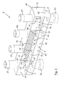
- FIG. 1 The drawing shows a heating circuit manifold 1 in a first embodiment, with open front side shown, in a perspective view obliquely from the left front.
- the heating circuit manifold 1 has a horizontally oriented, elongated, flat parallelepiped housing 10, which is represented by a bottom wall 11, a top wall 12, a front wall 13, otherwise broken away here, only a small portion at the top left, a rear wall 14 and two end walls 15 and 15 'is formed.
- the individual walls are made of sheet steel, for example, and are tightly welded together.
- a partition wall 16 is arranged, which extends parallel to the bottom wall 11 and the top wall 12 between them.
- the space above the dividing wall 16 is subdivided into three chambers by two bulkhead walls 19, 19 'extending parallel to the end walls 15, 15', namely from right to left a feed chamber 2, an intermediate chamber 4 and a return chamber 3.
- a switch chamber 5 of the heating circuit manifold is below the dividing wall 16 in the housing 10.
- an intermediate plate 17, here in the form of a perforated plate, is arranged parallel to and at a distance from the dividing wall 16, dividing the intermediate chamber 4 into an upper chamber part 40 and a lower chamber part 40 '.
- the partition 16 has in the present embodiment a total of four apertures 61, 62, 70 and 70 '.
- the opening 61 connects the switch chamber 5 near the end wall 15 with the flow chamber 2.
- the opening 62 connects the return chamber 3 near the other end wall 15 'with the switch chamber 5.
- the two openings 70 and 70' connect the intermediate chamber 4 and the switch chamber 5 with each other and are spaced apart in the longitudinal direction of the housing 10.
- Each opening 70, 70 ' is assigned on the underside each one arranged in the switch chamber 5 pipe socket 71, 71'.
- the in FIG. 1 left pipe socket 71 ' has on its outward, that is, the end wall 15' facing side an opening 72 'to the switch chamber 5; in a corresponding, game-symmetrical arrangement of the pipe socket 71 has on its side facing the other end wall 15 an opening 72 'which in FIG. 1 is not visible.
- two flow guide walls 18, 18 'aligned transversely to the turnout chamber 5 are provided in the embodiment shown, each extending from the underside of the dividing wall 16 downwards over part of the height of the turnout chamber 5.
- one or both flow guide walls 18, 18 ' may also be arranged on the upper side of the bottom wall 11.
- a first heating circuit flow connection 21 which is fluidly connected to the flow chamber 2
- a first heating circuit return connection 42 which is fluidly connected to the intermediate chamber 4
- a second Heating circuit flow connection 41 which is fluidly connected to the intermediate chamber 4
- a second heating circuit return connection 32 which is fluidly connected to the return chamber 3.
- connections 21, 32, 41 and 42 further piping can be connected, which connect the heating circuit manifold 1 with heaters, which are not shown here.
- connections 51, 52 can be connected further pipelines that connect the heating circuit 1 with one or more boilers.
- a sleeve 80 is grown, which serves to receive a temperature sensor, which detects the flow temperature of the inflowing into the heating circuit manifold 1 heating medium.
- the boiler inlet port 51, the opening 61 and the heating circuit flow connection 21 are arranged in alignment with each other; Similarly, the boiler return port 52, the aperture 62 and the heating circuit return port 32 are aligned with each other. Also, the pipe socket 71, the aperture 70 and the heating circuit return port 42 have here aligned alignment, as well as the pipe socket 71 ', the opening 70' and the heating circuit flow connection 41st
- FIG. 2 shows the heating circuit manifold 1 from FIG. 1 , again with open front, in a second perspective view obliquely from the right front. Unlike the FIG. 1 is now visible on the right pipe socket 71 whose facing the right end wall 15 opening 72. Regarding the further in FIG. 2 visible individual parts of the heating circuit 1 and the reference numerals drawn is to the previous description of FIG. 1 directed.
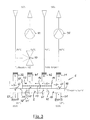
- FIG. 3 the drawing shows the heating circuit manifold 1 from the FIGS. 1 and 2 in a first exemplary operating state, in a schematic representation.
- heated heating medium such as water flows at a temperature of here, for example, about 60 ° C in the heating circuit manifold 1 and through the turnout chamber 5 and the aperture 61 into the flow chamber 2 a.
- a first heating circuit is connected, for example, supplies radiators, which require a relatively high flow temperature of, for example, about 60 ° C for their operation.
- a circulation pump 91 the heating medium from the flow chamber 2 of the heating circuit manifold 1 through the heating circuit flow connection 21 through the first heating circuit is supplied.
- the heating medium flows with reduced Temperature from here, for example, about 45 ° C through the first heating circuit return connection 42 into the intermediate chamber 4 of the heating circuit manifold.
- the heating medium flows to the second heating circuit flow connection 41 and is conveyed from there by means of a second circulation pump 92 through a second heating circuit, which supplies, for example, a floor heating system here.
- the intermediate plate 17 forms a flow resistance for the heating medium, which ensures that in the intermediate chamber 4, the heating medium flows preferably from Schunikonnean gleich 42 to Schunikdorfan gleich 41 and not the way through the intermediate plate 17, the pipe socket 71 'and the switch chamber 5 to the boiler return port 52nd takes.
- the underfloor heating requires a lower flow temperature, for example, of about 45 ° C, which corresponds almost exactly to the return temperature of the first heating circuit.
- the now again cooled heating medium flows with a further reduced temperature, here for example of about 35 ° C, through the second return port 32 in the return chamber 3.
- the heating medium flows through the opening 62 and the switch chamber 5 in the Schukessel Weglaufan gleich 52 and through this to the boiler not shown here for reheating, in order then again to be supplied through the boiler flow connection 51 to the heating circuit manifold 1.
- both heating circuits have the same volume flow requirement of heating medium, so that balancing flows between the different circuits are not required. Rather, here the two heating circuits are flowed through in succession in a pure series connection of the heating medium.
- the thermal energy contained in the heating medium is optimally utilized in this way and the heating medium flows back into the return chamber 3 with an advantageously low temperature.
- FIG. 4 shows the heating circuit manifold 1 in a second exemplary operating state, in the same schematic representation as in FIG. 3 .
- the operating state of the first heating circuit for the radiator has about twice as large volume flow demand of heating medium as the second heating circuit with the floor heating.
- the volume flows through the two heating circuits are therefore no longer the same size.
- the heating medium flowing back from the second heating circuit for the underfloor heating flows through the heating circuit return connection 32 first into the return chamber 3 and from there through the opening 62 into the switch chamber 5, where the two partial volume flows reunite to form the total volume flow and together through the boiler return connection 52 are fed to the boiler for reheating.
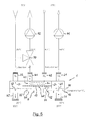
- FIG. 5 shows the heating circuit manifold 1 in a third exemplary operating state, in the same schematic representation as in the Figures 3 and 4 , It is characteristic of this third operating state that now the first heating circuit with the radiators requires a lower volume flow of heating medium than the second heating circuit with the underfloor heating.
- heated heating medium flowing from the boiler flows through the boiler feed connection 51 into the switch chamber 5.
- the volume flow of the heating medium is divided into two partial volume flows.
- a first partial volume flow flows through the opening 61 and the flow chamber 2 via the first heating circuit flow connection 21 into the first heating circuit and is conveyed by the pump 91 through the latter.
- a second partial volume flow of the heating medium flows first within the turnout chamber 5 in the direction of the pipe stub 71 and through the opening 72 into this and then up into the lower chamber part 40 'of the intermediate chamber 4. Further, this partial volume flow flows through the as a perforated plate executed intermediate plate 17 in the upper chamber portion 40 of the intermediate chamber 4 and unites there with the partial volume flow, which also flows from the first heating circuit through the heating circuit return port 42 in the upper chamber portion 40 of the intermediate chamber 4. Combined then form the two part-volume flows the full volume flow, which meets the higher demand of the second heating circuit of heating medium here.
- This full volume flow of heating medium flows through the heating circuit flow connection 41 and the mixing valve 90, while being conveyed by the pump 92 through the second heating circuit.
- the mixing valve 90 By means of the mixing valve 90, the flow temperature of the second heating circuit in the flow direction behind the mixing valve 90 to a desired value, here about 45 ° C, adjusted to avoid too high flow temperature in the second heating circuit by supplying coming directly from the boiler heating medium. After flowing through the second heating circuit, the entire volume flow of the heating medium flows through the heating circuit return port 32 in the return chamber 3 and from there through the opening 62 and the left end of the turnout chamber 5 in the boiler return port 52 and then to reheat to the boiler.
- a desired value here about 45 ° C
- FIG. 6 shows the heating circuit manifold 1 in a fourth exemplary operating state, again in the schematic representation of FIGS. 3 to 5 .
- Characteristic of this fourth operating state is that now both heating circuits have no need for heating medium, because just no heating power is needed.
- the heated heating medium flows through the boiler inlet connection 51 into the switch chamber 5.
- the heating medium does not substantially leave the switch chamber 5, but flows through it over its entire length at the two pipe connections 71 and 71 'and at the flow guide walls
- a certain side stream of heating medium can parallel through the first pipe socket 71, the intermediate chamber 4 and the second pipe socket 71 'to flow to the left end of the switch chamber 5, then by the local boiler return port 52 directly to Return boiler.
- a clocking of the boiler is avoided and that shortcoming of a low water content of today's modern boiler compensated.
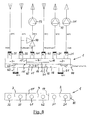
- FIG. 7 The drawing shows the heating circuit manifold 1 in a second embodiment, at the top in the figure in a schematic view and at the bottom in the figure in a schematic plan view.
- the heating circuit distributor 1 is after FIG. 7 designed for three heating circuits, so has at its top a total of three Banknikvorlaufan Why 21, 41 and accordingly also three Banknikschreiban say 32, 42.
- a boiler inlet port 51 and a boiler return port 52 are also arranged here on the underside of the housing 10 of the heating manifold 1.
- the internal structure of the heating circuit manifold 1 according to FIG. 7 corresponds to the example described above.
- the terminals 21, 32, 41, 42 are mounted at equal intervals on the upper side of the heating circuit 1. Accordingly, the two bulkhead walls 19 and 19 ', on the one hand the flow chamber 2 and the intermediate chamber 4 and on the other hand, the intermediate chamber 4 and the return chamber 3 separate from each other, arranged offset from the first embodiment.
- the first bulkhead 19 now lies between the left heating circuit supply connection 21 and the right heating circuit return connection 42.
- the two first heating circuits for the radiator are flowed through in parallel. These two heating circuits form a series circuit with the third heating circuit for underfloor heating. If the two first heating circuits for the radiator have a different volume flow requirement of heating medium, this can be adjusted by appropriate control of the respective associated circulation pump 91 and 92. If the two first heating circuits for the radiators in the sum should have a different demand for heating medium flow rate than the third heating circuit for underfloor heating, then takes place via the hydraulic switch function of the heating circuit 1 by means of a balance volume flow of heating medium through the switch chamber 5 a corresponding hydraulic compensation, as already described above, even if all heating circuits need no heating medium.
- FIG. 8 shows the heating circuit distributor 1 in a third embodiment, again at the top in the figure in a schematic view and at the bottom in the figure in a schematic plan view.
- the heating circuit manifold 1 is designed for the connection of a first heating circuit for radiators, a second heating circuit for underfloor heating and, new, a third heating circuit for a Water heaters.
- the internal structure of the heating circuit distributor 1 with the housing 10 and the chambers 2, 3, 4 and 5 provided therein corresponds in principle to the previous exemplary embodiments. Different is the arrangement of the bulkhead walls 19 and 19 ', because the in FIG. 8 left bulkhead 19 'is compared to for example after FIG.
- the heating circuit 1 In normal operation of the heating circuit 1 flows, for example heated to about 60 ° C heating medium again coming from a boiler through the boiler flow connection 51 into the switch chamber 5 and from this immediately further through the opening 61 in the flow chamber 2. There, the volume flow of the heating medium in two partial volume flows, which flow through the two Schunikvorlaufan Why 21 in two different heating circuits, namely a heating circuit with radiators and a heating circuit with a water heater. The promotion of the heating medium through these two heating circuits is again by means of a respective circulation pump 91 and 92.
- the heating medium flows, cooled to a temperature of, for example, about 45 ° C, through the Schunikmaschinemaschinean gleich 42 into the intermediate chamber 4.
- the heating medium of its flow temperature is further cooled than in the heating circuit with the radiators, here, for example a temperature of about 35 ° C, and is therefore not supplied to the intermediate chamber 4 via the heating circuit return connection 32, but directly to the return chamber 3.
- the heating circuit for underfloor heating is supplied via the heating circuit flow connection 41 with heating medium from the intermediate chamber 4, wherein the circulation is effected here by means of the pump 93.
- the mixing valve 90 the flow of the underfloor heating medium from the return can be mixed if necessary.
- the heating medium returning from this heating circuit also passes through the second heating circuit return connection 32 into the return chamber 3. There, the partial volume flows of the heating medium are combined again to the full volume flow and this is then through the opening 62, through the left end the switch chamber 5 and the boiler return port 52 are fed to the boiler for reheating.
- the volume flow differences by means of the hydraulic function of the switch chamber 5 of the heating circuit 1 are compensated in the case of varying or fluctuating volume flow demand of heating medium in the various heating circuits by compensating volume flows of the heating medium are passed through the switch chamber 5. This also applies here in the extreme case that none of the heating circuits has a need for heating medium.
- heating circuit 10 casing 11 bottom wall 12 top wall 13 front wall 14 rear wall 15, 15 ' end walls 16 partition wall 17 intermediate plate 18, 18 ' flow guide 19, 19 ' bulkheads 2 lead chamber 21 Heating circuit supply connection to 2 3 Return chamber 32 Heating circuit return connection to 3 4 intermediate chamber 40, 40 ' Upper, lower chamber part of 4 41 Heating circuit flow connection to 4 42 Heating circuit return connection to 4 5 soft chamber 51 Boiler supply connection to 5 52 Boiler return connection to 5 61 Breakthrough in 16 between 5 and 2 62 Breakthrough in 16 between 3 and 5 70, 70 ' Breakthroughs in 16 between 5 and 4 71, 71 ' pipe socket 72, 72 ' Opening in 71, 71 ' 80 Temperature sensor sleeve 90 mixing valve 91, 92, 93 pump
Landscapes
- Engineering & Computer Science (AREA)
- Physics & Mathematics (AREA)
- Thermal Sciences (AREA)
- Chemical & Material Sciences (AREA)
- Combustion & Propulsion (AREA)
- Mechanical Engineering (AREA)
- General Engineering & Computer Science (AREA)
- Steam Or Hot-Water Central Heating Systems (AREA)
Abstract
Description
Die vorliegende Erfindung betrifft einen Heizkreisverteiler mit integrierter hydraulischer Weiche, mit einem länglichen, im Betrieb horizontal angeordneten Gehäuse, in dem eine Vorlaufkammer hoher Heizmediumtemperatur und eine Rücklaufkammer niedriger Heizmediumtemperatur und eine diese beiden Kammern strömungsmäßig verbindende Weichenkammer angeordnet sind, wobei an dem Gehäuse einerseits mehrere Heizkreisvorlaufanschlüsse und mehrere Heizkreisrücklaufanschlüsse und andererseits je ein Heizkesselvorlaufanschluss und Heizkesselrücklaufanschluss vorgesehen sind, wobei der Heizkesselvorlaufanschluss und der Heizkesselrücklaufanschluss in die Weichenkammer münden und wobei die Weichenkammer an zwei horizontal voneinander beabstandeten Stellen einerseits mit der Vorlaufkammer und andererseits mit der Rücklaufkammer strömungsmäßig verbunden ist.The present invention relates to a heating circuit manifold with integrated hydraulic switch, with an elongated, horizontally arranged in operation housing in which a flow chamber high Heizmediumtemperatur and a return chamber low heating medium temperature and these two chambers are fluidly connected switch chamber are arranged, wherein on the housing on the one hand several Heizkreisvorlaufanschlüsse and a plurality of Heizkreisrücklaufanschlüsse and on the other hand each a boiler supply connection and boiler return connection are provided, wherein the boiler flow connection and the boiler return port open into the switch chamber and wherein the switch chamber is connected at two horizontally spaced locations on the one hand to the flow chamber and on the other hand to the return chamber fluidly connected.
Ein Heizkreisverteiler der vorstehend angegebenen Art ist aus
Als nachteilig wird bei diesem bekannten Verteiler angesehen, dass er nur für die Versorgung mehrerer Heizkreise mit untereinander gleicher Heizkreisvorlauftemperatur gut geeignet ist, weil alle Heizkreise gemeinsam aus der Vorlaufkammer versorgt werden. Bei modernen Heizungsanlagen besteht aber zunehmend ein Bedarf, zwei oder mehr Heizkreise mit unterschiedlicher Heizkreisvorlauftemperatur und/oder unterschiedlicher Heizkreisrücklauftemperatur bei wirtschaftlichem Betrieb zu versorgen.A disadvantage is considered in this known distributor, that it is well suited only for the supply of several heating circuits with mutually equal heating circuit flow temperature, because all heating circuits are supplied together from the flow chamber. In modern heating systems, however, there is an increasing need for two or more heating circuits with different heating circuit flow temperature and / or supply different heating circuit return temperature during economical operation.
Aus
Ein derartiger Verteiler vermeidet zwar die Nachteile des erstgenannten Verteilers nach dem Stand der Technik, ist jedoch relativ aufwendig in seiner Konstruktion und benötigt einen relativ großen Bauraum, was seinen Einsatz erst bei Heizungsanlagen mit mehr als zwei oder drei Heizkreisen mit unterschiedlicher Heizkreisvorlauftemperatur und/oder mit mehreren Wärmequellen unterschiedlicher Vorlauftemperatur technisch und wirtschaftlich sinnvoll macht.Although such a distributor avoids the disadvantages of the former distributor according to the prior art, but is relatively expensive in its construction and requires a relatively large amount of space, which its use only in heating systems with more than two or three heating circuits with different heating circuit flow temperature and / or with several heat sources different flow temperature technically and economically makes sense.
Während die beiden in den vorgenannten Dokumenten zum Stand der Technik vorgestellten Lösungen ohne größeren Regelungsaufwand auskommen, sind aus der Praxis auch Lösungen für Heizungsanlagen, bei denen Verbraucherkreise mit unterschiedlichen Temperaturniveaus angeschlossen sind, bekannt, die für einen optimalen Betrieb dieser Anlagen einen hohen elektronischen Aufwand hinsichtlich Regelung und Steuerung einsetzen. Dies erfordert z.B. elektrisch verstellbare Ventile und Mischer, in ihrer Drehzahl regelbare Pumpen, diverse Temperaturfühler und eine übergeordnete elektronische Steuereinheit, was die Anlagen aufwendig und teuer macht.While the two presented in the aforementioned documents to the prior art solutions get along without major regulatory effort, solutions for heating systems in which consumer circuits are connected with different temperature levels, known from practice, for optimum operation of these systems a high electronic effort in terms Use regulation and control. This requires, for example, electrically adjustable valves and mixers, variable speed pumps, various temperature sensors and a higher-level electronic control unit, which makes the equipment complex and expensive.
Es stellt sich daher die Aufgabe, einen Heizkreisverteiler der eingangs genannten Art zu schaffen, der die vorstehend dargelegten Nachteile vermeidet und der bei technisch einfacher, kompakter Bauweise die Versorgung von wenigstens zwei Heizkreisen mit Heizmedium mit zwei unterschiedlichen Heizkreisvorlauftemperaturen ermöglicht.It is therefore an object to provide a heating circuit distributor of the type mentioned above, which avoids the disadvantages set out above and allows the supply of at least two heating circuits with heating medium with two different heating circuit flow temperatures in a technically simple, compact design.
Die Lösung dieser Aufgabe gelingt erfindungsgemäß mit einem Heizkreisverteiler der eingangs genannten Art, der dadurch gekennzeichnet ist,
- dass zusätzlich zu der Vorlaufkammer hoher Heizmediumtemperatur und der Rücklaufkammer niedriger Heizmediumtemperatur eine Zwischenkammer mittlerer Heizmediumtemperatur im Gehäuse angeordnet ist,
- dass mit der Vorlaufkammer hoher Heizmediumtemperatur mindestens ein Heizkreisvorlaufanschluss eines Heizkreises mit hoher Heizmediumvorlauftemperatur verbunden ist,
- dass mit der Zwischenkammer mindestens ein Heizkreisrücklaufanschluss eines Heizkreises mit mittlerer Heizmediumrücklauftemperatur und mindestens ein Heizkreisvorlaufanschluss eines Heizkreises mit mittlerer Heizmediumvorlauftemperatur verbunden sind,
- dass mit der Rücklaufkammer niedriger Heizmediumtemperatur mindestens ein Heizkreisrücklaufanschluss eines Heizkreises mit niedriger Heizmediumrücklauftemperatur verbunden ist und
- dass die Zwischenkammer und die Weichenkammer über mindestens eine Verbindung innerhalb des Gehäuses strömungsmäßig miteinander verbunden sind.
- an intermediate chamber of medium heating medium temperature is arranged in the housing in addition to the flow chamber of high heating medium temperature and the return chamber of low heating medium temperature,
- in that at least one heating circuit flow connection of a heating circuit having a high heating medium flow temperature is connected to the flow chamber of high heating medium temperature,
- in that at least one heating circuit return connection of a heating circuit having an average heating medium return temperature and at least one heating circuit supply connection of a heating circuit having an average heating medium supply temperature are connected to the intermediate chamber,
- that at least one heating circuit return connection of a heating circuit with a low heating medium return temperature is connected to the return chamber of low heating medium temperature, and
- in that the intermediate chamber and the switch chamber are fluidly connected to one another via at least one connection within the housing.
Mit der Erfindung wird ein Heizkreisverteiler geschaffen, mit dem wenigstens zwei Heizkreise mit Heizmedium zweier unterschiedlicher Temperaturen versorgt werden können und mit dem gleichzeitig über die integrierte hydraulische Weiche alle gegebenenfalls im Betrieb auftretenden Volumenstromdifferenzen sowohl zwischen den verschiedenen Heizkreisen als auch zwischen dem Kesselkreis und den Heizkreisen ausgeglichen werden können. Ein wirtschaftlich optimaler Betrieb ergibt sich dann, wenn die Rücklauftemperatur des Heizkreises mit der höheren Heizmediumtemperatur im Bereich der Vorlauftemperatur des Heizkreises mit der niedrigeren Heizmediumtemperatur liegt; die Heizkreise können dann strömungsmäßig in Reihe geschaltet von dem Heizmedium nacheinander durchströmt werden, bevor das Heizmedium dem Heizkessel zur erneuten Erhitzung wieder zugeführt wird. Hierbei wird die im Heizmedium enthaltende Wärmeenergie optimal genutzt und dem Heizkessel wird das Heizmedium mit der niedrigsten möglichen Temperatur zu erneuten Erhitzung zugeführt, was Vorteile insbesondere beim Einsatz eines Brennwertkesseln als Heizkessel mit sich bringt. Dabei besitzt der Heizkreisverteiler nur eine geringe Baugröße, die praktisch nicht größer ist als bei den bekannten Verteilern gemäß dem oben an erster Stelle genannten Stand der Technik. Gegenüber Verteilern nach dem oben an zweiter Stelle genannten Stand der Technik besitzt der erfindungsgemäßen Heizkreisverteiler den Vorteil einer technisch einfacheren Konstruktion und wesentlich kompakteren Bauweise. Im Vergleich zu dem oben an dritter Stelle genannten Stand der Technik bietet der erfindungsgemäße Heizkreisverteiler eine kostengünstige Lösung zur Versorgung von Heizungsanlagen, bei denen die Verbraucherkreise mit unterschiedlichen Temperaturniveaus arbeiten. Dabei kann vorteilhaft auf aufwendige Komponenten und Elemente mit einem größeren Regelungsaufwand zur Steuerung und Regelung verzichtet werden.With the invention, a heating circuit manifold is provided with which at least two heating circuits can be supplied with heating medium of two different temperatures and compensated with the simultaneously occurring via the integrated hydraulic switch all possibly occurring during operation volume flow differences both between the various heating circuits and between the boiler circuit and the heating circuits can be. An economically optimal operation results when the return temperature of the heating circuit with the higher heating medium temperature is in the range of the flow temperature of the heating circuit with the lower heating medium temperature; the heating circuits can then be flow-connected in series through which the heating medium flows successively, before the heating medium is returned to the boiler for renewed heating. Here, the heat energy contained in the heating medium is used optimally and the boiler the heating medium is supplied to the lowest possible temperature for reheating, which brings advantages in particular when using a condensing boilers as a boiler with it. In this case, the Heizkreisverteiler has only a small size, which is practically no larger than in the known distributors according to the above-mentioned in the first place of the prior art. Compared to distributors according to the above second prior art, the heating circuit distributor according to the invention has the advantage of a technically simpler design and much more compact design. In comparison with the prior art mentioned above in the third place, the heating circuit distributor according to the invention offers a cost-effective solution for supplying heating systems in which the consumer circuits operate at different temperature levels. It can be advantageously dispensed with complex components and elements with a greater regulatory effort for control and regulation.
Grundsätzlich können die verschiedenen Kammern des Heizkreisverteilers an beliebigen Stellen im Gehäuse untergebracht sein. Aus Gründen einer übersichtlichen und günstigen Strömungsführung und Anschlussanordnung ist aber erfindungsgemäß bevorzugt vorgesehen, dass die Vorlaufkammer, die Rücklaufkammer und die Zwischenkammer in einem oberen Teil des Gehäuses angeordnet sind und dass die Weichenkammer darunter in einem unteren Teil des Gehäuses angeordnet ist. Die Vorlaufkammer, die Rücklaufkammer und die Zwischenkammer können in einer Höhe angeordnet sein, so dass dann auch die verschiedenen Heizkreisvorlaufanschlüsse und -rücklaufanschlüsse entsprechend auf einer Höhe angeordnet sein können. Die mit der Weichenkammer verbundenen Kesselvorlauf- und Kesselrücklaufanschlüsse können entfernt von den Heizkreisvorlauf- und Heizkreisrücklaufanschlüssen am Gehäuse angeordnet sein. Insgesamt ergibt dies eine übersichtliche, Anschlussfehler vermeidende Anschlussanordnung für den Heizkreisverteiler.In principle, the various chambers of the heating circuit distributor can be accommodated anywhere in the housing. For reasons of a clear and favorable flow guidance and connection arrangement, however, according to the invention it is preferably provided that the flow chamber, the return chamber and the intermediate chamber are arranged in an upper part of the housing and that the switch chamber is arranged underneath in a lower part of the housing. The flow chamber, the return chamber and the intermediate chamber may be arranged at a height, so that then the various heating circuit flow connections and return connections can be arranged correspondingly at a height. The boiler feed and boiler return ports connected to the switch chamber may be remote from the heater circuit supply and return circuits on the housing. Overall, this results in a clear, connection error-avoiding connection arrangement for the heating circuit manifold.
Zwecks einer einfachen technischen Konstruktion und günstigen Herstellbarkeit des Heizkreisverteilers ist bevorzugt vorgesehen, dass das Gehäuse eine Trennwand aufweist, welche die Vorlaufkammer, die Rücklaufkammer und die Zwischenkammer unterseitig und die Weichenkammer oberseitig begrenzt und welche mindestens drei Durchbrechungen zur Herstellung der Strömungsverbindungen zwischen der Weichenkammer einerseits und der Vorlaufkammer, der Rücklaufkammer und der Zwischenkammer andererseits aufweist. Trotz ihrer diversen Funktionen ist die Trennwand hier ein einfaches und kostengünstiges Bauteil.For the purpose of a simple technical construction and cheap manufacturability of Heizkreisverteilers is preferably provided that the housing has a partition, the upper side delimits the flow chamber, the return chamber and the intermediate chamber and the upper chamber and which at least three openings for producing the flow connections between the switch chamber on the one hand and the flow chamber, the return chamber and the intermediate chamber on the other hand. Despite its various functions, the dividing wall here is a simple and cost-effective component.
Weiter schlägt die Erfindung vor, dass in Längsrichtung des Gehäuses gesehen die Vorlaufkammer und die Rücklaufkammer stirnendseitig im Gehäuse angeordnet sind und dass sich die Zwischenkammer über den verbleibenden mittleren Teil der Länge des Gehäuses zwischen der Vorlaufkammer und der Rücklaufkammer erstreckt. Mit dieser Anordnung der genannten Kammern im Gehäuse relativ zueinander wird eine übersichtliche Zuordnung der verschiedenen Anschlüsse dieser Kammern ermöglicht. Zusätzlich werden Wärmeverluste innerhalb des Verteilers gering gehalten, weil keine besonders großen Temperaturdifferenzen zwischen den einander benachbarten Kammern auftreten.Further, the invention proposes that seen in the longitudinal direction of the housing, the flow chamber and the return chamber are arranged end face in the housing and that the intermediate chamber extends over the remaining central part of the length of the housing between the flow chamber and the return chamber. With this arrangement of said chambers in the housing relative to each other a clear assignment of the various ports of these chambers is made possible. In addition, heat losses within the distributor are kept low because no particularly large temperature differences occur between the adjacent chambers.
Die absoluten Kammergrößen und das Verhältnis der Kammergrößen relativ zueinander richtet sich nach dem Bedarf der zugehörigen Heizungsanlage, insbesondere danach, wie viele Abnehmer- oder Heizkreise in den unterschiedlichen Temperaturniveaus an der jeweiligen Kammer angebunden sind und welcher Volumenstrom an Heizmedium von den Heizkreisen benötigt wird.The absolute chamber sizes and the ratio of the chamber sizes relative to each other depends on the needs of the associated heating system, in particular how many customer or heating circuits are connected in the different temperature levels at the respective chamber and what volume flow of heating medium is required by the heating circuits.
Um eine günstige, übersichtliche und platzsparende Verrohrung des erfindungsgemäßen Heizkreisverteiler zu ermöglichen, sind bevorzugt die Heizkreisvorlaufanschlüsse und Heizkreisrücklaufanschlüsse oberseitig und der Kesselvorlaufanschluss und der Kesselrücklaufanschluss unterseitig an dem Gehäuse angeordnet. Alle zum Anschluss des Heizkreisverteilers nötigen Rohrleitungen können somit vorteilhaft in einer Ebene angeordnet werden.In order to allow a cheap, clear and space-saving piping of the heating circuit manifold according to the invention, preferably the heating circuit flow connections and Heizkreisrücklaufanschlüsse are on the upper side and the boiler flow connection and the boiler return port on the underside of the housing. All necessary for connection of the heating circuit manifold pipes can thus be arranged advantageously in a plane.
Im normalen Betrieb des Heizkreisverteilers, in dem keine Ausgleichsströmungen über die hydraulische Weiche fließen, sollen die Heizmediumströme möglichst verlustarm durch den Heizkreisverteiler strömen können. Zu diesem Zweck wird vorgeschlagen, dass der Kesselvorlaufanschluss, der mindestens eine mit der Vorlaufkammer verbundene Heizkreisvorlaufanschluss und die zugehörige Durchbrechung in der Trennwand miteinander fluchtend angeordnet sind und dass der Kesselrücklaufanschluss, der mindestens eine mit der Rücklaufkammer verbundene Heizkreisrücklaufanschluss und die zugehörige Durchbrechung in der Trennwand miteinander fluchtend angeordnet sind. Strömungsumlenkungen im Gehäuse des Verteilers, die zu einem erhöhten Strömungswiderstand führen würden, werden so vermieden. Zur Erzielung günstiger Strömungsverhältnisse zwischen der Weichenkammer und der Zwischenkammer im Falle von Ausgleichsströmungen ist bevorzugt vorgesehen, dass die Zwischenkammer und die Weichenkammer über zwei in Längsrichtung des Gehäuses voneinander beabstandete Durchbrechungen in der Trennwand miteinander strömungsmäßig verbunden sind. Aufgrund des Abstandes der beiden Durchbrechungen liegt die eine Durchbrechung näher zum Kesselvorlaufanschluss und die andere Durchbrechung näher zum Kesselrücklaufanschluss, so dass durch die erstgenannte Durchbrechung im Wesentlichen Heizmedium vom Kesselvorlaufanschluss aus der Weichenkammer in die Zwischenkammer strömen kann, während durch die andere Durchbrechung im Wesentlichen Heizmedium aus der Zwischenkammer in die Weichenkammer und dann zum Kesselrücklaufanschluss strömen kann.During normal operation of the heating circuit distributor, in which no compensating flows flow via the hydraulic separator, the heating medium flows should be able to flow through the heating circuit distributor with as little loss as possible. For this purpose, it is proposed that the boiler feed connection, the at least one associated with the flow chamber Heizkreisvorlaufanschluss and the associated aperture in the partition are aligned with each other and that the boiler return port, the at least one connected to the return chamber Heizkreisrücklaufanschluss and the associated opening in the partition with each other are arranged in alignment. Flow deflections in the housing of the distributor, which would lead to increased flow resistance, are thus avoided. In order to achieve favorable flow conditions between the switch chamber and the intermediate chamber in the case of compensating flows, it is preferably provided that the intermediate chamber and the switch chamber are fluidly connected to one another via two openings in the partition which are spaced apart from one another in the longitudinal direction of the housing. Due to the distance between the two openings, the one opening is closer to the boiler supply connection and the other opening closer to the boiler return connection, so that can flow through the first-mentioned opening substantially heating medium from the boiler supply connection from the switch chamber in the intermediate chamber, while through the other opening substantially heating medium the intermediate chamber can flow into the switch chamber and then to the boiler return port.
Eine weitere Maßnahme zur Erzielung günstiger Strömungsverhältnisse besteht darin, dass vorzugsweise der mit der Zwischenkammer verbundene mindestens eine Heizkreisrücklaufanschluss und mindestens eine Heizkreisvorlaufanschluss jeweils fluchtend mit einer der Durchbrechungen in der Trennwand zwischen Weichenkammer und Zwischenkammer angeordnet sind.Another measure for achieving favorable flow conditions is that preferably the at least one heating circuit return connection connected to the intermediate chamber and at least one heating circuit supply connection are each arranged in alignment with one of the openings in the partition between the switch chamber and the intermediate chamber.
Um eine unerwünschte Kurzschlussströmung vom Kesselvorlaufanschluss durch die Weichenkammer zum Kesselrücklaufanschluss zu vermeiden oder zumindest auf ein nicht störendes Maß zu begrenzen, ist erfindungsgemäß vorgesehen, dass den beiden Durchbrechungen jeweils ein sich über die Höhe der Weichenkammer erstreckender Rohrstutzen mit wenigstens einer seitlichen Öffnung zugeordnet ist, wobei die Öffnung jeweils zum nächstgelegenen Kesselanschluss weist. Zweckmäßig ist dabei der Außendurchmesser der Rohrstutzen so gewählt, dass sie den größten Teil des Querschnitts der Weichenkammer einnehmen, jedoch noch einen ausreichenden Querschnitt zur Ermöglichung der bedarfsweisen Ausgleichsströmungen freilassen. Für die Ausgleichsströmungen reicht in der Praxis ein verbleibender Querschnitt von etwa 10 bis 20% des gesamten Querschnitts der Weichenkammer aus. Die Rohrstutzen können so einen relativ großen Innendurchmesser aufweisen, was wiederum vorteilhaft für die bedarfsweisen Ausgleichsströmungen zwischen der Weichenkammer und der Zwischenkammer ist. Ein hier gewünschter Strömungswiderstand kann durch geeignete Wahl der Größe der seitlichen Öffnung der Rohrstutzen passend eingestellt werden.In order to avoid an undesirable short-circuit flow from the boiler flow connection through the switch chamber to the boiler return connection or at least to limit a non-interfering measure, the invention provides that the two openings each one is assigned over the height of the switch chamber pipe socket with at least one lateral opening, wherein the opening points to the nearest boiler connection. Appropriately, the outer diameter of the pipe socket is chosen so that they occupy most of the cross section of the switch chamber, but still leave a sufficient cross-section to enable the demand-compensating flows. In practice, a residual cross section of about 10 to 20% of the total cross section of the switch chamber is sufficient for the compensation flows. The pipe socket can thus have a relatively large inner diameter, which in turn is advantageous for the demand-compensating flows between the switch chamber and the intermediate chamber. A desired flow resistance can be suitably adjusted by a suitable choice of the size of the lateral opening of the pipe socket.
Das durch den zugehörigen Heizkreisrücklaufanschluss in die Zwischenkammer einströmende Heizmedium aus dem Heizkreis mit der höheren Heizmediumtemperatur soll bevorzugt in den ebenfalls der Zwischenkammer zugeordneten Heizkreisvorlaufanschluss für den Heizkreis mit der niedrigen Heizmediumtemperatur zuströmen. Um diese gewünschte Strömung zu unterstützen, ist gemäß einer weiteren Ausgestaltung des Heizkreisverteilers vorgesehen, dass in der Zwischenkammer eine diese in einen oberen und unteren Kammerteil unterteilende, für das Heizmedium durchlässige und für dieses einen Strömungswiderstand darstellende Zwischenplatte angeordnet ist. Hiermit wird für die vorerwähnte gewünschte Strömung ein niedriger Strömungswiderstand erreicht, während für bedarfsweise auftretende Ausgleichsströmungen das Heizmedium durch die einen Strömungswiderstand darstellende Zwischenplatte strömen muss.The heating medium flowing in through the associated heating circuit return connection into the intermediate chamber from the heating circuit with the higher heating medium temperature should preferably flow into the heating circuit supply connection for the heating circuit with the low heating medium temperature likewise assigned to the intermediate chamber. In order to support this desired flow, according to a further embodiment of the heating circuit distributor it is provided that in the intermediate chamber there is arranged an intermediate plate which subdivides this into an upper and lower chamber part, is permeable to the heating medium and represents a flow resistance. Hereby, a low flow resistance is achieved for the aforementioned desired flow, while for necessary occurring compensating flows the heating medium must flow through the flow resistance performing intermediate plate.
Zwecks einfacher Fertigung ist die Zwischenplatte bevorzugt durch ein Lochblech gebildet. Ein gewünschter Strömungswiderstand des Lochblechs kann einfach durch die Dichte und/oder die freie Querschnittsgröße der Löcher festgelegt werden.For ease of manufacture, the intermediate plate is preferably formed by a perforated plate. A desired flow resistance of the perforated plate can be determined simply by the density and / or the free cross-sectional size of the holes.
Eine zusätzliche oder alternative technische Maßnahme zur Vermeidung oder Begrenzung von Kurzschlussströmungen zwischen dem Heizkesselvorlaufanschluss und dem Heizkesselrücklaufanschluss durch die Weichenkammer besteht darin, dass vorzugsweise von der Trennwand unterseitig und/oder von der Bodenwand oberseitig eine oder mehrere quer angeordnete Strömungsleitwände ausgehen, die sich über einen Teil der Höhe der Weichenkammer erstrecken. Der freie Strömungsquerschnitt der Weichenkammer kann so an einer oder mehreren Stellen auf ein gewünschtes Maß reduziert werden.An additional or alternative technical measure for avoiding or limiting short circuit flows between the boiler flow connection and the boiler return connection through the switch chamber is that preferably one or more transversely arranged flow guide walls project from the partition wall on the underside and / or from the bottom wall on one side extend the height of the switch chamber. The free flow cross section of the switch chamber can thus be reduced to one or more locations to a desired level.
Bevorzugt ist dabei weiter vorgesehen, dass sich die Strömungsleitwände maximal über die halbe Höhe der Weichenkammer erstrecken und in Längsrichtung der Weichenkammer gesehen voneinander beabstandet jeweils innen vom Heizkesselvorlaufanschluss bzw. vom Heizkesselrücklaufanschluss liegen. In dieser Anordnung schirmen die Strömungsleitwände vorteilhaft die Durchbrechung(en) zwischen der Weichenkammer und der Zwischenkammer von der Heizmediumströmung vom Kesselvorlaufanschluss in die Vorlaufkammer und von der Heizmediumströmung aus der Rücklaufkammer in den Kesselrücklaufanschluss ab, erlauben aber gleichzeitig die gegebenenfalls nötigen Ausgleichsströmungen.Preferably, it is further provided that the Strömungsleitwände extend a maximum of half the height of the switch chamber and seen in the longitudinal direction of the switch chamber spaced from each other in each case from the boiler flow connection or from the boiler return port. In this arrangement, the flow baffles advantageously shield the aperture (s) between the sipe chamber and the intermediate chamber from the heating medium flow from the boiler feed port to the flow chamber and from the heating medium flow from the return chamber to the boiler return port, but at the same time allow for any necessary counterbalancing flows.
Schließlich ist für den erfindungsgemäßen Heizkreisverteiler noch vorgesehen, dass wenigstens eine Montagemuffe für einen Temperaturfühler am Gehäuse, vorzugsweise im Bereich des Heizkesselvorlaufanschlusses, angeordnet ist. Auf diese Weise können ein oder mehrere Temperaturfühler, die Temperaturdaten für eine Steuerung einer zugehörigen Heizungsanlage aufnehmen, einfach an dem Heizkreisverteiler angebracht werden.Finally, it is provided for the heating circuit distributor according to the invention that at least one mounting sleeve for a temperature sensor on the housing, preferably in the region of the boiler flow connection, is arranged. In this way, one or more temperature sensors that receive temperature data for control of an associated heating system can be easily attached to the heating circuit manifold.
Zwecks einfacher und kostengünstiger Fertigung besteht der erfindungsgemäße Heizkreisverteiler zweckmäßig aus miteinander verschweißten Zuschnitten aus Stahlblech und aus Rohrabschnitten, wobei die Anschlussstutzen bildenden Rohrabschnitte zweckmäßig mit vorgefertigten Anschlussgewinden zum einfachen Anschluss weiterführender Rohrleitungen ausgebildet sind.For the purpose of simple and cost-effective production, the heating circuit distributor according to the invention expediently consists of blanks made of sheet steel and of pipe sections which are welded together, wherein the pipe connections forming connecting pieces are expediently designed with prefabricated connecting threads for the simple connection of further-running pipelines.
Wie an sich bekannt, kann der Heizkreisverteiler mit einem Entleerungsstutzen und/oder einem Schlammsammelraum und/oder einem Magnetabscheider und/oder einem Entlüftungsventil ausgestattet sein, wenn dafür Bedarf besteht.As known per se, the heating circuit manifold may be equipped with a drain port and / or a sludge collection space and / or a magnetic separator and / or a vent valve, if needed.
Im Folgenden werden Ausführungsbeispiele der Erfindung anhand einer Zeichnung erläutert. Die Figuren der Zeichnung zeigen:
Figur 1- einen Heizkreisverteiler in einer ersten Ausführung, mit offen dargestellter Vorderseite, in einer ersten perspektivischen Ansicht,
Figur 2- den
Heizkreisverteiler aus Figur 1 , wieder mit offenen dargestellter Vorderseite, in einer zweiten perspektivischen Ansicht, Figur 3- den Heizkreisverteiler
aus den Figuren 1 und2 in einem ersten Betriebszustand, in schematischer Darstellung, Figur 4- den Heizkreisverteiler in einem zweiten Betriebszustand, in schematischer Darstellung,
Figur 5- den Heizkreisverteiler in einem dritten Betriebszustand, in schematischer Darstellung,
- Figur 6
- den Heizkreisverteiler in einem vierten Betriebszustand, in schematischer Darstellung,
- Figur 7
- den Heizkreisverteiler in einer zweiten Ausführung, oben in der Figur in schematischer Ansicht und unten in der Figur in schematischer Draufsicht, und
- Figur 8
- den Heizkreisverteiler in einer dritten Ausführung, oben in der Figur in schematischer Ansicht und unten in der Figur in schematischer Draufsicht.
- FIG. 1
- a heating circuit distributor in a first embodiment, with the front side open, in a first perspective view,
- FIG. 2
- the heating circuit distributor
FIG. 1 , again with open front side, in a second perspective view, - FIG. 3
- the heating circuit distributor from the
FIGS. 1 and2 in a first operating state, in a schematic representation, - FIG. 4
- the heating circuit distributor in a second operating state, in a schematic representation,
- FIG. 5
- the heating circuit manifold in a third operating state, in a schematic representation,
- FIG. 6
- the heating circuit distributor in a fourth operating state, in a schematic representation,
- FIG. 7
- the heating circuit manifold in a second embodiment, at the top in the figure in a schematic view and at the bottom in the figure in a schematic plan view, and
- FIG. 8
- the heating circuit manifold in a third embodiment, at the top in the figure in a schematic view and at the bottom in the figure in a schematic plan view.
In den verschiedenen Figuren der Zeichnung sind gleiche Teile stets mit den gleichen Bezugsziffern bezeichnet, sodass nicht zu jeder Zeichnungsfigur jeweils alle Bezugsziffern erläutert werden müssen.In the various figures of the drawing, the same parts are always denoted by the same reference numerals, so that not every figure each reference numerals must be explained.
Im Inneren des Gehäuses 10 ist eine Trennwand 16 angeordnet, die parallel zur Bodenwand 11 und zur Deckwand 12 zwischen diesen verläuft. Der Raum oberhalb der Trennwand 16 ist durch zwei parallel zu den Stirnwänden 15, 15' verlaufende Schottwände 19, 19' in drei Kammern unterteilt, nämlich von rechts nach links eine Vorlaufkammer 2, eine Zwischenkammer 4 und eine Rücklaufkammer 3. Unterhalb der Trennwand 16 liegt im Gehäuse 10 eine Weichenkammer 5 des Heizkreisverteilers 1.Inside the
In der Zwischenkammer 4 ist parallel und mit Abstand zur Trennwand 16 eine Zwischenplatte 17, hier in Form eines Lochblechs, angeordnet, welche die Zwischenkammer 4 in einen oberen Kammerteil 40 und einen unteren Kammerteil 40' unterteilt.In the
Die Trennwand 16 weist im vorliegenden Ausführungsbeispiel insgesamt vier Durchbrechungen 61, 62, 70 und 70' auf. Die Durchbrechung 61 verbindet die Weichenkammer 5 nahe der Stirnwand 15 mit der Vorlaufkammer 2. Die Durchbrechung 62 verbindet die Rücklaufkammer 3 nahe der anderen Stirnwand 15' mit der Weichenkammer 5. Die beiden Durchbrechungen 70 und 70' verbinden die Zwischenkammer 4 und die Weichenkammer 5 miteinander und sind in Längsrichtung des Gehäuses 10 voneinander beabstandet.The
Jeder Durchbrechung 70, 70' ist unterseitig jeweils ein in der Weichenkammer 5 angeordneter Rohrstutzen 71, 71' zugeordnet. Der in
In der Weichenkammer 5 sind bei dem gezeigten Ausführungsbeispiel weiterhin zwei quer zur Weichenkammer 5 ausgerichtete Strömungsleitwände 18, 18' vorgesehen, die sich jeweils von der Unterseite der Trennwand 16 ausgehend über einen Teil der Höhe der Weichenkammer 5 nach unten in diese hinein erstrecken. Alternativ zur dargestellten Ausführung können auch eine oder beide Strömungsleitwände 18, 18' auf der Oberseite der Bodenwand 11 angeordnet sein.In the
Außen auf der Deckwand 12 des Gehäuses 10 sind hier insgesamt vier Anschlüsse vorgesehen, nämlich von rechts nach links ein erster Heizkreisvorlaufanschluss 21, der mit der Vorlaufkammer 2 strömungsmäßig verbunden ist, ein erster Heizkreisrücklaufanschluss 42, der mit der Zwischenkammer 4 strömungsmäßig verbunden ist, ein zweiter Heizkreisvorlaufanschluss 41, der strömungsmäßig mit der Zwischenkammer 4 verbunden ist, und ein zweiter Heizkreisrücklaufanschluss 32, der strömungsmäßig mit der Rücklaufkammer 3 verbunden ist. An die genannten Anschlüsse 21, 32, 41 und 42 sind weiterführende Rohrleitungen anschließbar, die den Heizkreisverteiler 1 mit Heizeinrichtungen, die hier nicht dargestellt sind, verbinden.On the outside of the
An der Unterseite der Bodenwand 11 sind zwei weitere Anschlüsse angeordnet, nämlich nahe der rechten Stirnwand 15 ein Heizkesselvorlaufanschluss 51 und nahe der linken Stirnwand 15' ein Heizkesselrücklaufanschluss 52. Mit den Anschlüssen 51, 52 sind weiterführende Rohrleitungen verbindbar, die den Heizkreisverteiler 1 mit einem oder mehreren Heizkesseln verbinden.On the underside of the
An der in
Wie die
Mit dem Heizkreisvorlaufanschluss 21 und dem Heizkreisrücklaufanschluss 42 ist ein erster Heizkreis verbunden, der beispielsweise Heizkörper versorgt, welche eine relativ hohe Vorlauftemperatur von beispielsweise etwa 60 °C für ihren Betrieb benötigen. Über eine Zirkulationspumpe 91 wird das Heizmedium aus der Vorlaufkammer 2 des Heizkreisverteilers 1 durch den Heizkreisvorlaufanschluss 21 hindurch dem ersten Heizkreis zugeführt. Nach Abgabe von Wärme aus dem Heizmedium in den hier nicht dargestellten Heizkörpern strömt das Heizmedium mit verminderter Temperatur von hier beispielsweise etwa 45 °C durch den ersten Heizkreisrücklaufanschluss 42 in die Zwischenkammer 4 des Heizkreisverteilers 1.With the heating
Durch die Zwischenkammer 4 strömt das Heizmedium zum zweiten Heizkreisvorlaufanschluss 41 und wird von dort mittels einer zweiten Zirkulationspumpe 92 durch einen zweiten Heizkreis gefördert, der hier beispielsweise eine Fußbodenheizung versorgt. Die Zwischenplatte 17 bildet dabei einen Strömungswiderstand für das Heizmedium, der dafür sorgt, dass in der Zwischenkammer 4 das Heizmedium bevorzugt vom Heizkreisrücklaufanschluss 42 zum Heizkreisvorlaufanschluss 41 strömt und nicht den Weg durch die Zwischenplatte 17, den Rohrstutzen 71' und die Weichenkammer 5 zum Heizkesselrücklaufanschluss 52 nimmt.Through the
Die Fußbodenheizung benötigt eine geringere Vorlauftemperatur, beispielsweise von etwa 45 °C, was ziemlich exakt der Rücklauftemperatur des ersten Heizkreises entspricht. Nach Durchströmen der Fußbodenheizung fließt das nun nochmals abgekühlte Heizmedium mit einer weiter reduzierten Temperatur, hier beispielsweise von etwa 35 °C, durch den zweiten Rücklaufanschluss 32 in die Rücklaufkammer 3. Aus der Rücklaufkammer 3 strömt das Heizmedium durch die Durchbrechung 62 und die Weichenkammer 5 in den Heizkesselrücklaufanschluss 52 und durch diesen zu dem hier nicht dargestellten Heizkessel zur erneuten Erhitzung, um dann wieder durch den Heizkesselvorlaufanschluss 51 dem Heizkreisverteiler 1 zugeführt zu werden.The underfloor heating requires a lower flow temperature, for example, of about 45 ° C, which corresponds almost exactly to the return temperature of the first heating circuit. After flowing through the underfloor heating, the now again cooled heating medium flows with a further reduced temperature, here for example of about 35 ° C, through the
In dem in
In dem zwischen dem Heizkreisverteiler 1 und dem nicht dargestellten Heizkessel gebildeten Kesselkreis ist zweckmäßig, wie an sich üblich, eine weitere Zirkulationspumpe zur Förderung des Heizmediums vorgesehen.In the boiler circuit formed between the
Die
Zunächst strömt auch hier von einem Heizkessel erhitztes Heizmedium durch den Heizkesselvorlaufanschluss 51, die Weichenkammer 5, die Durchbrechung 61 und die Vorlaufkammer 2 sowie den Heizkreisvorlaufanschluss 21 in den ersten Heizkreis, der Heizkörper versorgt. Die Förderung des Heizmediums durch den ersten Heizkreis bewirkt auch hier wieder die Pumpe 91. Das aus dem ersten Heizkreis zurücklaufende Heizmedium fließt mit reduzierter Temperatur durch den Heizkreisrücklaufanschluss 42 in die Zwischenkammer 4 des Heizkreisverteilers 1. Ein Teil des Volumenstroms des durch den Heizkreisrücklaufanschluss 42 in die Zwischenkammer vier einströmenden Heizmediums, hier etwa die Hälfte davon, fließt durch den Heizkreisvorlaufanschluss 41 über ein Mischventilen 90 durch die zweite Pumpe 92 in den zweiten Heizkreis. Überschüssiges Heizmedium aus der Zwischenkammer vier, welches hier nun nicht für den zweiten Heizkreis benötigt wird, strömt durch die als Lochblech ausgeführte Zwischenplatte 17 aus dem oberen Kammerteil 40 der Zwischenkammer 4 in deren unteren Kammerteil 40'. Von dort fließt das überschüssige Heizmedium durch den Rohrstutzen 71' und dessen Öffnung 72' in den linken Teil der Weichenkammer 5.First, also heated by a boiler heating medium flows through the
Das aus dem zweiten Heizkreis für die Fußbodenheizung zurückströmende Heizmedium fließt durch den Heizkreisrücklaufanschluss 32 zunächst in die Rücklaufkammer 3 und aus dieser durch die Durchbrechung 62 in die Weichenkammer 5, wo sich die beiden Teil-Volumenströme wieder zu dem gesamten Volumenstrom vereinigen und gemeinsam durch den Heizkesselrücklaufanschluss 52 zur erneuten Erhitzung dem Heizkessel zugeführt werden.The heating medium flowing back from the second heating circuit for the underfloor heating flows through the heating
Im Betriebszustand nach
Auch hier strömt erhitztes Heizmedium vom Heizkessel kommend durch den Heizkesselvorlaufanschluss 51 in die Weichenkammer 5. In der Weichenkammer 5 teilt sich der Volumenstrom des Heizmediums in zwei Teil-Volumenströme. Ein erster Teil-Volumenstrom fließt durch die Durchbrechung 61 und die Vorlaufkammer 2 über den ersten Heizkreisvorlaufanschluss 21 in den ersten Heizkreis und wird mittels der Pumpe 91 durch diesen gefördert.Here, too, heated heating medium flowing from the boiler flows through the
Ein zweiter Teil-Volumenstrom des Heizmediums fließt zunächst innerhalb der Weichenkammer 5 in Richtung zum Rohrstutzen 71 und durch dessen Öffnung 72 in diesen hinein und dann nach oben in den unteren Kammerteil 40' der Zwischenkammer 4. Weiter strömt dieser Teil-Volumenstrom durch die als Lochblech ausgeführte Zwischenplatte 17 in den oberen Kammerteil 40 der Zwischenkammer 4 und vereinigt sich dort mit dem Teil-Volumenstrom, der aus dem ersten Heizkreis durch den Heizkreisrücklaufanschluss 42 ebenfalls in den oberen Kammerteil 40 der Zwischenkammer 4 einströmt. Vereinigt bilden dann die beiden Teil-Volumenströme den vollen Volumenstrom, der hier den höheren Bedarf des zweiten Heizkreises an Heizmedium erfüllt. Dieser volle Volumenstrom an Heizmedium fließt durch den Heizkreisvorlaufanschluss 41 und das Mischventil 90 unter Förderung durch die Pumpe 92 durch den zweiten Heizkreis. Mittels des Mischventils 90 wird die Vorlauftemperatur des zweiten Heizkreises in Strömungsrichtung hinter dem Mischventil 90 auf einem gewünschten Wert, hier etwa 45 °C, eingestellt, um eine zu hohe Vorlauftemperatur im zweiten Heizkreis durch das Zuführen von unmittelbar vom Heizkessel kommendem Heizmedium zu vermeiden. Nach Durchströmen des zweiten Heizkreises fließt der gesamte Volumenstrom des Heizmediums durch den Heizkreisrücklaufanschluss 32 in die Rücklaufkammer 3 und von dieser durch die Durchbrechung 62 und den linken Endbereich der Weichenkammer 5 in den Heizkesselrücklaufanschluss 52 und dann zur erneuten Erhitzung zum Heizkessel.A second partial volume flow of the heating medium flows first within the
Wie die
Im normalen Betrieb werden die beiden ersten Heizkreise für die Heizkörper parallel durchströmt. Diese beiden Heizkreise bilden mit dem dritten Heizkreis für die Fußbodenheizung eine Reihenschaltung. Falls die beiden ersten Heizkreise für die Heizkörper einen unterschiedlichen Volumenstrombedarf an Heizmedium haben, kann dies durch entsprechende Steuerung der jeweils zugehörigen Zirkulationspumpe 91 und 92 eingestellt werden. Falls die beiden ersten Heizkreise für die Heizkörper in der Summe einen anderen Bedarf an Heizmedium-Volumenstrom haben sollten als der dritte Heizkreis für die Fußbodenheizung, dann erfolgt über die hydraulische Weichenfunktion des Heizkreisverteilers 1 mittels Führung eines Ausgleichs-Volumenstroms an Heizmedium durch die Weichenkammer 5 ein entsprechender hydraulischer Ausgleich, wie oben schon beschrieben, auch wenn alle Heizkreise kein Heizmedium benötigen.In normal operation, the two first heating circuits for the radiator are flowed through in parallel. These two heating circuits form a series circuit with the third heating circuit for underfloor heating. If the two first heating circuits for the radiator have a different volume flow requirement of heating medium, this can be adjusted by appropriate control of the respective associated
Hinsichtlich der weiteren Bezugsziffern in
Im normalen Betrieb des Heizkreisverteilers 1 strömt beispielsweise auf etwa 60 °C erhitztes Heizmedium wieder von einem Heizkessel kommend durch den Heizkesselvorlaufanschluss 51 in die Weichenkammer 5 und aus dieser unmittelbar weiter durch die Durchbrechung 61 in die Vorlaufkammer 2. Dort teilt sich der Volumenstrom des Heizmediums in zwei Teil-Volumenströme, die durch die beiden Heizkreisvorlaufanschlüsse 21 in zwei verschiedenen Heizkreise, nämlich einen Heizkreis mit Heizkörpern und einen Heizkreis mit einem Warmwasserbereiter, strömen. Die Förderung des Heizmediums durch diese beiden Heizkreise erfolgt wieder mittels je einer Zirkulationspumpe 91 und 92.In normal operation of the
Aus dem Heizkreis mit den Heizkörpern fließt das Heizmedium, auf eine Temperatur von beispielsweise etwa 45 °C abgekühlt, durch den Heizkreisrücklaufanschluss 42 in die Zwischenkammer 4. Im Warmwasserbereiter wird das Heizmedium von seiner Vorlauftemperatur weiter abgekühlt als im Heizkreis mit den Heizkörpern, hier beispielsweise auf eine Temperatur von etwa 35 °C, und wird deshalb über den Heizkreisrücklaufanschluss 32 nicht der Zwischenkammer 4, sondern direkt der Rücklaufkammer 3 zugeführt.From the heating circuit with the radiators, the heating medium flows, cooled to a temperature of, for example, about 45 ° C, through the
Der Heizkreis für die Fußbodenheizung wird über den Heizkreisvorlaufanschluss 41 mit Heizmedium aus der Zwischenkammer 4 versorgt, wobei die Zirkulation hier mittels der Pumpe 93 bewirkt wird. Über das Mischventil 90 kann dem Vorlauf der Fußbodenheizung Heizmedium aus deren Rücklauf bei Bedarf zugemischt werden. Das aus diesem Heizkreis zurückkehrende Heizmedium gelangt durch den zweiten Heizkreisrücklaufanschluss 32 ebenfalls in die Rücklaufkammer 3. Dort werden die Teil-Volumenströme des Heizmediums wieder zu dem vollen Volumenstrom vereinigt und dieser wird dann durch die Durchbrechung 62, durch den linken Endbereich der Weichenkammer 5 und den Heizkesselrücklaufanschluss 52 dem Heizkessel zur erneuten Erhitzung zugeführt.The heating circuit for underfloor heating is supplied via the heating
Auch in dieser Ausführung des Heizkreisverteilers 1 werden im Falle von unterschiedlichem oder schwankendem Volumenstrombedarf an Heizmedium in den verschiedenen Heizkreisen die Volumenstromdifferenzen mittels der hydraulischen Funktion der Weichenkammer 5 des Heizkreisverteilers 1 ausgeglichen, indem Ausgleichsvolumenströme des Heizmediums durch die Weichenkammer 5 geleitet werden. Dies gilt auch hier für den Extremfall, dass keiner der Heizkreise einen Bedarf an Heizmedium hat.In this embodiment of the
Hinsichtlich der weiteren Bezugsziffern in
Claims (14)
dadurch gekennzeichnet,
characterized,
Applications Claiming Priority (1)
| Application Number | Priority Date | Filing Date | Title |
|---|---|---|---|
| DE102012203747A DE102012203747A1 (en) | 2012-03-09 | 2012-03-09 | Heating circuit distributor with integrated hydraulic separator |
Publications (3)
| Publication Number | Publication Date |
|---|---|
| EP2636958A2 true EP2636958A2 (en) | 2013-09-11 |
| EP2636958A3 EP2636958A3 (en) | 2015-09-02 |
| EP2636958B1 EP2636958B1 (en) | 2017-05-10 |
Family
ID=47900634
Family Applications (1)
| Application Number | Title | Priority Date | Filing Date |
|---|---|---|---|
| EP13157724.9A Not-in-force EP2636958B1 (en) | 2012-03-09 | 2013-03-05 | Heating circuit distributor with integrated hydraulic separator |
Country Status (2)
| Country | Link |
|---|---|
| EP (1) | EP2636958B1 (en) |
| DE (1) | DE102012203747A1 (en) |
Cited By (3)
| Publication number | Priority date | Publication date | Assignee | Title |
|---|---|---|---|---|
| ITUA20161626A1 (en) * | 2016-03-14 | 2017-09-14 | Riello Spa | INTERFACE MODULE FOR A HYBRID THERMAL SYSTEM AND HYBRID THERMAL SYSTEM INCLUDING THE MODULE |
| US20170363300A1 (en) * | 2016-06-15 | 2017-12-21 | Polar Furnace Mfg. Inc. | Furnace with Manifold for Controlling Supply of Heated Liquid to Multiple Heating Loops |
| EP4151910A1 (en) * | 2021-09-20 | 2023-03-22 | Aqotec GmbH | Heating circuit distributor |
Families Citing this family (2)
| Publication number | Priority date | Publication date | Assignee | Title |
|---|---|---|---|---|
| EP3218652A1 (en) * | 2014-11-12 | 2017-09-20 | Rea, David Patrick | A manifold, a buffer tank comprising the manifold, and a method for operating a heat exchange system |
| RU196611U1 (en) * | 2019-12-02 | 2020-03-06 | Сергей Юрьевич Кириченко | Two-plane non-pressure manifold |
Citations (2)
| Publication number | Priority date | Publication date | Assignee | Title |
|---|---|---|---|---|
| DE202005005008U1 (en) | 2005-03-24 | 2005-07-28 | Comfort Sinusverteiler Gmbh | Pipe manifold for a heating or cooling system |
| DE202010006896U1 (en) | 2010-05-18 | 2011-10-07 | Comfort Sinusverteiler Gmbh | Collector manifold unit with hydraulic switch |
Family Cites Families (9)
| Publication number | Priority date | Publication date | Assignee | Title |
|---|---|---|---|---|
| DE69617966T2 (en) * | 1995-08-29 | 2002-08-01 | Monard Res & Dev Ltd | HYDRAULIC SWITCH FOR CENTRAL HEATING SYSTEM |
| FR2740204B1 (en) * | 1995-10-18 | 1997-12-26 | Guillot Ind Sa | CONNECTION DEVICE ON A REGULATED BOILER FOR SUPPLYING AND CONTROLLING TWO HEATING CIRCUITS |
| DE202004019873U1 (en) * | 2004-12-20 | 2005-03-03 | Watts Industries Deutschland Gmbh | Distribution device for a circuit operated by a liquid medium of a heat supply system |
| DE202005014029U1 (en) * | 2005-09-05 | 2005-11-17 | Comfort-Sinusverteiler Gmbh | Pipe manifold for heating or cooling system, has pipe socket leading from outside through switching chamber and opening in separating wall |
| DE202005014015U1 (en) * | 2005-09-05 | 2005-11-17 | Comfort Sinusverteiler Gmbh | Tube distributor for heating/cooling system, has partition wall, tube end led via wall to a position and circular through hole or circular arrangement of several through holes around tube end, to form hydraulic deflector in position |
| DE202006019415U1 (en) * | 2006-12-22 | 2007-04-05 | Watts Industries Deutschland Gmbh | Arrangement used for feeding high temperature and low temperature user circuit, comprises selective distribution coupling assembled of three hollow cubical elements |
| DE202008011672U1 (en) * | 2008-09-02 | 2010-01-28 | Comfort-Sinusverteiler Gmbh | Pipe manifold for a heating or cooling system |
| DE202009001056U1 (en) * | 2009-01-29 | 2010-06-24 | Comfort-Sinusverteiler Gmbh | heating circuit |
| GB2480669A (en) * | 2010-05-27 | 2011-11-30 | Zonealone Ltd | Manifold for a heating or refrigeration system |
-
2012
- 2012-03-09 DE DE102012203747A patent/DE102012203747A1/en not_active Withdrawn
-
2013
- 2013-03-05 EP EP13157724.9A patent/EP2636958B1/en not_active Not-in-force
Patent Citations (2)
| Publication number | Priority date | Publication date | Assignee | Title |
|---|---|---|---|---|
| DE202005005008U1 (en) | 2005-03-24 | 2005-07-28 | Comfort Sinusverteiler Gmbh | Pipe manifold for a heating or cooling system |
| DE202010006896U1 (en) | 2010-05-18 | 2011-10-07 | Comfort Sinusverteiler Gmbh | Collector manifold unit with hydraulic switch |
Cited By (4)
| Publication number | Priority date | Publication date | Assignee | Title |
|---|---|---|---|---|
| ITUA20161626A1 (en) * | 2016-03-14 | 2017-09-14 | Riello Spa | INTERFACE MODULE FOR A HYBRID THERMAL SYSTEM AND HYBRID THERMAL SYSTEM INCLUDING THE MODULE |
| EP3220063A1 (en) * | 2016-03-14 | 2017-09-20 | Riello S.p.A. | Interface module for a hybrid thermal plant and hybrid thermal plant comprising said module |
| US20170363300A1 (en) * | 2016-06-15 | 2017-12-21 | Polar Furnace Mfg. Inc. | Furnace with Manifold for Controlling Supply of Heated Liquid to Multiple Heating Loops |
| EP4151910A1 (en) * | 2021-09-20 | 2023-03-22 | Aqotec GmbH | Heating circuit distributor |
Also Published As
| Publication number | Publication date |
|---|---|
| EP2636958A3 (en) | 2015-09-02 |
| DE102012203747A1 (en) | 2013-09-12 |
| EP2636958B1 (en) | 2017-05-10 |
Similar Documents
| Publication | Publication Date | Title |
|---|---|---|
| EP3119623B1 (en) | Heating and cooling module | |
| EP1717520B1 (en) | Distributor for a heating or cooling installation | |
| EP2636958B1 (en) | Heating circuit distributor with integrated hydraulic separator | |
| DE202009001056U1 (en) | heating circuit | |
| DE10349150A1 (en) | Heat exchanger, in particular for motor vehicles | |
| EP0911156A1 (en) | Tempering assembly in printing machines | |
| EP1760406B1 (en) | Manifold for a heating or cooling plant | |
| WO2014131756A1 (en) | Heat exchanger | |
| EP2886963B1 (en) | Collector and distribution device for the heat transfer medium of a heating assembly with multiple boilers and a plurality of heating circuits | |
| DE202010014435U1 (en) | Hydraulic switch of a heating or cooling system | |
| EP1760407A1 (en) | Manifold for heating and cooling system | |
| EP2481991B1 (en) | Collector and distributor for a heating or cooling assembly | |
| DE102014222373A1 (en) | capacitor | |
| EP3228943B1 (en) | Connection unit for connecting a pressure maintenance and/or degassing device with a heating circuit distributor of a heating system | |
| DE102006031406A1 (en) | Radiator, in particular tube radiator | |
| EP3012553A1 (en) | Construction unit for a heating system | |
| EP2530409A2 (en) | Heat pump assembly and method for operating same | |
| DE10126916B4 (en) | Hot water storage device | |
| DE10311532B4 (en) | Heat spreader module | |
| DE202010006896U1 (en) | Collector manifold unit with hydraulic switch | |
| EP1020687B1 (en) | Apparatus for distributing and mixing a heat transfer fluid pumped around in a closed circuit | |
| DE102007035817B4 (en) | tubular radiator | |
| DE102007008172B4 (en) | Temperature control device for a printing press | |
| EP2309219A1 (en) | Device for influencing the temperature of a liquid medium | |
| DE202006005116U1 (en) | Distribution device for heating and cooling installation has switch area which extends over inner space of housing and impact plate which extends from supply connection adjacent to front wall of housing to housing center |
Legal Events
| Date | Code | Title | Description |
|---|---|---|---|
| PUAI | Public reference made under article 153(3) epc to a published international application that has entered the european phase |
Free format text: ORIGINAL CODE: 0009012 |
|
| AK | Designated contracting states |
Kind code of ref document: A2 Designated state(s): AL AT BE BG CH CY CZ DE DK EE ES FI FR GB GR HR HU IE IS IT LI LT LU LV MC MK MT NL NO PL PT RO RS SE SI SK SM TR |
|
| AX | Request for extension of the european patent |
Extension state: BA ME |
|
| PUAL | Search report despatched |
Free format text: ORIGINAL CODE: 0009013 |
|
| AK | Designated contracting states |
Kind code of ref document: A3 Designated state(s): AL AT BE BG CH CY CZ DE DK EE ES FI FR GB GR HR HU IE IS IT LI LT LU LV MC MK MT NL NO PL PT RO RS SE SI SK SM TR |
|
| AX | Request for extension of the european patent |
Extension state: BA ME |
|
| RIC1 | Information provided on ipc code assigned before grant |
Ipc: F24D 3/10 20060101AFI20150730BHEP |
|
| 17P | Request for examination filed |
Effective date: 20160301 |
|
| RBV | Designated contracting states (corrected) |
Designated state(s): AL AT BE BG CH CY CZ DE DK EE ES FI FR GB GR HR HU IE IS IT LI LT LU LV MC MK MT NL NO PL PT RO RS SE SI SK SM TR |
|
| GRAP | Despatch of communication of intention to grant a patent |
Free format text: ORIGINAL CODE: EPIDOSNIGR1 |
|
| GRAJ | Information related to disapproval of communication of intention to grant by the applicant or resumption of examination proceedings by the epo deleted |
Free format text: ORIGINAL CODE: EPIDOSDIGR1 |
|
| INTG | Intention to grant announced |
Effective date: 20160726 |
|
| INTC | Intention to grant announced (deleted) | ||
| GRAP | Despatch of communication of intention to grant a patent |
Free format text: ORIGINAL CODE: EPIDOSNIGR1 |
|
| GRAJ | Information related to disapproval of communication of intention to grant by the applicant or resumption of examination proceedings by the epo deleted |
Free format text: ORIGINAL CODE: EPIDOSDIGR1 |
|
| INTG | Intention to grant announced |
Effective date: 20161014 |
|
| GRAP | Despatch of communication of intention to grant a patent |
Free format text: ORIGINAL CODE: EPIDOSNIGR1 |
|
| INTC | Intention to grant announced (deleted) | ||
| INTG | Intention to grant announced |
Effective date: 20161116 |
|
| GRAS | Grant fee paid |
Free format text: ORIGINAL CODE: EPIDOSNIGR3 |
|
| GRAA | (expected) grant |
Free format text: ORIGINAL CODE: 0009210 |
|
| AK | Designated contracting states |
Kind code of ref document: B1 Designated state(s): AL AT BE BG CH CY CZ DE DK EE ES FI FR GB GR HR HU IE IS IT LI LT LU LV MC MK MT NL NO PL PT RO RS SE SI SK SM TR |
|
| REG | Reference to a national code |
Ref country code: GB Ref legal event code: FG4D Free format text: NOT ENGLISH |
|
| REG | Reference to a national code |
Ref country code: AT Ref legal event code: REF Ref document number: 892777 Country of ref document: AT Kind code of ref document: T Effective date: 20170515 Ref country code: CH Ref legal event code: EP |
|
| REG | Reference to a national code |
Ref country code: IE Ref legal event code: FG4D Free format text: LANGUAGE OF EP DOCUMENT: GERMAN |
|
| REG | Reference to a national code |
Ref country code: DE Ref legal event code: R096 Ref document number: 502013007193 Country of ref document: DE |
|
| REG | Reference to a national code |
Ref country code: NL Ref legal event code: MP Effective date: 20170510 |
|
| REG | Reference to a national code |
Ref country code: LT Ref legal event code: MG4D |
|
| PG25 | Lapsed in a contracting state [announced via postgrant information from national office to epo] |
Ref country code: LT Free format text: LAPSE BECAUSE OF FAILURE TO SUBMIT A TRANSLATION OF THE DESCRIPTION OR TO PAY THE FEE WITHIN THE PRESCRIBED TIME-LIMIT Effective date: 20170510 Ref country code: GR Free format text: LAPSE BECAUSE OF FAILURE TO SUBMIT A TRANSLATION OF THE DESCRIPTION OR TO PAY THE FEE WITHIN THE PRESCRIBED TIME-LIMIT Effective date: 20170811 Ref country code: HR Free format text: LAPSE BECAUSE OF FAILURE TO SUBMIT A TRANSLATION OF THE DESCRIPTION OR TO PAY THE FEE WITHIN THE PRESCRIBED TIME-LIMIT Effective date: 20170510 Ref country code: FI Free format text: LAPSE BECAUSE OF FAILURE TO SUBMIT A TRANSLATION OF THE DESCRIPTION OR TO PAY THE FEE WITHIN THE PRESCRIBED TIME-LIMIT Effective date: 20170510 Ref country code: NO Free format text: LAPSE BECAUSE OF FAILURE TO SUBMIT A TRANSLATION OF THE DESCRIPTION OR TO PAY THE FEE WITHIN THE PRESCRIBED TIME-LIMIT Effective date: 20170810 Ref country code: ES Free format text: LAPSE BECAUSE OF FAILURE TO SUBMIT A TRANSLATION OF THE DESCRIPTION OR TO PAY THE FEE WITHIN THE PRESCRIBED TIME-LIMIT Effective date: 20170510 |
|
| PG25 | Lapsed in a contracting state [announced via postgrant information from national office to epo] |
Ref country code: LV Free format text: LAPSE BECAUSE OF FAILURE TO SUBMIT A TRANSLATION OF THE DESCRIPTION OR TO PAY THE FEE WITHIN THE PRESCRIBED TIME-LIMIT Effective date: 20170510 Ref country code: BG Free format text: LAPSE BECAUSE OF FAILURE TO SUBMIT A TRANSLATION OF THE DESCRIPTION OR TO PAY THE FEE WITHIN THE PRESCRIBED TIME-LIMIT Effective date: 20170810 Ref country code: NL Free format text: LAPSE BECAUSE OF FAILURE TO SUBMIT A TRANSLATION OF THE DESCRIPTION OR TO PAY THE FEE WITHIN THE PRESCRIBED TIME-LIMIT Effective date: 20170510 Ref country code: IS Free format text: LAPSE BECAUSE OF FAILURE TO SUBMIT A TRANSLATION OF THE DESCRIPTION OR TO PAY THE FEE WITHIN THE PRESCRIBED TIME-LIMIT Effective date: 20170910 Ref country code: PL Free format text: LAPSE BECAUSE OF FAILURE TO SUBMIT A TRANSLATION OF THE DESCRIPTION OR TO PAY THE FEE WITHIN THE PRESCRIBED TIME-LIMIT Effective date: 20170510 Ref country code: SE Free format text: LAPSE BECAUSE OF FAILURE TO SUBMIT A TRANSLATION OF THE DESCRIPTION OR TO PAY THE FEE WITHIN THE PRESCRIBED TIME-LIMIT Effective date: 20170510 Ref country code: RS Free format text: LAPSE BECAUSE OF FAILURE TO SUBMIT A TRANSLATION OF THE DESCRIPTION OR TO PAY THE FEE WITHIN THE PRESCRIBED TIME-LIMIT Effective date: 20170510 |
|
| REG | Reference to a national code |
Ref country code: CH Ref legal event code: NV Representative=s name: LUCHS AND PARTNER AG PATENTANWAELTE, CH |
|
| PG25 | Lapsed in a contracting state [announced via postgrant information from national office to epo] |
Ref country code: RO Free format text: LAPSE BECAUSE OF FAILURE TO SUBMIT A TRANSLATION OF THE DESCRIPTION OR TO PAY THE FEE WITHIN THE PRESCRIBED TIME-LIMIT Effective date: 20170510 Ref country code: CZ Free format text: LAPSE BECAUSE OF FAILURE TO SUBMIT A TRANSLATION OF THE DESCRIPTION OR TO PAY THE FEE WITHIN THE PRESCRIBED TIME-LIMIT Effective date: 20170510 Ref country code: DK Free format text: LAPSE BECAUSE OF FAILURE TO SUBMIT A TRANSLATION OF THE DESCRIPTION OR TO PAY THE FEE WITHIN THE PRESCRIBED TIME-LIMIT Effective date: 20170510 Ref country code: SK Free format text: LAPSE BECAUSE OF FAILURE TO SUBMIT A TRANSLATION OF THE DESCRIPTION OR TO PAY THE FEE WITHIN THE PRESCRIBED TIME-LIMIT Effective date: 20170510 Ref country code: EE Free format text: LAPSE BECAUSE OF FAILURE TO SUBMIT A TRANSLATION OF THE DESCRIPTION OR TO PAY THE FEE WITHIN THE PRESCRIBED TIME-LIMIT Effective date: 20170510 |
|
| REG | Reference to a national code |
Ref country code: DE Ref legal event code: R097 Ref document number: 502013007193 Country of ref document: DE |
|
| PG25 | Lapsed in a contracting state [announced via postgrant information from national office to epo] |
Ref country code: IT Free format text: LAPSE BECAUSE OF FAILURE TO SUBMIT A TRANSLATION OF THE DESCRIPTION OR TO PAY THE FEE WITHIN THE PRESCRIBED TIME-LIMIT Effective date: 20170510 Ref country code: SM Free format text: LAPSE BECAUSE OF FAILURE TO SUBMIT A TRANSLATION OF THE DESCRIPTION OR TO PAY THE FEE WITHIN THE PRESCRIBED TIME-LIMIT Effective date: 20170510 |
|
| PLBE | No opposition filed within time limit |
Free format text: ORIGINAL CODE: 0009261 |
|
| STAA | Information on the status of an ep patent application or granted ep patent |
Free format text: STATUS: NO OPPOSITION FILED WITHIN TIME LIMIT |
|
| 26N | No opposition filed |
Effective date: 20180213 |
|
| PG25 | Lapsed in a contracting state [announced via postgrant information from national office to epo] |
Ref country code: SI Free format text: LAPSE BECAUSE OF FAILURE TO SUBMIT A TRANSLATION OF THE DESCRIPTION OR TO PAY THE FEE WITHIN THE PRESCRIBED TIME-LIMIT Effective date: 20170510 |
|
| PG25 | Lapsed in a contracting state [announced via postgrant information from national office to epo] |
Ref country code: MT Free format text: LAPSE BECAUSE OF FAILURE TO SUBMIT A TRANSLATION OF THE DESCRIPTION OR TO PAY THE FEE WITHIN THE PRESCRIBED TIME-LIMIT Effective date: 20170510 |
|
| GBPC | Gb: european patent ceased through non-payment of renewal fee |
Effective date: 20180305 |
|
| PG25 | Lapsed in a contracting state [announced via postgrant information from national office to epo] |
Ref country code: MC Free format text: LAPSE BECAUSE OF FAILURE TO SUBMIT A TRANSLATION OF THE DESCRIPTION OR TO PAY THE FEE WITHIN THE PRESCRIBED TIME-LIMIT Effective date: 20170510 |
|
| REG | Reference to a national code |
Ref country code: BE Ref legal event code: MM Effective date: 20180331 |
|
| REG | Reference to a national code |
Ref country code: IE Ref legal event code: MM4A |
|
| PG25 | Lapsed in a contracting state [announced via postgrant information from national office to epo] |
Ref country code: LU Free format text: LAPSE BECAUSE OF NON-PAYMENT OF DUE FEES Effective date: 20180305 |
|
| PG25 | Lapsed in a contracting state [announced via postgrant information from national office to epo] |
Ref country code: IE Free format text: LAPSE BECAUSE OF NON-PAYMENT OF DUE FEES Effective date: 20180305 |
|
| PG25 | Lapsed in a contracting state [announced via postgrant information from national office to epo] |
Ref country code: BE Free format text: LAPSE BECAUSE OF NON-PAYMENT OF DUE FEES Effective date: 20180331 Ref country code: GB Free format text: LAPSE BECAUSE OF NON-PAYMENT OF DUE FEES Effective date: 20180305 |
|
| PG25 | Lapsed in a contracting state [announced via postgrant information from national office to epo] |
Ref country code: FR Free format text: LAPSE BECAUSE OF NON-PAYMENT OF DUE FEES Effective date: 20180331 |
|
| PG25 | Lapsed in a contracting state [announced via postgrant information from national office to epo] |
Ref country code: TR Free format text: LAPSE BECAUSE OF FAILURE TO SUBMIT A TRANSLATION OF THE DESCRIPTION OR TO PAY THE FEE WITHIN THE PRESCRIBED TIME-LIMIT Effective date: 20170510 |
|
| PG25 | Lapsed in a contracting state [announced via postgrant information from national office to epo] |
Ref country code: PT Free format text: LAPSE BECAUSE OF FAILURE TO SUBMIT A TRANSLATION OF THE DESCRIPTION OR TO PAY THE FEE WITHIN THE PRESCRIBED TIME-LIMIT Effective date: 20170510 Ref country code: HU Free format text: LAPSE BECAUSE OF FAILURE TO SUBMIT A TRANSLATION OF THE DESCRIPTION OR TO PAY THE FEE WITHIN THE PRESCRIBED TIME-LIMIT; INVALID AB INITIO Effective date: 20130305 |
|
| PG25 | Lapsed in a contracting state [announced via postgrant information from national office to epo] |
Ref country code: MK Free format text: LAPSE BECAUSE OF NON-PAYMENT OF DUE FEES Effective date: 20170510 Ref country code: CY Free format text: LAPSE BECAUSE OF FAILURE TO SUBMIT A TRANSLATION OF THE DESCRIPTION OR TO PAY THE FEE WITHIN THE PRESCRIBED TIME-LIMIT Effective date: 20170510 |
|
| PG25 | Lapsed in a contracting state [announced via postgrant information from national office to epo] |
Ref country code: AL Free format text: LAPSE BECAUSE OF FAILURE TO SUBMIT A TRANSLATION OF THE DESCRIPTION OR TO PAY THE FEE WITHIN THE PRESCRIBED TIME-LIMIT Effective date: 20170510 |
|
| PGFP | Annual fee paid to national office [announced via postgrant information from national office to epo] |
Ref country code: CH Payment date: 20220314 Year of fee payment: 10 Ref country code: AT Payment date: 20220309 Year of fee payment: 10 |
|
| PGFP | Annual fee paid to national office [announced via postgrant information from national office to epo] |
Ref country code: DE Payment date: 20220427 Year of fee payment: 10 |
|
| REG | Reference to a national code |
Ref country code: DE Ref legal event code: R119 Ref document number: 502013007193 Country of ref document: DE |
|
| REG | Reference to a national code |
Ref country code: CH Ref legal event code: PL |
|
| REG | Reference to a national code |
Ref country code: AT Ref legal event code: MM01 Ref document number: 892777 Country of ref document: AT Kind code of ref document: T Effective date: 20230305 |
|
| PG25 | Lapsed in a contracting state [announced via postgrant information from national office to epo] |
Ref country code: LI Free format text: LAPSE BECAUSE OF NON-PAYMENT OF DUE FEES Effective date: 20230331 Ref country code: DE Free format text: LAPSE BECAUSE OF NON-PAYMENT OF DUE FEES Effective date: 20231003 Ref country code: CH Free format text: LAPSE BECAUSE OF NON-PAYMENT OF DUE FEES Effective date: 20230331 Ref country code: AT Free format text: LAPSE BECAUSE OF NON-PAYMENT OF DUE FEES Effective date: 20230305 |