EP1990239A2 - Miroir de véhicule automobile - Google Patents
Miroir de véhicule automobile Download PDFInfo
- Publication number
- EP1990239A2 EP1990239A2 EP08008561A EP08008561A EP1990239A2 EP 1990239 A2 EP1990239 A2 EP 1990239A2 EP 08008561 A EP08008561 A EP 08008561A EP 08008561 A EP08008561 A EP 08008561A EP 1990239 A2 EP1990239 A2 EP 1990239A2
- Authority
- EP
- European Patent Office
- Prior art keywords
- mirror
- pivoting
- vehicle
- foot
- latching
- Prior art date
- Legal status (The legal status is an assumption and is not a legal conclusion. Google has not performed a legal analysis and makes no representation as to the accuracy of the status listed.)
- Withdrawn
Links
Images


Classifications
-
- B—PERFORMING OPERATIONS; TRANSPORTING
- B60—VEHICLES IN GENERAL
- B60R—VEHICLES, VEHICLE FITTINGS, OR VEHICLE PARTS, NOT OTHERWISE PROVIDED FOR
- B60R1/00—Optical viewing arrangements; Real-time viewing arrangements for drivers or passengers using optical image capturing systems, e.g. cameras or video systems specially adapted for use in or on vehicles
- B60R1/02—Rear-view mirror arrangements
- B60R1/06—Rear-view mirror arrangements mounted on vehicle exterior
- B60R1/062—Rear-view mirror arrangements mounted on vehicle exterior with remote control for adjusting position
- B60R1/07—Rear-view mirror arrangements mounted on vehicle exterior with remote control for adjusting position by electrically powered actuators
- B60R1/074—Rear-view mirror arrangements mounted on vehicle exterior with remote control for adjusting position by electrically powered actuators for retracting the mirror arrangements to a non-use position alongside the vehicle
Definitions
- the invention relates to a vehicle mirror according to the preamble of claim 1.
- Such vehicle mirrors are known and are used for example in passenger cars.
- the mirror support is relative to the foot and thus relative to the passenger car in an operating position, so that a driver of the passenger car has a retrospective option due to a mirror connected to the mirror carrier.
- the vehicle mirror can also be brought into a parking position in order to reduce the width of the vehicle, for example when parking or in car washes.
- an exterior rearview mirror for vehicles is known, which can be pivoted by hand or motor from an operating position to a parking position.
- the mirror head is secured in the parking position by at least one locking member which cooperates with a detent counterpart.
- a remotely controllable swiveling outside mirror for commercial vehicles is known in which a geared motor is connected via a slip clutch to the mirror.
- a coupling pin is provided which has a defined fracture behavior. This protects the mirror drive from destruction when an object hits the mirror.
- an exterior rearview mirror for vehicles which is improved so that it can be pivoted in or against the direction of travel and is held with little effort in a safe parking position.
- the exterior rearview mirror has two parallel axes of articulation and at least one U-shaped projection.
- an exterior rearview mirror for vehicles which has a latching connection.
- the latching connection is designed so that it is disengaged when folded forward in the direction of travel mirror head.
- the mirror head is reliably secured in position in the position of use and at the same time reliably held in the folded parking position.
- an exterior rearview mirror for motor vehicles is known, which can be brought manually from a parking position into an operating position or vice versa, wherein the exterior rearview mirror is easily movable from any position with a servomotor in a predetermined position.
- a disadvantage of all exterior rearview mirrors is that it regularly comes to damage to such vehicle mirrors, if the corresponding vehicle by a Car wash is being moved. Thus, it happens that existing in the car wash rotary brushes tear the mirror support from the foot or scratch it on its outer side relative to the vehicle.
- the invention has for its object to provide a vehicle mirror, which manages with a small-sized pivot drive and at the same time the probability of damage when driving through a car wash is reduced.
- the invention solves the problem by a generic vehicle mirror, which has a locking device, which is designed for the reversible locking of foot and mirror support in the parking position.
- the invention leads only to a negligible additional weight of the vehicle mirror and also no changes to the vehicle are necessary.
- each component of the vehicle mirror which formed is to establish a connection between the mirror carrier and the vehicle, in particular the passenger car.
- the foot is formed
- a mirror carrier is understood in particular to mean any component which is designed to support a mirror element, such as a glass mirror.
- the mirror support may include, for example, servomotors for moving the mirror element and a heater for the mirror element.
- An operating position is understood to be that position of the mirror carrier relative to the foot which it occupies when the vehicle to which the vehicle mirror is fastened is in operation.
- the mirror element is oriented relative to the vehicle so that it allows the driver of the vehicle to look back.
- the parking position means a position of the mirror carrier relative to the foot, in which a width of the vehicle on which the vehicle mirror is mounted is reduced.
- the mirror carrier is unfolded in the operating position and folded in or folded in the parking position. In the folded position, an angle between mirror support and foot is smaller than in the operating position.
- a locking device is understood in particular to mean a component which increases the torque which is necessary for pivoting the mirror carrier relative to the foot in a predetermined pivoting angle interval (breakaway torque).
- the latching device comprises a latching projection and a spring element, which are arranged relative to one another such that the latching projection elastically deforms the spring element when pivoting the mirror carrier relative to the foot from the parked position into the operating position and thus provides a mechanical pivoting over a predetermined pivoting angle interval Resists resistance.
- the latching projection on the mirror support and the spring element are provided on the foot.
- the spring element can also be provided on the mirror carrier and the latching projection on the foot be.
- the latching projection can extend in any direction.
- the latching projection may extend substantially in the direction of a pivot axis or at an angle, for example a right angle.
- the vehicle mirror has a latching device which is designed to reversibly engage the foot and the mirror support only when and only when the mirror support is pivoted when the pivoting drive is not actuated, for example manually.
- the pivot drive is formed for example by an electric motor, in particular a self-locking electric motor, which may include a transmission.
- the vehicle mirror can be automatically brought from the operating to the parking position, for example, when the vehicle is to be parked or driven through a car wash.
- the pivot drive disengages the mirror support from the foot and the locking effect of the pivot drive is dispensed with. In this situation, the locking device ensures that the mirror carrier still does not unintentionally fold back from the parking position to the operating position.
- the pivot drive is self-locking and has in the non-actuated state, a pivot drive breakaway torque that is greater than a detent clutch breakaway torque of the detent clutch.
- a pivot drive breakaway torque that is greater than a detent clutch breakaway torque of the detent clutch.
- the pivot drive comprises a detent coupling.
- a detent coupling is in particular provided for allowing a pivoting independent, manual pivoting of the mirror support relative to the foot even then, if a self-locking swing motor is available.
- This latching coupling is preferably designed for the reversible latching of the foot and the mirror carrier in the operating position.
- the latching coupling is designed such that a pivoting of the mirror carrier by means of a pivot drive to a pivoting movement at a first height with respect to the pivot axis and pivoting of the mirror carrier with stationary pivot drive (manual pivoting) to a pivoting movement at a second height with respect to the pivot axis leads.
- the first height and the second height are offset from one another. This is achieved for example by a known from the prior art 3-tooth detent.
- the latching device is preferably designed so that it only comes to a latching foot and mirror support when the pivoting movement takes place at the second level, that is, when the mirror support is pivoted without using the pivot drive, for example by hand.
- the advantage of this is that when the mirror carrier is pivoted by hand, unfolding or pivoting, for example, during the passage of a car wash, is safely avoided.
- the pivot drive is generally designed to be self-locking.
- the latching projection preferably comprises a recess and the spring element has a contact projection, wherein the recess is arranged relative to the contact projection that comes into contact with the latching projection on a pivoting movement at the second height of the contact projection of the spring element beyond the recess and the pivoting over the predetermined pivot angle interval opposes the mechanical resistance and moves in a pivoting movement at the first height of the contact projection through the recess and a pivoting over the predetermined pivot angle interval opposes no mechanical resistance.
- An advantage of this is the simple technical feasibility of the locking device.
- the reverse arrangement is conceivable in which the spring element has a recess and the contact projection is formed on the latching projection.
- the latching projection may be formed, for example, on the foot or on the mirror support.
- the spring element is correspondingly formed or fastened on the mirror support or on the foot.
- the latching device locks the foot and the mirror support in the parking position so that a breakaway torque of more than 2 Nm is necessary to overcome the mechanical resistance of the locking device and to bring the mirror back to the operating position. It is also beneficial if the breakaway torque of the locking device is smaller than that of the locking coupling.
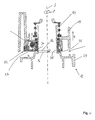
- FIG. 1a shows a vehicle mirror 10 in the form of a car mirror comprising a foot 12 and a mirror support 14.
- the foot 12 is configured to attach the vehicle mirror 10 to a front side of a door of a passenger car.
- the mirror support 14 is mounted about a pivot axis S on the foot 12 and is designed to receive a not shown mirror element in the form of a glass mirror with a mirror holder 16.
- FIG. 1b Enlarged locking device provided, which includes a latching projection 18 and a spring element 20 as a locking partner.
- a latching projection 18 and a spring element 20 as a locking partner.
- FIGS. 1a and 1b shown operating position of the locking projection 18 and the spring element 20 are spaced from each other and do not affect each other.
- ⁇ swivel angle
- FIG. 1 a is a partially hidden pivot drive 22 can be seen, which applies a torque between a horizontal portion 24 of the foot 12 and the mirror support 14.
- FIG. 4 shows a section along the pivot axis S in the direction of view B. It can be seen that the pivot drive 22 is rigidly connected to the mirror support 14. With the horizontal portion 24 of the foot 12 of the pivot drive 22 is connected via a latching coupling 26.
- the detent coupling 26 is a conventional 3-tooth detent, which has a first sliding surface 28, which constitutes a tooth base of the detent coupling 26, and a second sliding surface 30, which has a height raised relative to the first sliding surface 28.
- the detent clutch locks a pivoting movement from the foot 12 to the mirror support 14, 23nn between both a torque is applied, which is smaller than a detent clutch breakaway torque M 26th If the applied torque exceeds the latching clutch breakaway torque M 26 , the sliding surfaces slide against each other.
- the mirror support 14 can be brought into a parking position.
- the pivot drive 22 engages with a tooth 32 in the tooth base of the latching coupling 26 and thus is in contact with the first sliding surface 28. In this position, the pivot drive 22 is biased by a tension spring 34.
- the pivot drive 22 When the pivot drive 22 is set in motion, it pivots the mirror support 14 about the pivot axis S by the pivot angle ⁇ , during this pivoting movement of the tooth 32 always in contact with the first sliding surface 28 and rests relative thereto.
- the movement of the mirror carrier 14 thus takes place at a first height H 1 with respect to the pivot axis S.
- the height H of the pivoting movement is understood to mean the projection of a defined point, for example the tip of the tooth 32 selected in the present case, onto the pivot axis S.
- FIGS. 2a and 2b the parking position is shown, in which the mirror support 14 has been pivoted by means of the pivot drive 22, which is covered by the mirror support 14 in the figures.
- the tooth 32 has not changed its position relative to the first sliding surface 28, so that the pivotal movement has taken place at the first height H 1 .
- a recess 36 is provided, which causes a contact projection 38, which is formed on the spring element 20, does not come into contact with the latching projection 18.
- FIG. 3b shows the location of mirror support 14 relative to foot 12 in a pivotal movement at the second height H 2 .
- the recess 36 in the latching projection 18 is now at a different height with respect to the pivot axis S than the contact projection 38 of the spring element 20.
- the contact projection 38 comes into contact with the latching projection 18, whereby the spring element 20 elastically deflects radially outward and thereby the further pivoting a mechanical resistance opposes.
- a breakaway torque M 20 is necessary, wherein the index "20" indicates that the breakaway torque is caused by the spring element 20. It is advantageous if the breakaway torque M 20 is substantially as large as the breakaway torque M 26 , which is caused by the latching coupling 26.
- the interplay of the latching device which is formed by the latching projection 18 and the spring element 20 on the one hand and the latching coupling 26 on the other hand, causes the foot and the mirror support in the parking position are always reversibly locked together, whether this parking position using the pivot drive or manually set.
- the detent effect of the known 3-tooth detent movement ago is pivoted manually, the detent effect of the locking device ago.
- An unintentionally applied force such as by the brushes of a car wash, can not unfold the vehicle mirror again and damage is safely excluded.
Landscapes
- Engineering & Computer Science (AREA)
- Multimedia (AREA)
- Mechanical Engineering (AREA)
- Rear-View Mirror Devices That Are Mounted On The Exterior Of The Vehicle (AREA)
Applications Claiming Priority (1)
| Application Number | Priority Date | Filing Date | Title |
|---|---|---|---|
| DE200710022244 DE102007022244B3 (de) | 2007-05-09 | 2007-05-09 | Fahrzeugspiegel |
Publications (2)
| Publication Number | Publication Date |
|---|---|
| EP1990239A2 true EP1990239A2 (fr) | 2008-11-12 |
| EP1990239A3 EP1990239A3 (fr) | 2010-04-14 |
Family
ID=39591238
Family Applications (1)
| Application Number | Title | Priority Date | Filing Date |
|---|---|---|---|
| EP08008561A Withdrawn EP1990239A3 (fr) | 2007-05-09 | 2008-05-07 | Miroir de véhicule automobile |
Country Status (2)
| Country | Link |
|---|---|
| EP (1) | EP1990239A3 (fr) |
| DE (1) | DE102007022244B3 (fr) |
Families Citing this family (1)
| Publication number | Priority date | Publication date | Assignee | Title |
|---|---|---|---|---|
| DE102009003672A1 (de) | 2009-03-25 | 2010-09-30 | Mekra Lang Gmbh & Co. Kg | Gelenkverbindung |
Citations (7)
| Publication number | Priority date | Publication date | Assignee | Title |
|---|---|---|---|---|
| DE3538159C1 (de) | 1985-10-26 | 1987-02-26 | Daimler Benz Ag | Fernbedienbar verschwenkbarer Aussenspiegel fuer Nutzfahrzeuge |
| DE10023052A1 (de) | 2000-05-11 | 2001-11-15 | Reitter & Schefenacker Gmbh | Außenrückblickspiegel für Fahrzeuge, insbesondere für Kraftfahrzeuge |
| DE19833672C2 (de) | 1997-07-30 | 2003-01-23 | Buhler Motor Gmbh | Außenrückblickspiegel für Kraftfahrzeuge |
| DE60009737T2 (de) | 1999-02-05 | 2005-04-07 | Schefenacker Vision Systems Australia Pty Ltd, Lonsdale | Spiegelanordnung mit einem mit einer Tellerfeder vorgespanntem Gelenk |
| DE10009670B4 (de) | 2000-02-29 | 2005-08-04 | Bühler Motor GmbH | Außenrückblickspiegel für ein Kraftfahrzeug |
| DE102005021757A1 (de) | 2005-05-11 | 2006-11-16 | Schefenacker Vision Systems Germany Gmbh | Aussenrückblickspiegel für Fahrzeuge, vorzugsweise für Kraftfahrzeuge |
| DE102005049190A1 (de) | 2005-10-10 | 2007-04-12 | Schefenacker Vision Systems Germany Gmbh | Außenrückblickspiegel für Fahrzeuge, vorzugsweise für Kraftfahrzeuge |
-
2007
- 2007-05-09 DE DE200710022244 patent/DE102007022244B3/de not_active Expired - Fee Related
-
2008
- 2008-05-07 EP EP08008561A patent/EP1990239A3/fr not_active Withdrawn
Patent Citations (7)
| Publication number | Priority date | Publication date | Assignee | Title |
|---|---|---|---|---|
| DE3538159C1 (de) | 1985-10-26 | 1987-02-26 | Daimler Benz Ag | Fernbedienbar verschwenkbarer Aussenspiegel fuer Nutzfahrzeuge |
| DE19833672C2 (de) | 1997-07-30 | 2003-01-23 | Buhler Motor Gmbh | Außenrückblickspiegel für Kraftfahrzeuge |
| DE60009737T2 (de) | 1999-02-05 | 2005-04-07 | Schefenacker Vision Systems Australia Pty Ltd, Lonsdale | Spiegelanordnung mit einem mit einer Tellerfeder vorgespanntem Gelenk |
| DE10009670B4 (de) | 2000-02-29 | 2005-08-04 | Bühler Motor GmbH | Außenrückblickspiegel für ein Kraftfahrzeug |
| DE10023052A1 (de) | 2000-05-11 | 2001-11-15 | Reitter & Schefenacker Gmbh | Außenrückblickspiegel für Fahrzeuge, insbesondere für Kraftfahrzeuge |
| DE102005021757A1 (de) | 2005-05-11 | 2006-11-16 | Schefenacker Vision Systems Germany Gmbh | Aussenrückblickspiegel für Fahrzeuge, vorzugsweise für Kraftfahrzeuge |
| DE102005049190A1 (de) | 2005-10-10 | 2007-04-12 | Schefenacker Vision Systems Germany Gmbh | Außenrückblickspiegel für Fahrzeuge, vorzugsweise für Kraftfahrzeuge |
Also Published As
| Publication number | Publication date |
|---|---|
| EP1990239A3 (fr) | 2010-04-14 |
| DE102007022244B3 (de) | 2008-12-11 |
Similar Documents
| Publication | Publication Date | Title |
|---|---|---|
| DE102019122105B3 (de) | Kombinierter Aktuator zum Klappen und Anheben von Spiegeln, Rückblickeinrichtung und Fahrzeug | |
| EP2860067B1 (fr) | Mécanisme de pivotement destiné à l'application mobile d'une caméra sur un véhicule | |
| EP3194695B1 (fr) | Système de poignée de portière pour un véhicule automobile | |
| DE102017207161B4 (de) | Türanordnung mit integriertem Haltegriff | |
| DE102004062105B4 (de) | Vorrichtung zum Schutz von Personen bei einem Frontalaufprall auf ein Kraftfahrzeug durch aktives Aufstellen dessen Fronthaube | |
| EP3612696A1 (fr) | Système de poignée de porte d'un véhicule automobile | |
| EP1842992B1 (fr) | Serrure de capot | |
| WO2016142366A1 (fr) | Siège de véhicule à fonction easy-entry | |
| DE102023117792A1 (de) | Klapptischanordnung für ein Fahrzeug | |
| DE102018121432A1 (de) | Türgriffanordnung für ein Kraftfahrzeug | |
| EP3688256B1 (fr) | Agencement de poignée de porte d'une porte de véhicule | |
| DE10331625B3 (de) | Targadachsystem für ein Fahrzeug sowie Fahrzeug mit Targadachsystem | |
| EP3478521B1 (fr) | Dispositif d'ombrage pour une vitre de véhicule automobile | |
| DE102007014370A1 (de) | Fahrzeugsitz | |
| EP1026036A2 (fr) | Rétroviseur, en particulier rétroviseur extérieur pour véhicules | |
| EP1920962A2 (fr) | Capote pour un véhicule automobile, en particulier pour un véhicule de type cabriolet, avec un toit pliant | |
| EP2004448B1 (fr) | Systeme de deplacement d'un siege de vehicule | |
| EP1990239A2 (fr) | Miroir de véhicule automobile | |
| DE102015121272A1 (de) | Türgriffanordnung eines Kraftfahrzeugs | |
| EP1522470B1 (fr) | Systéme de protection pour capotage avec un arceau deploiable combiné avec un appui-tête | |
| EP1562799B1 (fr) | Dispositif pour inverser le mouvement du capot avant d'un vehicule releve par capteurs pour la protection contre les accidents | |
| DE102014216951B3 (de) | Verriegelungsvorrichtung | |
| DE202004010414U1 (de) | Vorrichtung zum Aufstellen der Fronthaube eines Kraftfahrzeuges zumindest im frontseitigen Haubenschloßbereich bei einem drohenden Personenaufprall mit einer Einrichtung zum Reversieren der aufgestellten Fronthaube | |
| DE102015106108A1 (de) | Versenkvorrichtung für ein Kühlerdekorelement | |
| WO2025061608A1 (fr) | Serrure de véhicule à moteur pour un élément de fermeture d'un véhicule à moteur |
Legal Events
| Date | Code | Title | Description |
|---|---|---|---|
| PUAI | Public reference made under article 153(3) epc to a published international application that has entered the european phase |
Free format text: ORIGINAL CODE: 0009012 |
|
| AK | Designated contracting states |
Kind code of ref document: A2 Designated state(s): AT BE BG CH CY CZ DE DK EE ES FI FR GB GR HR HU IE IS IT LI LT LU LV MC MT NL NO PL PT RO SE SI SK TR |
|
| AX | Request for extension of the european patent |
Extension state: AL BA MK RS |
|
| PUAL | Search report despatched |
Free format text: ORIGINAL CODE: 0009013 |
|
| AK | Designated contracting states |
Kind code of ref document: A3 Designated state(s): AT BE BG CH CY CZ DE DK EE ES FI FR GB GR HR HU IE IS IT LI LT LU LV MC MT NL NO PL PT RO SE SI SK TR |
|
| AX | Request for extension of the european patent |
Extension state: AL BA MK RS |
|
| RAP1 | Party data changed (applicant data changed or rights of an application transferred) |
Owner name: FICOSA INTERNATIONAL GMBH |
|
| AKY | No designation fees paid | ||
| STAA | Information on the status of an ep patent application or granted ep patent |
Free format text: STATUS: THE APPLICATION IS DEEMED TO BE WITHDRAWN |
|
| 18D | Application deemed to be withdrawn |
Effective date: 20101015 |
|
| REG | Reference to a national code |
Ref country code: DE Ref legal event code: R108 Effective date: 20110322 Ref country code: DE Ref legal event code: 8566 |