EP1990199B1 - Tintenpatrone mit einer Überwachungseinrichtung - Google Patents
Tintenpatrone mit einer Überwachungseinrichtung Download PDFInfo
- Publication number
- EP1990199B1 EP1990199B1 EP08008610.1A EP08008610A EP1990199B1 EP 1990199 B1 EP1990199 B1 EP 1990199B1 EP 08008610 A EP08008610 A EP 08008610A EP 1990199 B1 EP1990199 B1 EP 1990199B1
- Authority
- EP
- European Patent Office
- Prior art keywords
- ink cartridge
- ink
- functional device
- signal
- housing
- Prior art date
- Legal status (The legal status is an assumption and is not a legal conclusion. Google has not performed a legal analysis and makes no representation as to the accuracy of the status listed.)
- Not-in-force
Links
Images


Classifications
-
- B—PERFORMING OPERATIONS; TRANSPORTING
- B41—PRINTING; LINING MACHINES; TYPEWRITERS; STAMPS
- B41J—TYPEWRITERS; SELECTIVE PRINTING MECHANISMS, i.e. MECHANISMS PRINTING OTHERWISE THAN FROM A FORME; CORRECTION OF TYPOGRAPHICAL ERRORS
- B41J2/00—Typewriters or selective printing mechanisms characterised by the printing or marking process for which they are designed
- B41J2/005—Typewriters or selective printing mechanisms characterised by the printing or marking process for which they are designed characterised by bringing liquid or particles selectively into contact with a printing material
- B41J2/01—Ink jet
- B41J2/17—Ink jet characterised by ink handling
- B41J2/175—Ink supply systems ; Circuit parts therefor
- B41J2/17503—Ink cartridges
- B41J2/17543—Cartridge presence detection or type identification
- B41J2/17546—Cartridge presence detection or type identification electronically
-
- B—PERFORMING OPERATIONS; TRANSPORTING
- B41—PRINTING; LINING MACHINES; TYPEWRITERS; STAMPS
- B41J—TYPEWRITERS; SELECTIVE PRINTING MECHANISMS, i.e. MECHANISMS PRINTING OTHERWISE THAN FROM A FORME; CORRECTION OF TYPOGRAPHICAL ERRORS
- B41J2/00—Typewriters or selective printing mechanisms characterised by the printing or marking process for which they are designed
- B41J2/005—Typewriters or selective printing mechanisms characterised by the printing or marking process for which they are designed characterised by bringing liquid or particles selectively into contact with a printing material
- B41J2/01—Ink jet
- B41J2/17—Ink jet characterised by ink handling
- B41J2/175—Ink supply systems ; Circuit parts therefor
- B41J2/17503—Ink cartridges
- B41J2/1752—Mounting within the printer
-
- B—PERFORMING OPERATIONS; TRANSPORTING
- B41—PRINTING; LINING MACHINES; TYPEWRITERS; STAMPS
- B41J—TYPEWRITERS; SELECTIVE PRINTING MECHANISMS, i.e. MECHANISMS PRINTING OTHERWISE THAN FROM A FORME; CORRECTION OF TYPOGRAPHICAL ERRORS
- B41J2/00—Typewriters or selective printing mechanisms characterised by the printing or marking process for which they are designed
- B41J2/005—Typewriters or selective printing mechanisms characterised by the printing or marking process for which they are designed characterised by bringing liquid or particles selectively into contact with a printing material
- B41J2/01—Ink jet
- B41J2/17—Ink jet characterised by ink handling
- B41J2/175—Ink supply systems ; Circuit parts therefor
- B41J2/17503—Ink cartridges
- B41J2/17526—Electrical contacts to the cartridge
Definitions
- the present invention relates to an ink cartridge having a housing and at least one ink container, the ink cartridge having attachment means for detachable attachment to ink recording devices.
- Ink recorders also known as ink jet printers, are widely used in both personal and professional activities.
- the present invention is used in particular in the production of prints.
- ink to be applied is stored in ink tanks within the printer.
- ink tanks within the printer.
- different numbers of ink tanks are needed.
- a black-and-white printer only needs a black ink tank
- a color printer requires, for example, three ink tanks for different colors such as cyan, magenta and yellow.
- a large number of inkjet printers are used which have four ink tanks.
- ink tanks are the colors black, cyan, magenta and yellow. Still other embodiments have, for example, six tanks, wherein in addition to the colors black, cyan, magenta and yellow further intermediate colors are provided, which further improve the print quality of color representations.
- the ink Since the ink is a consumable, it is desirable for a user of an ink-jet recording apparatus to have as accurate information as possible about the condition of the individual ink cartridges with their ink tanks. Unintentional blank printing of one or more ink cartridges is disadvantageous in two respects. On the one hand, the printout during which the ink cartridge was emptied is usually useless since it is only partially completed. Here, not inconsiderable costs can arise due to the used printing medium, such as a photographic paper, and due to the already used ink.
- Another disadvantage of uncontrolled blank printing of an ink cartridge is that an inkjet printhead may be damaged under certain circumstances if insufficient ink reaches the printhead.
- surveillance devices are therefore known in the prior art which monitor certain properties, such as the filling level of the ink cartridge. If such an ink cartridge is then emptied or positioned incorrectly, for example, this can be detected and displayed in the known devices. This can be done, for example, by the use of an LED, which transmits information to a user by emitting a light signal.
- a monitoring device is for example from the EP 1 650 033 A1 which discloses an ink tank and an ink jet recording apparatus.
- a light signal is generated by means of a light-emitting device and forwarded via a massive light pipe section towards a display section.
- a disadvantage of the ink containers according to this document is that the use of a light guide additional material and additional Manufacturing steps required and may possibly represent a source of error.
- the light guide limits the choices of material used to make the cartridge and its color.
- Object of the present invention is therefore to provide an ink cartridge, which is cheaper to manufacture compared to the ink cartridges known in the art, is simpler in construction and in many cases requires less space.
- the object is achieved by an ink cartridge with a housing and at least one ink container according to the features of claim 1, wherein the ink cartridge fastening means for releasable attachment to ink recording devices, and having at least one functional device for generating and, wherein the functional device at least one signal in response from the state of the ink tank, and equipped with a transfer means connected thereto.
- the transmission means transmits the at least one signal between a first end at the functional device and a second end, which is spaced from the first end, wherein Transmission medium is air and the transmission means consists of two paths through air and at least one reflector for electromagnetic waves.
- the reflector is arranged to deflect the signal between the first and second ends.
- the ink cartridge according to the invention can be formed with a lower weight. In addition, less space is needed, which means that can be produced at a lower cost. Even a possible source of error, for example by inaccurate positioning of a light guide or a poor signal transition can be avoided.
- the provided on the ink cartridge functional device generates, for example, signals which correspond to the level or positioning of the ink cartridge within the ink recording device.
- these may be colored light signals, wherein, for example, a green means that the ink cartridge is sufficiently filled and in the correct location within the ink recording device.
- a green means that the ink cartridge is sufficiently filled and in the correct location within the ink recording device.
- an orange light signal or a red light signal for example, it may be indicated that the ink cartridge is in a wrong place within the ink recording apparatus or is almost completely emptied.
- Corresponding gradations can be made, for example, by the use of orange or red light signals. It is also possible that the ink cartridge communicates with the ink recording device via pulsed light sequences.
- the functional device may be suitable for processing electromagnetic signals.
- processing of electromagnetic signals provision may also be made for the functional device to query parameters or properties which are requested by the ink recording device. These requests can also edited and done by the subsequent output of appropriate response signals.
- air has been found in the context of the present invention as a very suitable transmission medium.
- Transmission means are understood to mean all means which, alone or in combination with others, are suitable for transmitting a signal from one end to another end.
- air serves as a transmission medium and thus as a transmission medium.
- components, such as reflectors which reflect or deflect the signal. According to the invention, air and the at least one reflector form the transmission means.
- the signal can also be diverted into distant and hidden areas to which there is no direct visual contact with the aid of the transmission means.
- the transmission means is designed as a reflector, for example for light waves.
- a light signal generated by the functional device can be deflected in a particularly simple manner to a desired range. It is quite possible to combine a plurality of transmission means or reflectors with each other, if a multiple deflection to achieve the predetermined destination for the signal is required.
- transmission means can also be used which filter and / or divide the signals generated before or after the deflection.
- the invention provides that at least one transmission means for deflecting the signal between the first and the second end is arranged.
- this transmission means comprises a reflector which deflects a light signal propagating along one side of an ink cartridge by approximately 90 degrees and then forwards, in particular leads away therefrom, along or parallel to a second side of the ink cartridge.
- this transmission means it is also possible, for example, to redirect a signal generated at a lower edge of the ink cartridge to the upper side thereof and then in a direction away from the ink cartridge. Such a signal could be perceived there, for example, by an operator at a front of an ink-jet recording device.
- the housing consists of at least two parts, wherein the functional device is arranged in a second housing portion of the housing, which is connected via connecting means releasably connected to a first housing portion of the housing.
- the housing of the ink cartridge is composed of at least two housing sections. If the functional device is arranged in a second, separate housing section, it is possible to exchange the empty first section comprising the ink container for a full first section with an empty ink cartridge and to obtain a ready-to-use ink cartridge again by reusing the previous second section. This is resource-saving and thus cost-effective.
- the connecting means has at least one longitudinal guide.
- a longitudinal guide may for example be designed in the form of a dovetail groove or other similar tongue and groove joints. This results in a positionally accurate guidance in two dimensions, so that only a longitudinal movement in the direction of the tongue and groove profile used is still possible.
- the longitudinal movement can then be limited for example by a particularly simple end stop, wherein when it reaches the first and second housing portion are positioned accurately to each other.
- the connecting means has at least one locking means.
- This can for example be designed so that the second housing portion is latched when reaching the intended position relative to the first housing portion and is fixed in its predetermined end position. Only when replacing the first housing section against a new and filled with ink housing portion, these locking means are then preferably releasable again to remove the second housing portion and assemble with the new first housing portion.
- latching means are understood to mean a device which, in the latched state, permits movement in a first direction, while preventing movement in a second direction opposite thereto as long as the latching is not released. The locking is usually achieved by an undercut arrangement in the direction of movement.
- the second housing portion is at least partially formed as a fastening means.
- Known ink cartridges usually need to be within the ink recording devices in a particular location be positioned, for which fastening means are provided.
- the second housing section is now designed such that it comprises at least a part of these fastening means. This is done in such a way that the ink cartridge according to the invention assembled from the first and second housing sections comprises in total the required fastening means for easy insertion in an ink recording device.
- the fastening means comprise at least one locking means.
- Such locking means may be formed, for example in the form of a long tab with a protruding latching lug which locks when inserting the ink cartridge in the ink recording device and only by deflection of the tab, the ink cartridge releases again to remove them from the ink recording device can.
- the ink cartridges according to the present invention when the functional device has electronic components and electrical connection means.
- electronic components such as small board mounted electronic components and integrated circuits
- relatively complex monitoring of the ink cartridge can be done with high accuracy. For example, fill levels, location detections, temperatures or similar parameters can be monitored with the aid of such functional devices.
- encodings of ink cartridges can also be checked to prevent inadvertent use of inappropriate ink cartridges.
- the further provided electrical connection means serve either for supplying electrical energy or for transmitting further signals in wired form to other sections of an ink recording device.
- a particularly simple type of power supply can be achieved if the functional device has means for inductive energy supply.
- a particularly favorable property of the inductive energy transmission is that there is virtually no wear here. It can thus be created a particularly durable device.
- the second end of the transmission means is designed as a display device or is connected directly or indirectly to a display device.
- a display device may be, for example, a scattering optics, which scatters a guided to the second end of the transmission means light signal, so that it is particularly easy to perceive by an operator.
- Other embodiments may provide that the light signal is transmitted directly or via further transmission means to display devices in order to provide it there to the operators in a suitable form.
- the ink cartridge may in principle be made of any suitable materials, suitable materials are known from the prior art.
- Another particular advantage of the ink cartridges according to the invention consists, for example, in that the cartridge can consist wholly or partly of opaque or colored material, without having to take into account the light-conducting properties of the cartridge or a part of the cartridge. It is particularly advantageous, for example, if that part of the cartridge that carries the functional device can be colored or colored.
- a functional device may be associated with a particular color of ink, so that it brings with it particular advantages when the Part of the cartridge carrying functional device has a corresponding coloring, for example cyan, magenta, yellow, blue or black.
- the part of the ink cartridge carrying the functional device is designed in such a way that it is removable and suitable for re-attachment. In this way, it can be ensured, in particular, that an ink cartridge designed with a correspondingly removable functional device can be easily assigned to the corresponding ink color when the detachable functional device is reused together with the part of the ink cartridge carrying the functional device, so that malfunctions do not occur.
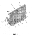
- FIG. 1 an ink cartridge 1 according to the invention is shown in an oblique view.
- the ink cartridge 1 has a housing 2, which is formed from a first section 3, a second section 4 and a third section 5.
- the first section 3 forms an ink container 6 and the third section 5 a lid 7, which closes the ink container 6 arranged in the first section 3.
- a recess 8 At the bottom of the Ink tank 6 is a recess 8.
- the recess 8 forms together with a nozzle 9 and a detent 10 formed as a latching means the fastening means 11 for fixing the ink cartridge 1 in an ink recording device, not shown.
- Such an ink jet recording apparatus may be, for example, an ink jet printer.
- the second section 4 is connected to the ink tank 6 by a connecting means 12, which is formed as a groove-shaped longitudinal guide. When inserted, in the ink container 6 held and not shown ink is passed through the nozzle 9 to a print head of the ink recording device, also not shown.
- the second section 4 can be embodied, for example, in a color which corresponds to the coding of a functional device 13.
- the functional device 13 On the underside of the second section 4 is also still the functional device 13, which can produce at least one signal 21 depending on the state of the ink container 1 and radiates to a cover 7 arranged on the reflector 22, which is part of a transmission means 14.
- the signal 21 is presently a light signal in the visible spectrum.
- the transmission means 14 therefore consists of two paths through the ambient air and a reflector 22.
- the reflector 22 is adapted to reflect the signal 21 on its surface and thereby redirect.
- Fig. 2 is the ink cartridge 1 after Fig. 1 shown again in an exploded view.
- the lid 7 is lifted from the housing 2.
- connecting means 12 which is formed by complementarily shaped elongated profile pieces at the respective first and second sections 3, 4.
- the connecting means 12 forms a longitudinal guide, which leads the sections 3 and 4 almost free of play to each other. Only the movement in the longitudinal direction of the connecting means 12 is thus still possible.
- a stop surface 15 is provided on the housing 2 at the bottom of the longitudinal guide 12, to which the second portion 4 comes into contact with the longitudinal guide of the connecting means 12 when inserted.
- locking means 10 can also be provided between the first section 3 and the second section 4, which fix the second section 4 in the position thus achieved, and prevent accidental slipping out of the longitudinal guide 12, as long as the locking means 10 are not released.
- an ink cartridge 1 according to the invention is shown schematically in a side view.
- the ink cartridge 1 shown here is a similarly constructed ink cartridge 1, as previously in connection with the FIGS. 1 and 2 has been described. Particularly well recognizable here is the mode of operation of the signal transmission.
- the signal 21 is first generated by a light-emitting component 16 of the functional device 13 and radiated in the direction of the reflector 22 of the transmission means 14. There, the signal 21 is reflected and directed away from the ink cartridge 1 in the horizontal direction.
- the direction in which the signal 21 is led away from the ink cartridge 1 corresponds to the laws of optical reflections, according to which the angle of incidence of the signal 21 on the reflector of the transmission means 14 is equal to the angle of reflection.
- This set in relation to the reflection surface of the reflector means that a vertical radiation of the reflection surface of the transmission means 14, which is aligned at 45 degrees to the vertical, a horizontal radiation is achieved to the left.
- the total deflection by the transmission means 14 is thus 90 °.
- the signal 21 puts in the transmission indicated by the dashed lines distances back to it reaches the lying on the arrowhead 19 second end 20.
- the functional device 13 comprises a plurality of components, such as electronic semiconductor components, capacitors, resistors or similar elements.
- the functional device 13 has a light-emitting component 16 which, in the presence of a defined state of the ink cartridge 1, generates a signal 21 corresponding to the state in the form of a light signal.
- the functional device 13 has a plurality of electrical contacts 17, for example two, three or in particular four. In the embodiment shown here, the electrical contacts 17 serve to provide energy in electrical form for the operation of the electrical functional device 13. In addition, however, signals can also be transmitted via such contacts 17 in each direction.
- the exemplary embodiments of the present invention shown above all have the advantage that air is used as the transmission medium for signals 21 to be transmitted from a first end 18 located at the light-emitting component 16 to a second end 20 lying at the arrow end 19.
- air is used as the transmission medium for signals 21 to be transmitted from a first end 18 located at the light-emitting component 16 to a second end 20 lying at the arrow end 19.
Landscapes
- Ink Jet (AREA)
Priority Applications (1)
| Application Number | Priority Date | Filing Date | Title |
|---|---|---|---|
| PL08008610T PL1990199T3 (pl) | 2007-05-08 | 2008-05-07 | Wkład atramentowy z urządzeniem kontrolującym |
Applications Claiming Priority (1)
| Application Number | Priority Date | Filing Date | Title |
|---|---|---|---|
| DE102007021562A DE102007021562B4 (de) | 2007-05-08 | 2007-05-08 | Tintenpatrone |
Publications (2)
| Publication Number | Publication Date |
|---|---|
| EP1990199A1 EP1990199A1 (de) | 2008-11-12 |
| EP1990199B1 true EP1990199B1 (de) | 2013-12-11 |
Family
ID=39596501
Family Applications (1)
| Application Number | Title | Priority Date | Filing Date |
|---|---|---|---|
| EP08008610.1A Not-in-force EP1990199B1 (de) | 2007-05-08 | 2008-05-07 | Tintenpatrone mit einer Überwachungseinrichtung |
Country Status (4)
| Country | Link |
|---|---|
| EP (1) | EP1990199B1 (pl) |
| DE (1) | DE102007021562B4 (pl) |
| ES (1) | ES2452345T3 (pl) |
| PL (1) | PL1990199T3 (pl) |
Families Citing this family (4)
| Publication number | Priority date | Publication date | Assignee | Title |
|---|---|---|---|---|
| DE102009002738A1 (de) | 2009-03-07 | 2010-09-23 | Gühring Ohg | Schaftfräser |
| GB2473063A (en) * | 2009-08-28 | 2011-03-02 | Dynamic Cassette Int | Ink cartridge for a printer |
| JP6354117B2 (ja) * | 2012-08-31 | 2018-07-11 | セイコーエプソン株式会社 | 保持部材、および液体収容容器 |
| JP3186994U (ja) * | 2013-08-23 | 2013-10-31 | 剛志 前田 | インクカートリッジ |
Family Cites Families (7)
| Publication number | Priority date | Publication date | Assignee | Title |
|---|---|---|---|---|
| JP3221210B2 (ja) * | 1994-02-07 | 2001-10-22 | 富士ゼロックス株式会社 | インクタンク |
| US6097405A (en) * | 1996-09-30 | 2000-08-01 | Hewlett-Packard Company | Detection apparatus and method for use in a printing device |
| DE10019223A1 (de) * | 2000-04-18 | 2001-10-31 | Pelikan Produktions Ag Egg | System zum Erfassen eines Flüssigkeitsstandes in einem Behälter |
| JP4125279B2 (ja) * | 2004-10-20 | 2008-07-30 | キヤノン株式会社 | インクタンク、該インクタンクを搭載するホルダを備えたインクジェット記録装置およびインクタンクとホルダとを備えたインクジェット記録システム |
| JP4533125B2 (ja) * | 2004-10-20 | 2010-09-01 | キヤノン株式会社 | インクタンクおよびインクジェット記録装置 |
| JP4101230B2 (ja) * | 2004-12-08 | 2008-06-18 | キヤノン株式会社 | 液体貯蔵容器および記録装置 |
| JP4047328B2 (ja) * | 2004-12-24 | 2008-02-13 | キヤノン株式会社 | 液体収納容器、該容器を用いる液体供給システムおよび記録装置、並びに前記容器用回路基板 |
-
2007
- 2007-05-08 DE DE102007021562A patent/DE102007021562B4/de not_active Expired - Fee Related
-
2008
- 2008-05-07 PL PL08008610T patent/PL1990199T3/pl unknown
- 2008-05-07 ES ES08008610.1T patent/ES2452345T3/es active Active
- 2008-05-07 EP EP08008610.1A patent/EP1990199B1/de not_active Not-in-force
Also Published As
| Publication number | Publication date |
|---|---|
| DE102007021562B4 (de) | 2012-05-03 |
| ES2452345T3 (es) | 2014-04-01 |
| DE102007021562A1 (de) | 2008-11-13 |
| EP1990199A1 (de) | 2008-11-12 |
| PL1990199T3 (pl) | 2014-08-29 |
Similar Documents
| Publication | Publication Date | Title |
|---|---|---|
| DE19732628B4 (de) | Erfassungsvorrichtung und Erfassungsverfahren zur Verwendung in einem Druckgerät | |
| DE69729520T2 (de) | Verbindungsmethode für Tintenstrahlkopfeinheiten, Tintenstrahlkopfeinheit und Tintenkassette | |
| DE60314204T2 (de) | Vorrichtung zum Laden und Zuführen für feste Tinte | |
| DE60310804T2 (de) | Kodierungsmerkmal für festen Tintenstift | |
| DE69423999T2 (de) | Tintenstrahlaufzeichnungsvorrichtung | |
| DE102005063486B3 (de) | Tintenstrahldruckvorrichtung | |
| DE60317965T2 (de) | Kodierter Zuführungskanal zur Zufuhr von festen Tintenstiften | |
| DE69723737T2 (de) | Tintenbehälter mit elektronischen und mechanischen merkmalen, der zwischen verschiedenen versorgungsgrössen steckerkompabilität erlaubt | |
| DE60310835T2 (de) | Tintenbehälter und Aufzeichnungsgerät | |
| DE69922128T2 (de) | Tintenstrahldrucksystem das eine modulare Tintenpatronenbaugruppe verwendet | |
| DE69804148T2 (de) | Mechanische und elektrische Kodierungsvorrichtung für austauschbare Tintenpatrone | |
| DE60313395T2 (de) | Vorrichtung zum Laden und Zuführen für feste Tinte | |
| EP1990199B1 (de) | Tintenpatrone mit einer Überwachungseinrichtung | |
| EP2250021B1 (de) | Tintenpatrone mit leiterplattenelement | |
| DE69325980T2 (de) | Flüssigkeitsausstosskopf und Flüssigkeitsausstossgerät | |
| DE60302271T2 (de) | Tintenstrahldruckgerät und Steuerungsverfahren dafür | |
| DE60310304T2 (de) | Vorrichtung zum Laden und Zuführen für feste Tinte | |
| DE69715529T2 (de) | Kodierungsvorrichtung für Tintenzufuhrbehälter | |
| EP2578363B1 (de) | Vorrichtung zum Bereithalten von wenigstens einem Werkzeugeinsatz | |
| DE60020649T2 (de) | Schlitten mit Shutzabdeckung für die elektrischen Verbindungskontakte und Aufzeichnungsgerät | |
| DE60311349T2 (de) | Vorrichtung zum Laden und Zuführen für feste Tinte | |
| DE69603037T2 (de) | Tintenstrahldrucker | |
| DE202007019337U1 (de) | Tintenpatrone | |
| DE2739538A1 (de) | Steuerschalter mit wenigstens einem, in einem bestimmten bewegungsbereich betaetigbaren schalter in verbindung mit einem sollwertgeber | |
| DE69122846T2 (de) | Verbinder für die Kupplung eines Druckkopfes mit einer Schaltung in einem Drucker |
Legal Events
| Date | Code | Title | Description |
|---|---|---|---|
| PUAI | Public reference made under article 153(3) epc to a published international application that has entered the european phase |
Free format text: ORIGINAL CODE: 0009012 |
|
| 17P | Request for examination filed |
Effective date: 20080507 |
|
| AK | Designated contracting states |
Kind code of ref document: A1 Designated state(s): AT BE BG CH CY CZ DE DK EE ES FI FR GB GR HR HU IE IS IT LI LT LU LV MC MT NL NO PL PT RO SE SI SK TR |
|
| AX | Request for extension of the european patent |
Extension state: AL BA MK RS |
|
| 17Q | First examination report despatched |
Effective date: 20090528 |
|
| AKX | Designation fees paid |
Designated state(s): AT BE BG CH CY CZ DE DK EE ES FI FR GB GR HR HU IE IS IT LI LT LU LV MC MT NL NO PL PT RO SE SI SK TR |
|
| GRAP | Despatch of communication of intention to grant a patent |
Free format text: ORIGINAL CODE: EPIDOSNIGR1 |
|
| INTG | Intention to grant announced |
Effective date: 20130619 |
|
| GRAS | Grant fee paid |
Free format text: ORIGINAL CODE: EPIDOSNIGR3 |
|
| GRAA | (expected) grant |
Free format text: ORIGINAL CODE: 0009210 |
|
| RAP1 | Party data changed (applicant data changed or rights of an application transferred) |
Owner name: KMP PRINTTECHNIK AG |
|
| RIN1 | Information on inventor provided before grant (corrected) |
Inventor name: NESTL, THOMAS, DR. Inventor name: WELACK, MARKUS |
|
| AK | Designated contracting states |
Kind code of ref document: B1 Designated state(s): AT BE BG CH CY CZ DE DK EE ES FI FR GB GR HR HU IE IS IT LI LT LU LV MC MT NL NO PL PT RO SE SI SK TR |
|
| REG | Reference to a national code |
Ref country code: GB Ref legal event code: FG4D Free format text: NOT ENGLISH |
|
| REG | Reference to a national code |
Ref country code: CH Ref legal event code: EP |
|
| REG | Reference to a national code |
Ref country code: AT Ref legal event code: REF Ref document number: 644290 Country of ref document: AT Kind code of ref document: T Effective date: 20140115 |
|
| REG | Reference to a national code |
Ref country code: IE Ref legal event code: FG4D Free format text: LANGUAGE OF EP DOCUMENT: GERMAN |
|
| REG | Reference to a national code |
Ref country code: DE Ref legal event code: R096 Ref document number: 502008011038 Country of ref document: DE Effective date: 20140206 |
|
| REG | Reference to a national code |
Ref country code: ES Ref legal event code: FG2A Ref document number: 2452345 Country of ref document: ES Kind code of ref document: T3 Effective date: 20140401 |
|
| REG | Reference to a national code |
Ref country code: NL Ref legal event code: VDEP Effective date: 20131211 |
|
| PG25 | Lapsed in a contracting state [announced via postgrant information from national office to epo] |
Ref country code: LT Free format text: LAPSE BECAUSE OF FAILURE TO SUBMIT A TRANSLATION OF THE DESCRIPTION OR TO PAY THE FEE WITHIN THE PRESCRIBED TIME-LIMIT Effective date: 20131211 Ref country code: SE Free format text: LAPSE BECAUSE OF FAILURE TO SUBMIT A TRANSLATION OF THE DESCRIPTION OR TO PAY THE FEE WITHIN THE PRESCRIBED TIME-LIMIT Effective date: 20131211 Ref country code: NL Free format text: LAPSE BECAUSE OF FAILURE TO SUBMIT A TRANSLATION OF THE DESCRIPTION OR TO PAY THE FEE WITHIN THE PRESCRIBED TIME-LIMIT Effective date: 20131211 Ref country code: HR Free format text: LAPSE BECAUSE OF FAILURE TO SUBMIT A TRANSLATION OF THE DESCRIPTION OR TO PAY THE FEE WITHIN THE PRESCRIBED TIME-LIMIT Effective date: 20131211 Ref country code: NO Free format text: LAPSE BECAUSE OF FAILURE TO SUBMIT A TRANSLATION OF THE DESCRIPTION OR TO PAY THE FEE WITHIN THE PRESCRIBED TIME-LIMIT Effective date: 20140311 Ref country code: FI Free format text: LAPSE BECAUSE OF FAILURE TO SUBMIT A TRANSLATION OF THE DESCRIPTION OR TO PAY THE FEE WITHIN THE PRESCRIBED TIME-LIMIT Effective date: 20131211 |
|
| REG | Reference to a national code |
Ref country code: LT Ref legal event code: MG4D |
|
| PG25 | Lapsed in a contracting state [announced via postgrant information from national office to epo] |
Ref country code: LV Free format text: LAPSE BECAUSE OF FAILURE TO SUBMIT A TRANSLATION OF THE DESCRIPTION OR TO PAY THE FEE WITHIN THE PRESCRIBED TIME-LIMIT Effective date: 20131211 Ref country code: CY Free format text: LAPSE BECAUSE OF FAILURE TO SUBMIT A TRANSLATION OF THE DESCRIPTION OR TO PAY THE FEE WITHIN THE PRESCRIBED TIME-LIMIT Effective date: 20131211 |
|
| PG25 | Lapsed in a contracting state [announced via postgrant information from national office to epo] |
Ref country code: EE Free format text: LAPSE BECAUSE OF FAILURE TO SUBMIT A TRANSLATION OF THE DESCRIPTION OR TO PAY THE FEE WITHIN THE PRESCRIBED TIME-LIMIT Effective date: 20131211 Ref country code: IS Free format text: LAPSE BECAUSE OF FAILURE TO SUBMIT A TRANSLATION OF THE DESCRIPTION OR TO PAY THE FEE WITHIN THE PRESCRIBED TIME-LIMIT Effective date: 20140411 |
|
| PG25 | Lapsed in a contracting state [announced via postgrant information from national office to epo] |
Ref country code: PT Free format text: LAPSE BECAUSE OF FAILURE TO SUBMIT A TRANSLATION OF THE DESCRIPTION OR TO PAY THE FEE WITHIN THE PRESCRIBED TIME-LIMIT Effective date: 20140411 Ref country code: SK Free format text: LAPSE BECAUSE OF FAILURE TO SUBMIT A TRANSLATION OF THE DESCRIPTION OR TO PAY THE FEE WITHIN THE PRESCRIBED TIME-LIMIT Effective date: 20131211 Ref country code: RO Free format text: LAPSE BECAUSE OF FAILURE TO SUBMIT A TRANSLATION OF THE DESCRIPTION OR TO PAY THE FEE WITHIN THE PRESCRIBED TIME-LIMIT Effective date: 20131211 Ref country code: CZ Free format text: LAPSE BECAUSE OF FAILURE TO SUBMIT A TRANSLATION OF THE DESCRIPTION OR TO PAY THE FEE WITHIN THE PRESCRIBED TIME-LIMIT Effective date: 20131211 |
|
| REG | Reference to a national code |
Ref country code: PL Ref legal event code: T3 |
|
| REG | Reference to a national code |
Ref country code: DE Ref legal event code: R097 Ref document number: 502008011038 Country of ref document: DE |
|
| PLBE | No opposition filed within time limit |
Free format text: ORIGINAL CODE: 0009261 |
|
| STAA | Information on the status of an ep patent application or granted ep patent |
Free format text: STATUS: NO OPPOSITION FILED WITHIN TIME LIMIT |
|
| PG25 | Lapsed in a contracting state [announced via postgrant information from national office to epo] |
Ref country code: DK Free format text: LAPSE BECAUSE OF FAILURE TO SUBMIT A TRANSLATION OF THE DESCRIPTION OR TO PAY THE FEE WITHIN THE PRESCRIBED TIME-LIMIT Effective date: 20131211 |
|
| 26N | No opposition filed |
Effective date: 20140912 |
|
| REG | Reference to a national code |
Ref country code: DE Ref legal event code: R097 Ref document number: 502008011038 Country of ref document: DE Effective date: 20140912 |
|
| PG25 | Lapsed in a contracting state [announced via postgrant information from national office to epo] |
Ref country code: LU Free format text: LAPSE BECAUSE OF FAILURE TO SUBMIT A TRANSLATION OF THE DESCRIPTION OR TO PAY THE FEE WITHIN THE PRESCRIBED TIME-LIMIT Effective date: 20140507 |
|
| REG | Reference to a national code |
Ref country code: CH Ref legal event code: PL |
|
| PG25 | Lapsed in a contracting state [announced via postgrant information from national office to epo] |
Ref country code: MC Free format text: LAPSE BECAUSE OF FAILURE TO SUBMIT A TRANSLATION OF THE DESCRIPTION OR TO PAY THE FEE WITHIN THE PRESCRIBED TIME-LIMIT Effective date: 20131211 Ref country code: CH Free format text: LAPSE BECAUSE OF NON-PAYMENT OF DUE FEES Effective date: 20140531 Ref country code: LI Free format text: LAPSE BECAUSE OF NON-PAYMENT OF DUE FEES Effective date: 20140531 |
|
| REG | Reference to a national code |
Ref country code: IE Ref legal event code: MM4A |
|
| PG25 | Lapsed in a contracting state [announced via postgrant information from national office to epo] |
Ref country code: SI Free format text: LAPSE BECAUSE OF FAILURE TO SUBMIT A TRANSLATION OF THE DESCRIPTION OR TO PAY THE FEE WITHIN THE PRESCRIBED TIME-LIMIT Effective date: 20131211 |
|
| PG25 | Lapsed in a contracting state [announced via postgrant information from national office to epo] |
Ref country code: IE Free format text: LAPSE BECAUSE OF NON-PAYMENT OF DUE FEES Effective date: 20140507 |
|
| REG | Reference to a national code |
Ref country code: AT Ref legal event code: MM01 Ref document number: 644290 Country of ref document: AT Kind code of ref document: T Effective date: 20140507 |
|
| PG25 | Lapsed in a contracting state [announced via postgrant information from national office to epo] |
Ref country code: AT Free format text: LAPSE BECAUSE OF NON-PAYMENT OF DUE FEES Effective date: 20140507 |
|
| PG25 | Lapsed in a contracting state [announced via postgrant information from national office to epo] |
Ref country code: MT Free format text: LAPSE BECAUSE OF FAILURE TO SUBMIT A TRANSLATION OF THE DESCRIPTION OR TO PAY THE FEE WITHIN THE PRESCRIBED TIME-LIMIT Effective date: 20131211 |
|
| REG | Reference to a national code |
Ref country code: FR Ref legal event code: PLFP Year of fee payment: 9 |
|
| PG25 | Lapsed in a contracting state [announced via postgrant information from national office to epo] |
Ref country code: BG Free format text: LAPSE BECAUSE OF FAILURE TO SUBMIT A TRANSLATION OF THE DESCRIPTION OR TO PAY THE FEE WITHIN THE PRESCRIBED TIME-LIMIT Effective date: 20131211 |
|
| PG25 | Lapsed in a contracting state [announced via postgrant information from national office to epo] |
Ref country code: GR Free format text: LAPSE BECAUSE OF FAILURE TO SUBMIT A TRANSLATION OF THE DESCRIPTION OR TO PAY THE FEE WITHIN THE PRESCRIBED TIME-LIMIT Effective date: 20140312 |
|
| PG25 | Lapsed in a contracting state [announced via postgrant information from national office to epo] |
Ref country code: HU Free format text: LAPSE BECAUSE OF FAILURE TO SUBMIT A TRANSLATION OF THE DESCRIPTION OR TO PAY THE FEE WITHIN THE PRESCRIBED TIME-LIMIT; INVALID AB INITIO Effective date: 20080507 Ref country code: BE Free format text: LAPSE BECAUSE OF FAILURE TO SUBMIT A TRANSLATION OF THE DESCRIPTION OR TO PAY THE FEE WITHIN THE PRESCRIBED TIME-LIMIT Effective date: 20140531 Ref country code: TR Free format text: LAPSE BECAUSE OF FAILURE TO SUBMIT A TRANSLATION OF THE DESCRIPTION OR TO PAY THE FEE WITHIN THE PRESCRIBED TIME-LIMIT Effective date: 20131211 |
|
| REG | Reference to a national code |
Ref country code: FR Ref legal event code: PLFP Year of fee payment: 10 |
|
| REG | Reference to a national code |
Ref country code: FR Ref legal event code: PLFP Year of fee payment: 11 |
|
| PGFP | Annual fee paid to national office [announced via postgrant information from national office to epo] |
Ref country code: TR Payment date: 20190521 Year of fee payment: 16 Ref country code: ES Payment date: 20190613 Year of fee payment: 12 Ref country code: PL Payment date: 20190424 Year of fee payment: 12 |
|
| PGFP | Annual fee paid to national office [announced via postgrant information from national office to epo] |
Ref country code: FR Payment date: 20190524 Year of fee payment: 12 |
|
| PGFP | Annual fee paid to national office [announced via postgrant information from national office to epo] |
Ref country code: GB Payment date: 20190524 Year of fee payment: 12 |
|
| GBPC | Gb: european patent ceased through non-payment of renewal fee |
Effective date: 20200507 |
|
| PG25 | Lapsed in a contracting state [announced via postgrant information from national office to epo] |
Ref country code: GB Free format text: LAPSE BECAUSE OF NON-PAYMENT OF DUE FEES Effective date: 20200507 Ref country code: FR Free format text: LAPSE BECAUSE OF NON-PAYMENT OF DUE FEES Effective date: 20200531 |
|
| REG | Reference to a national code |
Ref country code: ES Ref legal event code: FD2A Effective date: 20210927 |
|
| PG25 | Lapsed in a contracting state [announced via postgrant information from national office to epo] |
Ref country code: IT Free format text: LAPSE BECAUSE OF NON-PAYMENT OF DUE FEES Effective date: 20200507 |
|
| PG25 | Lapsed in a contracting state [announced via postgrant information from national office to epo] |
Ref country code: ES Free format text: LAPSE BECAUSE OF NON-PAYMENT OF DUE FEES Effective date: 20200508 |
|
| PG25 | Lapsed in a contracting state [announced via postgrant information from national office to epo] |
Ref country code: PL Free format text: LAPSE BECAUSE OF NON-PAYMENT OF DUE FEES Effective date: 20200507 |
|
| PGFP | Annual fee paid to national office [announced via postgrant information from national office to epo] |
Ref country code: DE Payment date: 20240524 Year of fee payment: 17 |
|
| REG | Reference to a national code |
Ref country code: DE Ref legal event code: R119 Ref document number: 502008011038 Country of ref document: DE |