EP1989349B1 - Procédé et dispositif de traitement du linge par voie humide - Google Patents
Procédé et dispositif de traitement du linge par voie humide Download PDFInfo
- Publication number
- EP1989349B1 EP1989349B1 EP07722850.0A EP07722850A EP1989349B1 EP 1989349 B1 EP1989349 B1 EP 1989349B1 EP 07722850 A EP07722850 A EP 07722850A EP 1989349 B1 EP1989349 B1 EP 1989349B1
- Authority
- EP
- European Patent Office
- Prior art keywords
- chamber
- chambers
- zone
- rinsing
- laundry
- Prior art date
- Legal status (The legal status is an assumption and is not a legal conclusion. Google has not performed a legal analysis and makes no representation as to the accuracy of the status listed.)
- Not-in-force
Links
- 238000011282 treatment Methods 0.000 title claims description 62
- 238000000034 method Methods 0.000 title claims description 38
- 238000005406 washing Methods 0.000 claims description 71
- 239000013505 freshwater Substances 0.000 claims description 51
- 238000007599 discharging Methods 0.000 claims description 3
- 239000012530 fluid Substances 0.000 claims 12
- 239000007788 liquid Substances 0.000 description 61
- XLYOFNOQVPJJNP-UHFFFAOYSA-N water Substances O XLYOFNOQVPJJNP-UHFFFAOYSA-N 0.000 description 9
- 239000003795 chemical substances by application Substances 0.000 description 6
- 238000002156 mixing Methods 0.000 description 4
- 238000004061 bleaching Methods 0.000 description 3
- 238000011010 flushing procedure Methods 0.000 description 3
- 239000003086 colorant Substances 0.000 description 2
- 238000010790 dilution Methods 0.000 description 2
- 239000012895 dilution Substances 0.000 description 2
- 238000004851 dishwashing Methods 0.000 description 2
- 238000006386 neutralization reaction Methods 0.000 description 2
- 230000003472 neutralizing effect Effects 0.000 description 2
- 239000008237 rinsing water Substances 0.000 description 2
- 229920002472 Starch Polymers 0.000 description 1
- 239000002253 acid Substances 0.000 description 1
- 239000000654 additive Substances 0.000 description 1
- 238000003287 bathing Methods 0.000 description 1
- 230000000694 effects Effects 0.000 description 1
- 230000002349 favourable effect Effects 0.000 description 1
- 238000002955 isolation Methods 0.000 description 1
- 238000004519 manufacturing process Methods 0.000 description 1
- 239000000463 material Substances 0.000 description 1
- 238000010926 purge Methods 0.000 description 1
- 239000002516 radical scavenger Substances 0.000 description 1
- 235000019698 starch Nutrition 0.000 description 1
- 238000009955 starching Methods 0.000 description 1
- 238000003860 storage Methods 0.000 description 1
- 238000005728 strengthening Methods 0.000 description 1
Images


Classifications
-
- D—TEXTILES; PAPER
- D06—TREATMENT OF TEXTILES OR THE LIKE; LAUNDERING; FLEXIBLE MATERIALS NOT OTHERWISE PROVIDED FOR
- D06F—LAUNDERING, DRYING, IRONING, PRESSING OR FOLDING TEXTILE ARTICLES
- D06F31/00—Washing installations comprising an assembly of several washing machines or washing units, e.g. continuous flow assemblies
- D06F31/005—Washing installations comprising an assembly of several washing machines or washing units, e.g. continuous flow assemblies consisting of one or more rotating drums through which the laundry passes in a continuous flow
Definitions
- the invention relates to a method for wet-treating laundry according to the preamble of claim 1. Furthermore, the invention relates to a device for wet treatment of laundry according to the preamble of claim 10.
- the method and the device of the type mentioned here relate to so-called continuous washing machines for commercial laundries.
- Such continuous washing machines such as EP-0 063 476 have a rotating drivable, elongated drum.
- the laundry is conveyed longitudinally through the drum.
- the laundry gradually passes through the individual chambers, where it remains in each chamber for a certain time.
- the chambers form in the drum a prewash zone, a final wash zone and a rinse zone.
- a post-treatment for example, equipment
- the pre-wash, clear wash and rinse zones are formed depending on the size and purpose of the continuous washing machine from one or more successive chambers.
- the invention has for its object to provide a method and apparatus for wet treatment of laundry, which are flexible in terms of the type of laundry to be processed and ensure the greatest possible efficiency.
- a method for achieving this object comprises the measures of claim 1.
- the treatment liquid such as rinsing liquid or optionally also aftertreatment liquid
- the laundry items are thus each rinsed with their own treatment liquid or aftertreated. Due to the invention, the laundry items are always reloaded into virtually empty chambers, in which there is no or almost no treatment liquid, with which the preceding laundry item has been rinsed. It has also been shown that with the same use of fresh water compared with working on the counterflow principle continuous washing a better dishwashing result is achieved because virtually no rinse water is carried into adjacent chambers, resulting in a more favorable dilution ratio and the laundry can be individually rinsed, especially with one adapted to the respective laundry items treatment liquid.
- At least one bath change is carried out in the rinsing zone serving for rinsing and optionally also for aftertreatment by discharging and supplying treatment liquids.
- the treatment liquid to be removed is rinsing liquid or aftertreatment liquid.
- the supplied treatment liquid is usually fresh water.
- additives can be added to the fresh water, especially in the case of carrying out a post-treatment, for example finishing agents.
- the rinsing of the respective laundry item takes place in this way with fresh water, without the batch of laundry is mixed with rinse water from the area of another Wäschepostens. It is also conceivable to load the laundry without the treatment liquid not bound therein, the free liquor, into a subsequent chamber. Then immediately fresh water is filled up and before the onward transport of the laundry item into the subsequent chamber, the fresh water contaminated by the rinsing, namely rinsing water, is removed before this item of laundry passes into the next chamber of the rinsing zone which is used for rinsing or, if appropriate, aftertreating.
- the treatment liquid (after-treatment liquid or rinsing liquid) which can be used for rinsing or finishing is preferably removed and replaced by new treatment liquid, in particular fresh water.
- new treatment liquid in particular fresh water.
- each chamber of the continuous washing machine can be loaded with an item of any laundry.
- the method is provided to make several bath changes during the treatment of the laundry in a chamber.
- special laundry can be rinsed extremely intensively. It is also possible to rinse the laundry in the same chamber and then post-treat.
- the laundry can be individually rinsed with more or less fresh water depending on their nature be, and only with as much fresh water, as it is required for each type of laundry.
- the fresh water requirement can be reduced by the inventive method in this way to a minimum.
- the rinse zone can then have one or more chambers in which no bath change takes place.
- the laundry is then transported through the treatment liquid through these chambers without a bath change. Because the purging time in the individual chambers is coupled to the cycle time in the other chambers of the continuous washing machine, decoupling by rinsing can take place in several successive chambers without a bath change.
- At least one bath change is made at the beginning of the rinsing process in the first chamber of the rinsing zone. In the or each subsequent chamber is then no bath change. Only if the laundry is to be equipped, must at least one bath change be possible in the last chamber of the rinsing zone. It is also possible, by appropriate control of the continuous washing machine all chambers form so that they allow at least one bath change, but do not make at least one bath change in all chambers. Then, a bath change takes place depending on the particular type of laundry to be rinsed, by the controller specified. Likewise, it can be specified individually by the control, in which chamber or in which chambers a multiple bath change is made.
- the outer drum makes it easy to quickly change the bath. Above all, it allows the stationary outer drum to carry out the bath change while continuing to drive the drum having the chambers. It takes place so when changing the bath at least rudimentary a spin of the laundry instead, in which a part of the bonded liquor pressed out of the laundry and thus can be separated at the bath change together with the free liquor of the laundry.
- the rinsing zone is formed by a plurality of chambers, wherein only a part of the chambers is associated with an outer drum.
- An outer drum has only that chamber of the rinsing zone within which at least one bath change takes place or at least one bath change is provided.
- the remaining chambers, in which no bath change is provided, need not have an outer drum.
- the part of the drum which is in the area of the rinsing zone is only partially liquid-permeable. In the area of those chambers, which is not assigned to an outer drum, the drum has a liquid-impermeable jacket section. On the other hand, the drum is at least partially liquid-permeable in the area of chambers with outer drums serving for the bath change.
- the figures show various continuous washing machines for washing, rinsing and optionally finishing (finishing) of any type of laundry, namely clothing, flat linen, floor mats, carpets and the like. Such continuous washing machines are used in commercial laundries.
- All shown continuous washing machines have an elongate drum 10 which is rotatably driven about a preferably horizontal longitudinal center axis.
- the drum 10 is divided into individual chambers, which may be the same or different sizes.
- One or more chambers form different zones, which are arranged consecutively in the longitudinal direction of the drum 10.
- the rinse zone 14 serves either only for rinsing the laundry or for rinsing and final aftertreatment of the laundry.
- the post-treatment can be, for example, equipment, bleaching, neutralization and / or starching of the laundry.
- the five embodiments of the invention shown in the figures differ in the number of chambers of the prewashing zone 12, the final wash zone 13 and the rinse zone 14. Accordingly, the drum 10 of the continuous washing machine is longer with increasing number of chambers.
- the continuous washing machine leaves the finished laundry through a discharge chute 15 at the outer rear end of the last chamber of the rinsing zone 14, in which optionally takes place the final aftertreatment of the laundry.
- Some chambers in the drum 10 are so-called outer drums 16 stationary, so stationary and not like the drum 10 rotating assigned.
- the outer drum 16 always extends below a lower part of certain chambers, namely those chambers to which an outer drum 16 is associated.
- the outer drum 16 In the width, the outer drum 16 generally correspond to the width of the respective chamber, ie the extension of the chamber in the longitudinal direction of the drum 10.
- the outer drums 16 are liquid-tight educated.
- the chambers are at least partially liquid-permeable in that the jacket section of the drum 10 extending over the region of the respective chamber is liquid-permeable.
- the shell sections of the drum 10 are formed in the areas of those chambers, which no outer drum 16 is assigned, liquid-impermeable.
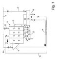
- the Fig. 1 shows a continuous washing machine with a drum 10 having only four chambers 18, 19 and 20.
- Two subsequent chambers 19 form the final wash zone 13, while the scavenger zone 14 in turn is formed by only one chamber 20 in the continuous washing machine shown.
- Both the two chambers 19 of the final wash zone 13 and the one chamber 20 of the rinse zone 14 have at the in Fig. 1 shown continuous washing machine each have their own outer drum 16.
- the circular walls of at least the chamber 20 of the rinsing zone 14 are formed straight and planar, namely in each case in a plane perpendicular to a longitudinal center axis of the drum 10 intersecting plane.
- the single chamber 20 of the rinse zone 14 is fed via a fresh water line 21 fresh water.
- the fresh water line 21 is opened and closed as required via a valve 22.
- All three outer drums 16 is associated with a drain line 23 which can be opened and closed by a valve 24.
- the outer drum 16 of the chamber 20 of the rinsing zone 14 has a second discharge line 25, which opens into a collecting tank 26. In this collection tank 26 may be intermediately stored after treatment liquid when it is needed again, namely about z. B. the fresh water line 21 of the chamber 20 of the rinse zone 14 should be fed again.
- the drain line 25 can be opened and closed by a valve 24 if necessary.
- the Fig. 2 shows a continuous washing machine, in which the prewashing zone 12 again has only one chamber 27, while the final wash zone 13 and the rinse zone 14 each have two chambers 28 and 29 with preferably flat and straight walls. Both the two chambers 28 of the final wash zone 13 and the two chambers 29 of the rinse zone 14 are assigned external drums 16 in the continuous washing machine shown here. Accordingly, only the single chamber 27 of the prewash zone 12 has no outer drum.
- each of the chambers 29 of the rinsing zone 14 can be supplied with fresh water.
- the fresh water supply to each chamber 29 is controlled by a valve 31.
- a drain line 32 branches off.
- the effluent through the drain line 32 treatment liquid enters an outflow.
- the drain line 32 under each outer drum 16 is required to open or close by a valve 33.
- a valve 33 is assigned in each case.
- the in the Fig. 3 shown continuous washing machine has seven consecutive chambers in the drum 10.
- the prewash zone 12 is formed of two chambers 36.
- the clear-wash zone 13 has two chambers 37.
- the rinsing zone 14 has three successive chambers 38, preferably with straight walls again, which lie in the longitudinal central axis of the drum 10 at right angles intersecting planes.
- the last chamber 36 of the prewash zone 12 and the first chamber 37 of the final wash zone 13 is associated with an outer drum 16.
- the first chamber 38 of the rinse zone 14 as well as the last (third) chamber 38 of the rinse zone 14 is associated with an outer drum 16.
- the middle chamber 38 of the rinsing zone 14 has no external drum 16 in the continuous washing machine shown here.
- fresh water can be fed to the first chamber 38 and the last chamber 38 of the rinsing zone 14, if required.
- All outer drums 16 open into drainage lines 42 which can be shut off by valves 41.
- Further outflow pipes 43 branch off from the outer drums 16 assigned to the two chambers 38 of the rinsing zone 14 and lead to a collecting tank 44.
- the drain lines 43 are each assigned a valve 55.
- the in the Fig. 4 The continuous washing machine shown has a total of twelve chambers in the drum 10.
- the three first chambers 46 form the prewash zone 12.
- Five consecutive chambers 47 form the final wash zone 13.
- Finally four chambers 48 are provided with preferably straight and even walls in the continuous washing machine shown here to form the rinsing zone 14.
- External drums 16 are in the continuous washing machine of Fig. 4 the last chamber 46 of Vorwaschzone 12, the first chamber 47 of the final wash zone 13 and the first chamber 48 and the last chamber 48 of the rinse zone 14 assigned.
- the two middle chambers 48 of the rinsing zone 14, no outer drum 16 is associated with the continuous washing machine shown.
- shut-off fresh water lines 50 are guided to the first and last chamber 48 of the rinse zone 14.
- a drain line 52 which can be shut off by valves 51 leads to a flushing water drain, for example a sewer.
- a further drain line 53 is preferably a storage tank. This also applies to all other embodiments.
- Each drain line 53 is associated with a valve.
- the in the Fig. 5 shown continuous washing machine has a total of thirteen chambers, which are accommodated successively in the common drum 10.
- the first three chambers 56 form the prewashing zone 12.
- Five subsequent chambers 57 are provided for the final wash zones 13.
- the rinse zone 14 is formed from five adjoining the final wash zone 13 chamber 58 again with preferably planar and straight walls.
- the last chamber 56 of the prewash zone 12 and the first chamber 57 of the final wash zone 13 is assigned an outer drum 16 in each case.
- three of the total of five chambers 58 for forming the rinse zone 14 have an outer drum 16.
- the first, the middle and the last chamber 58 of the rinse zone 14 each associated with an outer drum 16.
- the second and fourth chambers 58 of the washing zone 14 in the continuous washing machine shown here have no outer drum 16. It is so in the continuous washing machine of Fig. 5 each limited to a no outer drum 16 chamber 58 on both sides
- the middle, third chamber 58 has no outer drum 16 from a one outer drum 16 having chamber 58 of the rinse zone.
- the rinse zone 14 is formed by five chambers 58, wherein only the first and the last chamber 58 is associated with an outer drum 16.
- a drain line 61 branches off, which leads to a drainage channel. All drain lines 61 have a valve 62 which can be opened and closed as needed. From the three chambers 58 of the rinse zone 14 associated outer drums 16 branches off from each other by a valve 63 shut-off drain line 64, which leads to a collection tank 65.
- the collection tanks 26, 35, 44, 54 and 65 also receive the liquid of the bound and / or free liquor removed from the washed laundry by the dewatering device 66 following from the continuous washing machine. Furthermore, leads into the collection tank 26, 35, 44, 54 and 65 a closable by a valve fresh water line 67. Another shut off a valve fresh water line leads to the input hopper 17 in front of the drum 10 of the respective continuous washing machine. From the collection tank 26, 35, 44, 54 and 65 can be pumped to the input hopper 17 via a supply line 69 which can be shut off from a valve supply liquid. This can be done mixing with fresh water.
- valve supply line 70 leads from the collection tank 26, 35, 44, 54 and 65 either to the last chamber of Vorwaschzone 12 or the first chamber of the final wash zone 13.
- the inventive method is characterized in particular for the previously described embodiments of continuous washing machines in that at least one bath change in the rinse zone 14 is made.
- a bath change always takes place in such chambers 20, 29, 38, 48 and 58 of the rinse zone 14, which an outer drum 16 is associated.
- the at least one bath change takes place in at least some chambers 20, 29, 38, 48 and 58 of the rinsing zone 14 independently of other chambers 20, 29, 38, 48 and 58, respectively.
- the bath change can be targeted in any chambers 20, 29, 38, 48 and 58, respectively.
- rinsing contaminated treatment liquid namely rinsing liquid
- the laundry is largely separated from the treatment liquid, namely rinsing liquid.
- the rinsing liquid, the free liquor, which is not bound in the laundry, is preferably completely released from those chambers 20, 29, 38, 48 and 58, to which an external drum 16 is assigned.
- the free liquor can either be directed to the drain or cached in the collection tank 26, 35, 44, 54 and 65, respectively.
- the respective chamber 20, 29, 38, 48 and 58 After draining the rinsing liquid, the respective chamber 20, 29, 38, 48 and 58 again to the intended level with fresh water from the fresh water line 21, 30, 40, 50 or 60 or liquid from the collection tank 26, 35, 44, 54 or 65 filled.
- This draining of rinse water and filling with fresh water preferably forms the so-called bath change.
- the rinsing zone 14 may also take place a post-treatment of the laundry, preferably an equipping, but also a bleaching, neutralizing and / or starches.
- This chamber 20, 29, 38, 48 and 58, respectively can only be used for aftertreatment or for rinsing and subsequent aftertreatment.
- the fresh water is supplied with aftertreatment agent.
- the aftertreatment liquid is cached after completion of the aftertreatment in the collection tank 26, 35, 44, 54 and 65 and reused at least once.
- not all chambers 20, 29, 38, 48, 58 of the rinsing zone 14 are assigned an outer drum 16. Only those chambers 20, 29, 38, 48, 58 of the rinsing zone 14, in which a bath change takes place, an outer drum 16 is assigned. In this way, not every chamber 20, 29, 38, 48, 58 of the rinsing zone 14 needs to be assigned to an outer drum 16.
- the laundry from the last chamber 19 of the final wash zone 13 with the entire liquor into the chamber 20 of the rinse zone 14 at least the entire free liquor, ie the final wash liquid, is first drained via the outer drum 16 and then introduced fresh water into the chamber 20. It then takes the rinsing of the laundry. After rinsing, the rinse water can be drained off and refilled with fresh water, to which an aftertreatment agent, for example a finishing agent, is then added. It then takes place in the chamber 20 of the rinse zone 14, the aftertreatment (for example, equipment) of the laundry. The after-treatment may be omitted if necessary.
- the laundry with the entire fleet and although preferably also the free liquor discharged through the discharge chute 15 from the drum 10 and thus discharged the finished treated laundry items from the continuous washing machine.
- the dewatering device 66 is then a drainage of the laundry of the entire laundry costs.
- the inventive method runs with the continuous washing machine of Fig. 4 in the rinsing zone 14 in principle just as from the previously in connection with the continuous washing machine of Fig. 3 described method in the rinsing zone 14th
- the Fig. 4 four chambers 48 for forming the rinsing zone 14, of which the two central chambers 48 no outer drum 16 is assigned, takes place in the second and third chamber 48 no change of bath instead. Accordingly, in the second and third chambers 28 of the rinsing zone 14, the washing is rinsed with the rinsing liquid from the first chamber 48 of the rinsing zone 14, that is the rinsing liquid from the first chamber 48 with the laundry into the second chamber 48 and then into the third chamber 48 of the rinse zone 14 loaded.
- a first bath change takes place in the first chamber 58 of the rinse zone 14.
- no bath change takes place.
- Only in the third chamber 58 of the rinse zone 14 is again a bath change.
- no bath change is provided in the fourth chamber 58.
- At least one last bath change takes place in the last (fifth) chamber 58 of the rinsing zone 14. This can be done for rinsing or even for after-treatment. It is also conceivable, however, in the last chamber 58 of the rinsing zone 14 first to rinse the items of laundry and then to post-treat.
- the continuous washing machines according to the invention and the method according to the invention offer a multiplicity of advantages over conventional continuous washing machines in which the rinsing of the laundry in the rinsing zone takes place in countercurrent.
- a better dilution can be achieved, resulting in a more advantageous dishwashing result.
- the use of fresh water is thereby reduced, as well as the possibly required acid use to neutralize the laundry.
- every batch of laundry in its chamber receives an exact amount of water, which makes the rinsing process precisely controllable and reproducible.
- laundry parts of different colors and also coloreds and white laundry can be rinsed in successive chambers, without intervening empty chambers are required as before.
- the invention leads to an overall shorter throughput washing machines with a comparatively smaller number of chambers.
- the invention enables a faster bath change and a better wash result, which corresponds to that of a washer-extractor. There are several bath changes, if necessary in a chamber possible, creating a better dirt and Flusenaustragung is possible. Finally, it is possible to perform the rinsing, the finishing, the neutralizing and other post-treatments of the laundry in the same rinsing chamber, even if the continuous washing machine has only a single rinsing chamber.
- the inventive method is not on continuous washing machines of the embodiments shown the Fig. 1 to 5 limited. Rather, the inventive method is basically suitable for all continuous washing machines with any number and arbitrary arrangement of the successive chambers.
- the number of chambers of the rinse zone 14 may be arbitrary.
- the division of the chambers of the rinse zone 14 in those that allow a bath change due to an outer drum 16 and those that have no outer drums 16 and thus do not allow Bad , be arbitrary.
Landscapes
- Engineering & Computer Science (AREA)
- Textile Engineering (AREA)
- Accessory Of Washing/Drying Machine, Commercial Washing/Drying Machine, Other Washing/Drying Machine (AREA)
- Detail Structures Of Washing Machines And Dryers (AREA)
- Treatment Of Fiber Materials (AREA)
Claims (13)
- Procédé de traitement en conditions humides de linge dans une machine de lavage continu qui présente un tambour (10) entraîné en rotation et doté de plusieurs chambres successives (18, 19, 20; 27, 28, 29; 36, 37, 38; 46, 47, 48; 56, 57, 58), et dans laquelle le linge est transporté et lavé, rincé et éventuellement post-traité dans le sens de la longueur du tambour (10) en traversant les chambres successives (18, 19, 20; 27, 28, 29; 36, 37, 38; 46, 47, 48; 56, 57, 58) d'une zone de prélavage (12), d'une zone de lavage (13) et d'une zone de rinçage (14), au moins un changement de bain étant réalisé dans la zone de rinçage (14),
caractérisé en ce que
au moins un tambour extérieur (16) est associé à une seule chambre (20, 29, 38, 48, 58) ou à seulement une partie des chambres (20, 29, 38, 48, 58) de la zone de lavage (14) et
en ce qu'un changement de bain est réalisé uniquement dans les chambres (20, 29, 38, 48, 58) de la zone de rinçage (14) auxquelles le ou les tambours extérieurs (16) sont associés. - Procédé selon la revendication 1, caractérisé en ce qu'au moins un changement de bain est réalisé dans la zone de rinçage (14) qui sert au rinçage et éventuellement aussi au post-traitement, par évacuation et amenée de liquide de traitement, et en ce que lorsque la zone de rinçage (14) présente plusieurs chambres (20, 29, 38, 48, 58), un changement de bain est réalisé de préférence dans toutes ou au moins certaines chambres sélectionnées de la zone de rinçage (14), indépendamment les unes des autres.
- Procédé selon les revendications 1 ou 2, caractérisé en ce que pour le changement de bain et de préférence pour chaque changement de bain, le liquide de traitement utilisé pour le rinçage ou le post-traitement est évacué et remplacé par le liquide de traitement frais et en particulier de l'eau fraîche.
- Procédé selon l'une des revendications précédentes, caractérisé en ce que pour le changement de bain, le liquide de traitement et de préférence au moins le liquide libre est séparé du linge de préférence complètement, et en cas de besoin, plusieurs changements de bain sont réalisés de préférence dans les mêmes chambres (20, 29, 38, 48, 58) qui servent au rinçage ou au rinçage et/ou au post-traitement.
- Procédé selon l'une des revendications précédentes, caractérisé en ce l'évacuation et l'amenée de liquide de traitement (changement de bain) s'effectuent dans la même chambre (20, 29, 38, 48, 58).
- Procédé selon l'une des revendications précédentes, caractérisé en ce que l'évacuation du liquide de traitement utilisé pour le rinçage s'effectue dans la chambre (20, 29, 38, 48, 58) dans laquelle le rinçage a été effectué avec le liquide de traitement et le linge est transporté dans la chambre (20, 29, 38, 48, 58) suivante sans le liquide de traitement utilisé pour le rinçage, dans laquelle un autre liquide de traitement, de préférence de l'eau fraîche, est ajouté au linge.
- Procédé selon l'une des revendications précédentes, caractérisé en ce que dans au moins une chambre (20, 29, 38, 48, 58) dans laquelle aucun changement de bain n'a lieu, le rinçage est réalisé avec du liquide de traitement et en particulier du liquide de rinçage provenant de la chambre (20, 29, 38, 48, 58) dans laquelle un changement de bain a été effectué en dernier lieu.
- Procédé selon l'une des revendications précédentes, caractérisé en ce qu'au début du rinçage dans la première chambre (20, 29, 38, 48, 58) de la zone de rinçage (14), un premier changement de bain a lieu.
- Procédé selon l'une des revendications précédentes, caractérisé en ce qu'au moins une partie d'un changement de bain est réalisée dans une zone de lavage (13), de préférence par évacuation du liquide de lavage dans la dernière chambre (19, 28) de la zone de lavage (13).
- Dispositif de traitement en conditions humides de linge, le dispositif présentant un tambour (10) entraîné en rotation dans lequel une zone de prélavage (12), une zone de lavage (13) et une zone de rinçage (14) servant éventuellement aussi à un post-traitement sont formées par des chambres (18, 19, 20; 27, 28, 29; 36, 37, 38; 46, 47, 48; 56, 57, 58) successives, caractérisé en ce que
un tambour extérieur (16) est associé à seulement une partie des chambres (20, 29, 38, 48, 58) de la zone de rinçage (14),
en ce que le tambour extérieur (16) est configuré pour permettre un changement de bain dans la chambre (20, 29, 38, 48, 58) concernée et
en ce qu'au niveau de la chambre (20, 29, 38, 48, 58) ou des chambres (20, 29, 38, 48, 58) à laquelle ou auxquelles aucun tambour extérieur (16) n'est associé, le tambour (10) dispose d'une partie d'enveloppe imperméable aux liquides. - Dispositif selon la revendication 10, caractérisé en ce que la zone de rinçage (14) est formée de plusieurs chambres (20, 29, 38, 48, 58), la zone de rinçage (14) présentant de préférence au moins deux chambres (20, 29, 38, 48, 58) qui permettent un changement de bain.
- Dispositif selon les revendications 10 ou 11, caractérisé en ce que le tambour (10) n'est doté d'un tambour extérieur (16) qu'au niveau des chambres (20, 29, 38, 48, 58) qui permettent un changement de bain de la zone de rinçage (14), est configuré de manière à être perméable aux liquides.
- Dispositif selon l'une des revendications précédentes, caractérisé en ce que les parois des chambres (20, 29, 38, 48, 58) d'au moins la zone de rinçage (14) ont une surface plane, les parois à surface plane étant situées dans un plan qui coupe à la perpendiculaire l'axe longitudinal du tambour (10).
Applications Claiming Priority (2)
| Application Number | Priority Date | Filing Date | Title |
|---|---|---|---|
| DE200610009553 DE102006009553A1 (de) | 2006-02-28 | 2006-02-28 | Verfahren und Vorrrichtung zum Nassbehandeln von Wäsche |
| PCT/EP2007/001414 WO2007098871A1 (fr) | 2006-02-28 | 2007-02-19 | Procédé et dispositif de traitement du linge par voie humide |
Publications (2)
| Publication Number | Publication Date |
|---|---|
| EP1989349A1 EP1989349A1 (fr) | 2008-11-12 |
| EP1989349B1 true EP1989349B1 (fr) | 2014-12-17 |
Family
ID=38266235
Family Applications (1)
| Application Number | Title | Priority Date | Filing Date |
|---|---|---|---|
| EP07722850.0A Not-in-force EP1989349B1 (fr) | 2006-02-28 | 2007-02-19 | Procédé et dispositif de traitement du linge par voie humide |
Country Status (4)
| Country | Link |
|---|---|
| EP (1) | EP1989349B1 (fr) |
| DE (1) | DE102006009553A1 (fr) |
| ES (1) | ES2532460T3 (fr) |
| WO (1) | WO2007098871A1 (fr) |
Families Citing this family (2)
| Publication number | Priority date | Publication date | Assignee | Title |
|---|---|---|---|---|
| ES2874474T3 (es) | 2012-08-20 | 2021-11-05 | Pellerin Corp Milnor | Método de lavado de artículos de tela en una lavadora de túnel |
| EP3216907A1 (fr) * | 2016-03-09 | 2017-09-13 | Herbert Kannegiesser GmbH | Procédé de traitement par voie humide de linge |
Family Cites Families (1)
| Publication number | Priority date | Publication date | Assignee | Title |
|---|---|---|---|---|
| CA1182299A (fr) * | 1981-04-17 | 1985-02-12 | Norvin L. Pellerin | Lessiveuse continue, et mode de fonctionnement connexe |
-
2006
- 2006-02-28 DE DE200610009553 patent/DE102006009553A1/de not_active Withdrawn
-
2007
- 2007-02-19 ES ES07722850.0T patent/ES2532460T3/es active Active
- 2007-02-19 WO PCT/EP2007/001414 patent/WO2007098871A1/fr active Application Filing
- 2007-02-19 EP EP07722850.0A patent/EP1989349B1/fr not_active Not-in-force
Also Published As
| Publication number | Publication date |
|---|---|
| EP1989349A1 (fr) | 2008-11-12 |
| ES2532460T3 (es) | 2015-03-27 |
| DE102006009553A1 (de) | 2007-08-30 |
| WO2007098871A1 (fr) | 2007-09-07 |
Similar Documents
| Publication | Publication Date | Title |
|---|---|---|
| EP0088052B1 (fr) | Procédé pour laver du linge et machine à laver en continu pour la mise en oeuvre du procédé | |
| EP1184504B1 (fr) | Procédé pour laver le linge dans une machine à laver en continu sans réservoir et machine à laver utilisant un tel procédé | |
| EP1236823B1 (fr) | Procédé pour le traitement au mouillé du linge | |
| DE19608030C1 (de) | Reinigungsmaschine, insbesondere für Geschirr | |
| DE10035904B4 (de) | Vorrichtung zur Nassbehandlung von Wäsche | |
| EP1983087B1 (fr) | Procédé destinés au traitement humide de pièces de linge | |
| EP1848851B1 (fr) | Procede et dispositif pour le traitement par voie humide de pieces de linge | |
| DE3709332A1 (de) | Postenwaschmaschine | |
| EP1995364B1 (fr) | Procédé de traitement humide de pièces de linge | |
| EP1989349B1 (fr) | Procédé et dispositif de traitement du linge par voie humide | |
| DE2825853A1 (de) | Waschanordnung | |
| DE3881020T2 (de) | Trommel waschmaschine. | |
| WO1995002722A1 (fr) | Tunnel de lavage et procede d'acheminement d'eau | |
| DE10162800A1 (de) | Badwechselmaschine und Verfahren zum Betreiben derselben | |
| DE10031040B4 (de) | Verfahren und Vorrichtung zur Naßbehandlung von Wäschestücken | |
| EP1997948B1 (fr) | Procédé de traitement humide de pièces de linge | |
| DE10105820B4 (de) | Verfahren zum Waschen von insbesondere Wäschestücken | |
| DE102010050489A1 (de) | Verfahren und Vorrichtung zur Nassbehandlung, insbesondere zum Waschen, von Wäschestücken | |
| DE10031038B4 (de) | Verfahren zum Abscheiden von Verunreinigungen aus einer Flüssigkeit zum Waschen von Wäsche in einer Durchlaufwaschmaschine | |
| DE102005053085B4 (de) | Verfahren und Vorrichtung zur Nassbehandlung von Wäschestücken | |
| DE102012109839B4 (de) | Waschmaschinensystem und Verfahren zum Betrieb eines Waschmaschinensystems | |
| DE4323963A1 (de) | Verfahren, Vorrichtung und Anlage zum Waschen von Matratzen, insbesondere Schaumstoffmatratzen | |
| DE10130990B4 (de) | Gegenstromwaschmaschine | |
| EP3216907A1 (fr) | Procédé de traitement par voie humide de linge | |
| AT258843B (de) | Stirnbeschickte rohrförmige Doppeltrommel-Durchlaufwaschmaschine |
Legal Events
| Date | Code | Title | Description |
|---|---|---|---|
| PUAI | Public reference made under article 153(3) epc to a published international application that has entered the european phase |
Free format text: ORIGINAL CODE: 0009012 |
|
| 17P | Request for examination filed |
Effective date: 20080715 |
|
| AK | Designated contracting states |
Kind code of ref document: A1 Designated state(s): DE ES FR GB IT |
|
| DAX | Request for extension of the european patent (deleted) | ||
| RBV | Designated contracting states (corrected) |
Designated state(s): DE ES FR GB IT |
|
| 17Q | First examination report despatched |
Effective date: 20120823 |
|
| GRAP | Despatch of communication of intention to grant a patent |
Free format text: ORIGINAL CODE: EPIDOSNIGR1 |
|
| INTG | Intention to grant announced |
Effective date: 20140806 |
|
| GRAS | Grant fee paid |
Free format text: ORIGINAL CODE: EPIDOSNIGR3 |
|
| GRAA | (expected) grant |
Free format text: ORIGINAL CODE: 0009210 |
|
| AK | Designated contracting states |
Kind code of ref document: B1 Designated state(s): DE ES FR GB IT |
|
| REG | Reference to a national code |
Ref country code: GB Ref legal event code: FG4D Free format text: NOT ENGLISH |
|
| REG | Reference to a national code |
Ref country code: DE Ref legal event code: R096 Ref document number: 502007013632 Country of ref document: DE Effective date: 20150212 |
|
| REG | Reference to a national code |
Ref country code: ES Ref legal event code: FG2A Ref document number: 2532460 Country of ref document: ES Kind code of ref document: T3 Effective date: 20150327 |
|
| PGFP | Annual fee paid to national office [announced via postgrant information from national office to epo] |
Ref country code: GB Payment date: 20150304 Year of fee payment: 9 |
|
| REG | Reference to a national code |
Ref country code: DE Ref legal event code: R097 Ref document number: 502007013632 Country of ref document: DE |
|
| PLBE | No opposition filed within time limit |
Free format text: ORIGINAL CODE: 0009261 |
|
| STAA | Information on the status of an ep patent application or granted ep patent |
Free format text: STATUS: NO OPPOSITION FILED WITHIN TIME LIMIT |
|
| 26N | No opposition filed |
Effective date: 20150918 |
|
| PG25 | Lapsed in a contracting state [announced via postgrant information from national office to epo] |
Ref country code: IT Free format text: LAPSE BECAUSE OF FAILURE TO SUBMIT A TRANSLATION OF THE DESCRIPTION OR TO PAY THE FEE WITHIN THE PRESCRIBED TIME-LIMIT Effective date: 20141217 |
|
| REG | Reference to a national code |
Ref country code: FR Ref legal event code: PLFP Year of fee payment: 10 |
|
| GBPC | Gb: european patent ceased through non-payment of renewal fee |
Effective date: 20160219 |
|
| PG25 | Lapsed in a contracting state [announced via postgrant information from national office to epo] |
Ref country code: GB Free format text: LAPSE BECAUSE OF NON-PAYMENT OF DUE FEES Effective date: 20160219 |
|
| REG | Reference to a national code |
Ref country code: FR Ref legal event code: PLFP Year of fee payment: 11 |
|
| REG | Reference to a national code |
Ref country code: FR Ref legal event code: PLFP Year of fee payment: 12 |
|
| PGFP | Annual fee paid to national office [announced via postgrant information from national office to epo] |
Ref country code: ES Payment date: 20200302 Year of fee payment: 14 Ref country code: DE Payment date: 20200130 Year of fee payment: 14 |
|
| PGFP | Annual fee paid to national office [announced via postgrant information from national office to epo] |
Ref country code: FR Payment date: 20200127 Year of fee payment: 14 |
|
| REG | Reference to a national code |
Ref country code: DE Ref legal event code: R119 Ref document number: 502007013632 Country of ref document: DE |
|
| PG25 | Lapsed in a contracting state [announced via postgrant information from national office to epo] |
Ref country code: FR Free format text: LAPSE BECAUSE OF NON-PAYMENT OF DUE FEES Effective date: 20210228 Ref country code: DE Free format text: LAPSE BECAUSE OF NON-PAYMENT OF DUE FEES Effective date: 20210901 |
|
| REG | Reference to a national code |
Ref country code: ES Ref legal event code: FD2A Effective date: 20220513 |
|
| PG25 | Lapsed in a contracting state [announced via postgrant information from national office to epo] |
Ref country code: ES Free format text: LAPSE BECAUSE OF NON-PAYMENT OF DUE FEES Effective date: 20210220 |