EP1988248A2 - Boîtier d'étanchéité et joint doté de profilés d'étanchéité latéraux - Google Patents
Boîtier d'étanchéité et joint doté de profilés d'étanchéité latéraux Download PDFInfo
- Publication number
- EP1988248A2 EP1988248A2 EP08007444A EP08007444A EP1988248A2 EP 1988248 A2 EP1988248 A2 EP 1988248A2 EP 08007444 A EP08007444 A EP 08007444A EP 08007444 A EP08007444 A EP 08007444A EP 1988248 A2 EP1988248 A2 EP 1988248A2
- Authority
- EP
- European Patent Office
- Prior art keywords
- seal
- housing
- groove
- door
- housing part
- Prior art date
- Legal status (The legal status is an assumption and is not a legal conclusion. Google has not performed a legal analysis and makes no representation as to the accuracy of the status listed.)
- Withdrawn
Links
- 238000007789 sealing Methods 0.000 claims abstract description 53
- XAGFODPZIPBFFR-UHFFFAOYSA-N aluminium Chemical compound [Al] XAGFODPZIPBFFR-UHFFFAOYSA-N 0.000 claims description 2
- 229910052782 aluminium Inorganic materials 0.000 claims description 2
- 229920001971 elastomer Polymers 0.000 claims description 2
- 239000000806 elastomer Substances 0.000 claims description 2
- 239000006260 foam Substances 0.000 claims description 2
- 238000000034 method Methods 0.000 claims description 2
- 238000004026 adhesive bonding Methods 0.000 claims 1
- 239000000779 smoke Substances 0.000 description 5
- 239000002023 wood Substances 0.000 description 5
- 239000007787 solid Substances 0.000 description 2
- 238000003780 insertion Methods 0.000 description 1
- 230000037431 insertion Effects 0.000 description 1
- 238000003801 milling Methods 0.000 description 1
- 230000035515 penetration Effects 0.000 description 1
- 230000001960 triggered effect Effects 0.000 description 1
Images


Classifications
-
- E—FIXED CONSTRUCTIONS
- E06—DOORS, WINDOWS, SHUTTERS, OR ROLLER BLINDS IN GENERAL; LADDERS
- E06B—FIXED OR MOVABLE CLOSURES FOR OPENINGS IN BUILDINGS, VEHICLES, FENCES OR LIKE ENCLOSURES IN GENERAL, e.g. DOORS, WINDOWS, BLINDS, GATES
- E06B7/00—Special arrangements or measures in connection with doors or windows
- E06B7/16—Sealing arrangements on wings or parts co-operating with the wings
- E06B7/18—Sealing arrangements on wings or parts co-operating with the wings by means of movable edgings, e.g. draught sealings additionally used for bolting, e.g. by spring force or with operating lever
- E06B7/20—Sealing arrangements on wings or parts co-operating with the wings by means of movable edgings, e.g. draught sealings additionally used for bolting, e.g. by spring force or with operating lever automatically withdrawn when the wing is opened, e.g. by means of magnetic attraction, a pin or an inclined surface, especially for sills
- E06B7/215—Sealing arrangements on wings or parts co-operating with the wings by means of movable edgings, e.g. draught sealings additionally used for bolting, e.g. by spring force or with operating lever automatically withdrawn when the wing is opened, e.g. by means of magnetic attraction, a pin or an inclined surface, especially for sills with sealing strip being moved to a retracted position by elastic means, e.g. springs
Definitions
- the invention relates to a seal housing for a self-releasing when closing a door or a window seal for mounting in a groove of a door leaf or window sash, with a housing part having a longitudinal slot for arranging a movable sealing profile of the seal.
- the invention further relates to a gasket for mounting in a groove of a door leaf of a window or window sash of a window, the gasket being suitable and adapted to be automatically triggered and lowered when closing a door or a window, the gasket having a gasket housing.
- the invention also relates to an arrangement of a door leaf for a door with a groove and with a seal, wherein in the groove the self-releasing when closing the door seal is arranged.
- seals are used with self-closing when closing the door lowerable sealing profiles in front doors, apartment doors and interior doors to prevent drafts, noise and / or smoke entering.
- Such a seal with an automatically lowerable sealing profile is for example from the patent specification with the publication number EP 1 460 232 B1 known.
- the seal disclosed in this patent like many other seals, is inserted in a groove at the bottom of the door leaf.
- the groove is milled into the wood. Due to humidity or due to other influences, the door may deform in the area of the groove. For example, the phenomenon of so-called "chipping" of the groove is known.
- “Chipping” is when the wood deforms in the region of the groove so that the groove has a smaller width in the region of the opening than in the groove bottom. It is also known that the doors are curved at the ends provided with the groove in the axial direction of the groove deform. These types of deformations hinder or prevent the insertion of a seal in the groove. It is therefore currently common practice that the grooves in the lower ends of the door wings are milled wider than would be necessary according to the outer dimensions of the gasket. It is then possible despite the deformations in the region of the wood in the region of the groove to insert the seal in the groove. It goes without saying that the wood can then deform only in the tolerance range which is predetermined by the larger cut-out of the groove on the outer dimensions of the seal.
- the invention was based on the background of the described disadvantage of the prior art, the object of a seal housing, a seal and an arrangement of a door and a gasket so evolve that a draft or a sound or smoke through the gap between the seal and the walls of the groove is not possible.
- This object is achieved in that arranged on one or more outer sides of the housing part of the seal housing in the longitudinal direction extending lateral sealing profiles which are suitable and adapted to seal a resulting after assembly of the seal in the groove between the outer sides of the housing air gap , These lateral sealing profiles apply to the walls of the groove.
- lateral sealing profiles apply to the walls of the groove.
- An advantage of such a seal is that this seal is removable and reassemblable at any time, without having to worry about a new seal of the gap between the walls of the groove and the seal housing, since the lateral sealing profiles readily provide for resealing.
- the lateral sealing profiles of a seal according to the invention after the assembly of the seals in doors can compensate for changes in the gap dimensions, without causing leaks.
- the seal housing according to the invention can be designed so that the lateral sealing profiles are connected by positive engagement with the housing part of the seal housing.
- the sealing profiles can be clipped into the housing part, for example. It is also possible that the lateral sealing profiles are glued to the housing part. It is also conceivable that the sealing profiles are extruded together with the housing part or portions of the housing part in the two-component method. This is particularly useful when both the lateral sealing profiles and the housing part made of plastic or at least partially made of plastic.
- the housing part may consist entirely or partially of aluminum and / or plastic.
- the lateral sealing profiles are preferably made of an elastomer.
- they can be made of foam.
- Two or more lateral sealing profiles of a seal housing according to the invention may be connected to one another.
- the side sealing profiles can also consist of a single piece.
- the sealing profiles may be hollow profiles or sealing lips.
- An inventive seal housing forms together with the other known components, such as the sealing strip and the mechanism for automatically lifting the sealing strip a seal according to the invention.
- a seal according to the invention may comprise mounting brackets which are suitable and adapted for fastening the seal to a door leaf.
- the seal comprises fastening means, which are arranged captive on the seal housing in the groove of the door leaf before mounting the seal.
- Such a seal according to the invention together with a door leaf for a door, forms an arrangement according to the invention.
- the depth of the groove may be greater than the height of the housing part of the seal housing of the seal. If this is the case, the seal can be mounted in the groove base. It is also possible that the seal housing is finally mounted with the edge of the groove. Of course, any assembly in a position between the position of the seal housing in the groove base or at the groove edge is possible.
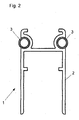
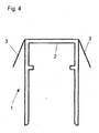
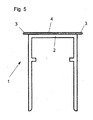
- FIGS. 1 to 5 illustrated sealing housing 1 have a housing part 2 and two attached thereto lateral sealing profiles 3.
- the housing parts 2 are in the seal housings 1 according to the Fig. 1 . 4 and 5 identically formed.
- the housing parts are made of a cross-sectionally substantially U-shaped profile. On the inside of the mutually parallel legs each opposite a collar is formed, which serves to receive a movable sealing strip and the movable sealing strip and the housing part 2 connecting mechanism.
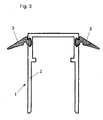
- the housing parts 2 of the seal housing 1 according to the Fig. 2 and 3 differ from the housing parts 2 of the seal housing 1 according to the FIGS. 1 . 4 and 5 in that on the housing parts 2 according to the Figures 2 and 3 Holding structures for the positive attachment of the lateral sealing profiles 3 has.
- Fig. 3 are undercut channels formed in the outer sides of the legs of the housing part 2, in which the lateral sealing profiles 3 are clipped or retracted with corresponding support structures.
- the two lateral sealing profiles 3 are integrally connected to each other via a web 4.
- the lateral sealing profiles 3 of the seal housing 1, as shown in the Fig. 1 to 5 are shown is common that they protrude laterally beyond the housing part 2. Thus, they are suitable and adapted to seal an air gap between the outer sides of the legs of the housing parts 2 and the side walls of a groove in a door, so as to allow the passage of air, smoke and / or sound from one side of the door through this air gap on the prevent other side of the door.
- the lateral sealing profiles 3 are deformed after dem.EinTERa the seal in a groove of the door leaf, as in particular in comparison with the example of Fig. 6 is recognizable.
- the Fig. 6 shows the sealing of the air gap through the lateral sealing profiles 3 relative to the lateral wall of the groove 9 of the door leaf 5.
- a sealing strip is arranged, which is connected via a conventional mechanism with the housing part 2 of the seal housing 1.
- the sealing strip is automatically lowered over the mechanism when closing the door and automatically raised when the door is opened. Wear the sealing strips a total of three sealing profiles, the seal in the closed state of the door between the lower end of the door leaf 5 and the floor or between the upper end of the door leaf 5 and a frame or ceiling remaining gap.
- the seal housing 1 corresponds to the in Fig. 4 shown seal housing 1 largely.
Landscapes
- Engineering & Computer Science (AREA)
- Civil Engineering (AREA)
- Structural Engineering (AREA)
- Specific Sealing Or Ventilating Devices For Doors And Windows (AREA)
Applications Claiming Priority (1)
| Application Number | Priority Date | Filing Date | Title |
|---|---|---|---|
| DE200720006336 DE202007006336U1 (de) | 2007-05-03 | 2007-05-03 | Dichtungsgehäuse und Dichtung mit seitlichen Dichtungsprofilen |
Publications (2)
| Publication Number | Publication Date |
|---|---|
| EP1988248A2 true EP1988248A2 (fr) | 2008-11-05 |
| EP1988248A3 EP1988248A3 (fr) | 2010-12-22 |
Family
ID=38375414
Family Applications (1)
| Application Number | Title | Priority Date | Filing Date |
|---|---|---|---|
| EP08007444A Withdrawn EP1988248A3 (fr) | 2007-05-03 | 2008-04-16 | Boîtier d'étanchéité et joint doté de profilés d'étanchéité latéraux |
Country Status (2)
| Country | Link |
|---|---|
| EP (1) | EP1988248A3 (fr) |
| DE (1) | DE202007006336U1 (fr) |
Cited By (1)
| Publication number | Priority date | Publication date | Assignee | Title |
|---|---|---|---|---|
| EP2554774A1 (fr) | 2011-08-02 | 2013-02-06 | Planet GDZ AG | Joint pour une porte sans seuil |
Families Citing this family (2)
| Publication number | Priority date | Publication date | Assignee | Title |
|---|---|---|---|---|
| IT1393882B1 (it) * | 2009-04-29 | 2012-05-11 | Geron | Assieme di fissaggio per guarnizioni |
| NL2012920B1 (nl) * | 2014-05-30 | 2016-06-09 | Elton Bv | Deurafdichting, deur met deurafdichting en werkwijze voor het vervaardigen daarvan. |
Citations (1)
| Publication number | Priority date | Publication date | Assignee | Title |
|---|---|---|---|---|
| EP1460232B1 (fr) | 2003-03-19 | 2006-08-23 | Manfred Kross | Dispositif d'étanchéité de sol dans une porte |
Family Cites Families (2)
| Publication number | Priority date | Publication date | Assignee | Title |
|---|---|---|---|---|
| DE3237524C2 (de) * | 1982-10-09 | 1986-08-07 | Fa. F. Athmer, 5760 Arnsberg | Fußbodenseitige Türdichtungsvorrichtung |
| PL1627126T3 (pl) * | 2003-05-08 | 2012-09-28 | Roto Gluske Bkv Gmbh | Uszczelnienie przypodłogowe wyposażone w taśmę sprężystą |
-
2007
- 2007-05-03 DE DE200720006336 patent/DE202007006336U1/de not_active Expired - Lifetime
-
2008
- 2008-04-16 EP EP08007444A patent/EP1988248A3/fr not_active Withdrawn
Patent Citations (1)
| Publication number | Priority date | Publication date | Assignee | Title |
|---|---|---|---|---|
| EP1460232B1 (fr) | 2003-03-19 | 2006-08-23 | Manfred Kross | Dispositif d'étanchéité de sol dans une porte |
Cited By (3)
| Publication number | Priority date | Publication date | Assignee | Title |
|---|---|---|---|---|
| EP2554774A1 (fr) | 2011-08-02 | 2013-02-06 | Planet GDZ AG | Joint pour une porte sans seuil |
| EP2840221A1 (fr) | 2011-08-02 | 2015-02-25 | Planet GDZ AG | Joint pour une porte sans seuil |
| EP2843176A1 (fr) | 2011-08-02 | 2015-03-04 | Planet GDZ AG | Joint pour une porte sans seuil |
Also Published As
| Publication number | Publication date |
|---|---|
| EP1988248A3 (fr) | 2010-12-22 |
| DE202007006336U1 (de) | 2007-08-16 |
Similar Documents
| Publication | Publication Date | Title |
|---|---|---|
| EP2921634B1 (fr) | Joint pour portes pour étanchéifier un passage d'air entre un battant de porte d'une part et un cadre de porte, un sol, un plafond, un linteau d'autre part | |
| EP1936097B1 (fr) | Système de joint de porte | |
| EP3259428B1 (fr) | Dispositif d'étanchéité pour éléments de fenêtre et éléments de porte | |
| EP2824270A1 (fr) | Élément de surface d'une verrière ignifuge, notamment porte en verre pour des applications anti-incendie pour éviter le passage du feu et de la fumée d'une pièce à une autre en cas d'incendie | |
| DE102006005610B4 (de) | Insektenschutzrahmen | |
| EP2088275B1 (fr) | Profilé d'étanchéité de côtés, notamment pour profilés de cadre et installations de portes coulissantes en étant équipées | |
| DE1509553A1 (de) | Fensterkonstruktion | |
| EP3165701A1 (fr) | Élément d'aération pour fenêtre comprenant un clapet agissant comme une chicane | |
| EP1988248A2 (fr) | Boîtier d'étanchéité et joint doté de profilés d'étanchéité latéraux | |
| EP1863999B1 (fr) | Battant d'une porte ou d'une fenetre | |
| EP3019684B1 (fr) | Système de joint d'une porte | |
| DE10207157B4 (de) | Verbindungselement zur stirnseitigen Verbindung von zwei Teilen | |
| CH711428B1 (de) | Modulares System für Schränke und/oder Regale. | |
| EP2666952B1 (fr) | Profil d'étanchéité pour joint de porte ou de fenêtre | |
| DE102022206444B4 (de) | Blendrahmen für eine Tür mit Extrusionsrahmen und Schwelle, Tür mit einem derartigen Blendrahmen und Verfahren zur Herstellung dieser Tür | |
| EP2060726A2 (fr) | Profilé creux | |
| DE102011008765A1 (de) | Profilanordnung, Rahmen und Rahmenanordnung | |
| AT510431B1 (de) | Blindzarge | |
| DE202016100768U1 (de) | Profil für Fenster- und Türrahmen | |
| DE19753638C2 (de) | Blend- oder Flügelrahmen für Fenster oder Türen | |
| DE102015102582B3 (de) | Vorsatztür oder -fenster, insbesondere Insektenschutztür oder -fenster | |
| EP4345239A1 (fr) | Cadre pour border au moins une vitre et dispositif comprenant le cadre et un cadre | |
| DE10322029B4 (de) | Profilsystem | |
| DE2541040A1 (de) | Schaukasten | |
| DE102018127667A1 (de) | Türband für eine Duschabtrennung und eine Duschabtrennung mit einem Türband |
Legal Events
| Date | Code | Title | Description |
|---|---|---|---|
| PUAI | Public reference made under article 153(3) epc to a published international application that has entered the european phase |
Free format text: ORIGINAL CODE: 0009012 |
|
| AK | Designated contracting states |
Kind code of ref document: A2 Designated state(s): AT BE BG CH CY CZ DE DK EE ES FI FR GB GR HR HU IE IS IT LI LT LU LV MC MT NL NO PL PT RO SE SI SK TR |
|
| AX | Request for extension of the european patent |
Extension state: AL BA MK RS |
|
| PUAL | Search report despatched |
Free format text: ORIGINAL CODE: 0009013 |
|
| AK | Designated contracting states |
Kind code of ref document: A3 Designated state(s): AT BE BG CH CY CZ DE DK EE ES FI FR GB GR HR HU IE IS IT LI LT LU LV MC MT NL NO PL PT RO SE SI SK TR |
|
| AX | Request for extension of the european patent |
Extension state: AL BA MK RS |
|
| AKY | No designation fees paid | ||
| REG | Reference to a national code |
Ref country code: DE Ref legal event code: R108 |
|
| REG | Reference to a national code |
Ref country code: DE Ref legal event code: R108 Effective date: 20110831 |
|
| STAA | Information on the status of an ep patent application or granted ep patent |
Free format text: STATUS: THE APPLICATION IS DEEMED TO BE WITHDRAWN |
|
| 18D | Application deemed to be withdrawn |
Effective date: 20110623 |