EP1985492A2 - Automobile - Google Patents
Automobile Download PDFInfo
- Publication number
- EP1985492A2 EP1985492A2 EP08155231A EP08155231A EP1985492A2 EP 1985492 A2 EP1985492 A2 EP 1985492A2 EP 08155231 A EP08155231 A EP 08155231A EP 08155231 A EP08155231 A EP 08155231A EP 1985492 A2 EP1985492 A2 EP 1985492A2
- Authority
- EP
- European Patent Office
- Prior art keywords
- locking member
- seat back
- rotating arm
- pawl
- use position
- Prior art date
- Legal status (The legal status is an assumption and is not a legal conclusion. Google has not performed a legal analysis and makes no representation as to the accuracy of the status listed.)
- Withdrawn
Links
Images


Classifications
-
- B—PERFORMING OPERATIONS; TRANSPORTING
- B60—VEHICLES IN GENERAL
- B60N—SEATS SPECIALLY ADAPTED FOR VEHICLES; VEHICLE PASSENGER ACCOMMODATION NOT OTHERWISE PROVIDED FOR
- B60N2/00—Seats specially adapted for vehicles; Arrangement or mounting of seats in vehicles
- B60N2/24—Seats specially adapted for vehicles; Arrangement or mounting of seats in vehicles for particular purposes or particular vehicles
- B60N2/30—Non-dismountable or dismountable seats storable in a non-use position, e.g. foldable spare seats
- B60N2/3002—Non-dismountable or dismountable seats storable in a non-use position, e.g. foldable spare seats back-rest movements
- B60N2/3004—Non-dismountable or dismountable seats storable in a non-use position, e.g. foldable spare seats back-rest movements by rotation only
- B60N2/3009—Non-dismountable or dismountable seats storable in a non-use position, e.g. foldable spare seats back-rest movements by rotation only about transversal axis
- B60N2/3013—Non-dismountable or dismountable seats storable in a non-use position, e.g. foldable spare seats back-rest movements by rotation only about transversal axis the back-rest being hinged on the vehicle frame
- B60N2/3015—Non-dismountable or dismountable seats storable in a non-use position, e.g. foldable spare seats back-rest movements by rotation only about transversal axis the back-rest being hinged on the vehicle frame the axis being located at the top of the back-rest
-
- B—PERFORMING OPERATIONS; TRANSPORTING
- B60—VEHICLES IN GENERAL
- B60N—SEATS SPECIALLY ADAPTED FOR VEHICLES; VEHICLE PASSENGER ACCOMMODATION NOT OTHERWISE PROVIDED FOR
- B60N2/00—Seats specially adapted for vehicles; Arrangement or mounting of seats in vehicles
- B60N2/005—Arrangement or mounting of seats in vehicles, e.g. dismountable auxiliary seats
- B60N2/015—Attaching seats directly to vehicle chassis
-
- B—PERFORMING OPERATIONS; TRANSPORTING
- B60—VEHICLES IN GENERAL
- B60N—SEATS SPECIALLY ADAPTED FOR VEHICLES; VEHICLE PASSENGER ACCOMMODATION NOT OTHERWISE PROVIDED FOR
- B60N2/00—Seats specially adapted for vehicles; Arrangement or mounting of seats in vehicles
- B60N2/24—Seats specially adapted for vehicles; Arrangement or mounting of seats in vehicles for particular purposes or particular vehicles
- B60N2/30—Non-dismountable or dismountable seats storable in a non-use position, e.g. foldable spare seats
- B60N2/3038—Cushion movements
- B60N2/304—Cushion movements by rotation only
- B60N2/3045—Cushion movements by rotation only about transversal axis
- B60N2/3047—Cushion movements by rotation only about transversal axis the cushion being hinged at the back-rest
Definitions
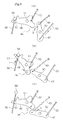
- the positions of the first and second rotating arms 47 and 48 are set in such a way that, when the first rotating arm 47 rotates from its initial position to the terminal position, the first rotating arm 47 presses the second rotating arm 48 to rotate the second rotating arm 48, and then passes the second rotating arm 48 to release the pressing action on the second rotating arm 48 so that the second rotating arm 48 is rotated to its initial position by the action of the fourth spring means 52.
- the first locking member 23 is rotated to the locking position shown in Fig. 5(a) , whereby the engaging concave portion 30 of the first locking member 23 comes into engagement with the first striker 31.
- the first pawl 26 is rotated in the direction opposite to the direction indicated by the arrow I in Fig. 5(a) by the pulling action of the first spring means 28, whereby the first pawl 26 comes into engagement with the engaging portion 29 of the first locking member 23.
- the first pawl 26 is rotated to its engaging position. In this manner, the seat cushion 13 is locked to its use position.
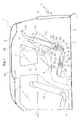
- first and second locking members 23 and 24 provided on one of the end portions of the seat in the vehicle width direction, and the constitution associated with these members.
- the automobile of present embodiment has the first and second locking members on the other end portion of the seat in the vehicle width direction as well, and the components associated with these first and second locking members. These components are not different from the abovementioned first and second locking members 23 and 24 and the constitution associated therewith, hence the explanation thereof is omitted.
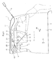
- the automobile of present embodiment has the third locking member 61 that is engaged with the third striker 62 fixed to the vehicle body 1 when the seat back 12 is in its non-use position, in order to lock the seat back 12 to the vehicle body 1.
- the third locking member 61 is supported on the seat back 12 so as to be rotatable between the locking position where the engaging concave portion 69 of the third locking member 61 is engaged with the third striker 62 to lock the seat back 12 to its non-use position, and the lock releasing position where the engaging concave portion 69 is removed from the third striker 62 to release the lock of the seat back 12 to the vehicle body 1.
Landscapes
- Engineering & Computer Science (AREA)
- Aviation & Aerospace Engineering (AREA)
- Transportation (AREA)
- Mechanical Engineering (AREA)
- Seats For Vehicles (AREA)
Applications Claiming Priority (1)
| Application Number | Priority Date | Filing Date | Title |
|---|---|---|---|
| JP2007120021A JP4190566B2 (ja) | 2007-04-27 | 2007-04-27 | 自動車 |
Publications (2)
| Publication Number | Publication Date |
|---|---|
| EP1985492A2 true EP1985492A2 (fr) | 2008-10-29 |
| EP1985492A3 EP1985492A3 (fr) | 2009-06-24 |
Family
ID=39705074
Family Applications (1)
| Application Number | Title | Priority Date | Filing Date |
|---|---|---|---|
| EP08155231A Withdrawn EP1985492A3 (fr) | 2007-04-27 | 2008-04-25 | Automobile |
Country Status (4)
| Country | Link |
|---|---|
| US (1) | US7878569B2 (fr) |
| EP (1) | EP1985492A3 (fr) |
| JP (1) | JP4190566B2 (fr) |
| CN (1) | CN101293490B (fr) |
Cited By (3)
| Publication number | Priority date | Publication date | Assignee | Title |
|---|---|---|---|---|
| EP2749447A1 (fr) | 2012-12-27 | 2014-07-02 | ALSTOM Transport SA | Procédé d'optimisation du fonctionnement d'une sous-station réversible de traction et dispositifs associés |
| GB2510947A (en) * | 2013-12-02 | 2014-08-20 | Daimler Ag | Arrangement of a seat in an interior of a vehicle |
| EP3715172A1 (fr) | 2019-03-25 | 2020-09-30 | ALSTOM Transport Technologies | Procédé d'adaptation dynamique du fonctionnement d'au moins une sous-station de traction d'un système d'alimentation en puissance électrique de véhicules ferroviaires, programme d'ordinateur et dispositif associé |
Families Citing this family (5)
| Publication number | Priority date | Publication date | Assignee | Title |
|---|---|---|---|---|
| CA2626557A1 (fr) * | 2005-11-17 | 2007-05-24 | Intier Automotive Inc. | Siege basculant superpose |
| JP4190567B2 (ja) * | 2007-05-08 | 2008-12-03 | 関東自動車工業株式会社 | 自動車 |
| JP4374383B2 (ja) * | 2007-07-14 | 2009-12-02 | 関東自動車工業株式会社 | 自動車 |
| JP5922482B2 (ja) * | 2012-04-27 | 2016-05-24 | 富士機工株式会社 | シートの固定装置 |
| US11904742B2 (en) * | 2021-04-27 | 2024-02-20 | Ford Global Technologies, Llc | Autonomous vehicle configurable for transportation of passengers and cargo |
Citations (2)
| Publication number | Priority date | Publication date | Assignee | Title |
|---|---|---|---|---|
| EP0987140A2 (fr) | 1998-09-17 | 2000-03-22 | Magna-Sitzsysteme GmbH | Banquette pour véhicules automobiles |
| JP2001130303A (ja) | 1999-11-05 | 2001-05-15 | Daihatsu Motor Co Ltd | 自動車用シートの格納装置 |
Family Cites Families (9)
| Publication number | Priority date | Publication date | Assignee | Title |
|---|---|---|---|---|
| DE2739415C2 (de) * | 1977-09-01 | 1982-07-29 | M.A.N. Maschinenfabrik Augsburg-Nürnberg AG, 8000 München | Schlafeinrichtung in Fernfahrerhäusern für Lastkraftwagen mit Wohnwageneinbauten |
| US6073986A (en) * | 1997-03-14 | 2000-06-13 | Magna Interior Systems, Inc. | Easily handled movable vehicle seat assembly |
| WO1999047378A1 (fr) * | 1998-03-13 | 1999-09-23 | Magna Interior Systems Inc. | Ensemble siege d'automobile retractable |
| US6631946B1 (en) * | 1998-05-29 | 2003-10-14 | Magna Interior Systems, Inc. | Stowable automotive seat assembly |
| US6981731B2 (en) * | 2001-01-12 | 2006-01-03 | Intier Automotive Inc. | Retractable seat assembly for a motor vehicle |
| US6758527B2 (en) * | 2002-05-15 | 2004-07-06 | Daimlerchrysler Corporation | Headrest retractable against motor vehicle headliner |
| JP4066756B2 (ja) | 2002-09-17 | 2008-03-26 | マツダ株式会社 | 車両用のシート格納構造 |
| CA2626557A1 (fr) * | 2005-11-17 | 2007-05-24 | Intier Automotive Inc. | Siege basculant superpose |
| JP4374383B2 (ja) * | 2007-07-14 | 2009-12-02 | 関東自動車工業株式会社 | 自動車 |
-
2007
- 2007-04-27 JP JP2007120021A patent/JP4190566B2/ja not_active Expired - Fee Related
-
2008
- 2008-04-16 US US12/103,913 patent/US7878569B2/en not_active Expired - Fee Related
- 2008-04-25 EP EP08155231A patent/EP1985492A3/fr not_active Withdrawn
- 2008-04-25 CN CN2008100959183A patent/CN101293490B/zh not_active Expired - Fee Related
Patent Citations (2)
| Publication number | Priority date | Publication date | Assignee | Title |
|---|---|---|---|---|
| EP0987140A2 (fr) | 1998-09-17 | 2000-03-22 | Magna-Sitzsysteme GmbH | Banquette pour véhicules automobiles |
| JP2001130303A (ja) | 1999-11-05 | 2001-05-15 | Daihatsu Motor Co Ltd | 自動車用シートの格納装置 |
Cited By (4)
| Publication number | Priority date | Publication date | Assignee | Title |
|---|---|---|---|---|
| EP2749447A1 (fr) | 2012-12-27 | 2014-07-02 | ALSTOM Transport SA | Procédé d'optimisation du fonctionnement d'une sous-station réversible de traction et dispositifs associés |
| GB2510947A (en) * | 2013-12-02 | 2014-08-20 | Daimler Ag | Arrangement of a seat in an interior of a vehicle |
| EP3715172A1 (fr) | 2019-03-25 | 2020-09-30 | ALSTOM Transport Technologies | Procédé d'adaptation dynamique du fonctionnement d'au moins une sous-station de traction d'un système d'alimentation en puissance électrique de véhicules ferroviaires, programme d'ordinateur et dispositif associé |
| FR3094288A1 (fr) | 2019-03-25 | 2020-10-02 | Alstom Transport Technologies | Procédé d’adaptation dynamique du fonctionnement d’au moins une sous-station de traction d’un système d’alimentation en puissance électrique de véhicules ferroviaires, programme d’ordinateur et dispositif associé |
Also Published As
| Publication number | Publication date |
|---|---|
| JP2008273409A (ja) | 2008-11-13 |
| CN101293490A (zh) | 2008-10-29 |
| US7878569B2 (en) | 2011-02-01 |
| US20080265606A1 (en) | 2008-10-30 |
| EP1985492A3 (fr) | 2009-06-24 |
| JP4190566B2 (ja) | 2008-12-03 |
| CN101293490B (zh) | 2012-08-22 |
Similar Documents
| Publication | Publication Date | Title |
|---|---|---|
| US7878569B2 (en) | Automobile | |
| US8424971B2 (en) | Seating system for a vehicle | |
| JP4374383B2 (ja) | 自動車 | |
| EP1990233B1 (fr) | Automobile | |
| US6663181B2 (en) | Vehicle seat portion | |
| JP4790686B2 (ja) | 自動車 | |
| US20030098592A1 (en) | Seat arrangement | |
| JP4353969B2 (ja) | 自動車 | |
| JP3998943B2 (ja) | 車両の乗降補助シート | |
| JP4467073B2 (ja) | ダイブイン格納シート構造 | |
| JP2009023569A (ja) | 自動車 | |
| JP5857919B2 (ja) | ロック機構 | |
| JP6387839B2 (ja) | 乗物用シートのテーブル装置 | |
| JP4968534B2 (ja) | 自動車 | |
| JPH0232511Y2 (fr) | ||
| JP7099301B2 (ja) | 乗物用シート | |
| JP3597497B2 (ja) | 車両用シート | |
| JP4978568B2 (ja) | 自動車 | |
| JP3226366B2 (ja) | 自動車のシート装置 | |
| JP5125612B2 (ja) | 車両用シートの配設構造 | |
| JP2009067152A (ja) | 回動体装置及びその回動体装置を有する自動車 | |
| JP2010100225A (ja) | 自動車用シート | |
| JP2008013151A (ja) | 自動車 |
Legal Events
| Date | Code | Title | Description |
|---|---|---|---|
| PUAI | Public reference made under article 153(3) epc to a published international application that has entered the european phase |
Free format text: ORIGINAL CODE: 0009012 |
|
| AK | Designated contracting states |
Kind code of ref document: A2 Designated state(s): AT BE BG CH CY CZ DE DK EE ES FI FR GB GR HR HU IE IS IT LI LT LU LV MC MT NL NO PL PT RO SE SI SK TR |
|
| AX | Request for extension of the european patent |
Extension state: AL BA MK RS |
|
| PUAL | Search report despatched |
Free format text: ORIGINAL CODE: 0009013 |
|
| AK | Designated contracting states |
Kind code of ref document: A3 Designated state(s): AT BE BG CH CY CZ DE DK EE ES FI FR GB GR HR HU IE IS IT LI LT LU LV MC MT NL NO PL PT RO SE SI SK TR |
|
| AX | Request for extension of the european patent |
Extension state: AL BA MK RS |
|
| 17P | Request for examination filed |
Effective date: 20091221 |
|
| AKX | Designation fees paid |
Designated state(s): DE FR |
|
| 17Q | First examination report despatched |
Effective date: 20120323 |
|
| RAP1 | Party data changed (applicant data changed or rights of an application transferred) |
Owner name: TOYOTA MOTOR EAST JAPAN, INC. Owner name: TOYOTA JIDOSHA KABUSHIKI KAISHA |
|
| RAP1 | Party data changed (applicant data changed or rights of an application transferred) |
Owner name: TOYOTA MOTOR EAST JAPAN, INC. Owner name: TOYOTA JIDOSHA KABUSHIKI KAISHA |
|
| GRAP | Despatch of communication of intention to grant a patent |
Free format text: ORIGINAL CODE: EPIDOSNIGR1 |
|
| INTG | Intention to grant announced |
Effective date: 20130621 |
|
| STAA | Information on the status of an ep patent application or granted ep patent |
Free format text: STATUS: THE APPLICATION IS DEEMED TO BE WITHDRAWN |
|
| 18D | Application deemed to be withdrawn |
Effective date: 20131102 |