EP1984093B1 - Centrifugal separator - Google Patents
Centrifugal separator Download PDFInfo
- Publication number
- EP1984093B1 EP1984093B1 EP07709407.6A EP07709407A EP1984093B1 EP 1984093 B1 EP1984093 B1 EP 1984093B1 EP 07709407 A EP07709407 A EP 07709407A EP 1984093 B1 EP1984093 B1 EP 1984093B1
- Authority
- EP
- European Patent Office
- Prior art keywords
- centrifugal separator
- separator according
- outlet
- extends
- gas
- Prior art date
- Legal status (The legal status is an assumption and is not a legal conclusion. Google has not performed a legal analysis and makes no representation as to the accuracy of the status listed.)
- Active
Links
- 239000007788 liquid Substances 0.000 claims description 74
- 239000012535 impurity Substances 0.000 claims description 35
- 238000000926 separation method Methods 0.000 claims description 27
- 238000011144 upstream manufacturing Methods 0.000 claims description 10
- 238000004140 cleaning Methods 0.000 claims description 5
- 239000007789 gas Substances 0.000 description 42
- 239000002245 particle Substances 0.000 description 6
- 239000003595 mist Substances 0.000 description 4
- 230000002093 peripheral effect Effects 0.000 description 2
- 239000007787 solid Substances 0.000 description 2
- 238000010276 construction Methods 0.000 description 1
- 238000000034 method Methods 0.000 description 1
Images


Classifications
-
- B—PERFORMING OPERATIONS; TRANSPORTING
- B01—PHYSICAL OR CHEMICAL PROCESSES OR APPARATUS IN GENERAL
- B01D—SEPARATION
- B01D45/00—Separating dispersed particles from gases or vapours by gravity, inertia, or centrifugal forces
- B01D45/12—Separating dispersed particles from gases or vapours by gravity, inertia, or centrifugal forces by centrifugal forces
- B01D45/14—Separating dispersed particles from gases or vapours by gravity, inertia, or centrifugal forces by centrifugal forces generated by rotating vanes, discs, drums or brushes
-
- B—PERFORMING OPERATIONS; TRANSPORTING
- B04—CENTRIFUGAL APPARATUS OR MACHINES FOR CARRYING-OUT PHYSICAL OR CHEMICAL PROCESSES
- B04B—CENTRIFUGES
- B04B11/00—Feeding, charging, or discharging bowls
- B04B11/02—Continuous feeding or discharging; Control arrangements therefor
-
- B—PERFORMING OPERATIONS; TRANSPORTING
- B04—CENTRIFUGAL APPARATUS OR MACHINES FOR CARRYING-OUT PHYSICAL OR CHEMICAL PROCESSES
- B04B—CENTRIFUGES
- B04B11/00—Feeding, charging, or discharging bowls
- B04B11/06—Arrangement of distributors or collectors in centrifuges
-
- B—PERFORMING OPERATIONS; TRANSPORTING
- B04—CENTRIFUGAL APPARATUS OR MACHINES FOR CARRYING-OUT PHYSICAL OR CHEMICAL PROCESSES
- B04B—CENTRIFUGES
- B04B5/00—Other centrifuges
- B04B5/08—Centrifuges for separating predominantly gaseous mixtures
-
- B—PERFORMING OPERATIONS; TRANSPORTING
- B04—CENTRIFUGAL APPARATUS OR MACHINES FOR CARRYING-OUT PHYSICAL OR CHEMICAL PROCESSES
- B04B—CENTRIFUGES
- B04B5/00—Other centrifuges
- B04B5/12—Centrifuges in which rotors other than bowls generate centrifugal effects in stationary containers
-
- B—PERFORMING OPERATIONS; TRANSPORTING
- B04—CENTRIFUGAL APPARATUS OR MACHINES FOR CARRYING-OUT PHYSICAL OR CHEMICAL PROCESSES
- B04B—CENTRIFUGES
- B04B7/00—Elements of centrifuges
- B04B7/02—Casings; Lids
-
- F—MECHANICAL ENGINEERING; LIGHTING; HEATING; WEAPONS; BLASTING
- F01—MACHINES OR ENGINES IN GENERAL; ENGINE PLANTS IN GENERAL; STEAM ENGINES
- F01M—LUBRICATING OF MACHINES OR ENGINES IN GENERAL; LUBRICATING INTERNAL COMBUSTION ENGINES; CRANKCASE VENTILATING
- F01M13/00—Crankcase ventilating or breathing
- F01M13/04—Crankcase ventilating or breathing having means for purifying air before leaving crankcase, e.g. removing oil
-
- B—PERFORMING OPERATIONS; TRANSPORTING
- B04—CENTRIFUGAL APPARATUS OR MACHINES FOR CARRYING-OUT PHYSICAL OR CHEMICAL PROCESSES
- B04B—CENTRIFUGES
- B04B5/00—Other centrifuges
- B04B5/12—Centrifuges in which rotors other than bowls generate centrifugal effects in stationary containers
- B04B2005/125—Centrifuges in which rotors other than bowls generate centrifugal effects in stationary containers the rotors comprising separating walls
-
- F—MECHANICAL ENGINEERING; LIGHTING; HEATING; WEAPONS; BLASTING
- F01—MACHINES OR ENGINES IN GENERAL; ENGINE PLANTS IN GENERAL; STEAM ENGINES
- F01M—LUBRICATING OF MACHINES OR ENGINES IN GENERAL; LUBRICATING INTERNAL COMBUSTION ENGINES; CRANKCASE VENTILATING
- F01M13/00—Crankcase ventilating or breathing
- F01M13/04—Crankcase ventilating or breathing having means for purifying air before leaving crankcase, e.g. removing oil
- F01M2013/0422—Separating oil and gas with a centrifuge device
Definitions
- the present invention refers generally to a centrifugal separator for cleaning of gases from liquid impurities, such as oil particles and oil mist. More specifically, the invention refers to a centrifugal separator according to the preamble of claim 1.
- SE-C-523 690 discloses such a centrifugal separator which is intended for cleaning of a gas containing liquid impurities in the form of oil particles and/or oil mist.
- the gas outlet for the cleaned gas extends in the known centrifugal separator from a lower part of the separation space.
- a shield element which extends into the separation space.
- the technique disclosed in SE-C-523 690 is based on the phenomenon that the shield element will create an annular gas cushion immediately above the shield element, and that this gas cushion will stop up the downwardly flowing oil at the level of the upper end of the gas cushion and at the level of the outlet holes so that the oil may be discharged through the outlet holes.
- the outlet holes of the known centrifugal separator are equidistantly located along the periphery of the casing. This means that the oil that is discharged through the holes has to be collected outside the casing for the transport to a common outlet.
- the object of the present invention is to provide a centrifugal separator which in an efficient manner is capable of separating liquid impurities from a gas. Furthermore, it is aimed at a centrifugal separator which has a simple construction and which prevents separated liquid impurities from being remixed with gas before the gas leaves the centrifugal separator.
- centrifugal separator initially defined, which is characterized in that it comprises a surrounding ring groove, which extends outwardly from the inner wall surface in the stationary casing and has a surrounding bottom surface, wherein the outlet hole extends outwardly from the bottom surface.
- the first liquid outlet also comprises an annular collecting channel, which extends around the separation space radially outside the ring groove.
- the separated liquid impurities are collected in an easy and convenient manner and will thereafter be conveyed away from the centrifugal separator by means of one single conduit.
- the outlet hole may extend between the ring groove and the collecting channel so that the liquid impurities flowing in the direction of rotation in the ring groove in an easy manner can be discharged to the annular collecting channel.
- the ring groove has a first limiting wall, which extends downstream the bottom surface between the bottom surface and the inner wall surface, wherein the outlet hole has an upper point which lies substantially at the level of the first limiting wall. Consequently, it is ensured that all liquid impurities flowing in the ring groove will be discharged through the outlet hole to the annular collecting channel.
- the first limiting wall may extend substantially in parallel with a radial plane.
- the ring groove has a second limiting wall, which extends upstream the bottom surface between the bottom surface and the inner wall surface.
- the second limiting wall is inclined in relation to a radial plane.
- the centrifugal separator comprises at least one guide vane, which is provided for guiding the flow of separated liquid impurities through the outlet hole.
- the guide vane may extend through the outlet hole, wherein the liquid impurities in an efficient manner are conveyed in through the outlet hole and into the annular collecting channel.
- the guide vane may advantageously extend in at least one direction which is inclined outwardly and forwardly in relation to a tangent to the direction of rotation at the outlet hole.
- the outlet hole has in relation to the direction of rotation a forward limiting surface and a rearward limiting surface, wherein at least one of these limiting surfaces extends in a direction which is inclined outwardly and forwardly in relation to a tangent to the direction of rotation at the outlet hole.
- the centrifugal separator comprises a second liquid outlet, which is provided upstream the first liquid outlet.
- the second liquid outlet may then form a main outlet and the first liquid outlet a residual outlet.
- the second liquid outlet comprises an annular collecting channel, which extends around the separation space radially outside the inner wall surface. Furthermore, the second liquid outlet may comprise at least one outlet hole which extends between the separation space and the annular collecting channel.
- the centrifugal separator is arranged to be provided in such a way that the axis of rotation extends substantially vertically, wherein the stationary casing has an upper end and a lower end and wherein the gas outlet is provided at the upper end.
- the second liquid outlet may then be provided at the lower end, wherein a main part of the liquid impurities will flow along the inner wall surface down to the second liquid outlet. A probably smaller part of the liquid impurities will due to the upwardly flowing gas flow be transported upwardly along the inner wall surface to the ring groove and the first liquid outlet.
- the separation space comprises a lower annular end surface, which extends between the rotating member and the inner wall surface, wherein the lower end surface is configured to transport liquid impurities radially outwardly to the second liquid outlet.
- the centrifugal separator may comprise a number of guide elements provided on the lower end surface and arranged to promote said transport. Said guide elements, seen radially outwardly, are advantageously directed forwardly in the direction of rotation. By means of such inclined or in relation to a radial direction sloping guide elements, the liquid impurities will, thanks to the influence from the gas flow in the separation space, be conveyed outwardly towards a larger diameter and thus to the inner wall surface and the second liquid outlet.
- Said guide elements may be configured as ribs extending upwardly from the lower end surface or as grooves extending downwardly from the lower end surface.
- the lower end surface is conical and inclined outwardly and downwardly.
- the rotating member comprises a number of separating discs.
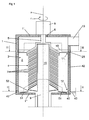
- Fig. 1 discloses a centrifugal separator for cleaning of a gas containing liquid impurities, for instance oil in the form of oil mist or oil particles, and possibly solid particles.
- the centrifugal separator comprises a stationary casing 1, which encloses a substantially closed separation space 2.
- the casing 1 has an inner wall surface 3, which faces the separation space 2.
- the separation space 2 is arranged to permit the gas to flow therethrough.
- the centrifugal separator also comprises a rotating member 4 which is provided in the separation space 2 and arranged to rotate in a direction r of rotation around an axis x of rotation, which also forms a centre axis through the casing 1.
- the centrifugal separator is provided in such a way that the axis x of rotation extends substantially vertically so that the stationary casing 1 has an upper end 1' and a lower end 1".
- the rotating member 4 comprises a spindle member 5, which is journalled in the casing 1 at the upper end 1' by means of a bearing 6, and a number of separating discs 7.
- the separating discs 7 are conical and extend obliquely downwardly and outwardly from the spindle member 5.
- the invention is also applicable to rotating members having completely radial separating discs or separating discs extending in axial planes from the spindle member 5.
- the rotating member 4 is driven by means of a drive member 8, for instance an electrical motor, and is adapted to bring the gas to rotation in the direction r of rotation for separating, by means of centrifugal forces, the liquid impurities from the gas.
- the centrifugal separator also comprises an inlet 9 for the gas to be cleaned, a gas outlet 10 for the cleaned gas, a first liquid outlet 11 for the separated liquid impurities and a second liquid outlet 12 for the separated liquid impurities.
- the inlet 9 is centrally provided and extends through the lower end 1" of the casing 1.
- the inlet 9 conveys the gas into a central space 15 of the rotating member 4. From this central space 15, the gas is conveyed radially outwardly to the gaps formed between the separating discs 7.
- the gas outlet 10 is provided at the upper end 1' of the casing 1 downstream the rotating member 4. The gas leaving the gaps between the separating discs 7 thus rotates at a high rotary speed in the direction r of rotation and will continue this rotating movement upwardly to the gas outlet 10 where the cleaned gas leaves the separation space 2.
- the first liquid outlet 11 is provided upstream the gas outlet 10 and downstream the rotating member 4 with respect to the gas flow.
- the second liquid outlet 12 is provided at the lower end 1" of the casing 1 and upstream the first liquid outlet 11 with respect to the gas flow.
- the second liquid outlet 12 forms a main outlet, which is adapted for discharge of a main part of the liquid impurities, and the first liquid outlet 11 a residual outlet, which is adapted for discharge of substantially all residual liquid impurities.
- the separated liquid impurities may contain solid particles which are discharged via the liquid outlets 11 and 12.
- the centrifugal separator comprises a surrounding ring groove 19, which extends outwardly from the inner wall surface 3 and into the wall of the stationary casing 1.
- the ring groove 19, see Fig 6 has a surrounding bottom surface 20.
- the bottom surface 20 extends substantially in parallel with the axis x of rotation.
- the ring groove 19 also has a first, upper limiting wall 21, which extends downstream the bottom surface 20 between the bottom surface 20 and the inner wall surface 3.
- the first limiting wall 21 extends substantially in parallel with a plane being radial in relation to the axis x of rotation.
- the ring groove 19 also has a second, lower limiting wall 22, which extends upstream the bottom surface 20 between the bottom surface 20 and the inner wall surface 3.
- the second limiting wall 22 is inclined in relation to a radial plane, and more precisely radially outwardly and upwardly from the inner wall surface 3.
- the ring groove 19 is in the embodiment disclosed provided immediately below the gas outlet 10 at the level of an upper part of the rotating member 4. More precisely, the ring groove 19 is located at the level of the uppermost separating disc 7 and somewhat above the outlet of the gap formed between the two uppermost separating discs 7.
- the centrifugal separator comprises an annular collecting channel 25, which extends around the separation space 2 radially outside the ring groove 19 in a peripheral direction.
- the collecting channel 25 extends in the wall of the stationary casing 1 at the level of the ring groove 19.
- the first liquid outlet 11 comprises at least one outlet hole 26, which extends outwardly from the bottom surface 20 and forms a passage between the ring groove 19 and the collecting channel 25.
- three such outlet holes 26 are provided between the ring groove 19 and the collecting channel 25.
- the centrifugal separator may comprise another number than the disclosed three outlet holes 26, for instance 1, 2, 4, 5, 6 or more outlet holes 26.
- each such outlet hole 26 has in the embodiment disclosed an upper point located below the first limiting wall 21, see Fig 4 .
- Each outlet hole 26 has, in relation to the direction r of rotation, a forward limiting surface 27 and a rearward limiting surface 28, see Fig 5 . At least one of these limiting surfaces 27, 28 extends in a direction, which is inclined outwardly and forwardly in relation to a tangent of the direction r of rotation at the outlet hole 26 concerned. In the embodiment disclosed, both the forward limiting surface 27 and the rearward limiting surface 28 are inclined in such a direction.
- Each outlet hole 26 also comprises a guide vane 29, which is provided to guide the flow of the separated liquid impurities through the outlet hole 26.
- a guide vane 29, which is disclosed more closely in Fig 4 , extends through the outlet hole 26 and more precisely from an inner end at the level of the inner wall surface 3 to an outer end located in the collecting channel 25.
- Each guide vane 29 extends at least in one direction, which is inclined outwardly and forwardly in relation to a tangent of the direction r of rotation at the outlet hole 26.
- each guide vane 29 has in the embodiment disclosed a first inner part 29', which has a more radial inclination outwardly than a second outer part 29" of the guide vane 29.
- the centrifugal separator also may comprise guide vanes having another configuration and another location for guiding the flow of liquid impurities towards and through the outlet holes 26.
- the centrifugal separator may comprise one or several guide vanes 30, which are located upstream the outlet hole 26 seen in the direction r of rotation.
- the guide vanes 30 are provided on the second inclined limiting wall 22 and are inclined obliquely upwardly in the direction r of rotation.
- the guide member 31 extends along the height of the whole bottom surface 20 and is inclined forwardly and downwardly in the direction of rotation.
- the guide member 31 may be configured as a groove, or as a projecting guide element.
- the guide member 31 may also be configured in such a way that it merely comprises one limiting surface, which extends inwardly from the bottom wall 20 whereafter the bottom wall 20 very slowly again reaches its peripheral level.
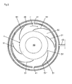
- the second liquid outlet 12 also comprises an annular collecting channel 40, which extends around the separation space 2 radially outside the inner wall surface 3. Furthermore, at least one outlet hole 41 is provided so that it extends between the separation space 3 and the collecting channel 40. In the embodiment disclosed, there are two such outlet holes 41, see Fig 2 . It is to be noted that the centrifugal separator may comprise another number than the disclosed two outlet holes 41, for instance 1, 3, 4, 5, 6 or more outlet holes 41.
- the second liquid outlet 12, i.e. the outlet holes 41 are provided at the lower end 1 ".
- the annular collecting channel 25 of the first liquid outlet 11 is connected to the annular collecting channel 40 of the second liquid outlet 12 via at least one connecting channel 42, which in the embodiment disclosed extends substantially in parallel with the axis x of rotation. It is of course possible to provide more than one such connecting channel 42. From the annular collecting channel 40 also at least one discharge conduit 43 extends for discharge of the separated liquid impurities from the centrifugal separator.
- the centrifugal separator also comprises a lower annular end surface 50, which extends between the rotating member 4 and the inner wall surface 3.
- the lower end surface 50 is configured to transport liquid impurities radially outwardly to the second liquid outlet 12.
- the lower end surface 50 is in the embodiment disclosed slightly conical and inclined outwardly and downwardly, see Fig 1 . It is to be noted, however, that the lower end surface 50 also may be substantially plannar or even inclined somewhat outwardly and upwardly.
- the centrifugal separator comprises a number of guide elements 51, which are provided on the lower end surface 50 and arranged to promote the transport of the liquid impurities outwardly towards the inner wall surface 3 and the outlet holes 41.
- the guide elements 51 are, seen radially outwardly, directed forwardly in the direction r of rotation.
- the guide elements 51 may be straight or, as in the embodiment disclosed, curved.
- the centrifugal separator has six guide elements 51. However, it is to be noted that more or less such guide elements 51 may be provided on the lower end surface 50.
- the outlet holes 41 adjoin the lower end surface 50, i.e. the outlet holes 41 have a lower end located at the level of the lower end surface at its radially outer periphery ;
- the guide elements 51 are configured as ribs, which extend upwardly from the lower end surface 50, see Fig 7 .
- the guide elements 51 may then have a height from the lower end surface 50 that it as least approximately 1 mm.
- the guide elements 51 may also be configured as grooves extending downwardly from the lower end surface 50, see Fig 8 .
- the guide elements 51 may have a height or a depth of at least approximately 1 mm from the lower end surface 50.
- Each guide element 51 has a first radially inner end 51' and a second radially outer end 51".
- the radially outer end 51" is located in the proximity of but at a distance from the inner wall surface 3 so that a radially outer passage is formed between the inner wall surface 3 and the radially outer end 51', see Fig 2 .
- the radially inner end 51' is located in the proximity of but at a distance from an annular inner end of the annular surface 50 so that a radially inner passage is formed between the annular inner end and the radially inner end 51' of each guide element, see Fig 2 .
- the centrifugal separator disclosed may for instance be used for cleaning of gas containing oil in the form of oil particles and/or oil mist.
- the gas to be cleaned may then be conveyed via the inlet 9 to the space 15. Due to the rotation of the rotating member 4, the gas will also be sucked into the gaps between the separating discs 7, wherein oil will be attached to these discs 7 and due to the centrifugal force transported outwardly on the discs 7.
- the oil then leaves the discs 7 and is thrown against the inner wall surface 3.
- the oil will then flow downwardly on the inner wall surface 3 to the lower end surface 50 and the second liquid outlet 12 where the oil will flow out through the outlet holes 41 into the collecting channel 40.
- a part of the oil, which hits the inner wall surface 3, will, due to the upward gas flow from the rotating member to the gas outlet 10, be transported upwardly along the inner wall surface 3. This oil will flow down into the ring groove 19 and be conveyed into the collecting channel 25 via the outlet holes 26. From the collecting channel 25, the separated oil is then transported down to the collecting channel 40. All separated oil is thus transported to this collecting channel 40, and from there out from the centrifugal separator via the discharge conduit 43.
Landscapes
- Chemical & Material Sciences (AREA)
- Chemical Kinetics & Catalysis (AREA)
- Engineering & Computer Science (AREA)
- Mechanical Engineering (AREA)
- General Engineering & Computer Science (AREA)
- Centrifugal Separators (AREA)
- Cyclones (AREA)
Applications Claiming Priority (2)
| Application Number | Priority Date | Filing Date | Title |
|---|---|---|---|
| SE0600312A SE529610C2 (sv) | 2006-02-13 | 2006-02-13 | Centrifugalseparator |
| PCT/SE2007/050013 WO2007094725A1 (en) | 2006-02-13 | 2007-01-12 | Centrifugal separator |
Publications (3)
| Publication Number | Publication Date |
|---|---|
| EP1984093A1 EP1984093A1 (en) | 2008-10-29 |
| EP1984093A4 EP1984093A4 (en) | 2012-01-11 |
| EP1984093B1 true EP1984093B1 (en) | 2014-08-20 |
Family
ID=38371813
Family Applications (1)
| Application Number | Title | Priority Date | Filing Date |
|---|---|---|---|
| EP07709407.6A Active EP1984093B1 (en) | 2006-02-13 | 2007-01-12 | Centrifugal separator |
Country Status (8)
| Country | Link |
|---|---|
| US (1) | US7824459B2 (ru) |
| EP (1) | EP1984093B1 (ru) |
| JP (1) | JP5009315B2 (ru) |
| KR (1) | KR101183803B1 (ru) |
| CN (1) | CN101384329B (ru) |
| RU (1) | RU2423169C2 (ru) |
| SE (1) | SE529610C2 (ru) |
| WO (1) | WO2007094725A1 (ru) |
Families Citing this family (70)
| Publication number | Priority date | Publication date | Assignee | Title |
|---|---|---|---|---|
| US8075668B2 (en) | 2005-03-29 | 2011-12-13 | Dresser-Rand Company | Drainage system for compressor separators |
| SE529611C2 (sv) * | 2006-02-13 | 2007-10-02 | Alfa Laval Corp Ab | Centrifugalseparator |
| CA2664121C (en) | 2006-09-19 | 2014-05-27 | William C. Maier | Rotary separator drum seal |
| US8302779B2 (en) | 2006-09-21 | 2012-11-06 | Dresser-Rand Company | Separator drum and compressor impeller assembly |
| BRPI0717088B1 (pt) | 2006-09-25 | 2019-10-29 | Dresser Rand Co | sistema de proteção de acoplamento |
| MX2009003178A (es) | 2006-09-25 | 2009-04-03 | Dresser Rand Co | Sistema de montaje de compresor. |
| WO2008039731A2 (en) | 2006-09-25 | 2008-04-03 | Dresser-Rand Company | Access cover for pressurized connector spool |
| EP2066949B1 (en) | 2006-09-25 | 2013-08-28 | Dresser-Rand Company | Axially moveable spool connector |
| BRPI0718451A2 (pt) | 2006-09-25 | 2013-11-26 | Dresser Rand Co | Defletor de fluido para dispositivos separadores de fluido |
| EP2415507A1 (en) | 2006-09-26 | 2012-02-08 | Dresser-Rand Company | Improved static fluid separator device |
| WO2009051545A1 (en) * | 2007-10-15 | 2009-04-23 | Atlas Copco Drills Ab | Device and method for separating particles out from a fluid |
| GB2470151B (en) | 2008-03-05 | 2012-10-03 | Dresser Rand Co | Compressor assembly including separator and ejector pump |
| US20090242481A1 (en) * | 2008-03-31 | 2009-10-01 | Ewout Carel Barents | Gas/liquid separator with non-square-edged outlet openings |
| US8062400B2 (en) | 2008-06-25 | 2011-11-22 | Dresser-Rand Company | Dual body drum for rotary separators |
| US7922218B2 (en) | 2008-06-25 | 2011-04-12 | Dresser-Rand Company | Shear ring casing coupler device |
| US8079805B2 (en) | 2008-06-25 | 2011-12-20 | Dresser-Rand Company | Rotary separator and shaft coupler for compressors |
| FI20086233A0 (fi) * | 2008-12-22 | 2008-12-22 | Waertsilae Finland Oy | Menetelmä ja laite partikkeleiden poistamiseksi pakokaasuista |
| US8087901B2 (en) | 2009-03-20 | 2012-01-03 | Dresser-Rand Company | Fluid channeling device for back-to-back compressors |
| US8210804B2 (en) | 2009-03-20 | 2012-07-03 | Dresser-Rand Company | Slidable cover for casing access port |
| US8061972B2 (en) | 2009-03-24 | 2011-11-22 | Dresser-Rand Company | High pressure casing access cover |
| CN103357515B (zh) * | 2009-07-10 | 2015-11-18 | 阿尔法拉瓦尔股份有限公司 | 气体净化分离器 |
| EP2478229B1 (en) | 2009-09-15 | 2020-02-26 | Dresser-Rand Company | Improved density-based compact separator |
| CN101716431B (zh) * | 2009-11-06 | 2014-07-09 | 重庆工商大学 | 自吸式离心分离的乳化油破乳处理机 |
| US8940068B2 (en) | 2010-01-27 | 2015-01-27 | Cummins Filtration Ip Inc. | Magnetically driven rotating separator |
| US8794222B2 (en) * | 2010-01-27 | 2014-08-05 | Cummins Filtration Ip, Inc. | Crankcase ventilation inside-out flow rotating coalescer |
| US8974567B2 (en) | 2010-01-27 | 2015-03-10 | Cummins Filtration Ip Inc. | Rotating coalescer with keyed drive |
| US9194265B2 (en) * | 2010-01-27 | 2015-11-24 | Cummins Filtration Ip, Inc. | Rotating separator with housing preventing separated liquid carryover |
| US8893689B2 (en) | 2010-01-27 | 2014-11-25 | Cummins Filtration Ip, Inc. | Crankcase ventilation self-cleaning coalescer with intermittent rotation |
| EP2533905B1 (en) | 2010-02-10 | 2018-07-04 | Dresser-Rand Company | Separator fluid collector and method |
| SE534773C2 (sv) | 2010-04-09 | 2011-12-13 | Alfa Laval Corp Ab | Centrifugalseparator anordnad inuti en förbränningsmotor |
| US8663483B2 (en) | 2010-07-15 | 2014-03-04 | Dresser-Rand Company | Radial vane pack for rotary separators |
| US8673159B2 (en) | 2010-07-15 | 2014-03-18 | Dresser-Rand Company | Enhanced in-line rotary separator |
| WO2012012018A2 (en) | 2010-07-20 | 2012-01-26 | Dresser-Rand Company | Combination of expansion and cooling to enhance separation |
| US8821362B2 (en) | 2010-07-21 | 2014-09-02 | Dresser-Rand Company | Multiple modular in-line rotary separator bundle |
| US8596292B2 (en) | 2010-09-09 | 2013-12-03 | Dresser-Rand Company | Flush-enabled controlled flow drain |
| WO2012077843A1 (ko) * | 2010-12-09 | 2012-06-14 | 한국과학기술원 | 플라즈마 발생 장치 |
| US9024493B2 (en) | 2010-12-30 | 2015-05-05 | Dresser-Rand Company | Method for on-line detection of resistance-to-ground faults in active magnetic bearing systems |
| US8994237B2 (en) | 2010-12-30 | 2015-03-31 | Dresser-Rand Company | Method for on-line detection of liquid and potential for the occurrence of resistance to ground faults in active magnetic bearing systems |
| US9551349B2 (en) | 2011-04-08 | 2017-01-24 | Dresser-Rand Company | Circulating dielectric oil cooling system for canned bearings and canned electronics |
| DE102011076465B4 (de) * | 2011-05-25 | 2021-04-29 | Hengst Se | Zentrifugalabscheider zum Abscheiden von Ölnebel aus dem Kurbelgehäuseentlüftungsgas einer Brennkraftmaschine |
| EP2715167B1 (en) | 2011-05-27 | 2017-08-30 | Dresser-Rand Company | Segmented coast-down bearing for magnetic bearing systems |
| US8851756B2 (en) | 2011-06-29 | 2014-10-07 | Dresser-Rand Company | Whirl inhibiting coast-down bearing for magnetic bearing systems |
| EP2574389B1 (en) * | 2011-09-29 | 2022-09-28 | Alfa Laval Corporate AB | A device comprising a centrifugal separator and a method for cleaning of a gas |
| BR112014009743A2 (pt) * | 2011-11-04 | 2017-05-02 | Cummins Filtration Ip Inc | separador giratório para separar líquido de mistura fluida |
| JP5667651B2 (ja) * | 2013-02-28 | 2015-02-12 | 川崎重工業株式会社 | ミストセパレータ |
| CN104226023B (zh) * | 2014-04-29 | 2017-01-11 | 俞春华 | 一种离心沉流式气液分离装置 |
| EP2939747B1 (en) * | 2014-04-30 | 2016-08-03 | Alfa Laval Corporate AB | A centrifugal separator |
| EP2939746B1 (en) | 2014-04-30 | 2016-09-07 | Alfa Laval Corporate AB | A centrifugal separator |
| CN104437895B (zh) * | 2014-10-28 | 2016-08-24 | 无锡伊佩克科技有限公司 | 一种泥沙和水的分离处理设备 |
| DE112015006228T5 (de) | 2015-03-30 | 2017-11-09 | Cummins Filtration Ip, Inc. | Mehrstufige rotierende Tropfenabscheidervorrichtungen |
| CN107614841B (zh) | 2015-06-09 | 2020-02-21 | 康明斯过滤Ip公司 | 使用低摩擦旋转聚结器接触密封的系统和方法 |
| US11918948B2 (en) | 2015-06-09 | 2024-03-05 | Cummins Filtration Ip, Inc. | Systems and methods for rotating coalescers maintaining positive recirculation through a dynamic seal |
| CN107847839B (zh) | 2015-08-21 | 2020-05-29 | 康明斯过滤Ip公司 | 高速旋转曲轴箱通风过滤介质和介质包 |
| WO2017040256A1 (en) | 2015-08-28 | 2017-03-09 | Cummins Filtration Ip, Inc | Rotating coalescing element with directed liquid drainage and gas outlet |
| WO2017053267A1 (en) | 2015-09-24 | 2017-03-30 | Cummins Filtration Ip, Inc. | Utilizing a mechanical seal between a filter media and an end cap of a rotating filter cartridge |
| EP3156114B1 (en) * | 2015-10-14 | 2018-04-04 | Alfdex AB | A separator arrangement for cleaning gas |
| CN105735944B (zh) * | 2016-03-07 | 2018-02-16 | 西南石油大学 | 一种油气放喷处理装置及方法 |
| EP3449106B1 (en) | 2016-04-28 | 2021-04-07 | Cummins Filtration IP, Inc. | Inside-out rotating coalescer with gas exit through hollow shaft |
| CN105840270B (zh) * | 2016-05-04 | 2018-05-29 | 合肥恒信汽车发动机部件制造有限公司 | 一种主动式多级油气分离器 |
| EP3287193B1 (en) | 2016-08-25 | 2021-05-26 | Alfdex AB | Control of a centrifugal separator |
| EP3287194B1 (en) | 2016-08-25 | 2021-01-13 | Alfdex AB | High speed cleaning of a centrifugal separator |
| DE112018002354T5 (de) | 2017-06-20 | 2020-01-23 | Cummins Filtration Ip, Inc. | Axialstromzentrifugalabscheider |
| CN107837610B (zh) * | 2017-12-22 | 2023-08-08 | 佛山市普蓝环境工程有限公司 | 一种高效气液分离器 |
| KR102219775B1 (ko) * | 2019-06-03 | 2021-02-25 | 한국기계연구원 | 세정 기능을 구비한 원심분리형 집진장치 |
| CN110173325B (zh) * | 2019-06-28 | 2020-07-24 | 浙江吉利控股集团有限公司 | 一种主动式油气分离器 |
| CN111632435B (zh) * | 2020-06-13 | 2022-06-14 | 山西省太原固体废物处置中心(有限公司) | 一种含液危化品废气净化方法 |
| CN113006926B (zh) * | 2021-04-20 | 2022-12-02 | 一汽解放汽车有限公司 | 一种膨胀水箱、发动机冷却系统及车辆 |
| CN113108384A (zh) * | 2021-05-12 | 2021-07-13 | 河南黎明重工科技股份有限公司 | 离心式除湿机及除湿方法 |
| CN113577966B (zh) * | 2021-08-19 | 2022-09-13 | 界首市振航塑料机械有限公司 | 一种可视化塑料造粒烟气智能处理装置 |
| CN114777346B (zh) * | 2022-06-20 | 2022-09-02 | 浙江大学 | 油与液态制冷剂及固相杂质旋流分离制冷循环系统 |
Family Cites Families (27)
| Publication number | Priority date | Publication date | Assignee | Title |
|---|---|---|---|---|
| US2104683A (en) * | 1933-07-06 | 1938-01-04 | Rosen Van | Dust separator |
| US2335420A (en) * | 1941-04-26 | 1943-11-30 | Sharples Corp | Oil purifying system for vehicles |
| US3005515A (en) * | 1959-05-12 | 1961-10-24 | Alfred M Caddell | Centrifugal fluid cleaner |
| NL285656A (ru) * | 1961-11-22 | |||
| US3447290A (en) * | 1967-09-18 | 1969-06-03 | Frick Co | Separator for disentrainment of material from a gaseous fluid stream |
| US4198218A (en) * | 1979-03-23 | 1980-04-15 | Kobe, Inc. | Gas separation apparatus |
| JPS5648209A (en) * | 1979-09-28 | 1981-05-01 | Hitachi Ltd | Centrifugal anti-foaming apparatus |
| JPS62183561U (ru) * | 1986-05-15 | 1987-11-21 | ||
| DD287147A7 (de) * | 1988-11-28 | 1991-02-21 | Maschinenfabrik Kyffhaeuserhuette Artern Gmbh,De | Trommel fuer einen zentrifugalseparator |
| JPH02273564A (ja) * | 1989-04-14 | 1990-11-08 | Hitachi Ltd | 気水分離器 |
| JPH0611373B2 (ja) * | 1989-11-16 | 1994-02-16 | 鹿島建設株式会社 | スタックレイン除去装置 |
| CN1082947A (zh) * | 1992-08-26 | 1994-03-02 | 董达 | 离心分离器 |
| US5693125A (en) * | 1995-12-22 | 1997-12-02 | United Technologies Corporation | Liquid-gas separator |
| CN2355771Y (zh) * | 1998-12-18 | 1999-12-29 | 周明连 | 离心净化器 |
| SE515302C2 (sv) * | 1999-11-15 | 2001-07-09 | Alfa Laval Ab | Ett sätt och en apparat för rening av gas |
| SE0003915D0 (sv) * | 2000-10-27 | 2000-10-27 | Alfa Laval Ab | Centrifugalseparator med rotor och drivanordning för denna |
| SE517760C2 (sv) * | 2000-11-14 | 2002-07-09 | Alfa Laval Ab | Centrifugalseparator och centrifugrotor |
| US6547862B2 (en) * | 2001-07-02 | 2003-04-15 | Hamilton Sundstrand | Rotary phase separator with integral accumulator and outlet valve |
| SE520952C2 (sv) * | 2002-01-25 | 2003-09-16 | Alfa Laval Corp Ab | En apparat för samtidig rening av en vätska och en gas |
| SE522473C2 (sv) * | 2002-06-20 | 2004-02-10 | Alfa Laval Corp Ab | Ett sätt och en anordning för rening av vevhusgas |
| SE0201982D0 (sv) * | 2002-06-24 | 2002-06-24 | Alfa Laval Corp Ab | Sätt att rena vevhusgas samt en gasreningsseparator |
| SE523676C2 (sv) * | 2002-09-04 | 2004-05-11 | Alfa Laval Corp Ab | Apparat för rening av gas |
| SE523690C2 (sv) * | 2002-09-10 | 2004-05-11 | 3Nine Ab | Anordning vid en centrifugalseparator |
| WO2004024927A1 (en) | 2002-09-12 | 2004-03-25 | Greenovation Biotech Gmbh | Protein production method |
| US7235177B2 (en) * | 2003-04-23 | 2007-06-26 | Fleetguard, Inc. | Integral air/oil coalescer for a centrifuge |
| SE527719C2 (sv) * | 2004-06-16 | 2006-05-23 | 3Nine Ab | Rotorenhet till en centrifugalseparator |
| SE529611C2 (sv) * | 2006-02-13 | 2007-10-02 | Alfa Laval Corp Ab | Centrifugalseparator |
-
2006
- 2006-02-13 SE SE0600312A patent/SE529610C2/sv not_active IP Right Cessation
-
2007
- 2007-01-12 WO PCT/SE2007/050013 patent/WO2007094725A1/en active Application Filing
- 2007-01-12 KR KR1020087019759A patent/KR101183803B1/ko active IP Right Grant
- 2007-01-12 JP JP2008555194A patent/JP5009315B2/ja not_active Expired - Fee Related
- 2007-01-12 US US12/279,103 patent/US7824459B2/en active Active
- 2007-01-12 EP EP07709407.6A patent/EP1984093B1/en active Active
- 2007-01-12 CN CN2007800052540A patent/CN101384329B/zh active Active
- 2007-01-12 RU RU2008136840/05A patent/RU2423169C2/ru active
Also Published As
| Publication number | Publication date |
|---|---|
| EP1984093A4 (en) | 2012-01-11 |
| WO2007094725A1 (en) | 2007-08-23 |
| CN101384329B (zh) | 2010-12-29 |
| US7824459B2 (en) | 2010-11-02 |
| RU2423169C2 (ru) | 2011-07-10 |
| SE529610C2 (sv) | 2007-10-02 |
| US20090025563A1 (en) | 2009-01-29 |
| CN101384329A (zh) | 2009-03-11 |
| JP2009526645A (ja) | 2009-07-23 |
| RU2008136840A (ru) | 2010-03-20 |
| JP5009315B2 (ja) | 2012-08-22 |
| EP1984093A1 (en) | 2008-10-29 |
| KR20080106901A (ko) | 2008-12-09 |
| KR101183803B1 (ko) | 2012-09-17 |
| SE0600312L (sv) | 2007-08-14 |
Similar Documents
| Publication | Publication Date | Title |
|---|---|---|
| EP1984093B1 (en) | Centrifugal separator | |
| EP1993702B1 (en) | Centrifugal separator | |
| EP1991337B1 (en) | Centrifugal separator | |
| EP3050631B1 (en) | Rotating secondary divider | |
| WO2007094727A1 (en) | Centrifugal separator |
Legal Events
| Date | Code | Title | Description |
|---|---|---|---|
| PUAI | Public reference made under article 153(3) epc to a published international application that has entered the european phase |
Free format text: ORIGINAL CODE: 0009012 |
|
| 17P | Request for examination filed |
Effective date: 20080717 |
|
| AK | Designated contracting states |
Kind code of ref document: A1 Designated state(s): AT BE BG CH CY CZ DE DK EE ES FI FR GB GR HU IE IS IT LI LT LU LV MC NL PL PT RO SE SI SK TR |
|
| A4 | Supplementary search report drawn up and despatched |
Effective date: 20111209 |
|
| RIC1 | Information provided on ipc code assigned before grant |
Ipc: B01D 45/14 20060101AFI20111205BHEP Ipc: B04B 7/02 20060101ALI20111205BHEP Ipc: B04B 11/02 20060101ALI20111205BHEP Ipc: B04B 11/06 20060101ALI20111205BHEP Ipc: F01M 13/04 20060101ALI20111205BHEP Ipc: B04B 5/12 20060101ALI20111205BHEP Ipc: B04B 5/08 20060101ALI20111205BHEP |
|
| DAX | Request for extension of the european patent (deleted) | ||
| GRAP | Despatch of communication of intention to grant a patent |
Free format text: ORIGINAL CODE: EPIDOSNIGR1 |
|
| INTG | Intention to grant announced |
Effective date: 20140324 |
|
| GRAS | Grant fee paid |
Free format text: ORIGINAL CODE: EPIDOSNIGR3 |
|
| GRAA | (expected) grant |
Free format text: ORIGINAL CODE: 0009210 |
|
| AK | Designated contracting states |
Kind code of ref document: B1 Designated state(s): AT BE BG CH CY CZ DE DK EE ES FI FR GB GR HU IE IS IT LI LT LU LV MC NL PL PT RO SE SI SK TR |
|
| REG | Reference to a national code |
Ref country code: GB Ref legal event code: FG4D |
|
| REG | Reference to a national code |
Ref country code: CH Ref legal event code: EP |
|
| REG | Reference to a national code |
Ref country code: AT Ref legal event code: REF Ref document number: 683123 Country of ref document: AT Kind code of ref document: T Effective date: 20140915 |
|
| REG | Reference to a national code |
Ref country code: IE Ref legal event code: FG4D |
|
| REG | Reference to a national code |
Ref country code: DE Ref legal event code: R096 Ref document number: 602007038197 Country of ref document: DE Effective date: 20140925 |
|
| REG | Reference to a national code |
Ref country code: SE Ref legal event code: TRGR |
|
| REG | Reference to a national code |
Ref country code: AT Ref legal event code: MK05 Ref document number: 683123 Country of ref document: AT Kind code of ref document: T Effective date: 20140820 |
|
| REG | Reference to a national code |
Ref country code: NL Ref legal event code: VDEP Effective date: 20140820 |
|
| REG | Reference to a national code |
Ref country code: LT Ref legal event code: MG4D |
|
| PG25 | Lapsed in a contracting state [announced via postgrant information from national office to epo] |
Ref country code: BG Free format text: LAPSE BECAUSE OF FAILURE TO SUBMIT A TRANSLATION OF THE DESCRIPTION OR TO PAY THE FEE WITHIN THE PRESCRIBED TIME-LIMIT Effective date: 20141120 Ref country code: LT Free format text: LAPSE BECAUSE OF FAILURE TO SUBMIT A TRANSLATION OF THE DESCRIPTION OR TO PAY THE FEE WITHIN THE PRESCRIBED TIME-LIMIT Effective date: 20140820 Ref country code: ES Free format text: LAPSE BECAUSE OF FAILURE TO SUBMIT A TRANSLATION OF THE DESCRIPTION OR TO PAY THE FEE WITHIN THE PRESCRIBED TIME-LIMIT Effective date: 20140820 Ref country code: GR Free format text: LAPSE BECAUSE OF FAILURE TO SUBMIT A TRANSLATION OF THE DESCRIPTION OR TO PAY THE FEE WITHIN THE PRESCRIBED TIME-LIMIT Effective date: 20141121 Ref country code: PT Free format text: LAPSE BECAUSE OF FAILURE TO SUBMIT A TRANSLATION OF THE DESCRIPTION OR TO PAY THE FEE WITHIN THE PRESCRIBED TIME-LIMIT Effective date: 20141222 |
|
| PG25 | Lapsed in a contracting state [announced via postgrant information from national office to epo] |
Ref country code: AT Free format text: LAPSE BECAUSE OF FAILURE TO SUBMIT A TRANSLATION OF THE DESCRIPTION OR TO PAY THE FEE WITHIN THE PRESCRIBED TIME-LIMIT Effective date: 20140820 Ref country code: IS Free format text: LAPSE BECAUSE OF FAILURE TO SUBMIT A TRANSLATION OF THE DESCRIPTION OR TO PAY THE FEE WITHIN THE PRESCRIBED TIME-LIMIT Effective date: 20141220 Ref country code: LV Free format text: LAPSE BECAUSE OF FAILURE TO SUBMIT A TRANSLATION OF THE DESCRIPTION OR TO PAY THE FEE WITHIN THE PRESCRIBED TIME-LIMIT Effective date: 20140820 |
|
| PG25 | Lapsed in a contracting state [announced via postgrant information from national office to epo] |
Ref country code: NL Free format text: LAPSE BECAUSE OF FAILURE TO SUBMIT A TRANSLATION OF THE DESCRIPTION OR TO PAY THE FEE WITHIN THE PRESCRIBED TIME-LIMIT Effective date: 20140820 |
|
| PG25 | Lapsed in a contracting state [announced via postgrant information from national office to epo] |
Ref country code: CZ Free format text: LAPSE BECAUSE OF FAILURE TO SUBMIT A TRANSLATION OF THE DESCRIPTION OR TO PAY THE FEE WITHIN THE PRESCRIBED TIME-LIMIT Effective date: 20140820 Ref country code: DK Free format text: LAPSE BECAUSE OF FAILURE TO SUBMIT A TRANSLATION OF THE DESCRIPTION OR TO PAY THE FEE WITHIN THE PRESCRIBED TIME-LIMIT Effective date: 20140820 Ref country code: SK Free format text: LAPSE BECAUSE OF FAILURE TO SUBMIT A TRANSLATION OF THE DESCRIPTION OR TO PAY THE FEE WITHIN THE PRESCRIBED TIME-LIMIT Effective date: 20140820 Ref country code: IT Free format text: LAPSE BECAUSE OF FAILURE TO SUBMIT A TRANSLATION OF THE DESCRIPTION OR TO PAY THE FEE WITHIN THE PRESCRIBED TIME-LIMIT Effective date: 20140820 Ref country code: RO Free format text: LAPSE BECAUSE OF FAILURE TO SUBMIT A TRANSLATION OF THE DESCRIPTION OR TO PAY THE FEE WITHIN THE PRESCRIBED TIME-LIMIT Effective date: 20140820 Ref country code: EE Free format text: LAPSE BECAUSE OF FAILURE TO SUBMIT A TRANSLATION OF THE DESCRIPTION OR TO PAY THE FEE WITHIN THE PRESCRIBED TIME-LIMIT Effective date: 20140820 |
|
| REG | Reference to a national code |
Ref country code: DE Ref legal event code: R097 Ref document number: 602007038197 Country of ref document: DE |
|
| PG25 | Lapsed in a contracting state [announced via postgrant information from national office to epo] |
Ref country code: PL Free format text: LAPSE BECAUSE OF FAILURE TO SUBMIT A TRANSLATION OF THE DESCRIPTION OR TO PAY THE FEE WITHIN THE PRESCRIBED TIME-LIMIT Effective date: 20140820 |
|
| PLBE | No opposition filed within time limit |
Free format text: ORIGINAL CODE: 0009261 |
|
| STAA | Information on the status of an ep patent application or granted ep patent |
Free format text: STATUS: NO OPPOSITION FILED WITHIN TIME LIMIT |
|
| PG25 | Lapsed in a contracting state [announced via postgrant information from national office to epo] |
Ref country code: BE Free format text: LAPSE BECAUSE OF NON-PAYMENT OF DUE FEES Effective date: 20150131 |
|
| 26N | No opposition filed |
Effective date: 20150521 |
|
| REG | Reference to a national code |
Ref country code: CH Ref legal event code: PL |
|
| PG25 | Lapsed in a contracting state [announced via postgrant information from national office to epo] |
Ref country code: LU Free format text: LAPSE BECAUSE OF FAILURE TO SUBMIT A TRANSLATION OF THE DESCRIPTION OR TO PAY THE FEE WITHIN THE PRESCRIBED TIME-LIMIT Effective date: 20150112 |
|
| PG25 | Lapsed in a contracting state [announced via postgrant information from national office to epo] |
Ref country code: MC Free format text: LAPSE BECAUSE OF FAILURE TO SUBMIT A TRANSLATION OF THE DESCRIPTION OR TO PAY THE FEE WITHIN THE PRESCRIBED TIME-LIMIT Effective date: 20140820 |
|
| PG25 | Lapsed in a contracting state [announced via postgrant information from national office to epo] |
Ref country code: CH Free format text: LAPSE BECAUSE OF NON-PAYMENT OF DUE FEES Effective date: 20150131 Ref country code: LI Free format text: LAPSE BECAUSE OF NON-PAYMENT OF DUE FEES Effective date: 20150131 |
|
| REG | Reference to a national code |
Ref country code: IE Ref legal event code: MM4A |
|
| PG25 | Lapsed in a contracting state [announced via postgrant information from national office to epo] |
Ref country code: SI Free format text: LAPSE BECAUSE OF FAILURE TO SUBMIT A TRANSLATION OF THE DESCRIPTION OR TO PAY THE FEE WITHIN THE PRESCRIBED TIME-LIMIT Effective date: 20140820 |
|
| REG | Reference to a national code |
Ref country code: FR Ref legal event code: PLFP Year of fee payment: 10 |
|
| PG25 | Lapsed in a contracting state [announced via postgrant information from national office to epo] |
Ref country code: IE Free format text: LAPSE BECAUSE OF NON-PAYMENT OF DUE FEES Effective date: 20150112 |
|
| PGFP | Annual fee paid to national office [announced via postgrant information from national office to epo] |
Ref country code: FR Payment date: 20151208 Year of fee payment: 10 |
|
| PG25 | Lapsed in a contracting state [announced via postgrant information from national office to epo] |
Ref country code: BE Free format text: LAPSE BECAUSE OF FAILURE TO SUBMIT A TRANSLATION OF THE DESCRIPTION OR TO PAY THE FEE WITHIN THE PRESCRIBED TIME-LIMIT Effective date: 20140820 |
|
| PG25 | Lapsed in a contracting state [announced via postgrant information from national office to epo] |
Ref country code: HU Free format text: LAPSE BECAUSE OF FAILURE TO SUBMIT A TRANSLATION OF THE DESCRIPTION OR TO PAY THE FEE WITHIN THE PRESCRIBED TIME-LIMIT; INVALID AB INITIO Effective date: 20070112 |
|
| PG25 | Lapsed in a contracting state [announced via postgrant information from national office to epo] |
Ref country code: CY Free format text: LAPSE BECAUSE OF FAILURE TO SUBMIT A TRANSLATION OF THE DESCRIPTION OR TO PAY THE FEE WITHIN THE PRESCRIBED TIME-LIMIT Effective date: 20140820 |
|
| PG25 | Lapsed in a contracting state [announced via postgrant information from national office to epo] |
Ref country code: TR Free format text: LAPSE BECAUSE OF FAILURE TO SUBMIT A TRANSLATION OF THE DESCRIPTION OR TO PAY THE FEE WITHIN THE PRESCRIBED TIME-LIMIT Effective date: 20140820 |
|
| REG | Reference to a national code |
Ref country code: FR Ref legal event code: ST Effective date: 20170929 |
|
| PG25 | Lapsed in a contracting state [announced via postgrant information from national office to epo] |
Ref country code: FR Free format text: LAPSE BECAUSE OF NON-PAYMENT OF DUE FEES Effective date: 20170131 |
|
| PGFP | Annual fee paid to national office [announced via postgrant information from national office to epo] |
Ref country code: GB Payment date: 20201230 Year of fee payment: 15 |
|
| GBPC | Gb: european patent ceased through non-payment of renewal fee |
Effective date: 20220112 |
|
| PG25 | Lapsed in a contracting state [announced via postgrant information from national office to epo] |
Ref country code: GB Free format text: LAPSE BECAUSE OF NON-PAYMENT OF DUE FEES Effective date: 20220112 |
|
| PGFP | Annual fee paid to national office [announced via postgrant information from national office to epo] |
Ref country code: SE Payment date: 20221130 Year of fee payment: 17 |
|
| PGFP | Annual fee paid to national office [announced via postgrant information from national office to epo] |
Ref country code: FI Payment date: 20230109 Year of fee payment: 17 |
|
| P01 | Opt-out of the competence of the unified patent court (upc) registered |
Effective date: 20230412 |
|
| PGFP | Annual fee paid to national office [announced via postgrant information from national office to epo] |
Ref country code: DE Payment date: 20231128 Year of fee payment: 18 |