EP3287193B1 - Control of a centrifugal separator - Google Patents
Control of a centrifugal separator Download PDFInfo
- Publication number
- EP3287193B1 EP3287193B1 EP16185689.3A EP16185689A EP3287193B1 EP 3287193 B1 EP3287193 B1 EP 3287193B1 EP 16185689 A EP16185689 A EP 16185689A EP 3287193 B1 EP3287193 B1 EP 3287193B1
- Authority
- EP
- European Patent Office
- Prior art keywords
- electrical motor
- gas
- centrifugal separator
- rotational speed
- internal parameter
- Prior art date
- Legal status (The legal status is an assumption and is not a legal conclusion. Google has not performed a legal analysis and makes no representation as to the accuracy of the status listed.)
- Active
Links
- 238000000926 separation method Methods 0.000 claims description 51
- 238000004140 cleaning Methods 0.000 claims description 31
- 238000002485 combustion reaction Methods 0.000 claims description 15
- 239000007788 liquid Substances 0.000 claims description 10
- 238000000034 method Methods 0.000 claims description 9
- 239000012535 impurity Substances 0.000 claims description 8
- 239000000356 contaminant Substances 0.000 claims description 6
- 230000002123 temporal effect Effects 0.000 claims description 6
- 239000007789 gas Substances 0.000 description 113
- 239000003921 oil Substances 0.000 description 15
- 239000002245 particle Substances 0.000 description 7
- 230000003247 decreasing effect Effects 0.000 description 6
- 230000001276 controlling effect Effects 0.000 description 3
- 230000006870 function Effects 0.000 description 3
- 239000003595 mist Substances 0.000 description 3
- 230000001105 regulatory effect Effects 0.000 description 3
- 230000007423 decrease Effects 0.000 description 2
- 238000007599 discharging Methods 0.000 description 2
- 230000001360 synchronised effect Effects 0.000 description 2
- 230000002411 adverse Effects 0.000 description 1
- 230000006399 behavior Effects 0.000 description 1
- 230000033228 biological regulation Effects 0.000 description 1
- 239000012530 fluid Substances 0.000 description 1
- 238000005461 lubrication Methods 0.000 description 1
- 239000002184 metal Substances 0.000 description 1
- 239000000203 mixture Substances 0.000 description 1
- 239000010705 motor oil Substances 0.000 description 1
- 238000005192 partition Methods 0.000 description 1
- 230000000737 periodic effect Effects 0.000 description 1
- 239000007787 solid Substances 0.000 description 1
- 239000004071 soot Substances 0.000 description 1
Images


Classifications
-
- B—PERFORMING OPERATIONS; TRANSPORTING
- B04—CENTRIFUGAL APPARATUS OR MACHINES FOR CARRYING-OUT PHYSICAL OR CHEMICAL PROCESSES
- B04B—CENTRIFUGES
- B04B5/00—Other centrifuges
- B04B5/08—Centrifuges for separating predominantly gaseous mixtures
-
- B—PERFORMING OPERATIONS; TRANSPORTING
- B01—PHYSICAL OR CHEMICAL PROCESSES OR APPARATUS IN GENERAL
- B01D—SEPARATION
- B01D45/00—Separating dispersed particles from gases or vapours by gravity, inertia, or centrifugal forces
- B01D45/12—Separating dispersed particles from gases or vapours by gravity, inertia, or centrifugal forces by centrifugal forces
- B01D45/14—Separating dispersed particles from gases or vapours by gravity, inertia, or centrifugal forces by centrifugal forces generated by rotating vanes, discs, drums or brushes
-
- B—PERFORMING OPERATIONS; TRANSPORTING
- B04—CENTRIFUGAL APPARATUS OR MACHINES FOR CARRYING-OUT PHYSICAL OR CHEMICAL PROCESSES
- B04B—CENTRIFUGES
- B04B5/00—Other centrifuges
- B04B5/12—Centrifuges in which rotors other than bowls generate centrifugal effects in stationary containers
-
- B—PERFORMING OPERATIONS; TRANSPORTING
- B04—CENTRIFUGAL APPARATUS OR MACHINES FOR CARRYING-OUT PHYSICAL OR CHEMICAL PROCESSES
- B04B—CENTRIFUGES
- B04B9/00—Drives specially designed for centrifuges; Arrangement or disposition of transmission gearing; Suspending or balancing rotary bowls
- B04B9/02—Electric motor drives
-
- B—PERFORMING OPERATIONS; TRANSPORTING
- B04—CENTRIFUGAL APPARATUS OR MACHINES FOR CARRYING-OUT PHYSICAL OR CHEMICAL PROCESSES
- B04B—CENTRIFUGES
- B04B9/00—Drives specially designed for centrifuges; Arrangement or disposition of transmission gearing; Suspending or balancing rotary bowls
- B04B9/10—Control of the drive; Speed regulating
-
- F—MECHANICAL ENGINEERING; LIGHTING; HEATING; WEAPONS; BLASTING
- F01—MACHINES OR ENGINES IN GENERAL; ENGINE PLANTS IN GENERAL; STEAM ENGINES
- F01M—LUBRICATING OF MACHINES OR ENGINES IN GENERAL; LUBRICATING INTERNAL COMBUSTION ENGINES; CRANKCASE VENTILATING
- F01M11/00—Component parts, details or accessories, not provided for in, or of interest apart from, groups F01M1/00 - F01M9/00
- F01M11/10—Indicating devices; Other safety devices
-
- F—MECHANICAL ENGINEERING; LIGHTING; HEATING; WEAPONS; BLASTING
- F01—MACHINES OR ENGINES IN GENERAL; ENGINE PLANTS IN GENERAL; STEAM ENGINES
- F01M—LUBRICATING OF MACHINES OR ENGINES IN GENERAL; LUBRICATING INTERNAL COMBUSTION ENGINES; CRANKCASE VENTILATING
- F01M13/00—Crankcase ventilating or breathing
- F01M13/04—Crankcase ventilating or breathing having means for purifying air before leaving crankcase, e.g. removing oil
-
- B—PERFORMING OPERATIONS; TRANSPORTING
- B04—CENTRIFUGAL APPARATUS OR MACHINES FOR CARRYING-OUT PHYSICAL OR CHEMICAL PROCESSES
- B04B—CENTRIFUGES
- B04B5/00—Other centrifuges
- B04B5/12—Centrifuges in which rotors other than bowls generate centrifugal effects in stationary containers
- B04B2005/125—Centrifuges in which rotors other than bowls generate centrifugal effects in stationary containers the rotors comprising separating walls
-
- F—MECHANICAL ENGINEERING; LIGHTING; HEATING; WEAPONS; BLASTING
- F01—MACHINES OR ENGINES IN GENERAL; ENGINE PLANTS IN GENERAL; STEAM ENGINES
- F01M—LUBRICATING OF MACHINES OR ENGINES IN GENERAL; LUBRICATING INTERNAL COMBUSTION ENGINES; CRANKCASE VENTILATING
- F01M13/00—Crankcase ventilating or breathing
- F01M13/04—Crankcase ventilating or breathing having means for purifying air before leaving crankcase, e.g. removing oil
- F01M2013/0422—Separating oil and gas with a centrifuge device
Definitions
- the present invention relates to the field of centrifugal separators for cleaning a gas containing liquid impurities.
- the present invention relates to cleaning crankcase gases of a combustion engine from oil particles.
- centrifugal separator It is well known that a mixture of fluids having different densities may be separated from one another through use of a centrifugal separator.
- a centrifugal separator One specific use of such a separator is in the separation of oil from gas vented from a crankcase forming part of an internal combustion engine.
- a centrifugal separator according to the preamble of claim 1 is known from EP 1 532 352 A1 .
- a main object of the present invention is to provide an electrically driven centrifugal separator for cleaning gas having a simplified operational control.
- centrifugal separator As a first embodiment of the invention, there is provided a centrifugal separator according to claim 1.
- the contaminants in the gas may comprise liquid impurities, such as oil, and soot.
- the centrifugal separator may be for separating liquid impurities, such as oil, from gas.
- the gas may be crankcase gas of a combustion engine.
- the centrifugal separator may be adapted for cleaning crankcase gas from a diesel engine, such as a diesel engine on a truck.
- the separator may further be adapted to be fitted onto an engine, such as a diesel engine.
- the centrifugal separator may also be suitable for cleaning gases from other sources, for instance the environment of machine tools which frequently contains large amounts of liquid impurities in the form of oil droplets or oil mist.
- the stationary casing of the centrifugal separator may comprise a surrounding side wall, and first and second end walls, which enclose the separation space.
- the stationary casing may have a cylindrical shape with circular cross-section having a radius R from the axis (X) of rotation to the surrounding side wall. This radius R may be constant at least with respect to a major part of the circumference of the surrounding side wall.
- the stationary casing may also be slightly conical.
- the first and second end walls may thus form an upper end wall and a lower end wall of the cylindrical shaped casing.
- the gas inlet of the centrifugal separator may be located through the first end wall or through the surrounding side wall close to the first end wall, thus at the top of the separator, such that gas entering through the gas inlet is directed to the separation space.
- the drainage outlet may be located in the second end wall, e.g. at the bottom of the separator. Thus, the drainage outlet may be arranged centrally in an end wall opposite the end wall through which, or at which, the inlet is arranged.
- the drainage outlet of the centrifugal separator may further be formed by a number of spot shaped through holes of the stationary casing or by a single drainage passage.
- the drainage outlet may be arranged at the axis of rotation or centered on the axis of rotation.
- the drainage outlet may also be in an annular collection groove at the inner end wall of the stationary casing.
- the gas outlet may be arranged in a surrounding side wall of the stationary casing or may for example be arranged in an end wall, such as the end wall opposite the end wall through which, or at which, the gas inlet is arranged.
- the rotating member is arranged for rotation during operation by means of the electrical motor.
- the rotating member comprises a plurality of separation members arranged in the separation space.
- the separation members of the rotating member are examples of surface-enlarging inserts that promote separation of contaminants from the gas.
- the separation members may be a stack of separation discs.
- the separation discs of the stack may be frustoconical.
- a frustoconical disc may have a planar portion extending in a plane that is perpendicular to the axis of rotation, and a frustoconical portion that may extend upwards or downwards. The planar portion may be closer to the rotational axis than the frustoconical portion.
- the discs of the stack may be radial discs, in which substantially the whole disc extends in a plane that is perpendicular to the axis of rotation.
- the separation members such as separation discs, not necessarily have to be arranged in a stack.
- the separation space may for example comprise axial discs, or plates that extend around the axis of rotation.
- the axial discs or plates may be planar, i.e. extending in planes that are parallel to the axis of rotation.
- the axial discs or plates may also have a slightly or significantly curved shape, such as an arcuate or spiral shape, as seen in a radial plane.
- gas to be cleaned may be directed centrally through the plurality of separation members, such as centrally through the stack of separation discs.
- the rotating member may further define a central space formed by at least one through hole in each of the separation members.
- This central space is connected to the gas inlet and configured to convey the gas to be cleaned from the gas inlet to the gaps between the separation members, such as between the gaps between the discs of a stack of separation discs.
- a separation disc that may be used as separation member may comprise a central, essentially flat portion perpendicular to the axis of rotation. This portion may comprise the through holes that form the central space.
- the centrifugal separator may be configured to lead crankcase gases from the gas inlet into a central portion of the rotating member. In this manner the crankcase gases may be "pumped" from the central portion of the rotating member into the interspaces between the separation discs in the stack of separation discs by the rotation of the rotating member.
- the centrifugal separator may work according to the concurrent flow principle, in which the gas flows in the disc stack from a radial inner part to a radial outer part, which is opposite to a separator operating according to the counter-current flow principle, in which the gas is conducted into the centrifugal rotor at the periphery of the rotor and is led towards a central part of the rotor.
- the electrical motor may principally be of any suitable kind, for instance a direct-current motor or an alternate-current motor (synchronous motor or asynchronous motor).
- the electrical motor may be a synchronous motor, such as a brushless electric motor, having a rotor that includes permanent magnets.
- the electrical motor may be arranged within the stationary casing or outside the stationary casing.
- an electrical motor which does not have separate bearings for the journalling of the rotor of the motor may be used.
- the already present and necessary bearings for the rotating part may instead be used for this journalling.
- the electrical motor may be arranged within the stationary casing and have a stator that is supported by the stationary casing, and a rotor, that is constituted by part of the rotating member of the centrifugal separator and which is journalled relative to the stator only through the bearings.
- the centrifugal separator further comprises a control unit configured to control the operation of the electrical motor.
- the control unit may comprise a processor and an input/output interface for communicating with the electrical motor and for receiving information from e.g. other parts of the separator, such as from sensors arranged on the separator, and/or from e.g. an engine to which the centrifugal separator is connected or mounted.
- the control unit is at least able to control the electrical motor so that it may drive the separator in at least two operational modes.
- the operational modes are different from each other, and the control unit may be configured to drive the centrifugal separator in at least two, such as at least three, such as at least four different operational modes.
- the control equipment may be configured for driving the electrical motor at different speeds.
- the control unit may thus be in the same unit as the electrical motor, which may be arranged within the stationary casing or outside the stationary casing. However, the control unit may also be a separate unit than the electrical motor.
- the control unit may be a separate unit arranged outside the stationary casing whereas the electrical motor is arranged within the stationary casing, or as an alternative, both the electrical motor and the control unit are arranged outside the stationary casing, but as different units.
- the control unit is also configured to switch between such operational modes based on received information of at least one measured internal parameter of the electrical motor.
- An "internal parameter" is related to the actual operation of the electrical motor and may be a parameter that can vary in time during operation of the electrical motor.
- the control unit may be configured to drive the electrical motor in a first operational mode and to measure at least one internal parameter on a continuous basis. If the value of the measured parameter indicates a switch in operational modes, e.g. if the measured value is above or below a certain threshold or within a specific interval, the control unit may switch to drive the electrical motor in another operational mode.
- the control unit may be configured not to switch between operational modes immediately but instead wait to see the temporal behavior of the measured parameter.
- control unit may wait a certain time period, such as between 5-30 s, such as between 5-15 s, and if the value of the measured internal parameter still indicates a switch, the control unit may then switch to another operational mode.
- the time during which the centrifugal separator is operated in different modes may of course vary and depends on the information of the at least one measured internal parameter.
- the control unit is configured to switch between operational modes depending solely on one or several of such internal parameters, and may also be configured to switch between operational modes depending on one or several of such internal parameters in combination with "external parameters", i.e. parameters that may be related to other parts of the centrifugal separator or to an engine to which the separator is mounted.
- the centrifugal separator according to the invention is operating in different operational modes and the switch between modes is based at least on internal parameters of the electrical motor.
- the first aspect of the invention is based on the insight that a separator for treatment of crankcase gas could be controlled into two or more operational modes, such as at two or more pre-determined speeds or two or more pre-determined torque levels. If the separator could automatically adjust e.g. its speed or torque from a nominal level to e.g. one lower and/or one higher level, the separator's workload could be fairly well adapted to an engine's demand for cleaning the crankcase gas.
- the inventor has found that by measuring one or several internal parameters of the electrical motor driving the separator, it is possible to determine if the separator should remain running at the nominal operational model or be shifted to run in a different mode. It is advantageous to use internal parameters of the electrical motor for controlling the shift between operational modes since they are easily accessible, i.e. the electrical motor does not require the use of external sensors, wires and/or connections to other parts of e.g. the separator or engine to which the separator is mounted for regulating the operation of the separator.
- At least two different operational modes are at least two different driving modes of the electrical motor in which either the torque or the rotational speed of the electrical motor is kept at different constant levels.
- control unit is configured to switch between a first constant speed or torque level and depending on the measured internal parameter of the electrical motor, shift to at least one further constant speed or torque level, such as to a second speed or torque level.
- the control unit may be configured to shift between several different constant speed or torque levels, such as to shift between two, three, four or five or more constant speed or torque levels.
- the at least two different driving modes comprises at least two different speed levels in which the rotational speed is kept at different constant levels.
- the different speed levels may be constant levels that differ more than 10%, such as more than 20%, such as more than 30%, such as more than 50%.
- the different speed levels may be constant levels that differ more than 2000 rpm, such as more than 3000 rpm, such as more than 4000 rpm.
- the at least two different driving modes comprise a first speed level at a first constant rotational speed and a second speed level at a second constant rotational speed, wherein the second constant rotational speed is higher than the first constant rotational speed, and wherein the control unit is configured to switch to the second speed level if the at least one measured internal parameter indicates that there is a higher demand for cleaning the gas when running at the first speed level.
- the first constant rotational speed may thus be a nominal speed of the centrifugal separator, whereas the second rotational speed may be a higher speed that is used when there is an increased need for cleaning of crankcase gas.
- the first constant rotational speed may thus comprise rotating the rotating member at a speed of between 7.500 and 12.000 rpm
- the second constant rotational speed may be a speed that is more than 10% higher than the first constant rotational speed, such as more than 2000 rpm higher than the first constant rotational speed.
- the at least two driving modes may comprise a plurality of different speed levels, such as more than three different speed levels, such as more than five different speed levels.
- the at least two different driving modes may further comprise a third speed level at a third constant rotational speed, wherein the third constant rotational speed is lower than the first constant rotational speed, and wherein the control unit is configured to switch to the third speed level if the at least one measured internal parameter indicates that there is a lower demand for cleaning the gas when running at the first speed level.
- the third constant rotational speed may be a speed that is more than 2000 rpm lower than the first constant rotational speed, and may thus be used when there is a decreased need for cleaning of crankcase gas. Such decreased need may for example be when the engine to which the centrifugal separator is mounted is at standstill.
- At least two different driving modes comprises at least two different torque levels in which the torque of the electrical motor is kept at different constant levels.
- the control unit may be configured to operate at fixed torque levels whereas the rotational speed may be vary in the different driving modes.
- the at least two different driving modes may comprise a first torque level, i.e. a nominal torque level used during normal driving, a second torque level higher than the first level and used when there is an increased need for cleaning of crankcase gas and optionally also a third torque level lower than the first torque level and used when there is a decreased need for cleaning of crankcase gas.
- the at least two driving modes may comprise a plurality of different torque levels, such as more than three different torque levels, such as more than five different torque levels.
- At least one measured internal parameter of the electrical motor is the electric power consumption of the electrical motor or the electric current through the electrical motor.
- an internal parameter may be or comprise information of the electric power consumption, e.g. absolute power consumption per unit time.
- the internal parameter may also be the electric current through the electric motor, which thus is linked to the power consumption.
- the electric current may for example be an absolute amount of current per time unit.
- the power consumption and the electric current through the electrical motor may increase when there is a higher demand for cleaning of crankcase gas.
- At least one measured internal parameter of the electrical motor is the temporal fluctuations of the electric current through the electrical motor.
- the temporal fluctuations of the electric current may be "ripples" in the signal corresponding to the electric current, and may be fluctuations measured that occur in less than a second.
- the temporal fluctuations may be small periodic variations in the current. It is believed that the temporal fluctuations of the electric current is different when there is a low demand for cleaning of crankcase gas compared to when there is a high demand for cleaning of crankcase gas.
- At least one measured internal parameter of the electrical motor is the temperature of the electrical motor.
- there temperature of the electrical motor may be different when there is a low demand for cleaning of crankcase gas compared to when there is a high demand for cleaning of crankcase gas, and may thus be used as an internal parameter of the electrical motor for regulating in which operational mode the separator should be operated.
- At least one measured internal parameter of the electrical motor is the time from startup of the electrical motor.
- control unit may be adapted to register the operating time of the electrical motor, and use this parameter to regulate in which operational mode the separator should be operated.
- control unit may be configured to run the separator in an operational mode related to low demand for cleaning the crankcase gas during a time period from startup of the electrical motor. This time period may correspond to a time period from startup of the engine to which the separator is mounted, i.e. a time period during which the engine is idling.
- control unit is further adapted to switch between operational modes depending at least on information from at least one measured internal parameter of the electrical motor and on information of at least one external parameter.
- control unit may be configured to regulate operating the separator in the different operational modes based both on information about internal parameters of the electrical motor, as discussed above, and on information about one or several external parameters.
- External parameters may be parameters that are not related to the actual driving of the electrical motor, such as parameters related to the engine to which the separator is mounted or to the actual separator.
- the centrifugal separator may comprise one or several sensors for measuring such external parameters and sending information to the control unit about the measured parameter.
- the sensors may comprise a sensor registering a pressure at the gas inlet and/or gas outlet of the separator.
- the centrifugal separator may comprise a pressure sensor and/or a temperature sensor at the gas inlet, and the control unit may be configured to receive a signal related to the gas pressure and/or temperature at the gas inlet, and regulate driving the separator in the different operational modes depending on at least one internal parameter of the electrical motor and the received information about the gas pressure and/or temperature at the gas inlet.
- At least one external parameter may also comprise information related to the age of the engine to which the separator is mounted, since an old engine usually produces more crankcase gas.
- the control unit is configured to receive a signal that is related to the time during which an engine to which the centrifugal separator may be connected has been running.
- the control unit may therefore be configured to take into account the age of the engine when regulating the electrical motor, e.g. so that the electrical motor is driven in an operational mode that represents an increased cleaning of crankcase gas if the engine is old compared to if the engine is new.
- the operational modes are driving modes at different constant speed levels, these constant speed levels may be shifted to higher constant rotational speed levels if the control unit receives information that the engine is above a certain age.
- control unit may be configured to switch between operational modes depending solely on information of at least one measured internal parameter of the electrical motor.
- the step of running the centrifugal separator comprises rotating the rotating member of the centrifugal separator.
- the method may further comprise the steps of
- the method is further comprising
- the separator may switch back and forth between operational modes, such as back and forth between different speed levels depending on the need for cleaning of crankcase gas, as discussed in relation to the first aspect above.
- a step of switching to another operational mode also depends on information of at least one external parameter.
- the step of switching between operational modes may depend both on internal parameters of the electrical motor and on external parameter, such as the gas pressure and/or temperature at the gas inlet of the centrifugal separator.
- Fig. 1 shows a section of a centrifugal separator 1 of the separator arrangement.
- the centrifugal separator 1 comprises a stationary casing 2, which is configured to be mounted to a combustion engine (not disclosed), especially a diesel engine, at a suitable position, such as on top of the combustion engine or at the side of the combustion engine.
- centrifugal separator 1 is also suitable for cleaning gases from other sources than combustion engines, for instance the environment of machine tools which frequently contains large amounts of liquid impurities in the form of oil droplets or oil mist.
- the stationary casing 2 encloses a separation space 3 through which a gas flow is permitted.
- the stationary casing 2 comprises, or is formed by, a surrounding side wall 4, a first end wall 5 (in the embodiments disclosed an upper end wall) and a second end wall 6 (in the embodiments disclosed a lower end wall).
- the centrifugal separator comprises a rotating member 7, which is arranged to rotate around an axis x of rotation. It should be noted that the stationary casing 2 is stationary in relation to the rotating member 7, and preferably in relation to the combustion engine to which it may be mounted.
- the stationary casing 2 has a radius from the axis x of rotation to the surrounding side wall 4 that is constant at least with respect to a major part of the circumference of the surrounding side wall 4.
- the surrounding side wall 4 thus has a circular, or substantially, circular cross-section.
- the rotating member 7 comprises a spindle 8 and a stack of separation discs 9 attached to the spindle 8. All the separation discs of the stack 9 are provided between a first end plate 10 (in the embodiment disclosed an upper end plate) and a second end plate 11 (in the embodiment disclosed a lower end plate).
- the spindle 8, and thus the rotating member 7, is rotatably supported in the stationary casing 2 by means of a first bearing 12 (in the embodiment disclosed as an upper bearing) and a second bearing 13 (in the embodiments disclosed ass a lower bearing), the bearings being arranged one on each side of the stack of separation discs 9.
- the upper bearing 12 is supported by a cap 19 which by a cylindrical part surrounds an upper end portion of the centrifugal rotor shaft, i.e. the spindle 8, the upper end portion being situated axially above the upper bearing 12.
- the cap 19 also has an annular plain portion 20, through which the cap is supported by a partition 21 in the stationary casing 2.
- the plain annular portion 20 of the cap 19 is provided with through holes 22, through which the inlet conduit 18 communicates with the central space 15.
- the cap 19 supports on its inside, around the end portion of the spindle 8, a stator 24 belonging to an electrical motor 23.
- a rotor 25 belonging to this electrical motor 23 is supported by the end portion of the centrifugal rotor shaft, i.e. the spindle 8.
- a narrow annular slot 26 is formed between the motor stator 24 and the motor rotor 25.
- the electrical motor 23 in this embodiment has no bearings of its own, through which its rotor 25 would be rotatably journalled in its stator 24. Instead, the two bearings 12 and 13, through which the rotating member 7 is journalled in the stationary casing 2, are utilized for the journalling of the rotor 25 of the electrical motor 23.
- the separation discs of the stack 9 are frusto-conical and extend outwardly and upwardly from the spindle 8.
- the separation discs thus comprise a flat portion 9a, which extend perpendicularly to the axis of rotation X, and a conical portion 9b, that extend outwardly and upwardly from the flat portion 9a.
- separation discs also could extend outwardly and downwardly, or even radially.
- the separation discs of the stack 9 are provided at a distance from each other by means of distance members (not disclosed) in order to form gaps 14 between adjacent separation discs 9, i.e. a gap 14 between each pair of adjacent separation discs 9.
- the axial thickness of each gap 14 may e.g. be in the order of 1-2 mm.
- the separation discs of the stack 9 may be made of plastic or metal.
- the number of separation discs in the stack 9 is normally higher than indicated in Fig. 1 and may be for instance 50 to 100 separation discs 9 depending of the size of the centrifugal separator.
- the rotating member 7 defines a central space 15.
- the central space 15 is formed by a hole in each of the separation discs 9.
- the central space 15 is formed by a plurality of through holes 16, each extending through the first end plate 10 and through each of the separation discs 9, but not through the second end plate 11.
- the through holes are arranged in the flat portions 9a of the separation discs.
- the centrifugal separator 1 comprises a gas inlet 17 for the supply of the gas to be cleaned.
- the gas inlet 17 extends through the stationary casing 2, and more precisely through the first end wall 5.
- the gas inlet 17 communicates with the central space 15 so that the gas to be cleaned is conveyed from the inlet 17 via the central space 15 to the gaps 14 of the stack of separation discs 9.
- the gas inlet 17 is configured to communicate with the crankcase of the combustion engine, or any other source, via an inlet conduit 18 permitting the supply of crankcase gas from the crankcase to the gas inlet 17 and further to the central space 15 and the gaps 14 as explained above.
- the centrifugal separator comprises a drainage outlet 29 configured to permit discharge of liquid impurities separated from the gas and a gas outlet 30 configured to permit discharge of cleaned gas.
- the drainage outlet is in this embodiment arranged as a conduit in the second end wall 6, but the drainage outlet 29 may also be in the form of through holes arranged in the lower end wall 6 so that separated liquid impurities flow through the second bearing 13 as they are drained from the separation space 3.
- the gas outlet 30 is in this embodiment arranged in the second end wall 6 at a radial distance that is shorter than the radial distance to the drainage outlet 2, but the gas outlet could also be arranged e.g. in the surrounding side wall 4.
- control unit 28 By means of control unit 28, the rotational speed and thereby the cleaning efficiency of the centrifugal separator may be controlled in a suitable way so that a required cleaning of the supplied gas is obtained. This is achieved by means of connection 27, which extend into the casing 1 and further through the cap 14 in to the stator 18 of the motor. This connection 27 could also be used for charging the electrical motor 23 with current.
- the control unit 30 includes a device for driving the electrical motor 23 at different speeds. Different kinds of devices for speed regulation of motors (both direct-current and alternate-current motors) are well known. For a direct-current motor a simple device for voltage control may be used. For an alternate-current motor various kinds of frequency control equipment may be used.
- the control unit 28 may further comprise a communication interface 31, such as a transmitter/receiver, via which it may receive data from the electrical motor and various sensors or the engine to which the separator is connected and further transmit data to the electrical motor 23.
- a communication interface 31 such as a transmitter/receiver, via which it may receive data from the electrical motor and various sensors or the engine to which the separator is connected and further transmit data to the electrical motor 23.
- the received data may for instance include data on a measured pressure from a pressure sensor 32 at the gas inlet 17, as indicated by dotted arrow "A.
- the transmitted data may for instance include a control signal for controlling the speed of the electrical motor 23.
- the control unit 28 is further configured to carry out a method for controlling the electrical motor 28 according to embodiments disclosed herein.
- the control unit 28 may comprise a processing unit 33, such as a central processing unit, which is configured to execute computer code instructions which for instance may be stored on a memory 34.
- the memory 34 may thus form a (non-transitory) computer-readable medium for storing such computer code instructions.
- the processing unit 33 may alternatively be in the form of a hardware component, such as an application specific integrated circuit, a field-programmable gate array or the like.
- control unit 28 is a separate unit from the centrifugal separator 1.
- control unit may also be a part of the separator, such as forming a part of the electrical motor 23.
- the control unit with all its functions could be arranged at the electrical motor, such as being connected to the stator 24 supported by the cap 19.
- the rotating member 17 is kept in rotation by supply of current to the electrical motor 23 and contaminated gas, e.g. crankcase gas from the crankcase of an internal combustion engine, is supplied to the gas inlet 17 via conduit 18.
- contaminated gas e.g. crankcase gas from the crankcase of an internal combustion engine
- This gas is conducted further into the central space 15 and from there into and through the interspaces 14 between the separation discs of the stack 9.
- the gas is brought to rotate, whereby it is pumped further on radially outwardly through gaps or interspaces 14.
- control unit 28 controls the rotational speed of the rotating part by sending signal to the electrical motor 23.
- the control unit is configured to control the electrical motor to drive at three different drive modes; a first drive mode having a first constant rotational speed of between 7.500 and 12.000 rpm and which represents a nominal speed of the separator, a second drive mode having a second constant rotational speed that is about 2000 rpm above the first constant rotational speed and a third drive mode having a third constant rotational speed that is about 2000 rpm below the first constant rotational speed.
- the following example illustrates how the centrifugal separator operates by switching back and forth between the three driving modes depending on the measured electric current through the electrical motor 23 when the centrifugal separator 1 is connected to a diesel engine of a truck:
- the control unit 28 drives the electrical motor 23 at the first drive mode, i.e. it speeds up to the nominal speed. As the truck engine is idling and the amount of crankcase gas is low the current through the electrical motor 23 is lower, such as below a predetermined threshold.
- the control unit 28 has further information of the time since starting the electrical motor 23, and based on these information it regulates the electrical motor to drive in the third drive mode, i.e. at a lower constant rotational speed since the amount of crankcase gas produce is relatively low.
- the control unit 28 regulates the electrical motor 23 so that it operates in the first drive mode, i.e. so that it rotates in its nominal speed at the first constant speed level.
- the control unit 28 receives constant information about the increased current through the electrical motor 23 and if the current still is increased after also after a certain time period, such as 10 s, after detecting the start of the increase in current, the control unit 28 regulates the electrical motor 23 so that it operates in the second drive mode, i.e. so that it rotates at the second constant speed level that is above the nominal speed.
- the truck has now climbed the hill and the amount of crankcase gas is normal again. Hence, the measured current through the electrical motor is decreased and the control unit regulates the electrical motor 23 so that it yet again operates in the first drive mode, i.e. so that it rotates in its nominal speed at the first constant speed level.
- the control unit receives information that a decreased current through the electrical motor 23 is needed to keep the rotational speed at the first constant speed level. If the measured current still is decreased after also after a certain time period, such as 10 s, after detecting the start of the decrease in current, the control unit 28 regulates the electrical motor 23 so that it operates in the third drive mode again, i.e. so that it rotates at the third constant speed level that is below the nominal speed.
- the switch between the different speed levels is based solely on the internal parameter of the electrical motor 23, i.e. the current through the electrical motor, but the control unit 28 may also in addition use information from sensor 32, i.e. information from the gas pressure at the gas inlet 17, for deciding if the speed level should be switched.
- the control unit may switch to a higher speed level if the measured current through the electrical motor 23 and the gas pressure at the gas inlet increases, and may switch to a lower speed level if the measured current through the electrical motor and the gas pressure at the gas inlet decreases,
- An electrical motor 23 of the kind shown in Fig. 1 may alternatively be arranged around an extension of the spindle 8 below the lower bearing 13. It is also possible to arrange the motor in a space axially between the upper bearing 12 and the first end plate 10 or axially between the lower bearing 13 and the second end plate 11.
- An electrical motor having a disc-formed circular rotor and a stator formed so that it is situated axially on both sides of the rotor may also be used.
- Fig. 2 shows an example of an embodiment of a centrifugal separator in which the electrical motor 23 is arranged on an extension of the spindle 8 axially above the upper wall 5 of the stationary casing 2.
- the electrical motor 23 could also be arranged on an extension of the spindle 8 axially below the lower end wall 6 of the stationary casing 2.
- the stator and the rotor of the electrical motor 23 are arranged outside the stationary casing 2.
- the control unit 28 is arranged as a part of the electrical motor 23, but functions as discussed in relation to the embodiment shown in Fig. 1 . All other functions are the same as discussed in relation to the embodiment shown in Fig. 1 , i.e. the reference numerals denote the same features.
- the rotating member 7 for the gas cleaning is provided with a stack of conical separation discs of a conventional kind.
- the invention is not limited to a rotating member or centrifugal rotor of precisely this kind but may be used in connection with any suitable centrifugal rotor for freeing a gas from particles suspended therein.
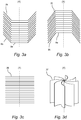
- Fig. 3a-d shows a few examples of separation discs that may be used in a centrifugal separator of the present disclosure. For clarity reasons, only a few discs are illustrated and it is to be understood that in reality, a larger number of discs are present so that the distance between the discs is much smaller.
- Fig. 3a shows an example of frustoconical discs 35 having a planar portion 9a and a frustoconical portion 9b.
- the planar portion 9a extends in a plane that is perpendicular to the axis of rotation (X), and the frustoconical portion 9b extends in this embodiment upwards.
- the planar portion 9a is closer to the rotational axis than the frustoconical portion 9b.
- the planar portion 9a and/or the frustoconical portion 9b may comprise through holes for gas.
- Fig. 3b shows an example of frustoconical discs 35 having a planar portion 9a and a frustoconical portion 9b.
- the planar portion 9a extends in a plane that is perpendicular to the axis of rotation (X), and the frustoconical portion 9b extends in this embodiment downwards.
- the planar portion 9a is closer to the rotational axis than the frustoconical portion 9b.
- the planar portion 9a and/or the frustoconical portion 9b may comprise through holes for gas.
- Fig. 3c shows an example of a disc stack in which all discs 36 are planar, i.e. all discs 36 extend in the plane that is perpendicular to the axis of rotation (X).
- the discs 36 may comprise through holes for gas.
- Fig. 3d shows an example of axial discs or plates 37.
- These plates 37 are slightly curved, i.e. they have a curved shaped as seen in a radial plane. In other words, they are curved as seen in a plane that is perpendicular to the axis of rotation (X).
- the axial discs 37 may comprise through holes for gas.
- centrifugal separator also comprises centrifugal separators with a substantially horizontally oriented axis of rotation.
Landscapes
- Engineering & Computer Science (AREA)
- Mechanical Engineering (AREA)
- General Engineering & Computer Science (AREA)
- Chemical & Material Sciences (AREA)
- Chemical Kinetics & Catalysis (AREA)
- Centrifugal Separators (AREA)
- Lubrication Details And Ventilation Of Internal Combustion Engines (AREA)
- Separating Particles In Gases By Inertia (AREA)
Description
- The present invention relates to the field of centrifugal separators for cleaning a gas containing liquid impurities. In particular, the present invention relates to cleaning crankcase gases of a combustion engine from oil particles.
- It is well known that a mixture of fluids having different densities may be separated from one another through use of a centrifugal separator. One specific use of such a separator is in the separation of oil from gas vented from a crankcase forming part of an internal combustion engine.
- With regard to this specific use of separators, there can be a tendency for the high pressure gas found in the combustion chambers of an internal combustion engine to leak past the associated piston rings and into the crankcase of the engine. This continuous leaking of gas into the crankcase can lead to an undesirable increase of pressure within the crankcase and, as a consequence, to a need to vent gas from the casing. Such gas vented from the crankcase typically carries a quantity of engine oil (as droplets or a fine mist), which is picked up from the reservoir of oil held in the crankcase.
- In order to allow vented gas to be introduced into the inlet system without also introducing unwanted oil (particularly into a turbocharging system wherein the efficiency of the compressor can be adversely affected by the presence of oil), it is necessary to clean the vented gas (i.e. to remove the oil carried by the gas) prior to the gas being introduced into the inlet system. This cleaning process may be undertaken by a centrifugal separator, which is mounted on or adjacent the crankcase and which directs cleaned gas to the inlet system and directs separated oil back to the crankcase. An example of such a separator is disclosed e.g. in
US 8,657,908 . The centrifugal separator may be driven by e.g. a turbine wheel, rotated by means of an oil jet from the lubrication oil system of the combustion engine, or by an electrical motor. - However, a diesel engine on e.g. a truck may have a varied workload, everything between an idling engine at standstill to full torque when driving up a hill fully loaded. Thus, there is a need in the art for convenient arrangements that can adapt the operation of the centrifugal separator to the engine's demand for cleaning the crankcase gas.
- A centrifugal separator according to the preamble of
claim 1 is known fromEP 1 532 352 A1 - A main object of the present invention is to provide an electrically driven centrifugal separator for cleaning gas having a simplified operational control.
- As a first embodiment of the invention, there is provided a centrifugal separator according to
claim 1. - The contaminants in the gas may comprise liquid impurities, such as oil, and soot.
- Consequently, the centrifugal separator may be for separating liquid impurities, such as oil, from gas. The gas may be crankcase gas of a combustion engine. Thus, the centrifugal separator may be adapted for cleaning crankcase gas from a diesel engine, such as a diesel engine on a truck. The separator may further be adapted to be fitted onto an engine, such as a diesel engine. However, the centrifugal separator may also be suitable for cleaning gases from other sources, for instance the environment of machine tools which frequently contains large amounts of liquid impurities in the form of oil droplets or oil mist.
- The stationary casing of the centrifugal separator may comprise a surrounding side wall, and first and second end walls, which enclose the separation space. The stationary casing may have a cylindrical shape with circular cross-section having a radius R from the axis (X) of rotation to the surrounding side wall. This radius R may be constant at least with respect to a major part of the circumference of the surrounding side wall. The stationary casing may also be slightly conical. The first and second end walls may thus form an upper end wall and a lower end wall of the cylindrical shaped casing.
- The gas inlet of the centrifugal separator may be located through the first end wall or through the surrounding side wall close to the first end wall, thus at the top of the separator, such that gas entering through the gas inlet is directed to the separation space. The drainage outlet may be located in the second end wall, e.g. at the bottom of the separator. Thus, the drainage outlet may be arranged centrally in an end wall opposite the end wall through which, or at which, the inlet is arranged. The drainage outlet of the centrifugal separator may further be formed by a number of spot shaped through holes of the stationary casing or by a single drainage passage. The drainage outlet may be arranged at the axis of rotation or centered on the axis of rotation. The drainage outlet may also be in an annular collection groove at the inner end wall of the stationary casing. The gas outlet may be arranged in a surrounding side wall of the stationary casing or may for example be arranged in an end wall, such as the end wall opposite the end wall through which, or at which, the gas inlet is arranged.
- The rotating member is arranged for rotation during operation by means of the electrical motor. The rotating member comprises a plurality of separation members arranged in the separation space. The separation members of the rotating member are examples of surface-enlarging inserts that promote separation of contaminants from the gas. The separation members may be a stack of separation discs. The separation discs of the stack may be frustoconical. A frustoconical disc may have a planar portion extending in a plane that is perpendicular to the axis of rotation, and a frustoconical portion that may extend upwards or downwards. The planar portion may be closer to the rotational axis than the frustoconical portion. Further, the discs of the stack may be radial discs, in which substantially the whole disc extends in a plane that is perpendicular to the axis of rotation.
- It is also to be understood that the separation members, such as separation discs, not necessarily have to be arranged in a stack. The separation space may for example comprise axial discs, or plates that extend around the axis of rotation. The axial discs or plates may be planar, i.e. extending in planes that are parallel to the axis of rotation. The axial discs or plates may also have a slightly or significantly curved shape, such as an arcuate or spiral shape, as seen in a radial plane.
- During operation, gas to be cleaned may be directed centrally through the plurality of separation members, such as centrally through the stack of separation discs. In such a set-up, the rotating member may further define a central space formed by at least one through hole in each of the separation members. This central space is connected to the gas inlet and configured to convey the gas to be cleaned from the gas inlet to the gaps between the separation members, such as between the gaps between the discs of a stack of separation discs. A separation disc that may be used as separation member may comprise a central, essentially flat portion perpendicular to the axis of rotation. This portion may comprise the through holes that form the central space.
- Thus, the centrifugal separator may be configured to lead crankcase gases from the gas inlet into a central portion of the rotating member. In this manner the crankcase gases may be "pumped" from the central portion of the rotating member into the interspaces between the separation discs in the stack of separation discs by the rotation of the rotating member. Thus, the centrifugal separator may work according to the concurrent flow principle, in which the gas flows in the disc stack from a radial inner part to a radial outer part, which is opposite to a separator operating according to the counter-current flow principle, in which the gas is conducted into the centrifugal rotor at the periphery of the rotor and is led towards a central part of the rotor.
- The electrical motor may principally be of any suitable kind, for instance a direct-current motor or an alternate-current motor (synchronous motor or asynchronous motor). As an example, the electrical motor may be a synchronous motor, such as a brushless electric motor, having a rotor that includes permanent magnets.
- The electrical motor may be arranged within the stationary casing or outside the stationary casing.
- Furthermore, an electrical motor which does not have separate bearings for the journalling of the rotor of the motor may be used. The already present and necessary bearings for the rotating part may instead be used for this journalling. As an example, the electrical motor may be arranged within the stationary casing and have a stator that is supported by the stationary casing, and a rotor, that is constituted by part of the rotating member of the centrifugal separator and which is journalled relative to the stator only through the bearings.
- Such a configuration is for example explained in more detail in the international patent application published as
WO 2004/001201 . - The centrifugal separator further comprises a control unit configured to control the operation of the electrical motor. The control unit may comprise a processor and an input/output interface for communicating with the electrical motor and for receiving information from e.g. other parts of the separator, such as from sensors arranged on the separator, and/or from e.g. an engine to which the centrifugal separator is connected or mounted.
- The control unit is at least able to control the electrical motor so that it may drive the separator in at least two operational modes. The operational modes are different from each other, and the control unit may be configured to drive the centrifugal separator in at least two, such as at least three, such as at least four different operational modes. Thus, the control equipment may be configured for driving the electrical motor at different speeds. The control unit may thus be in the same unit as the electrical motor, which may be arranged within the stationary casing or outside the stationary casing. However, the control unit may also be a separate unit than the electrical motor. Thus, the control unit may be a separate unit arranged outside the stationary casing whereas the electrical motor is arranged within the stationary casing, or as an alternative, both the electrical motor and the control unit are arranged outside the stationary casing, but as different units.
- The control unit is also configured to switch between such operational modes based on received information of at least one measured internal parameter of the electrical motor. An "internal parameter" is related to the actual operation of the electrical motor and may be a parameter that can vary in time during operation of the electrical motor. Thus, the control unit may be configured to drive the electrical motor in a first operational mode and to measure at least one internal parameter on a continuous basis. If the value of the measured parameter indicates a switch in operational modes, e.g. if the measured value is above or below a certain threshold or within a specific interval, the control unit may switch to drive the electrical motor in another operational mode. However, the control unit may be configured not to switch between operational modes immediately but instead wait to see the temporal behavior of the measured parameter. As an example, if the value of measured internal parameter indicates a switch in operational modes, the control unit may wait a certain time period, such as between 5-30 s, such as between 5-15 s, and if the value of the measured internal parameter still indicates a switch, the control unit may then switch to another operational mode.
- The time during which the centrifugal separator is operated in different modes may of course vary and depends on the information of the at least one measured internal parameter.
- The control unit is configured to switch between operational modes depending solely on one or several of such internal parameters, and may also be configured to switch between operational modes depending on one or several of such internal parameters in combination with "external parameters", i.e. parameters that may be related to other parts of the centrifugal separator or to an engine to which the separator is mounted.
- Consequently, the centrifugal separator according to the invention is operating in different operational modes and the switch between modes is based at least on internal parameters of the electrical motor. The first aspect of the invention is based on the insight that a separator for treatment of crankcase gas could be controlled into two or more operational modes, such as at two or more pre-determined speeds or two or more pre-determined torque levels. If the separator could automatically adjust e.g. its speed or torque from a nominal level to e.g. one lower and/or one higher level, the separator's workload could be fairly well adapted to an engine's demand for cleaning the crankcase gas. Further, the inventor has found that by measuring one or several internal parameters of the electrical motor driving the separator, it is possible to determine if the separator should remain running at the nominal operational model or be shifted to run in a different mode. It is advantageous to use internal parameters of the electrical motor for controlling the shift between operational modes since they are easily accessible, i.e. the electrical motor does not require the use of external sensors, wires and/or connections to other parts of e.g. the separator or engine to which the separator is mounted for regulating the operation of the separator.
- At least two different operational modes are at least two different driving modes of the electrical motor in which either the torque or the rotational speed of the electrical motor is kept at different constant levels.
- Thus, the control unit is configured to switch between a first constant speed or torque level and depending on the measured internal parameter of the electrical motor, shift to at least one further constant speed or torque level, such as to a second speed or torque level. The control unit may be configured to shift between several different constant speed or torque levels, such as to shift between two, three, four or five or more constant speed or torque levels.
- Consequently, the at least two different driving modes comprises at least two different speed levels in which the rotational speed is kept at different constant levels.
- The different speed levels may be constant levels that differ more than 10%, such as more than 20%, such as more than 30%, such as more than 50%.
- The different speed levels may be constant levels that differ more than 2000 rpm, such as more than 3000 rpm, such as more than 4000 rpm.
- Further, the at least two different driving modes comprise a first speed level at a first constant rotational speed and a second speed level at a second constant rotational speed, wherein the second constant rotational speed is higher than the first constant rotational speed, and wherein the control unit is configured to switch to the second speed level if the at least one measured internal parameter indicates that there is a higher demand for cleaning the gas when running at the first speed level.
- The first constant rotational speed may thus be a nominal speed of the centrifugal separator, whereas the second rotational speed may be a higher speed that is used when there is an increased need for cleaning of crankcase gas.
- The first constant rotational speed may thus comprise rotating the rotating member at a speed of between 7.500 and 12.000 rpm, and the second constant rotational speed may be a speed that is more than 10% higher than the first constant rotational speed, such as more than 2000 rpm higher than the first constant rotational speed.
- However, it is to be understood that the at least two driving modes may comprise a plurality of different speed levels, such as more than three different speed levels, such as more than five different speed levels.
- Further, the at least two different driving modes may further comprise a third speed level at a third constant rotational speed, wherein the third constant rotational speed is lower than the first constant rotational speed, and wherein the control unit is configured to switch to the third speed level if the at least one measured internal parameter indicates that there is a lower demand for cleaning the gas when running at the first speed level.
- The third constant rotational speed may be a speed that is more than 2000 rpm lower than the first constant rotational speed, and may thus be used when there is a decreased need for cleaning of crankcase gas. Such decreased need may for example be when the engine to which the centrifugal separator is mounted is at standstill.
- In embodiments of the first aspect of the invention, at least two different driving modes comprises at least two different torque levels in which the torque of the electrical motor is kept at different constant levels.
- Thus, the control unit may be configured to operate at fixed torque levels whereas the rotational speed may be vary in the different driving modes. As discussed in relation to the different speed levels above, the at least two different driving modes may comprise a first torque level, i.e. a nominal torque level used during normal driving, a second torque level higher than the first level and used when there is an increased need for cleaning of crankcase gas and optionally also a third torque level lower than the first torque level and used when there is a decreased need for cleaning of crankcase gas. However, it is to be understood that the at least two driving modes may comprise a plurality of different torque levels, such as more than three different torque levels, such as more than five different torque levels.
- In embodiments of the first aspect of the invention, at least one measured internal parameter of the electrical motor is the electric power consumption of the electrical motor or the electric current through the electrical motor.
- Thus, an internal parameter may be or comprise information of the electric power consumption, e.g. absolute power consumption per unit time. The internal parameter may also be the electric current through the electric motor, which thus is linked to the power consumption. The electric current may for example be an absolute amount of current per time unit. The power consumption and the electric current through the electrical motor may increase when there is a higher demand for cleaning of crankcase gas.
- In embodiments of the first aspect of the invention, at least one measured internal parameter of the electrical motor is the temporal fluctuations of the electric current through the electrical motor.
- The temporal fluctuations of the electric current may be "ripples" in the signal corresponding to the electric current, and may be fluctuations measured that occur in less than a second. The temporal fluctuations may be small periodic variations in the current. It is believed that the temporal fluctuations of the electric current is different when there is a low demand for cleaning of crankcase gas compared to when there is a high demand for cleaning of crankcase gas.
- In embodiments of the first aspect of the invention, at least one measured internal parameter of the electrical motor is the temperature of the electrical motor.
- Thus, there temperature of the electrical motor may be different when there is a low demand for cleaning of crankcase gas compared to when there is a high demand for cleaning of crankcase gas, and may thus be used as an internal parameter of the electrical motor for regulating in which operational mode the separator should be operated.
- In embodiments of the first aspect of the invention, at least one measured internal parameter of the electrical motor is the time from startup of the electrical motor.
- Thus, the control unit may be adapted to register the operating time of the electrical motor, and use this parameter to regulate in which operational mode the separator should be operated. As an example, the control unit may be configured to run the separator in an operational mode related to low demand for cleaning the crankcase gas during a time period from startup of the electrical motor. This time period may correspond to a time period from startup of the engine to which the separator is mounted, i.e. a time period during which the engine is idling.
- In embodiments of the first aspect of the invention, the control unit is further adapted to switch between operational modes depending at least on information from at least one measured internal parameter of the electrical motor and on information of at least one external parameter.
- Thus, the control unit may be configured to regulate operating the separator in the different operational modes based both on information about internal parameters of the electrical motor, as discussed above, and on information about one or several external parameters. External parameters may be parameters that are not related to the actual driving of the electrical motor, such as parameters related to the engine to which the separator is mounted or to the actual separator. Thus, the centrifugal separator may comprise one or several sensors for measuring such external parameters and sending information to the control unit about the measured parameter. The sensors may comprise a sensor registering a pressure at the gas inlet and/or gas outlet of the separator.
- As an example, at least one external parameter is selected from the pressure at the gas inlet or the temperature of the gas inlet. Thus, the centrifugal separator may comprise a pressure sensor and/or a temperature sensor at the gas inlet, and the control unit may be configured to receive a signal related to the gas pressure and/or temperature at the gas inlet, and regulate driving the separator in the different operational modes depending on at least one internal parameter of the electrical motor and the received information about the gas pressure and/or temperature at the gas inlet.
- At least one external parameter may also comprise information related to the age of the engine to which the separator is mounted, since an old engine usually produces more crankcase gas. Thus, in embodiments, the control unit is configured to receive a signal that is related to the time during which an engine to which the centrifugal separator may be connected has been running. The control unit may therefore be configured to take into account the age of the engine when regulating the electrical motor, e.g. so that the electrical motor is driven in an operational mode that represents an increased cleaning of crankcase gas if the engine is old compared to if the engine is new. As an example, if the operational modes are driving modes at different constant speed levels, these constant speed levels may be shifted to higher constant rotational speed levels if the control unit receives information that the engine is above a certain age.
- However, it is also to be understood that the control unit may be configured to switch between operational modes depending solely on information of at least one measured internal parameter of the electrical motor.
- As a second aspect of the invention, there is provided a method for cleaning gas comprising contaminants, comprising the steps of
- providing a centrifugal separator according to the first aspect above,
- running the centrifugal separator by driving the electrical motor in a first operational mode,
- measuring at least one internal parameter of the electrical motor, and
- switching the electrical motor to drive in a second operational mode depending at least on information of the least one measured internal parameter of the electrical motor.
- Terms and definitions used in relation to the second aspect of the invention are as discussed in relation to the first aspect of the invention above.
- The step of running the centrifugal separator comprises rotating the rotating member of the centrifugal separator.
- The method may further comprise the steps of
- introducing gas containing contaminants into gas inlet of the centrifugal separator; and
- discharging cleaned gas through the gas outlet of the centrifugal separator and discharging contaminants separated from the gas through the drainage outlet of the centrifugal separator.
- In embodiments of the second aspect of the invention, the method is further comprising
- switching back to driving in the first operational mode depending at least on information of the least one measured internal parameter of the electrical motor.
- Thus, during operation of the centrifugal separator, i.e. during running of the engine to which the separator is mounted, the separator may switch back and forth between operational modes, such as back and forth between different speed levels depending on the need for cleaning of crankcase gas, as discussed in relation to the first aspect above.
- In embodiments of the second aspect of the invention, a step of switching to another operational mode also depends on information of at least one external parameter.
- Thus, as discussed in relation to the first aspect above, the step of switching between operational modes may depend both on internal parameters of the electrical motor and on external parameter, such as the gas pressure and/or temperature at the gas inlet of the centrifugal separator.
-
-
Figure 1 shows a section of an embodiment of a centrifugal separator. -
Figure 2 shows a section of an embodiment of a centrifugal separator. -
Figure 3a-d show different types of separation members that may be used in the centrifugal separator. - The centrifugal separator and method according to the present disclosure will be further illustrated by the following description with reference to the accompanying drawings.
-
Fig. 1 shows a section of acentrifugal separator 1 of the separator arrangement. Thecentrifugal separator 1 comprises astationary casing 2, which is configured to be mounted to a combustion engine (not disclosed), especially a diesel engine, at a suitable position, such as on top of the combustion engine or at the side of the combustion engine. - It is to be noted that the
centrifugal separator 1 is also suitable for cleaning gases from other sources than combustion engines, for instance the environment of machine tools which frequently contains large amounts of liquid impurities in the form of oil droplets or oil mist. - The
stationary casing 2 encloses aseparation space 3 through which a gas flow is permitted. Thestationary casing 2 comprises, or is formed by, a surroundingside wall 4, a first end wall 5 (in the embodiments disclosed an upper end wall) and a second end wall 6 (in the embodiments disclosed a lower end wall). - The centrifugal separator comprises a rotating
member 7, which is arranged to rotate around an axis x of rotation. It should be noted that thestationary casing 2 is stationary in relation to the rotatingmember 7, and preferably in relation to the combustion engine to which it may be mounted. - The
stationary casing 2 has a radius from the axis x of rotation to the surroundingside wall 4 that is constant at least with respect to a major part of the circumference of the surroundingside wall 4. The surroundingside wall 4 thus has a circular, or substantially, circular cross-section. - The rotating
member 7 comprises aspindle 8 and a stack ofseparation discs 9 attached to thespindle 8. All the separation discs of thestack 9 are provided between a first end plate 10 (in the embodiment disclosed an upper end plate) and a second end plate 11 (in the embodiment disclosed a lower end plate). - The
spindle 8, and thus the rotatingmember 7, is rotatably supported in thestationary casing 2 by means of a first bearing 12 (in the embodiment disclosed as an upper bearing) and a second bearing 13 (in the embodiments disclosed ass a lower bearing), the bearings being arranged one on each side of the stack ofseparation discs 9. Theupper bearing 12 is supported by acap 19 which by a cylindrical part surrounds an upper end portion of the centrifugal rotor shaft, i.e. thespindle 8, the upper end portion being situated axially above theupper bearing 12. Thecap 19 also has an annularplain portion 20, through which the cap is supported by apartition 21 in thestationary casing 2. The plainannular portion 20 of thecap 19 is provided with throughholes 22, through which theinlet conduit 18 communicates with thecentral space 15. - Axially above the
upper bearing 12 thecap 19 supports on its inside, around the end portion of thespindle 8, astator 24 belonging to anelectrical motor 23. Arotor 25 belonging to thiselectrical motor 23 is supported by the end portion of the centrifugal rotor shaft, i.e. thespindle 8. A narrowannular slot 26 is formed between themotor stator 24 and themotor rotor 25. As can be seen, theelectrical motor 23 in this embodiment has no bearings of its own, through which itsrotor 25 would be rotatably journalled in itsstator 24. Instead, the twobearings member 7 is journalled in thestationary casing 2, are utilized for the journalling of therotor 25 of theelectrical motor 23. - The separation discs of the
stack 9 are frusto-conical and extend outwardly and upwardly from thespindle 8. The separation discs thus comprise aflat portion 9a, which extend perpendicularly to the axis of rotation X, and aconical portion 9b, that extend outwardly and upwardly from theflat portion 9a. - It should be noted that the separation discs also could extend outwardly and downwardly, or even radially.
- The separation discs of the
stack 9 are provided at a distance from each other by means of distance members (not disclosed) in order to formgaps 14 betweenadjacent separation discs 9, i.e. agap 14 between each pair ofadjacent separation discs 9. The axial thickness of eachgap 14 may e.g. be in the order of 1-2 mm. - The separation discs of the
stack 9 may be made of plastic or metal. The number of separation discs in thestack 9 is normally higher than indicated inFig. 1 and may be for instance 50 to 100separation discs 9 depending of the size of the centrifugal separator. - The rotating
member 7 defines acentral space 15. Thecentral space 15 is formed by a hole in each of theseparation discs 9. In the embodiments ofFig. 1 , thecentral space 15 is formed by a plurality of throughholes 16, each extending through thefirst end plate 10 and through each of theseparation discs 9, but not through thesecond end plate 11. The through holes are arranged in theflat portions 9a of the separation discs. - The
centrifugal separator 1 comprises agas inlet 17 for the supply of the gas to be cleaned. Thegas inlet 17 extends through thestationary casing 2, and more precisely through thefirst end wall 5. Thegas inlet 17 communicates with thecentral space 15 so that the gas to be cleaned is conveyed from theinlet 17 via thecentral space 15 to thegaps 14 of the stack ofseparation discs 9. Thegas inlet 17 is configured to communicate with the crankcase of the combustion engine, or any other source, via aninlet conduit 18 permitting the supply of crankcase gas from the crankcase to thegas inlet 17 and further to thecentral space 15 and thegaps 14 as explained above. - The centrifugal separator comprises a
drainage outlet 29 configured to permit discharge of liquid impurities separated from the gas and agas outlet 30 configured to permit discharge of cleaned gas. The drainage outlet is in this embodiment arranged as a conduit in thesecond end wall 6, but thedrainage outlet 29 may also be in the form of through holes arranged in thelower end wall 6 so that separated liquid impurities flow through thesecond bearing 13 as they are drained from theseparation space 3. Furthermore, thegas outlet 30 is in this embodiment arranged in thesecond end wall 6 at a radial distance that is shorter than the radial distance to thedrainage outlet 2, but the gas outlet could also be arranged e.g. in the surroundingside wall 4. - By means of
control unit 28, the rotational speed and thereby the cleaning efficiency of the centrifugal separator may be controlled in a suitable way so that a required cleaning of the supplied gas is obtained. This is achieved by means ofconnection 27, which extend into thecasing 1 and further through thecap 14 in to thestator 18 of the motor. Thisconnection 27 could also be used for charging theelectrical motor 23 with current. Thecontrol unit 30 includes a device for driving theelectrical motor 23 at different speeds. Different kinds of devices for speed regulation of motors (both direct-current and alternate-current motors) are well known. For a direct-current motor a simple device for voltage control may be used. For an alternate-current motor various kinds of frequency control equipment may be used. - The
control unit 28 may further comprise acommunication interface 31, such as a transmitter/receiver, via which it may receive data from the electrical motor and various sensors or the engine to which the separator is connected and further transmit data to theelectrical motor 23. - The received data may for instance include data on a measured pressure from a
pressure sensor 32 at thegas inlet 17, as indicated by dotted arrow "A. The transmitted data may for instance include a control signal for controlling the speed of theelectrical motor 23. - The
control unit 28 is further configured to carry out a method for controlling theelectrical motor 28 according to embodiments disclosed herein. For this purpose thecontrol unit 28 may comprise aprocessing unit 33, such as a central processing unit, which is configured to execute computer code instructions which for instance may be stored on amemory 34. Thememory 34 may thus form a (non-transitory) computer-readable medium for storing such computer code instructions. Theprocessing unit 33 may alternatively be in the form of a hardware component, such as an application specific integrated circuit, a field-programmable gate array or the like. - In this embodiment, the
control unit 28 is a separate unit from thecentrifugal separator 1. However, the control unit may also be a part of the separator, such as forming a part of theelectrical motor 23. Thus, the control unit with all its functions could be arranged at the electrical motor, such as being connected to thestator 24 supported by thecap 19. - During operation, the rotating
member 17 is kept in rotation by supply of current to theelectrical motor 23 and contaminated gas, e.g. crankcase gas from the crankcase of an internal combustion engine, is supplied to thegas inlet 17 viaconduit 18. This gas is conducted further into thecentral space 15 and from there into and through theinterspaces 14 between the separation discs of thestack 9. As a consequence of the rotation of the rotatingmember 7 the gas is brought to rotate, whereby it is pumped further on radially outwardly through gaps or interspaces 14. - During the rotation of the gas in the interspaces solid or liquid particles suspended in the gas are separated therefrom. The particles settle on the insides of the
conical portions 9b of the separation discs and slide or run after that radially outwardly thereon. When the particles and/or liquid drops have reached out to the outer edges of the separation discs, they are thrown away from the rotor and hit the inner surface of the surroundingwall 4 of thestationary casing 2. The particles continue downwardly along this wall and leave theseparation space 3 through thedrainage outlet 29, whereas the gas freed from particles and exiting from the stack ofseparation discs 9 leaves thecasing 1 through thegas outlet 30. The path of the gas through thecentrifugal separator 1 is schematically shown by arrows "C" inFig. 1 . - As discussed above, the
control unit 28 controls the rotational speed of the rotating part by sending signal to theelectrical motor 23. In this embodiment, the control unit is configured to control the electrical motor to drive at three different drive modes; a first drive mode having a first constant rotational speed of between 7.500 and 12.000 rpm and which represents a nominal speed of the separator, a second drive mode having a second constant rotational speed that is about 2000 rpm above the first constant rotational speed and a third drive mode having a third constant rotational speed that is about 2000 rpm below the first constant rotational speed. - The following example illustrates how the centrifugal separator operates by switching back and forth between the three driving modes depending on the measured electric current through the
electrical motor 23 when thecentrifugal separator 1 is connected to a diesel engine of a truck: - As the truck engine is started up, the
control unit 28 drives theelectrical motor 23 at the first drive mode, i.e. it speeds up to the nominal speed. As the truck engine is idling and the amount of crankcase gas is low the current through theelectrical motor 23 is lower, such as below a predetermined threshold. Thecontrol unit 28 has further information of the time since starting theelectrical motor 23, and based on these information it regulates the electrical motor to drive in the third drive mode, i.e. at a lower constant rotational speed since the amount of crankcase gas produce is relatively low. - As the truck begins to move, the amount of crankcase gas increases. Consequently the current through the
electrical motor 23 increases to keep the actual third constant rotational speed. When getting information of the increased current through theelectrical motor 23, thecontrol unit 28 regulates theelectrical motor 23 so that it operates in the first drive mode, i.e. so that it rotates in its nominal speed at the first constant speed level. - If the truck enters the foot of a hill and starts to climb the engine's torque increases. This in turn means that the amount of crankcase gas increases, which leads to a higher power consumption and thus a higher current through the
electrical motor 23 to keep the rotational speed at the first constant speed level. In this case, thecontrol unit 28 receives constant information about the increased current through theelectrical motor 23 and if the current still is increased after also after a certain time period, such as 10 s, after detecting the start of the increase in current, thecontrol unit 28 regulates theelectrical motor 23 so that it operates in the second drive mode, i.e. so that it rotates at the second constant speed level that is above the nominal speed. - The truck has now climbed the hill and the amount of crankcase gas is normal again. Hence, the measured current through the electrical motor is decreased and the control unit regulates the
electrical motor 23 so that it yet again operates in the first drive mode, i.e. so that it rotates in its nominal speed at the first constant speed level. - When the truck stands still, the control unit receives information that a decreased current through the
electrical motor 23 is needed to keep the rotational speed at the first constant speed level. If the measured current still is decreased after also after a certain time period, such as 10 s, after detecting the start of the decrease in current, thecontrol unit 28 regulates theelectrical motor 23 so that it operates in the third drive mode again, i.e. so that it rotates at the third constant speed level that is below the nominal speed. - In the above example, the switch between the different speed levels is based solely on the internal parameter of the
electrical motor 23, i.e. the current through the electrical motor, but thecontrol unit 28 may also in addition use information fromsensor 32, i.e. information from the gas pressure at thegas inlet 17, for deciding if the speed level should be switched. As an example, the control unit may switch to a higher speed level if the measured current through theelectrical motor 23 and the gas pressure at the gas inlet increases, and may switch to a lower speed level if the measured current through the electrical motor and the gas pressure at the gas inlet decreases, - An
electrical motor 23 of the kind shown inFig. 1 may alternatively be arranged around an extension of thespindle 8 below thelower bearing 13. It is also possible to arrange the motor in a space axially between theupper bearing 12 and thefirst end plate 10 or axially between thelower bearing 13 and thesecond end plate 11. An electrical motor having a disc-formed circular rotor and a stator formed so that it is situated axially on both sides of the rotor may also be used. -
Fig. 2 shows an example of an embodiment of a centrifugal separator in which theelectrical motor 23 is arranged on an extension of thespindle 8 axially above theupper wall 5 of thestationary casing 2. As an alternative, theelectrical motor 23 could also be arranged on an extension of thespindle 8 axially below thelower end wall 6 of thestationary casing 2. - Thus, in the embodiment shown, the stator and the rotor of the
electrical motor 23 are arranged outside thestationary casing 2. Further, thecontrol unit 28 is arranged as a part of theelectrical motor 23, but functions as discussed in relation to the embodiment shown inFig. 1 . All other functions are the same as discussed in relation to the embodiment shown inFig. 1 , i.e. the reference numerals denote the same features. - In the embodiments shown in
Fig. 1 andFig. 2 , the rotatingmember 7 for the gas cleaning is provided with a stack of conical separation discs of a conventional kind. However, the invention is not limited to a rotating member or centrifugal rotor of precisely this kind but may be used in connection with any suitable centrifugal rotor for freeing a gas from particles suspended therein. -
Fig. 3a-d shows a few examples of separation discs that may be used in a centrifugal separator of the present disclosure. For clarity reasons, only a few discs are illustrated and it is to be understood that in reality, a larger number of discs are present so that the distance between the discs is much smaller. -
Fig. 3a shows an example offrustoconical discs 35 having aplanar portion 9a and afrustoconical portion 9b. Theplanar portion 9a extends in a plane that is perpendicular to the axis of rotation (X), and thefrustoconical portion 9b extends in this embodiment upwards. Theplanar portion 9a is closer to the rotational axis than thefrustoconical portion 9b. Theplanar portion 9a and/or thefrustoconical portion 9b may comprise through holes for gas. -
Fig. 3b shows an example offrustoconical discs 35 having aplanar portion 9a and afrustoconical portion 9b. Theplanar portion 9a extends in a plane that is perpendicular to the axis of rotation (X), and thefrustoconical portion 9b extends in this embodiment downwards. Theplanar portion 9a is closer to the rotational axis than thefrustoconical portion 9b. Theplanar portion 9a and/or thefrustoconical portion 9b may comprise through holes for gas. -
Fig. 3c shows an example of a disc stack in which alldiscs 36 are planar, i.e. alldiscs 36 extend in the plane that is perpendicular to the axis of rotation (X). Thediscs 36 may comprise through holes for gas. -
Fig. 3d shows an example of axial discs orplates 37. Theseplates 37 are slightly curved, i.e. they have a curved shaped as seen in a radial plane. In other words, they are curved as seen in a plane that is perpendicular to the axis of rotation (X). Theaxial discs 37 may comprise through holes for gas. - The invention is not limited to the embodiment disclosed but may be varied and modified within the scope of the claims set out below. The invention is not limited to the orientation of the axis of rotation (X) disclosed in the figures. The term "centrifugal separator" also comprises centrifugal separators with a substantially horizontally oriented axis of rotation.
Claims (11)
- A centrifugal separator (1) for cleaning gas containing contaminants, said gas being crankcase gas of a combustion engine, said centrifugal separator comprisinga stationary casing (2), enclosing a separation space (3) through which a gas flow is permitted,a gas inlet (17) extending through the stationary casing and permitting supply of the gas to be cleaned,a rotating member (7) comprising a plurality of separation members (9, 35; 36; 37) arranged in said separation space (3) and being arranged to rotate around an axis (X) of rotation,a gas outlet (30) configured to permit discharge of cleaned gas and comprising an outlet opening through a wall of the stationary casing,a drainage outlet (29) configured to permit discharge of liquid impurities separated from the gas to be cleaned, andan electrical motor (23), for rotating the rotating member (7);characterized in that the centrifugal separator (1) further comprises a control unit (28) which is configured to control the operation of the electrical motor (23) and to drive the electrical motor in at least two different operational modes and to further switch between operational modes depending at least on information of at least one measured internal parameter of the electrical motor.wherein the at least two different operational modes are at least two different driving modes of the electrical motor (23) in which either the torque or the rotational speed of the electrical motor is kept at different constant levels, and wherein the at least two different driving modes comprise at least two different speed levels in which the rotational speed is kept at different constant levels, and wherein the at least two different driving modes comprise a first speed level at a first constant rotational speed and a second speed level at a second constant rotational speed, wherein the second constant rotational speed is higher than the first constant rotational speed, and wherein the control unit (28) is configured to switch to said second speed level if the at least one measured internal parameter indicates that there is a higher demand for cleaning the gas when running at the first speed level.
- A centrifugal separator (1) according to claim 1, wherein the at least two different driving modes further comprise a third speed level at a third constant rotational speed, wherein the third constant rotational speed is lower than the first constant rotational speed, and wherein the control unit (28) is configured to switch to said third speed level if the at least one measured internal parameter indicates that there is a lower demand for cleaning the gas when running at the first speed level.
- A centrifugal separator (1) according to any previous claim, wherein at least one measured internal parameter of the electrical motor is the electric power consumption of the electrical motor or the electric current through the electrical motor.
- A centrifugal separator (1) according to any previous claim, wherein at least one measured internal parameter of the electrical motor is the temporal fluctuations of the electric current through the electrical motor.
- A centrifugal separator (1) according to any previous claim, wherein at least one measured internal parameter of the electrical motor is the temperature of the electrical motor.
- A centrifugal separator (1) according to any previous claim, wherein at least one measured internal parameter of the electrical motor is the time from startup of the electrical motor.
- A centrifugal separator (1) according to any previous claim, wherein the control unit (28) is further adapted to switch between operational modes depending at least on information from at least one measured internal parameter of the electrical motor and on information of at least one external parameter.
- A centrifugal separator (1) according to claim 7, wherein at least one external parameter is selected from the pressure at the gas inlet (17) or the temperature of the gas inlet (17).
- A method for cleaning crankcase gas of a combustion engine, comprising the steps of- providing a centrifugal separator (1) according to any previous claim,- running the centrifugal separator (1) by driving the electrical motor (23) in a first operational mode,- measuring at least one internal parameter of the electrical motor (23), and- switching the electrical motor (23) to drive in a second operational mode depending at least on information of the least one measured internal parameter of the electrical motor.
- A method according to claim 9, further comprising- switching back to driving in said first operational mode depending at least on information of the least one measured internal parameter of the electrical motor.
- A method according to claim 9 or 10, wherein a step of switching to another operational mode also depends on information of at least one external parameter.
Priority Applications (8)
| Application Number | Priority Date | Filing Date | Title |
|---|---|---|---|
| EP16185689.3A EP3287193B1 (en) | 2016-08-25 | 2016-08-25 | Control of a centrifugal separator |
| JP2019510923A JP7149931B2 (en) | 2016-08-25 | 2017-08-17 | Centrifuge control |
| US16/321,298 US11313262B2 (en) | 2016-08-25 | 2017-08-17 | Control of a centrifugal separator |
| KR1020197008013A KR20190040283A (en) | 2016-08-25 | 2017-08-17 | Control of centrifuge |
| BR112019001548-5A BR112019001548B1 (en) | 2016-08-25 | 2017-08-17 | CENTRIFUGAL SEPARATOR AND, METHOD FOR GAS CLEANING |
| RU2019108083A RU2720375C1 (en) | 2016-08-25 | 2017-08-17 | Centrifugal separator control |
| CN201780051602.1A CN109562392B (en) | 2016-08-25 | 2017-08-17 | Control of a centrifugal separator |
| PCT/EP2017/070864 WO2018036906A1 (en) | 2016-08-25 | 2017-08-17 | Control of a centrifugal separator |
Applications Claiming Priority (1)
| Application Number | Priority Date | Filing Date | Title |
|---|---|---|---|
| EP16185689.3A EP3287193B1 (en) | 2016-08-25 | 2016-08-25 | Control of a centrifugal separator |
Publications (2)
| Publication Number | Publication Date |
|---|---|
| EP3287193A1 EP3287193A1 (en) | 2018-02-28 |
| EP3287193B1 true EP3287193B1 (en) | 2021-05-26 |
Family
ID=56802324
Family Applications (1)
| Application Number | Title | Priority Date | Filing Date |
|---|---|---|---|
| EP16185689.3A Active EP3287193B1 (en) | 2016-08-25 | 2016-08-25 | Control of a centrifugal separator |
Country Status (8)
| Country | Link |
|---|---|
| US (1) | US11313262B2 (en) |
| EP (1) | EP3287193B1 (en) |
| JP (1) | JP7149931B2 (en) |
| KR (1) | KR20190040283A (en) |
| CN (1) | CN109562392B (en) |
| BR (1) | BR112019001548B1 (en) |
| RU (1) | RU2720375C1 (en) |
| WO (1) | WO2018036906A1 (en) |
Families Citing this family (6)
| Publication number | Priority date | Publication date | Assignee | Title |
|---|---|---|---|---|
| DE102018211080B4 (en) * | 2018-07-05 | 2020-06-25 | Bayerische Motoren Werke Aktiengesellschaft | Operating method and control unit for an active oil separator, active oil separator and working device |
| EP4049739B1 (en) * | 2019-10-21 | 2024-07-24 | Panasonic Intellectual Property Management Co., Ltd. | Separating device and separating system |
| CN111140313B (en) * | 2019-12-20 | 2021-04-16 | 潍柴动力股份有限公司 | Multi-mode driving oil-gas separator control system and control method |
| EP4001600B1 (en) * | 2020-11-20 | 2024-05-22 | Volvo Truck Corporation | A method for diagnosing a part of a crank case ventilation system |
| WO2023034015A1 (en) * | 2021-08-31 | 2023-03-09 | Cummins Filtration Inc. | Crankcase ventilation systems including integrated sensors and controller |
| CN114468886B (en) * | 2021-12-13 | 2023-04-07 | 北京顺造科技有限公司 | Control method for a wet surface cleaning apparatus and wet surface cleaning apparatus |
Citations (2)
| Publication number | Priority date | Publication date | Assignee | Title |
|---|---|---|---|---|
| US20050007046A1 (en) * | 2003-07-09 | 2005-01-13 | Kendro Laboratory Products, Lp | Rotor speed control device and method |
| EP1532352A1 (en) * | 2002-06-24 | 2005-05-25 | Alfa Laval Corporate AB | A method of cleaning crankcase gas and a gas cleaning separator |
Family Cites Families (44)
| Publication number | Priority date | Publication date | Assignee | Title |
|---|---|---|---|---|
| US4244513A (en) * | 1978-09-15 | 1981-01-13 | Coulter Corporation | Centrifuge unit |
| GB2116752B (en) | 1982-02-22 | 1985-08-14 | Hoccom Developments Limited | Method of initiating an operation |
| US4515582A (en) | 1982-02-22 | 1985-05-07 | Hoccum Developments Limited | Method of initiating an operation |
| CN85105765A (en) | 1985-07-29 | 1987-01-28 | 艾尔费拉瓦尔分离技术公司 | The whizzer control system |
| US4791942A (en) | 1986-08-01 | 1988-12-20 | The American Tobacco Company | Process and apparatus for the expansion of tobacco |
| JPH02152566A (en) * | 1988-12-02 | 1990-06-12 | Hitachi Koki Co Ltd | Centrifuge having over speed detecting function |
| JP2973458B2 (en) * | 1990-04-06 | 1999-11-08 | 石川島播磨重工業株式会社 | Control method of centrifuge |
| JPH10128158A (en) | 1996-11-01 | 1998-05-19 | Trinity Ind Corp | Centrifugal separator |
| SE510541C2 (en) | 1997-09-29 | 1999-05-31 | Alfa Laval Ab | Centrifugal separator control device |
| US6465225B1 (en) | 1998-06-29 | 2002-10-15 | Evotec Oai Ag | Method and device for manipulating particles in microsystems |
| US6676382B2 (en) * | 1999-11-19 | 2004-01-13 | Campbell Hausfeld/Scott Fetzer Company | Sump pump monitoring and control system |
| JP3995377B2 (en) * | 1999-12-27 | 2007-10-24 | 株式会社東芝 | Control apparatus and method for refrigeration cycle |
| DE10002242A1 (en) * | 2000-01-20 | 2001-08-02 | Daimler Chrysler Ag | Process for protecting an electric motor against thermal overload |
| JP3879360B2 (en) * | 2000-03-17 | 2007-02-14 | 日立工機株式会社 | Centrifuge |
| SE522473C2 (en) | 2002-06-20 | 2004-02-10 | Alfa Laval Corp Ab | A method and apparatus for purifying crankcase gas |
| SE525432C2 (en) | 2003-02-17 | 2005-02-22 | Alfa Laval Corp Ab | Ways of treating air on board a vehicle and a device for use in carrying out the method |
| GB2401564A (en) | 2003-05-15 | 2004-11-17 | Mann & Hummel Gmbh | Centrifugal separation apparatus and rotor |
| US20050087336A1 (en) * | 2003-10-24 | 2005-04-28 | Surjaatmadja Jim B. | Orbital downhole separator |
| SE528701C2 (en) | 2005-06-08 | 2007-01-30 | Alfa Laval Corp Ab | Centrifugal separator for purification of a gas |
| SE529610C2 (en) | 2006-02-13 | 2007-10-02 | Alfa Laval Corp Ab | centrifugal |
| SE529609C2 (en) | 2006-02-13 | 2007-10-02 | Alfa Laval Corp Ab | centrifugal |
| SE529611C2 (en) | 2006-02-13 | 2007-10-02 | Alfa Laval Corp Ab | centrifugal |
| SE532274C2 (en) | 2008-04-07 | 2009-12-01 | 3Nine Ab | Method of cleaning a rotor of a centrifugal separator, as well as gas separating plants with such cleanable centrifugal separators |
| SE0801695L (en) | 2008-07-16 | 2010-02-09 | Alfa Laval Corp Ab | Centrifugal separator |
| CN103357218B (en) | 2009-07-10 | 2016-03-23 | 阿尔法拉瓦尔股份有限公司 | Gas cleaning separator |
| US8657908B2 (en) * | 2009-07-10 | 2014-02-25 | Alfa Laval Corporate Ab | Gas cleaning separator |
| BR122012013381B1 (en) | 2009-07-10 | 2020-02-11 | Alfa Laval Corporate Ab | GAS CLEANING SEPARATOR |
| CN201493176U (en) | 2009-09-03 | 2010-06-02 | 高震宇 | High-fine oil liquid purifying machine |
| SE534386C2 (en) * | 2009-10-29 | 2011-08-02 | Alfa Laval Corp Ab | Centrifugal separator and method for separating solid particles |
| US8807097B2 (en) | 2010-01-27 | 2014-08-19 | Cummins Filtration Ip Inc. | Closed crankcase ventilation system |
| SE534773C2 (en) * | 2010-04-09 | 2011-12-13 | Alfa Laval Corp Ab | Centrifugal separator located inside an internal combustion engine |
| EP2431583A1 (en) | 2010-09-15 | 2012-03-21 | Alfa Laval Corporate AB | A device and method for cleaning crankcase gas |
| JP5541118B2 (en) | 2010-11-26 | 2014-07-09 | 日立工機株式会社 | centrifuge |
| EP2584160A1 (en) | 2011-10-20 | 2013-04-24 | Alfa Laval Corporate AB | A crankcase gas separator |
| CN103917497B (en) | 2011-11-04 | 2016-06-08 | 康明斯过滤Ip公司 | There is the rotary separator of the housing preventing the liquid residue after being separated |
| RU2522834C2 (en) * | 2012-02-21 | 2014-07-20 | Альфа Лаваль Корпорейт Аб | Gas cleaner |
| EP2664386B1 (en) | 2012-05-18 | 2015-06-24 | Alfa Laval Corporate AB | A centrifugal separator |
| EP2980373B1 (en) | 2013-03-28 | 2020-07-29 | Tokyo Roki Co., Ltd. | Oil separator |
| EP2799146B1 (en) | 2013-05-02 | 2019-11-06 | Alfa Laval Corporate AB | Ejection of solid particles from a centrifugal separator |
| CN103301957B (en) | 2013-05-17 | 2014-12-10 | 金刚新材料股份有限公司 | Adhesive particle separation equipment |
| EP2883947B1 (en) | 2013-12-10 | 2019-08-07 | Alfa Laval Corporate AB | Continuous purification of motor oils using a three-phase separator |
| JP6345932B2 (en) | 2013-12-27 | 2018-06-20 | 株式会社クボタ | Gas treatment equipment, gas treatment equipment control device, and gas treatment equipment operation method |
| EP2939747B1 (en) | 2014-04-30 | 2016-08-03 | Alfa Laval Corporate AB | A centrifugal separator |
| EP2939746B1 (en) | 2014-04-30 | 2016-09-07 | Alfa Laval Corporate AB | A centrifugal separator |
-
2016
- 2016-08-25 EP EP16185689.3A patent/EP3287193B1/en active Active
-
2017
- 2017-08-17 BR BR112019001548-5A patent/BR112019001548B1/en active IP Right Grant
- 2017-08-17 CN CN201780051602.1A patent/CN109562392B/en active Active
- 2017-08-17 US US16/321,298 patent/US11313262B2/en active Active
- 2017-08-17 WO PCT/EP2017/070864 patent/WO2018036906A1/en active Application Filing
- 2017-08-17 JP JP2019510923A patent/JP7149931B2/en active Active
- 2017-08-17 RU RU2019108083A patent/RU2720375C1/en active
- 2017-08-17 KR KR1020197008013A patent/KR20190040283A/en not_active IP Right Cessation
Patent Citations (2)
| Publication number | Priority date | Publication date | Assignee | Title |
|---|---|---|---|---|
| EP1532352A1 (en) * | 2002-06-24 | 2005-05-25 | Alfa Laval Corporate AB | A method of cleaning crankcase gas and a gas cleaning separator |
| US20050007046A1 (en) * | 2003-07-09 | 2005-01-13 | Kendro Laboratory Products, Lp | Rotor speed control device and method |
Also Published As
| Publication number | Publication date |
|---|---|
| JP7149931B2 (en) | 2022-10-07 |
| RU2720375C1 (en) | 2020-04-29 |
| CN109562392B (en) | 2022-02-08 |
| US20190162089A1 (en) | 2019-05-30 |
| BR112019001548B1 (en) | 2022-08-30 |
| EP3287193A1 (en) | 2018-02-28 |
| KR20190040283A (en) | 2019-04-17 |
| US11313262B2 (en) | 2022-04-26 |
| JP2019531878A (en) | 2019-11-07 |
| WO2018036906A1 (en) | 2018-03-01 |
| BR112019001548A2 (en) | 2019-05-14 |
| CN109562392A (en) | 2019-04-02 |
Similar Documents
| Publication | Publication Date | Title |
|---|---|---|
| EP3287193B1 (en) | Control of a centrifugal separator | |
| KR100943127B1 (en) | A method and a device for cleaning of crankcase gas | |
| US11369977B2 (en) | High speed cleaning of a centrifugal separator | |
| CN112160816A (en) | Oil-gas separator, control method of oil-gas separator, engine and equipment |
Legal Events
| Date | Code | Title | Description |
|---|---|---|---|
| PUAI | Public reference made under article 153(3) epc to a published international application that has entered the european phase |
Free format text: ORIGINAL CODE: 0009012 |
|
| STAA | Information on the status of an ep patent application or granted ep patent |
Free format text: STATUS: REQUEST FOR EXAMINATION WAS MADE |
|
| 17P | Request for examination filed |
Effective date: 20160825 |
|
| AK | Designated contracting states |
Kind code of ref document: A1 Designated state(s): AL AT BE BG CH CY CZ DE DK EE ES FI FR GB GR HR HU IE IS IT LI LT LU LV MC MK MT NL NO PL PT RO RS SE SI SK SM TR |
|
| AX | Request for extension of the european patent |
Extension state: BA ME |
|
| RAP1 | Party data changed (applicant data changed or rights of an application transferred) |
Owner name: ALFDEX AB |
|
| STAA | Information on the status of an ep patent application or granted ep patent |
Free format text: STATUS: EXAMINATION IS IN PROGRESS |
|
| 17Q | First examination report despatched |
Effective date: 20200918 |
|
| STAA | Information on the status of an ep patent application or granted ep patent |
Free format text: STATUS: EXAMINATION IS IN PROGRESS |
|
| GRAP | Despatch of communication of intention to grant a patent |
Free format text: ORIGINAL CODE: EPIDOSNIGR1 |
|
| STAA | Information on the status of an ep patent application or granted ep patent |
Free format text: STATUS: GRANT OF PATENT IS INTENDED |
|
| INTG | Intention to grant announced |
Effective date: 20210310 |
|
| RIN1 | Information on inventor provided before grant (corrected) |
Inventor name: EKEROTH, MATS Inventor name: WIDE, MAGNUS |
|
| GRAS | Grant fee paid |
Free format text: ORIGINAL CODE: EPIDOSNIGR3 |
|
| GRAA | (expected) grant |
Free format text: ORIGINAL CODE: 0009210 |
|
| STAA | Information on the status of an ep patent application or granted ep patent |
Free format text: STATUS: THE PATENT HAS BEEN GRANTED |
|
| AK | Designated contracting states |
Kind code of ref document: B1 Designated state(s): AL AT BE BG CH CY CZ DE DK EE ES FI FR GB GR HR HU IE IS IT LI LT LU LV MC MK MT NL NO PL PT RO RS SE SI SK SM TR |
|
| REG | Reference to a national code |
Ref country code: GB Ref legal event code: FG4D |
|
| REG | Reference to a national code |
Ref country code: CH Ref legal event code: EP |
|
| REG | Reference to a national code |
Ref country code: AT Ref legal event code: REF Ref document number: 1395685 Country of ref document: AT Kind code of ref document: T Effective date: 20210615 |
|
| REG | Reference to a national code |
Ref country code: DE Ref legal event code: R096 Ref document number: 602016058326 Country of ref document: DE |
|
| REG | Reference to a national code |
Ref country code: SE Ref legal event code: TRGR |
|
| REG | Reference to a national code |
Ref country code: IE Ref legal event code: FG4D |
|
| REG | Reference to a national code |
Ref country code: NL Ref legal event code: FP |
|
| REG | Reference to a national code |
Ref country code: LT Ref legal event code: MG9D |
|
| REG | Reference to a national code |
Ref country code: AT Ref legal event code: MK05 Ref document number: 1395685 Country of ref document: AT Kind code of ref document: T Effective date: 20210526 |
|
| PG25 | Lapsed in a contracting state [announced via postgrant information from national office to epo] |
Ref country code: AT Free format text: LAPSE BECAUSE OF FAILURE TO SUBMIT A TRANSLATION OF THE DESCRIPTION OR TO PAY THE FEE WITHIN THE PRESCRIBED TIME-LIMIT Effective date: 20210526 Ref country code: BG Free format text: LAPSE BECAUSE OF FAILURE TO SUBMIT A TRANSLATION OF THE DESCRIPTION OR TO PAY THE FEE WITHIN THE PRESCRIBED TIME-LIMIT Effective date: 20210826 Ref country code: HR Free format text: LAPSE BECAUSE OF FAILURE TO SUBMIT A TRANSLATION OF THE DESCRIPTION OR TO PAY THE FEE WITHIN THE PRESCRIBED TIME-LIMIT Effective date: 20210526 Ref country code: FI Free format text: LAPSE BECAUSE OF FAILURE TO SUBMIT A TRANSLATION OF THE DESCRIPTION OR TO PAY THE FEE WITHIN THE PRESCRIBED TIME-LIMIT Effective date: 20210526 Ref country code: LT Free format text: LAPSE BECAUSE OF FAILURE TO SUBMIT A TRANSLATION OF THE DESCRIPTION OR TO PAY THE FEE WITHIN THE PRESCRIBED TIME-LIMIT Effective date: 20210526 |
|
| PG25 | Lapsed in a contracting state [announced via postgrant information from national office to epo] |
Ref country code: NO Free format text: LAPSE BECAUSE OF FAILURE TO SUBMIT A TRANSLATION OF THE DESCRIPTION OR TO PAY THE FEE WITHIN THE PRESCRIBED TIME-LIMIT Effective date: 20210826 Ref country code: PL Free format text: LAPSE BECAUSE OF FAILURE TO SUBMIT A TRANSLATION OF THE DESCRIPTION OR TO PAY THE FEE WITHIN THE PRESCRIBED TIME-LIMIT Effective date: 20210526 Ref country code: PT Free format text: LAPSE BECAUSE OF FAILURE TO SUBMIT A TRANSLATION OF THE DESCRIPTION OR TO PAY THE FEE WITHIN THE PRESCRIBED TIME-LIMIT Effective date: 20210927 Ref country code: RS Free format text: LAPSE BECAUSE OF FAILURE TO SUBMIT A TRANSLATION OF THE DESCRIPTION OR TO PAY THE FEE WITHIN THE PRESCRIBED TIME-LIMIT Effective date: 20210526 Ref country code: LV Free format text: LAPSE BECAUSE OF FAILURE TO SUBMIT A TRANSLATION OF THE DESCRIPTION OR TO PAY THE FEE WITHIN THE PRESCRIBED TIME-LIMIT Effective date: 20210526 Ref country code: IS Free format text: LAPSE BECAUSE OF FAILURE TO SUBMIT A TRANSLATION OF THE DESCRIPTION OR TO PAY THE FEE WITHIN THE PRESCRIBED TIME-LIMIT Effective date: 20210926 Ref country code: GR Free format text: LAPSE BECAUSE OF FAILURE TO SUBMIT A TRANSLATION OF THE DESCRIPTION OR TO PAY THE FEE WITHIN THE PRESCRIBED TIME-LIMIT Effective date: 20210827 |
|
| PG25 | Lapsed in a contracting state [announced via postgrant information from national office to epo] |
Ref country code: ES Free format text: LAPSE BECAUSE OF FAILURE TO SUBMIT A TRANSLATION OF THE DESCRIPTION OR TO PAY THE FEE WITHIN THE PRESCRIBED TIME-LIMIT Effective date: 20210526 Ref country code: RO Free format text: LAPSE BECAUSE OF FAILURE TO SUBMIT A TRANSLATION OF THE DESCRIPTION OR TO PAY THE FEE WITHIN THE PRESCRIBED TIME-LIMIT Effective date: 20210526 Ref country code: DK Free format text: LAPSE BECAUSE OF FAILURE TO SUBMIT A TRANSLATION OF THE DESCRIPTION OR TO PAY THE FEE WITHIN THE PRESCRIBED TIME-LIMIT Effective date: 20210526 Ref country code: CZ Free format text: LAPSE BECAUSE OF FAILURE TO SUBMIT A TRANSLATION OF THE DESCRIPTION OR TO PAY THE FEE WITHIN THE PRESCRIBED TIME-LIMIT Effective date: 20210526 Ref country code: EE Free format text: LAPSE BECAUSE OF FAILURE TO SUBMIT A TRANSLATION OF THE DESCRIPTION OR TO PAY THE FEE WITHIN THE PRESCRIBED TIME-LIMIT Effective date: 20210526 Ref country code: SK Free format text: LAPSE BECAUSE OF FAILURE TO SUBMIT A TRANSLATION OF THE DESCRIPTION OR TO PAY THE FEE WITHIN THE PRESCRIBED TIME-LIMIT Effective date: 20210526 Ref country code: SM Free format text: LAPSE BECAUSE OF FAILURE TO SUBMIT A TRANSLATION OF THE DESCRIPTION OR TO PAY THE FEE WITHIN THE PRESCRIBED TIME-LIMIT Effective date: 20210526 |
|
| REG | Reference to a national code |
Ref country code: DE Ref legal event code: R097 Ref document number: 602016058326 Country of ref document: DE |
|
| REG | Reference to a national code |
Ref country code: CH Ref legal event code: PL |
|
| PLBE | No opposition filed within time limit |
Free format text: ORIGINAL CODE: 0009261 |
|
| STAA | Information on the status of an ep patent application or granted ep patent |
Free format text: STATUS: NO OPPOSITION FILED WITHIN TIME LIMIT |
|
| PG25 | Lapsed in a contracting state [announced via postgrant information from national office to epo] |
Ref country code: MC Free format text: LAPSE BECAUSE OF FAILURE TO SUBMIT A TRANSLATION OF THE DESCRIPTION OR TO PAY THE FEE WITHIN THE PRESCRIBED TIME-LIMIT Effective date: 20210526 |
|
| REG | Reference to a national code |
Ref country code: BE Ref legal event code: MM Effective date: 20210831 |
|
| PG25 | Lapsed in a contracting state [announced via postgrant information from national office to epo] |
Ref country code: LI Free format text: LAPSE BECAUSE OF NON-PAYMENT OF DUE FEES Effective date: 20210831 Ref country code: CH Free format text: LAPSE BECAUSE OF NON-PAYMENT OF DUE FEES Effective date: 20210831 |
|
| 26N | No opposition filed |
Effective date: 20220301 |
|
| PG25 | Lapsed in a contracting state [announced via postgrant information from national office to epo] |
Ref country code: IS Free format text: LAPSE BECAUSE OF FAILURE TO SUBMIT A TRANSLATION OF THE DESCRIPTION OR TO PAY THE FEE WITHIN THE PRESCRIBED TIME-LIMIT Effective date: 20210926 Ref country code: LU Free format text: LAPSE BECAUSE OF NON-PAYMENT OF DUE FEES Effective date: 20210825 Ref country code: AL Free format text: LAPSE BECAUSE OF FAILURE TO SUBMIT A TRANSLATION OF THE DESCRIPTION OR TO PAY THE FEE WITHIN THE PRESCRIBED TIME-LIMIT Effective date: 20210526 |
|
| PG25 | Lapsed in a contracting state [announced via postgrant information from national office to epo] |
Ref country code: IE Free format text: LAPSE BECAUSE OF NON-PAYMENT OF DUE FEES Effective date: 20210825 Ref country code: BE Free format text: LAPSE BECAUSE OF NON-PAYMENT OF DUE FEES Effective date: 20210831 |
|
| PG25 | Lapsed in a contracting state [announced via postgrant information from national office to epo] |
Ref country code: HU Free format text: LAPSE BECAUSE OF FAILURE TO SUBMIT A TRANSLATION OF THE DESCRIPTION OR TO PAY THE FEE WITHIN THE PRESCRIBED TIME-LIMIT; INVALID AB INITIO Effective date: 20160825 |
|
| P01 | Opt-out of the competence of the unified patent court (upc) registered |
Effective date: 20230331 |
|
| PG25 | Lapsed in a contracting state [announced via postgrant information from national office to epo] |
Ref country code: CY Free format text: LAPSE BECAUSE OF FAILURE TO SUBMIT A TRANSLATION OF THE DESCRIPTION OR TO PAY THE FEE WITHIN THE PRESCRIBED TIME-LIMIT Effective date: 20210526 |
|
| PGFP | Annual fee paid to national office [announced via postgrant information from national office to epo] |
Ref country code: SE Payment date: 20230613 Year of fee payment: 8 |
|
| PGFP | Annual fee paid to national office [announced via postgrant information from national office to epo] |
Ref country code: IT Payment date: 20230711 Year of fee payment: 8 Ref country code: GB Payment date: 20230706 Year of fee payment: 8 |
|
| PGFP | Annual fee paid to national office [announced via postgrant information from national office to epo] |
Ref country code: FR Payment date: 20230703 Year of fee payment: 8 Ref country code: DE Payment date: 20230627 Year of fee payment: 8 |
|
| PG25 | Lapsed in a contracting state [announced via postgrant information from national office to epo] |
Ref country code: MK Free format text: LAPSE BECAUSE OF FAILURE TO SUBMIT A TRANSLATION OF THE DESCRIPTION OR TO PAY THE FEE WITHIN THE PRESCRIBED TIME-LIMIT Effective date: 20210526 |
|
| PG25 | Lapsed in a contracting state [announced via postgrant information from national office to epo] |
Ref country code: TR Free format text: LAPSE BECAUSE OF FAILURE TO SUBMIT A TRANSLATION OF THE DESCRIPTION OR TO PAY THE FEE WITHIN THE PRESCRIBED TIME-LIMIT Effective date: 20210526 |
|
| PGFP | Annual fee paid to national office [announced via postgrant information from national office to epo] |
Ref country code: NL Payment date: 20240705 Year of fee payment: 9 |
|
| PG25 | Lapsed in a contracting state [announced via postgrant information from national office to epo] |
Ref country code: MT Free format text: LAPSE BECAUSE OF FAILURE TO SUBMIT A TRANSLATION OF THE DESCRIPTION OR TO PAY THE FEE WITHIN THE PRESCRIBED TIME-LIMIT Effective date: 20210526 |