EP1983169A1 - Verbrennungsmotor und Verbrennungsverfahren dafür - Google Patents
Verbrennungsmotor und Verbrennungsverfahren dafür Download PDFInfo
- Publication number
- EP1983169A1 EP1983169A1 EP08154717A EP08154717A EP1983169A1 EP 1983169 A1 EP1983169 A1 EP 1983169A1 EP 08154717 A EP08154717 A EP 08154717A EP 08154717 A EP08154717 A EP 08154717A EP 1983169 A1 EP1983169 A1 EP 1983169A1
- Authority
- EP
- European Patent Office
- Prior art keywords
- fuel
- fuel gas
- gas
- engine
- combustion chamber
- Prior art date
- Legal status (The legal status is an assumption and is not a legal conclusion. Google has not performed a legal analysis and makes no representation as to the accuracy of the status listed.)
- Withdrawn
Links
Images


Classifications
-
- F—MECHANICAL ENGINEERING; LIGHTING; HEATING; WEAPONS; BLASTING
- F02—COMBUSTION ENGINES; HOT-GAS OR COMBUSTION-PRODUCT ENGINE PLANTS
- F02B—INTERNAL-COMBUSTION PISTON ENGINES; COMBUSTION ENGINES IN GENERAL
- F02B23/00—Other engines characterised by special shape or construction of combustion chambers to improve operation
- F02B23/08—Other engines characterised by special shape or construction of combustion chambers to improve operation with positive ignition
- F02B23/10—Other engines characterised by special shape or construction of combustion chambers to improve operation with positive ignition with separate admission of air and fuel into cylinder
- F02B23/104—Other engines characterised by special shape or construction of combustion chambers to improve operation with positive ignition with separate admission of air and fuel into cylinder the injector being placed on a side position of the cylinder
- F02B23/105—Other engines characterised by special shape or construction of combustion chambers to improve operation with positive ignition with separate admission of air and fuel into cylinder the injector being placed on a side position of the cylinder the fuel is sprayed directly onto or close to the spark plug
-
- F—MECHANICAL ENGINEERING; LIGHTING; HEATING; WEAPONS; BLASTING
- F02—COMBUSTION ENGINES; HOT-GAS OR COMBUSTION-PRODUCT ENGINE PLANTS
- F02B—INTERNAL-COMBUSTION PISTON ENGINES; COMBUSTION ENGINES IN GENERAL
- F02B17/00—Engines characterised by means for effecting stratification of charge in cylinders
- F02B17/005—Engines characterised by means for effecting stratification of charge in cylinders having direct injection in the combustion chamber
-
- F—MECHANICAL ENGINEERING; LIGHTING; HEATING; WEAPONS; BLASTING
- F02—COMBUSTION ENGINES; HOT-GAS OR COMBUSTION-PRODUCT ENGINE PLANTS
- F02B—INTERNAL-COMBUSTION PISTON ENGINES; COMBUSTION ENGINES IN GENERAL
- F02B23/00—Other engines characterised by special shape or construction of combustion chambers to improve operation
- F02B23/08—Other engines characterised by special shape or construction of combustion chambers to improve operation with positive ignition
- F02B23/10—Other engines characterised by special shape or construction of combustion chambers to improve operation with positive ignition with separate admission of air and fuel into cylinder
- F02B23/101—Other engines characterised by special shape or construction of combustion chambers to improve operation with positive ignition with separate admission of air and fuel into cylinder the injector being placed on or close to the cylinder centre axis, e.g. with mixture formation using spray guided concepts
-
- F—MECHANICAL ENGINEERING; LIGHTING; HEATING; WEAPONS; BLASTING
- F02—COMBUSTION ENGINES; HOT-GAS OR COMBUSTION-PRODUCT ENGINE PLANTS
- F02D—CONTROLLING COMBUSTION ENGINES
- F02D15/00—Varying compression ratio
-
- F—MECHANICAL ENGINEERING; LIGHTING; HEATING; WEAPONS; BLASTING
- F02—COMBUSTION ENGINES; HOT-GAS OR COMBUSTION-PRODUCT ENGINE PLANTS
- F02D—CONTROLLING COMBUSTION ENGINES
- F02D19/00—Controlling engines characterised by their use of non-liquid fuels, pluralities of fuels, or non-fuel substances added to the combustible mixtures
- F02D19/02—Controlling engines characterised by their use of non-liquid fuels, pluralities of fuels, or non-fuel substances added to the combustible mixtures peculiar to engines working with gaseous fuels
- F02D19/021—Control of components of the fuel supply system
- F02D19/023—Control of components of the fuel supply system to adjust the fuel mass or volume flow
- F02D19/024—Control of components of the fuel supply system to adjust the fuel mass or volume flow by controlling fuel injectors
-
- F—MECHANICAL ENGINEERING; LIGHTING; HEATING; WEAPONS; BLASTING
- F02—COMBUSTION ENGINES; HOT-GAS OR COMBUSTION-PRODUCT ENGINE PLANTS
- F02D—CONTROLLING COMBUSTION ENGINES
- F02D19/00—Controlling engines characterised by their use of non-liquid fuels, pluralities of fuels, or non-fuel substances added to the combustible mixtures
- F02D19/06—Controlling engines characterised by their use of non-liquid fuels, pluralities of fuels, or non-fuel substances added to the combustible mixtures peculiar to engines working with pluralities of fuels, e.g. alternatively with light and heavy fuel oil, other than engines indifferent to the fuel consumed
- F02D19/0639—Controlling engines characterised by their use of non-liquid fuels, pluralities of fuels, or non-fuel substances added to the combustible mixtures peculiar to engines working with pluralities of fuels, e.g. alternatively with light and heavy fuel oil, other than engines indifferent to the fuel consumed characterised by the type of fuels
- F02D19/0642—Controlling engines characterised by their use of non-liquid fuels, pluralities of fuels, or non-fuel substances added to the combustible mixtures peculiar to engines working with pluralities of fuels, e.g. alternatively with light and heavy fuel oil, other than engines indifferent to the fuel consumed characterised by the type of fuels at least one fuel being gaseous, the other fuels being gaseous or liquid at standard conditions
- F02D19/0644—Controlling engines characterised by their use of non-liquid fuels, pluralities of fuels, or non-fuel substances added to the combustible mixtures peculiar to engines working with pluralities of fuels, e.g. alternatively with light and heavy fuel oil, other than engines indifferent to the fuel consumed characterised by the type of fuels at least one fuel being gaseous, the other fuels being gaseous or liquid at standard conditions the gaseous fuel being hydrogen, ammonia or carbon monoxide
-
- F—MECHANICAL ENGINEERING; LIGHTING; HEATING; WEAPONS; BLASTING
- F02—COMBUSTION ENGINES; HOT-GAS OR COMBUSTION-PRODUCT ENGINE PLANTS
- F02D—CONTROLLING COMBUSTION ENGINES
- F02D19/00—Controlling engines characterised by their use of non-liquid fuels, pluralities of fuels, or non-fuel substances added to the combustible mixtures
- F02D19/06—Controlling engines characterised by their use of non-liquid fuels, pluralities of fuels, or non-fuel substances added to the combustible mixtures peculiar to engines working with pluralities of fuels, e.g. alternatively with light and heavy fuel oil, other than engines indifferent to the fuel consumed
- F02D19/0663—Details on the fuel supply system, e.g. tanks, valves, pipes, pumps, rails, injectors or mixers
- F02D19/0668—Treating or cleaning means; Fuel filters
- F02D19/0671—Means to generate or modify a fuel, e.g. reformers, electrolytic cells or membranes
-
- F—MECHANICAL ENGINEERING; LIGHTING; HEATING; WEAPONS; BLASTING
- F02—COMBUSTION ENGINES; HOT-GAS OR COMBUSTION-PRODUCT ENGINE PLANTS
- F02D—CONTROLLING COMBUSTION ENGINES
- F02D19/00—Controlling engines characterised by their use of non-liquid fuels, pluralities of fuels, or non-fuel substances added to the combustible mixtures
- F02D19/06—Controlling engines characterised by their use of non-liquid fuels, pluralities of fuels, or non-fuel substances added to the combustible mixtures peculiar to engines working with pluralities of fuels, e.g. alternatively with light and heavy fuel oil, other than engines indifferent to the fuel consumed
- F02D19/0663—Details on the fuel supply system, e.g. tanks, valves, pipes, pumps, rails, injectors or mixers
- F02D19/0686—Injectors
- F02D19/0689—Injectors for in-cylinder direct injection
-
- F—MECHANICAL ENGINEERING; LIGHTING; HEATING; WEAPONS; BLASTING
- F02—COMBUSTION ENGINES; HOT-GAS OR COMBUSTION-PRODUCT ENGINE PLANTS
- F02D—CONTROLLING COMBUSTION ENGINES
- F02D19/00—Controlling engines characterised by their use of non-liquid fuels, pluralities of fuels, or non-fuel substances added to the combustible mixtures
- F02D19/06—Controlling engines characterised by their use of non-liquid fuels, pluralities of fuels, or non-fuel substances added to the combustible mixtures peculiar to engines working with pluralities of fuels, e.g. alternatively with light and heavy fuel oil, other than engines indifferent to the fuel consumed
- F02D19/0663—Details on the fuel supply system, e.g. tanks, valves, pipes, pumps, rails, injectors or mixers
- F02D19/0686—Injectors
- F02D19/0692—Arrangement of multiple injectors per combustion chamber
-
- F—MECHANICAL ENGINEERING; LIGHTING; HEATING; WEAPONS; BLASTING
- F02—COMBUSTION ENGINES; HOT-GAS OR COMBUSTION-PRODUCT ENGINE PLANTS
- F02D—CONTROLLING COMBUSTION ENGINES
- F02D19/00—Controlling engines characterised by their use of non-liquid fuels, pluralities of fuels, or non-fuel substances added to the combustible mixtures
- F02D19/06—Controlling engines characterised by their use of non-liquid fuels, pluralities of fuels, or non-fuel substances added to the combustible mixtures peculiar to engines working with pluralities of fuels, e.g. alternatively with light and heavy fuel oil, other than engines indifferent to the fuel consumed
- F02D19/08—Controlling engines characterised by their use of non-liquid fuels, pluralities of fuels, or non-fuel substances added to the combustible mixtures peculiar to engines working with pluralities of fuels, e.g. alternatively with light and heavy fuel oil, other than engines indifferent to the fuel consumed simultaneously using pluralities of fuels
- F02D19/081—Adjusting the fuel composition or mixing ratio; Transitioning from one fuel to the other
-
- F—MECHANICAL ENGINEERING; LIGHTING; HEATING; WEAPONS; BLASTING
- F02—COMBUSTION ENGINES; HOT-GAS OR COMBUSTION-PRODUCT ENGINE PLANTS
- F02D—CONTROLLING COMBUSTION ENGINES
- F02D41/00—Electrical control of supply of combustible mixture or its constituents
- F02D41/0025—Controlling engines characterised by use of non-liquid fuels, pluralities of fuels, or non-fuel substances added to the combustible mixtures
-
- F—MECHANICAL ENGINEERING; LIGHTING; HEATING; WEAPONS; BLASTING
- F02—COMBUSTION ENGINES; HOT-GAS OR COMBUSTION-PRODUCT ENGINE PLANTS
- F02D—CONTROLLING COMBUSTION ENGINES
- F02D41/00—Electrical control of supply of combustible mixture or its constituents
- F02D41/30—Controlling fuel injection
- F02D41/3011—Controlling fuel injection according to or using specific or several modes of combustion
- F02D41/3017—Controlling fuel injection according to or using specific or several modes of combustion characterised by the mode(s) being used
- F02D41/3035—Controlling fuel injection according to or using specific or several modes of combustion characterised by the mode(s) being used a mode being the premixed charge compression-ignition mode
- F02D41/3041—Controlling fuel injection according to or using specific or several modes of combustion characterised by the mode(s) being used a mode being the premixed charge compression-ignition mode with means for triggering compression ignition, e.g. spark plug
- F02D41/3047—Controlling fuel injection according to or using specific or several modes of combustion characterised by the mode(s) being used a mode being the premixed charge compression-ignition mode with means for triggering compression ignition, e.g. spark plug said means being a secondary injection of fuel
-
- F—MECHANICAL ENGINEERING; LIGHTING; HEATING; WEAPONS; BLASTING
- F02—COMBUSTION ENGINES; HOT-GAS OR COMBUSTION-PRODUCT ENGINE PLANTS
- F02D—CONTROLLING COMBUSTION ENGINES
- F02D41/00—Electrical control of supply of combustible mixture or its constituents
- F02D41/30—Controlling fuel injection
- F02D41/3094—Controlling fuel injection the fuel injection being effected by at least two different injectors, e.g. one in the intake manifold and one in the cylinder
-
- F—MECHANICAL ENGINEERING; LIGHTING; HEATING; WEAPONS; BLASTING
- F01—MACHINES OR ENGINES IN GENERAL; ENGINE PLANTS IN GENERAL; STEAM ENGINES
- F01L—CYCLICALLY OPERATING VALVES FOR MACHINES OR ENGINES
- F01L1/00—Valve-gear or valve arrangements, e.g. lift-valve gear
- F01L1/02—Valve drive
- F01L1/04—Valve drive by means of cams, camshafts, cam discs, eccentrics or the like
- F01L1/047—Camshafts
- F01L1/053—Camshafts overhead type
- F01L2001/0537—Double overhead camshafts [DOHC]
-
- F—MECHANICAL ENGINEERING; LIGHTING; HEATING; WEAPONS; BLASTING
- F02—COMBUSTION ENGINES; HOT-GAS OR COMBUSTION-PRODUCT ENGINE PLANTS
- F02B—INTERNAL-COMBUSTION PISTON ENGINES; COMBUSTION ENGINES IN GENERAL
- F02B23/00—Other engines characterised by special shape or construction of combustion chambers to improve operation
- F02B23/08—Other engines characterised by special shape or construction of combustion chambers to improve operation with positive ignition
- F02B23/10—Other engines characterised by special shape or construction of combustion chambers to improve operation with positive ignition with separate admission of air and fuel into cylinder
- F02B2023/103—Other engines characterised by special shape or construction of combustion chambers to improve operation with positive ignition with separate admission of air and fuel into cylinder the injector having a multi-hole nozzle for generating multiple sprays
-
- F—MECHANICAL ENGINEERING; LIGHTING; HEATING; WEAPONS; BLASTING
- F02—COMBUSTION ENGINES; HOT-GAS OR COMBUSTION-PRODUCT ENGINE PLANTS
- F02B—INTERNAL-COMBUSTION PISTON ENGINES; COMBUSTION ENGINES IN GENERAL
- F02B75/00—Other engines
- F02B75/12—Other methods of operation
- F02B2075/125—Direct injection in the combustion chamber for spark ignition engines, i.e. not in pre-combustion chamber
-
- F—MECHANICAL ENGINEERING; LIGHTING; HEATING; WEAPONS; BLASTING
- F02—COMBUSTION ENGINES; HOT-GAS OR COMBUSTION-PRODUCT ENGINE PLANTS
- F02B—INTERNAL-COMBUSTION PISTON ENGINES; COMBUSTION ENGINES IN GENERAL
- F02B2275/00—Other engines, components or details, not provided for in other groups of this subclass
- F02B2275/16—Indirect injection
-
- F—MECHANICAL ENGINEERING; LIGHTING; HEATING; WEAPONS; BLASTING
- F02—COMBUSTION ENGINES; HOT-GAS OR COMBUSTION-PRODUCT ENGINE PLANTS
- F02D—CONTROLLING COMBUSTION ENGINES
- F02D41/00—Electrical control of supply of combustible mixture or its constituents
- F02D41/0025—Controlling engines characterised by use of non-liquid fuels, pluralities of fuels, or non-fuel substances added to the combustible mixtures
- F02D41/0027—Controlling engines characterised by use of non-liquid fuels, pluralities of fuels, or non-fuel substances added to the combustible mixtures the fuel being gaseous
-
- F—MECHANICAL ENGINEERING; LIGHTING; HEATING; WEAPONS; BLASTING
- F02—COMBUSTION ENGINES; HOT-GAS OR COMBUSTION-PRODUCT ENGINE PLANTS
- F02M—SUPPLYING COMBUSTION ENGINES IN GENERAL WITH COMBUSTIBLE MIXTURES OR CONSTITUENTS THEREOF
- F02M25/00—Engine-pertinent apparatus for adding non-fuel substances or small quantities of secondary fuel to combustion-air, main fuel or fuel-air mixture
- F02M25/10—Engine-pertinent apparatus for adding non-fuel substances or small quantities of secondary fuel to combustion-air, main fuel or fuel-air mixture adding acetylene, non-waterborne hydrogen, non-airborne oxygen, or ozone
- F02M25/12—Engine-pertinent apparatus for adding non-fuel substances or small quantities of secondary fuel to combustion-air, main fuel or fuel-air mixture adding acetylene, non-waterborne hydrogen, non-airborne oxygen, or ozone the apparatus having means for generating such gases
-
- F—MECHANICAL ENGINEERING; LIGHTING; HEATING; WEAPONS; BLASTING
- F02—COMBUSTION ENGINES; HOT-GAS OR COMBUSTION-PRODUCT ENGINE PLANTS
- F02M—SUPPLYING COMBUSTION ENGINES IN GENERAL WITH COMBUSTIBLE MIXTURES OR CONSTITUENTS THEREOF
- F02M27/00—Apparatus for treating combustion-air, fuel, or fuel-air mixture, by catalysts, electric means, magnetism, rays, sound waves, or the like
- F02M27/02—Apparatus for treating combustion-air, fuel, or fuel-air mixture, by catalysts, electric means, magnetism, rays, sound waves, or the like by catalysts
-
- Y—GENERAL TAGGING OF NEW TECHNOLOGICAL DEVELOPMENTS; GENERAL TAGGING OF CROSS-SECTIONAL TECHNOLOGIES SPANNING OVER SEVERAL SECTIONS OF THE IPC; TECHNICAL SUBJECTS COVERED BY FORMER USPC CROSS-REFERENCE ART COLLECTIONS [XRACs] AND DIGESTS
- Y02—TECHNOLOGIES OR APPLICATIONS FOR MITIGATION OR ADAPTATION AGAINST CLIMATE CHANGE
- Y02T—CLIMATE CHANGE MITIGATION TECHNOLOGIES RELATED TO TRANSPORTATION
- Y02T10/00—Road transport of goods or passengers
- Y02T10/10—Internal combustion engine [ICE] based vehicles
- Y02T10/12—Improving ICE efficiencies
-
- Y—GENERAL TAGGING OF NEW TECHNOLOGICAL DEVELOPMENTS; GENERAL TAGGING OF CROSS-SECTIONAL TECHNOLOGIES SPANNING OVER SEVERAL SECTIONS OF THE IPC; TECHNICAL SUBJECTS COVERED BY FORMER USPC CROSS-REFERENCE ART COLLECTIONS [XRACs] AND DIGESTS
- Y02—TECHNOLOGIES OR APPLICATIONS FOR MITIGATION OR ADAPTATION AGAINST CLIMATE CHANGE
- Y02T—CLIMATE CHANGE MITIGATION TECHNOLOGIES RELATED TO TRANSPORTATION
- Y02T10/00—Road transport of goods or passengers
- Y02T10/10—Internal combustion engine [ICE] based vehicles
- Y02T10/30—Use of alternative fuels, e.g. biofuels
Definitions
- the present invention relates to an internal combustion engine and combustion method and particularly, but not exclusively, to an internal combustion engine an method for burning a premixed air-fuel mixture formed in a combustion chamber by way of spark-ignition. Aspects of the invention relate to an engine, to a method and to a vehicle.
- a lean premixed mixture (a first mixture) is formed in a combustion chamber of an internal combustion engine by pre-mixing the first fuel with air, and then the first mixture is compressed. Additionally, the second fuel (hydrogen) is supplied into a partial area of the combustion chamber (around a spark plug) to form a stratified air-fuel mixture (a second mixture), and then the second mixture is spark-ignited and burned so as to raise the pressure in the combustion chamber. By virtue of the pressure rise, the lean premixed mixture (the first mixture) is self-ignited by compression.
- the premixed mixture formed by the first fuel, is burned in the form of compressed self-ignition combustion.
- a combustion mode cannot solve the essential task of premixed compressed-ignition combustion, that is, a suppression in combustion noise occurring due to rapid heat generation, and an avoidance of knocking.
- Embodiments of the invention may provide a high-efficiency and low-emission internal combustion engine capable of suppressing rapid and localized heat generation by multipoint-igniting a lean premixed mixture at a plurality of points in a combustion chamber.
- an internal combustion engine comprising a premixed mixture formation device that forms a premixed mixture of fuel and air in a combustion chamber, a fuel gas supply device that injects fuel gas directly into the combustion chamber and an ignition device that ignites the fuel gas, wherein the fuel gas supply device is configured to inject the fuel gas into the premixed mixture near a top dead center of a compression stroke such that a spray of the fuel gas passes through a firing position of the ignition device, to produce the spray of the fuel gas in a predetermined area substantially extending from one end of a cylinder bore to the other end as viewed in a cylinder-bore direction defined by a centerline of the cylinder bore and wherein the ignition device is configured to directly ignite the spray of the fuel gas and to ignite and burn the premixed mixture by way of flame propagation along the spray of the fuel gas.
- the firing position of the ignition device is located to be offset from a midpoint of a nozzle of the fuel gas supply device and an endpoint of the fuel-spray travel of the fuel gas, toward the nozzle of the fuel gas supply device.
- the ignition device is configured to ignite the spray of the fuel gas, after a tip of the spray of the fuel gas has passed through the firing position of the ignition device and after a middle stage of a fuel-injection time period for the fuel gas injected by the fuel gas supply device.
- the fuel gas supply device includes a gas injection valve located at a side part of the combustion chamber for injecting the fuel gas toward the other side part of the combustion chamber opposite to the side of installation of the gas injection valve.
- the fuel gas supply device includes a gas injection valve located at a center of a top face of the combustion chamber for injecting the fuel gas conically into the combustion chamber.
- the fuel gas supply device includes a gas injection valve located at a center of a top face of the combustion chamber for injecting the fuel gas toward a cavity formed in a crown of a reciprocating piston.
- the fuel gas supply device includes a first gas injection valve and a second gas injection valve, the first and second gas injection valves being located at a center of a top face of the combustion chamber.
- the first gas injection valve injects the fuel gas toward a cavity formed in a crown of a reciprocating piston for forming a concentrated mixture by mixing the premixed mixture with the spray of the fuel gas, and thereafter the second gas injection valve injects the fuel gas radially into the combustion chamber for forming a radial spray.
- the concentrated mixture is ignited and burned by the ignition device, and then the radial spray is ignited by way of a flame, produced by ignition and burning of the concentrated mixture.
- the fuel gas includes a fuel gas having a burning velocity that is greater than a burning velocity of the premixed mixture.
- the fuel gas includes a fuel gas, produced when fuel-reforming a hydrocarbon fuel supplied externally, by way of a reforming reaction.
- the reforming reaction that produces the fuel gas includes a utilization of exhaust heat from the internal combustion engine.
- the reforming reaction that produces the fuel gas includes dehydrogenation.
- the reforming reaction that produces the fuel gas includes partial oxidation.
- the fuel gas includes hydrogen
- the fuel gas includes a mixture containing an oxidizer.
- the engine may comprise a fuel supply control device configured to execute fuel-supply control, for leaning out the premixed mixture and for increasing a fuel-supply ratio of the fuel gas, as an engine load decreases.
- the fuel supplied to the premixed mixture formation device includes a hydrocarbon fuel having a high self-ignitability and a hydrocarbon fuel having a low self-ignitability.
- the engine may further include a premixed fuel supply control device configured to execute fuel-supply control, for increasing a fuel-supply ratio of the hydrocarbon fuel having the high self-ignitability and for decreasing a fuel-supply ratio of the hydrocarbon fuel having the low self-ignitability, as an engine load decreases.
- a premixed fuel supply control device configured to execute fuel-supply control, for increasing a fuel-supply ratio of the hydrocarbon fuel having the high self-ignitability and for decreasing a fuel-supply ratio of the hydrocarbon fuel having the low self-ignitability, as an engine load decreases.
- the hydrocarbon fuel having the low self-ignitability includes a fuel gas, produced when fuel-reforming a hydrocarbon fuel supplied externally, by way of a reforming reaction.
- the reforming reaction that produces the hydrocarbon fuel having the low self-ignitability includes a utilization of exhaust heat from the internal combustion engine.
- the reforming reaction that produces the hydrocarbon fuel having the low self-ignitability includes cyclodehydrogenation.
- the hydrocarbon fuel having the high self-ignitability includes a fuel, obtained when separating a hydrocarbon fuel supplied externally, by a separator membrane.
- the engine may comprise a compression ratio control device that controls the compression ratio based on engine load.
- a combustion method of an internal combustion engine comprising forming a premixed mixture of fuel and air in a combustion chamber, forming a fuel gas layer in a predetermined area of the combustion chamber, substantially extending from one end of a cylinder bore to the other end as viewed in a cylinder-bore direction defined by a centerline of the cylinder bore and including an igniter, near a top dead center on a compression stroke and igniting the fuel gas layer.
- an internal combustion engine comprising means for forming a premixed mixture of fuel and air in a combustion chamber, means for injecting fuel gas directly into the combustion chamber and means for igniting the fuel gas, wherein the means for injecting fuel gas is configured to inject the fuel gas into the premixed mixture near a top dead center of a compression stroke such that a spray of the fuel gas passes through a firing position of the means for igniting, to produce the spray of the fuel gas in a predetermined area substantially extending from one end of a cylinder bore to the other end as viewed in a cylinder-bore direction defined by a centerline of the cylinder bore and wherein the means for igniting is configured to directly ignite the spray of the fuel gas and to ignite and burn the premixed mixture by way of flame propagation along the spray of the fuel gas.
- the invention may provide an internal combustion engine, including a premixed mixture formation device that forms a premixed mixture of fuel and air in a combustion chamber, a fuel gas supply device that injects fuel gas directly into the combustion chamber, and an ignition device that ignites the fuel gas.
- the fuel gas supply device is configured to inject the fuel gas into the premixed mixture near a top dead center of a compression stroke such that a spray of the fuel gas passes through a firing position of the ignition device, to produce the spray of the fuel gas in a predetermined area substantially extending from one end of a cylinder bore to the other end as viewed in a cylinder-bore direction defined by a centerline of the cylinder bore.
- the ignition device is configured to directly ignite the spray of the fuel gas and to ignite and burn the premixed mixture by way of flame propagation along the spray of the fuel gas.
- a combustion method of an internal combustion engine may include forming a premixed mixture of fuel and air in a combustion chamber, forming a fuel gas layer in a predetermined area of the combustion chamber, substantially extending from one end of a cylinder bore to the other end as viewed in a cylinder-bore direction defined by a centerline of the cylinder bore and including an igniter, near a top dead center on a compression stroke, and igniting the fuel gas layer.
- the flame produced by combustion of the fuel gas, tends to enlarge along a spray of fuel gas, and thus it is possible to multipoint-ignite a premixed mixture at a plurality of points in a combustion chamber.
- the spray of the fuel gas tends to produce a strong turbulent flow in the combustion chamber.
- a mixing action of the flame, produced by combustion of the fuel gas, with the unburned premixed mixture can be promoted, and as a result the lean premixed mixture can be certainly burned.
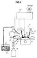
- Fig. 1 shows the system diagram of an engine (an internal combustion engine) of the first embodiment of the invention.
- An engine 10 is formed with a combustion chamber 14, which is defined by a cylinder head 11, a cylinder block 12, and a piston 13.
- Combustion chamber 14 is formed, so that intake air is introduced through an intake valve 15 via an intake port 16, serving as an intake-air passage, into the combustion chamber. Additionally, the combustion chamber is formed, so that exhaust gas is exhausted from the combustion chamber through an exhaust valve 17 into an exhaust port 18, serving as an exhaust-gas passage.
- a manifold section (an intake manifold) 19 is provided in a middle of the intake-air passage.
- a throttle valve 20 is further provided in the intake-air passage and located upstream of manifold section 19.
- the actuating shaft of throttle valve 20 is fixedly connected to an output shaft of a step motor 21.
- the output shaft of step motor 21 is rotated responsively to a command signal generated from an electronic engine control unit (ECU) 25, so as to operate throttle valve 20.
- ECU electronic engine control unit
- a fuel injection valve 31 is disposed in intake port 16.
- a liquid fuel F1 which is stored in a fuel tank 32, is supplied to fuel injection valve 31 by a fuel pump 33. Liquid fuel F1 is sprayed into intake port 16 by fuel injection valve 31, for example during an exhaust stroke, and then during the subsequent intake stroke a premixed mixture of the sprayed liquid fuel F1 and air is formed.
- liquid fuel F1, stored in fuel tank 32 is a gasoline fuel. It will be understood that the liquid fuel is not limited to such a gasoline fuel, but that other kinds of liquid fuel may be used.
- a gas injection valve 35 serving as a fuel gas supply device, is provided at a side part (a lateral part) of combustion chamber 14, namely, the intake-port side of the combustion chamber.
- a fuel gas F2 which is stored in a high-pressure gas canister 36, is supplied via a fuel-gas pump 37 into gas injection valve 35.
- Fuel gas F2, stored in gas canister 36 is a fuel gas whose burning velocity is greater than that of the premixed mixture formed in combustion chamber 14.
- hydrogen, acetylene, or ethylene is used as the fuel gas.
- hydrogen is an easily ignitable fuel gas, and thus it has the advantage of superior ignitability, even during the igniting action within the fuel spray.
- Hydrogen has the further advantage of faster burning velocity and enlarged lean-combustion limit (or enlarged lean misfire limit), as compared to the premixed mixture. Therefore, by the use of hydrogen, it is possible to sustain or keep up the flame even within the spray of fuel gas F2 without misfire.
- a mixture of fuel gas F2 mixed with oxygen functioning as an oxidizer, may be supplied to gas injection valve 35.
- a spark plug 38 serving as an ignition device for igniting the spray of fuel gas F2 sprayed from gas injection valve 35, is located on the top face of combustion chamber 14 in such a manner as to be slightly offset from the center of the top face toward the side of installation of gas injection valve 35. It will be understood that the ignition device is not limited to such a spark plug 38, but that other types of igniters, such as a glow lamp, a laser ignition device or the like, may be used.
- ECU 25 Signals from engine/vehicle sensors, such as a crank-angle sensor 41, a coolant temperature sensor 42, an accelerator-position sensor 43, and the like, are input into ECU 25.
- Electronic control for each of throttle valve 20, fuel injection valve 31, gas injection valve 35, and spark plug 38 is made based on the input information received by the ECU.
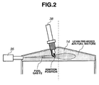
- Fig. 2 is the cross section showing the detailed form of combustion of the lean premixed mixture in the combustion chamber in the case of the first embodiment.
- Gas injection valve 35 is located at the intake-port side of combustion chamber 14, in such a manner as to horizontally inject fuel gas F2 toward the other side part of combustion chamber 14 opposite to the side of installation of gas injection valve 35.
- spark plug 38 is provided, so that the ignition position of the spark plug, namely a spark-plug gap, is located within the spray of fuel gas F2 sprayed from gas injection valve 35.
- the spark plug is laid out or configured, so that the spark-plug gap is located to be slightly offset from a midpoint of the nozzle of gas injection valve 35, and the endpoint of the fuel-spray travel of the sprayed fuel gas F2, toward the side of installation of gas injection valve 35.
- fuel gas F2 is injected from gas injection valve 35 into the lean premixed mixture of liquid fuel F1 and air, which mixture is preliminarily formed in combustion chamber 14. Then, a spray of the fuel gas F2 can be produced in the predetermined area of the combustion chamber, substantially extending from one end of the cylinder bore to the other end as viewed in the cylinder-bore direction defined by the centerline of the cylinder bore and including the igniter.
- Spark plug 38 is configured to ignite the spray of fuel gas F2, after the tip of the spray of the sprayed fuel gas F2 has passed through the ignition position of spark plug 38, namely the spark-plug gap, and after the middle stage of the fuel-injection time period for fuel gas F2 injected by gas injection valve 35.
- the flame, produced by spark-ignition tends to enlarge along fuel-spray flow of fuel gas F2.
- the turbulent flow occurring within the spray of fuel gas F2 tends to be strengthened.
- the flame rapidly develops or enlarges toward the tip of the spray of fuel gas F2.
- the jet flame produced by combustion of the fuel-spray flow of fuel gas F2 diffused in combustion chamber 14, acts to burn the lean premixed mixture, which mixture is preliminarily formed in combustion chamber 14, by way of flame propagation. Additionally, turbulent mixing promotes combustion of the lean premixed mixture.
- a burn time duration of fuel gas F2 in combustion chamber 14 can be controlled by varying the fuel injection timing of gas injection valve 35 (that is, the fuel-injection start timing and the fuel-injection termination timing), and/or the ignition timing of spark plug 38.
- a time duration of generation of heat of combustion for fuel gas F2 can be controlled by varying the quantity of fuel injected by gas injection valve 35. Therefore, the fuel injection quantity and fuel injection timing of gas injection valve 35, and the ignition timing of spark plug 38 are set, while fully taking into account various factors, that is, thermal efficiency, exhaust emissions, noise, vibrations and the like. These set values are pre-stored in memories of ECU 25.
- Fig. 3 is the diagram showing switching between combustion modes of the mixture in the combustion chamber in the case of the first embodiment.
- the engine during low-load and low-speed operation of engine 10, it is determined that the engine is operated in a lean combustion operating range. As discussed above, the lean premixed mixture is ignited and burned, while utilizing fuel gas F2. This realizes the enhanced thermal efficiency and the reduced exhaust emissions. Conversely, during high-load and high-speed operation of engine 10, it is determined that the engine is operated in a stoichiometric combustion operating range. Only the mixture of liquid fuel F1 and air is supplied into combustion chamber 14, and then the supplied mixture is directly spark-ignited for stoichiometric combustion. This realizes the increased power output.
- the spray of fuel gas F2 passes through the ignition position of the ignition device (spark plug 38) and diffuses into combustion chamber 14.
- the spray of fuel gas F2 produces a strong turbulent flow in combustion chamber 14. Therefore, the mixing action of the flame, produced by combustion of fuel gas F2, with the unburned lean premixed mixture can be promoted, and as a result the lean premixed mixture can be certainly burned.
- the flame produced by combustion of fuel gas F2
- fuel gas F2 is injected into combustion chamber 14, while evaporated.
- soot and smoke which are produced by the ignition device (spark plug 38) due to a lack of evaporation of liquid fuel, which is directly injected into combustion chamber 14.
- the ignition position of the ignition device is arranged in such a manner as to be slightly offset from a midpoint of the nozzle of the fuel gas supply device (gas injection valve 35) and the endpoint of the fuel-spray travel of the sprayed fuel gas F2, toward the side of installation of the fuel gas supply device (gas injection valve 35).
- the turbulent-flow strengthening action attained by the fuel-spray flow of fuel gas F2, can be effectively utilized even downstream of the ignition position.
- the ignition device (spark plug 38) is configured to ignite the spray of fuel gas F2, after the tip of the spray of the sprayed fuel gas F2 has passed through the ignition position of the ignition device (spark plug 38), and after the middle stage of the fuel-injection time period for fuel gas F2 injected by gas injection valve 35.
- An igniting action for the spray of fuel gas F2 is initiated, after an adequate turbulent-flow field has been produced in combustion chamber 14 by way of the spray of fuel gas F2, thereby promoting the flame diffusion along the spray of fuel gas F2.
- the fuel gas supply device (gas injection valve 35) is laid out at a side part (a lateral part) of combustion chamber 14, in such a manner as to inject fuel gas F2 toward the other side part of combustion chamber 14 opposite to the side of installation of the fuel gas supply device (gas injection valve 35). This ensures the ease of installation of the fuel gas supply device (gas injection valve 35), as compared to the layout of the fuel gas supply device (gas injection valve 35) on the center of the top face of combustion chamber 14.
- fuel gas F2 is a fuel gas (such as hydrogen, acetylene, ethylene, or the like) whose burning velocity is greater than that of the premixed mixture.
- the ignition device spark plug 38.
- fuel gas F2 may be a mixture containing an oxidizer, such as oxygen.
- an oxidizer such as oxygen.
- FIG. 4 shows the system diagram of an engine (an internal combustion engine) of the second embodiment of the invention. Only the points of the second embodiment, differing from the first embodiment explained with reference to Fig. 1 , are hereunder described.
- a first fuel injection valve 51 a and a second fuel injection valve 51 b both serving as the premixed mixture formation device, are provided in intake port 16.
- a hydrocarbon fuel F3 having a low self-ignitability is supplied to first fuel injection valve 51 a via a fuel separator 61 (described later) by a fuel pump 62.
- a hydrocarbon fuel F4 having a high self-ignitability is supplied to second fuel injection valve 51 b via a fuel reformer 63 (described later) by a fuel pump 64.
- Hydrocarbon fuel F3, having a low self-ignitability is a hydrocarbon fuel that contains a high percentage of aromatic hydrocarbons, isoparaffin, olefin, and so forth.
- Hydrocarbon fuel F4, having a high self-ignitability is a hydrocarbon fuel that contains a high percentage of normal paraffin.
- Gas injection valve 35 serving as the fuel gas supply device, is located at the center of the top face of combustion chamber 14, for injecting fuel gas F5 conically into combustion chamber 14. Fuel gas F5 is supplied to gas injection valve 35 via fuel reformer 63 (described later) by fuel pump 65.
- Spark plug 38 serving as the ignition device for igniting the spray of fuel gas F5 sprayed from gas injection valve 35, is located on the top face of combustion chamber 14 in such a manner as to be slightly offset from a midpoint of the nozzle of gas injection valve 35 located at the center of the top face of combustion chamber 14 and a side part (a lateral part, that is, the endpoint of the fuel-spray travel of the sprayed fuel gas F5) of combustion chamber 14, toward the side of installation of gas injection valve 35.
- the hydrocarbon fuel supplied from the outside, is fed from fuel tank 32, which stores the fuel, via a low-pressure fuel pump 66 to fuel separator 61.
- fuel separator 61 normal paraffin contained in the fuel is separated by a separator filter (or a separator membrane) installed in fuel separator 61.
- the separated normal paraffin is fed via a fuel pump (not shown) to fuel reformer 63.
- Fuel reformer 63 is configured to be able to receive exhaust heat from engine 10.
- part of the normal paraffin separated by fuel separator 61 is converted into hydrogen (fuel gas F5) and hydrocarbon fuel F3 having a low self-ignitability, by way of dehydrogenation (reforming reaction) utilizing a catalyst (such as platinum system catalyst).
- Hydrogen (fuel gas F5), produced by fuel reformer 63, is supplied to gas injection valve 35 by fuel gas pump 65.
- Hydrocarbon fuel F3 having a low self-ignitability and produced by fuel reformer 63, is returned via the fuel pump (not shown) to fuel separator 61. Thereafter, as the hydrocarbon fuel F3 having a low self-ignitability, the returned hydrocarbon fuel is supplied via fuel pump 62 to the first fuel injection valve 51 a together with the residual fuel obtained after separation of normal paraffin by the separator membrane installed in fuel separator 61.
- the hydrocarbon fuel F4 having a high self-ignitability normal paraffin, which is not subjected to the reforming reaction within fuel reformer 63, is supplied via fuel pump 64 to the second fuel injection valve 51 b.
- part of normal paraffin, separated by fuel separator 61 may be converted to produce hydrogen (fuel gas F5) by way of partial oxidation (reforming reaction) utilizing a rhodium system catalyst, within fuel reformer 63.
- partial oxidation reforming reaction
- the chemical reaction is represented by the following reaction formula.
- Hydrogen (fuel gas F5), produced by fuel reformer 63, is supplied via fuel gas pump 65 to gas injection valve 35.
- hydrocarbon fuel F4 having a high self-ignitability, part of normal paraffin, which is not subjected to the reforming reaction within fuel reformer 63, is supplied via fuel pump 64 to the second fuel injection valve 51 b.
- Fig. 5 is the cross section showing the detailed form of combustion of the lean premixed mixture in the combustion chamber in the case of the second embodiment.
- Gas injection valve 35 is located at the center of the top face of combustion chamber 14, for injecting fuel gas F5 conically (in the form of a hollow cone) into combustion chamber 14.
- spark plug 38 is configured so that its ignition position (a spark-plug gap) is located within the spray of fuel gas F5, injected by gas injection valve 35, in such a manner to be slightly offset from a midpoint of the nozzle of gas injection valve 35 and the endpoint of the fuel-spray travel of the sprayed fuel gas F5 (a side part of combustion chamber 14), toward the side of installation of gas injection valve 35.
- Fuel gas F5 is injected from gas injection valve 35 into a lean premixed mixture, preliminarily formed in combustion chamber 14 by mixing hydrocarbon fuel F3 having a low self-ignitability and hydrocarbon fuel F4 having a high self-ignitability with air, at the last stage of a compression stroke (near a top dead center position on the compression stroke).
- a spray of the fuel gas is formed or produced in a predetermined area of the combustion chamber, substantially extending from one end of a cylinder bore to the other end as viewed in a cylinder-bore direction defined by a centerline of the cylinder bore and including an igniter.
- Spark plug 38 is configured to ignite the spray of fuel gas F5, after the tip of the spray of the sprayed fuel gas F5 has passed through the ignition position of spark plug 38, namely the spark-plug gap, and after the middle stage of the fuel-injection time period for fuel gas F5 injected by gas injection valve 35.
- the flame, produced by spark-ignition tends to enlarge along fuel-spray flow of fuel gas F5.
- the turbulent flow, occurring within the spray of fuel gas F5 tends to be strengthened.
- the flame rapidly develops or enlarges toward the tip of the spray of fuel gas F5.
- the jet flame produced by combustion of the fuel-spray flow of fuel gas F5 diffused in combustion chamber 14, acts to burn the lean premixed mixture, which is preliminarily formed in combustion chamber 14, by way of flame propagation. Additionally, turbulent mixing promotes combustion of the lean premixed mixture. Furthermore, owing to the presence of hydrocarbon fuel F4 having a high self-ignitability, locally self-ignited combustion in combustion chamber 14 can be induced. Thus, it is possible to certainly satisfactorily burn the lean premixed mixture within the combustion chamber 14 as widely as possible.
- the form of combustion of the lean premixed mixture seen in Fig. 6 may be used.
- Gas injection valve 35 shown in Fig. 6 has a single nozzle, which is configured to inject fuel gas F5 toward the center section of the piston crown of a reciprocating piston 13.
- Piston 13 has a recessed cavity 13a formed in the center section of the piston crown.
- the spray of fuel gas F5, injected from gas injection valve 35, impinges with cavity 13a, and then diffuses along the bottom face of cavity 13a. Thereafter, the fuel spray travels up along the peripheral wall surface of cavity 13a and thus spreads out over combustion chamber 14.
- spark plug 38 is configured so that its ignition position (a spark-plug gap) is located within the spray of fuel gas F5, injected by gas injection valve 35, in such a manner to be slightly offset from a midpoint of the nozzle of gas injection valve 35 and the endpoint of the fuel-spray travel of the sprayed fuel gas F5 (i.e., the bottom face of cavity 13a at the top dead center position on the compression stroke), toward the side of installation of gas injection valve 35.
- Fig. 7A is the characteristic diagram showing the relationship between the engine load and the excess air factor in the lean combustion operating range.
- a fuel supply control device which is incorporated in ECU 25, is configured to control throttle valve 20, the first fuel injection valve 51 a, the second fuel injection valve 51 b, and gas injection valve 35, in a manner so as to increase the excess air factor, as the engine load decreases.
- the premixed mixture formed in combustion chamber 14 is leaned out, as the engine load decreases.
- Fig. 7B is the characteristic diagram showing the relationship between the engine load and the fuel supply ratio, in the lean combustion operating range.
- a premixed mixture fuel supply control device which is incorporated in ECU 25, is configured to control the first fuel injection valve 51 a and the second fuel injection valve 51 b, in a manner so as to decrease a fuel-supply ratio of hydrocarbon fuel F3 having a low self-ignitability and to increase a fuel-supply ratio of hydrocarbon fuel F4 having a high self-ignitability, as the engine load decreases.
- the self-ignitability of the premixed mixture formed in combustion chamber 14 increases, as the engine load decreases.
- the fuel supply control device incorporated in ECU 25 is configured to control gas injection valve 35 in a manner so as to increase a fuel-supply ratio of fuel gas F5, as the engine load decreases. As a result, it is possible to strengthen the jet flame produced by combustion of the spray of fuel gas F5, thus enhancing the effect to promote combustion of the premixed mixture, and ensuring complete combustion of the premixed mixture.
- Fig. 8 is the flow chart showing the fuel supply control flow of the second embodiment.
- step S102 signals generated from various sensors, that is, crank-angle sensor 41, coolant temperature sensor 42, accelerator-position sensor 43, and the like, are read by ECU 25.
- step S103 engine operating states, such as engine load and engine speed, are determined based on input information from the sensors.
- step S104 a combustion mode for the mixture in combustion chamber 14 is determined, utilizing the characteristic diagram of Fig. 3 .
- low-load and low-speed operation it is determined that the engine is operated in a lean combustion operating range.
- high-load and high-speed operation it is determined that the engine is operated in a stoichiometric combustion operating range.
- step S104 determines that the engine is operated in the lean combustion operating mode
- the routine proceeds to step S105, at which time the fuel injection quantity and fuel injection timing of fuel injection valve 51 a, provided to inject hydrocarbon fuel F3 having a low self-ignitability, are retrieved and determined based on a "lean-combustion fuel-gas F3 injection table" pre-stored in ECU 25.
- step S106 the routine proceeds to step S106, at which time the fuel injection quantity and fuel injection timing of fuel injection valve 51 b, provided to inject hydrocarbon fuel F4 having a high self-ignitability, are retrieved and determined based on a "lean-combustion fuel-gas F4 injection table" pre-stored in ECU 25.
- step S107 the routine proceeds to step S107, at which time the fuel injection quantity and fuel injection timing of gas injection valve 35, provided to inject fuel gas F5, are retrieved and determined based on a "lean-combustion fuel-gas F5 injection table" pre-stored in ECU 25. Then, the routine proceeds to step S110.
- step S110 the fuel-supply quantity and fuel-supply timing of each of the fuels F3-F5 to be supplied to engine 10 are controlled based on the decision results of steps S105, S106, and S107, by the fuel supply control device and the premixed mixture fuel supply control device, both incorporated in ECU 25.
- step S104 determines that the engine is operated in the stoichiometric combustion operating mode
- the routine proceeds to step S115, at which time the fuel injection quantity and fuel injection timing of fuel injection valve 51 a, provided to inject hydrocarbon fuel F3 having a low self-ignitability, are retrieved and determined based on a "stoichiometric-combustion fuel-gas F3 injection table" pre-stored in ECU 25. Thereafter, the routine proceeds to step S110.
- step S110 the fuel-supply quantity and fuel-supply timing of the fuel (only the hydrocarbon fuel F3 having a low self-ignitability) to be supplied to engine 10 are controlled based on the decision result of step S115, by the fuel supply control device and the premixed mixture fuel supply control device, both incorporated in ECU 25.
- the fuel gas supply device (gas injection valve 35) is located at the center of the top face of combustion chamber 14, for injecting fuel gas F5 conically into combustion chamber 14.
- the spray of fuel gas F5 can be diffused impartially within combustion chamber 14, and thus it is possible to suppress the localized occurrence of unburned hydrocarbon in combustion chamber 14.
- the fuel gas supply device has a single nozzle and is located at the center of the top face of combustion chamber 14, for injecting fuel gas F5 toward the cavity 13a of the crown of piston 13.
- fuel gas F5 is a fuel gas, produced when fuel-reforming a hydrocarbon fuel, supplied externally, by way of a reforming reaction.
- fuel gas F5 is a fuel gas, produced when fuel-reforming a hydrocarbon fuel, supplied externally, by way of a reforming reaction.
- the reforming reaction by which fuel gas F5 is produced utilizes exhaust heat from the internal combustion engine 10.
- exhaust heat from the internal combustion engine 10.
- the reforming reaction by which fuel gas F5 is produced includes dehydrogenation, and thus it is possible to produce high-purity hydrogen gas, rather than partial oxidation.
- This enables the reduced injection quantity of fuel injected from the gas fuel supply device (gas injection valve 35), as compared to partial oxidation, and thus it is possible to down-size the fuel-supply system.
- the reforming reaction by which fuel gas F5 is produced may include partial oxidation (an exothermic reaction).
- an exothermic reaction an exothermic reaction
- hydrocarbon fuel F3 having a low self-ignitability is supplied to the premixed mixture formation device.
- it is possible to suppress the occurrence of knocking due to rapid combustion.
- hydrocarbon fuel F4 having a high self-ignitability is supplied to the premixed mixture formation device.
- the premixed mixture is very lean
- ECU 25 employs the fuel supply control device configured to execute fuel-supply control, in such a manner as to lean out the premixed mixture formed in combustion chamber 14 by the premixed mixture formation device and to increase the fuel-supply quantity of fuel gas F5 to be supplied from the fuel gas supply device (gas injection valve 35) into combustion chamber 14, as the load of the internal combustion engine (engine 10) decreases.
- the fuel supply control device gas injection valve 35
- the fuel-supply quantity of fuel gas F5 is controlled to reduce.
- ECU 25 employs the premixed mixture fuel supply control device configured to execute fuel-supply ratio control, in such a manner as to increase a fuel-supply ratio of hydrocarbon fuel F4 having a high self-ignitability and to decrease a fuel-supply ratio of hydrocarbon fuel F3 having a low self-ignitability, as the load of the internal combustion engine (engine 10) decreases.
- the premixed mixture fuel supply control device configured to execute fuel-supply ratio control, in such a manner as to increase a fuel-supply ratio of hydrocarbon fuel F4 having a high self-ignitability and to decrease a fuel-supply ratio of hydrocarbon fuel F3 having a low self-ignitability, as the load of the internal combustion engine (engine 10) decreases.
- hydrocarbon fuel F3 having a low self-ignitability is a fuel produced when fuel-reforming a hydrocarbon fuel, supplied externally, by way of a reforming reaction.
- the reforming reaction by which hydrocarbon fuel F3 having a low self-ignitability is produced includes cyclodehydrogenation, and thus it is possible to produce a low self-ignitability fuel that contains a high percentage of aromatic hydrocarbons, and simultaneously to produce hydrogen gas (fuel gas F5).
- hydrocarbon fuel F4 having a high self-ignitability is a fuel obtained when separating a hydrocarbon fuel, supplied externally, by means of a separator membrane.
- an additional fuel tank that stores hydrocarbon fuel F4. it is possible to down-size the fuel-supply system in comparison with the use of the additional fuel tank.
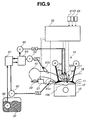
- FIG. 9 shows the system diagram of an engine (an internal combustion engine) of the third embodiment of the invention. Only the points of the third embodiment, differing from the second embodiment explained with reference to Fig. 4 , are hereunder described.
- a first gas injection valve 55a and a second gas injection valve 55b serving as the fuel gas supply device, are located at the center of the top face of combustion chamber 14.
- the first gas injection valve 55a has a single nozzle, for injecting fuel gas F5 toward the center of the piston crown of a reciprocating piston 13.
- Piston 13 has a recessed cavity 13b (a small bowl) formed in the center section of the piston crown.
- the second gas injection valve 55b is configured to inject fuel gas F5 radially into combustion chamber 14.
- fuel gas F5 is supplied to each of the first and second gas injection valves 55a-55b via fuel reformer 63 by fuel pump 65.
- Fuel-supply control for the first gas injection valve 55a and fuel-supply control for the second injection valve 55b can be made independently of each other by the fuel supply control device, incorporated in ECU 25.
- Fig. 10 is the cross section showing the detailed form of combustion of the lean premixed mixture in the combustion chamber in the case of the third embodiment.
- Fuel gas F5 is injected from the first gas injection valve 55a into a lean premixed mixture, preliminarily formed in combustion chamber 14 by mixing hydrocarbon fuel F3 having a low self-ignitability and hydrocarbon fuel F4 having a high self-ignitability with air, in such a manner as to direct the fuel gas toward the recessed cavity 13b (small bowl) formed in the center section of the crown of piston 13, at the last stage of a compression stroke (near a top dead center position on the compression stroke).
- the concentrated mixture obtained by mixing the lean premixed mixture with the spray of fuel gas F5 is formed in the specified space of combustion chamber 14 between the first gas injection valve 55a and cavity 13b (small bowl).
- fuel gas F5 is injected from the second gas injection valve 55b radially into combustion chamber 15.
- a spray of fuel gas F5, injected radially is formed in such a manner as to penetrate the concentrated air-fuel mixture.
- spark plug 38 is configured so that its ignition position (a spark-plug gap) is located within the concentrated mixture, in such a manner to be slightly offset from a midpoint of the nozzle of gas injection valve 55a and the endpoint of the fuel-spray travel of the concentrated mixture (i.e., the bottom face of cavity 13b (small bowl) at the top dead center position on the compression stroke), toward the side of installation of gas injection valve 55a, for spark-ignition and burning of the concentrated mixture.
- the flame produced by spark-ignition and burning of the concentrated mixture, tends to enlarge toward the radial spray of the fuel gas F5 injected radially.
- the jet flame of the radial spray of fuel gas F5 is produced within the combustion chamber 14 as widely as possible.
- Fig. 11 is the characteristic diagram used in setting of a compression ratio to be varied relative to engine load in the case of the third embodiment.
- the engine of the third embodiment employs a variable compression ratio mechanism (not shown), which is configured to variably adjust a compression ratio of engine 10. Also provided is a compression ratio control device (not shown) incorporated in ECU 25, for controlling the compression ratio based on engine load, via the variable compression ratio mechanism.
- the compression ratio control device is configured to execute compression-ratio control based on a set value of the compression ratio retrieved from the engine-load, versus the compression ratio look-up table shown in Fig. 11 .
- the settings of compression ratio relative to engine load are preprogrammed to increase the compression ratio so as to enhance a thermal efficiency during low load operation of engine 10, and to decrease the compression ratio so as to avoid abnormal combustion such as knocking during high load operation.
- Fig. 12 is the flow chart showing the fuel supply control flow of the third embodiment. Only the points of the third embodiment, differing from the second embodiment explained with reference to Fig. 8 , are hereunder described.
- Step S107 of Fig. 12 differs from step S107 of Fig. 8 , in that the fuel injection quantity and fuel injection timing of each of the first and second gas injection valves 55a-55b, both provided to inject fuel gas F5, are determined based on a "lean-combustion fuel-gas F5 injection table" pre-stored in ECU 25.
- the compression ratio table look-up and compression ratio control are made via respective steps S208-S209, before execution of fuel-supply control of step S110.
- step S208 the look-up operation of the compression ratio table (see Fig. 11 ) is made based on the engine operating states determined through step S103. Thereafter, the routine proceeds to step S209.
- step S209 the compression ratio is controlled by the compression ratio control device. Thereafter, the routine proceeds to step S110 at which fuel-supply control is executed in the same manner as Fig. 8 .
- the fuel gas supply device is constructed by the first and second gas injection valves 55a-55b, both located at the center of the top face of combustion chamber 14.
- the concentrated mixture is formed by mixing the premixed mixture with a spray of fuel gas F5 by way of injection of fuel gas F5 from the first gas injection valve toward cavity 13b (small bowl) formed in the piston crown. Thereafter, a radial spray of fuel gas F5 is produced by way of radial injection of fuel gas F5 from the second gas injection valve into combustion chamber 14.
- the concentrated mixture is spark-ignited and burned by the ignition device (spark plug 38), and then the radial spray of fuel gas F5 can be ignited by way of the flame, produced by spark-ignition and burning of the concentrated mixture.
- the spray of fuel gas F5 can be diffused impartially within combustion chamber 14, and thus it is possible to suppress the localized occurrence of unburned hydrocarbon in combustion chamber 14.
Applications Claiming Priority (1)
| Application Number | Priority Date | Filing Date | Title |
|---|---|---|---|
| JP2007111085A JP2008267267A (ja) | 2007-04-20 | 2007-04-20 | 内燃機関 |
Publications (1)
| Publication Number | Publication Date |
|---|---|
| EP1983169A1 true EP1983169A1 (de) | 2008-10-22 |
Family
ID=39650957
Family Applications (1)
| Application Number | Title | Priority Date | Filing Date |
|---|---|---|---|
| EP08154717A Withdrawn EP1983169A1 (de) | 2007-04-20 | 2008-04-17 | Verbrennungsmotor und Verbrennungsverfahren dafür |
Country Status (4)
| Country | Link |
|---|---|
| US (1) | US20080257304A1 (de) |
| EP (1) | EP1983169A1 (de) |
| JP (1) | JP2008267267A (de) |
| CN (1) | CN101289964A (de) |
Cited By (6)
| Publication number | Priority date | Publication date | Assignee | Title |
|---|---|---|---|---|
| WO2010063613A1 (de) * | 2008-12-01 | 2010-06-10 | Robert Bosch Gmbh | Brennkraftmaschine |
| EP2246546A3 (de) * | 2009-04-21 | 2010-12-08 | Honda Motor Co., Ltd. | Steuervorrichtung eines Verbrennungsmotors |
| CN101963113A (zh) * | 2009-07-23 | 2011-02-02 | 福特环球技术公司 | 发动机及其控制方法 |
| WO2013173069A1 (en) * | 2012-05-17 | 2013-11-21 | General Electric Company | Method and system for engine control |
| WO2016016229A3 (de) * | 2014-07-30 | 2016-05-06 | Fev Gmbh | Brennkammergestaltung eines vcr-motors |
| EP2812546A4 (de) * | 2012-02-07 | 2016-06-08 | Westport Power Inc | Vorrichtung und verfahren zum zünden eines gasförmigen kraftstoffes in einer brennkraftmaschine mit direkteinspritzung |
Families Citing this family (27)
| Publication number | Priority date | Publication date | Assignee | Title |
|---|---|---|---|---|
| DE102008003842A1 (de) * | 2008-01-10 | 2009-07-16 | Robert Bosch Gmbh | Verfahren zum Verbrennen von Kraftstoff |
| CN101749136A (zh) * | 2008-12-19 | 2010-06-23 | 天津内燃机研究所 | 电控燃气缸内直喷发动机 |
| US8371118B2 (en) * | 2009-07-07 | 2013-02-12 | Ford Global Technologies, Llc | Oxidant injection to reduce turbo lag |
| US8347624B2 (en) * | 2009-07-07 | 2013-01-08 | Ford Global Technologies, Llc | Oxidant injection during cold engine start |
| CN101907025A (zh) * | 2010-06-28 | 2010-12-08 | 大连理工大学 | 内燃机多燃料燃烧系统 |
| US8590510B2 (en) | 2010-08-24 | 2013-11-26 | Ford Global Technologies, Llc | Fuel system for a multi-fuel engine |
| US8776764B2 (en) | 2011-01-04 | 2014-07-15 | Ford Global Technologies, Llc | Fuel system for a multi-fuel engine |
| CN102619628A (zh) * | 2011-01-30 | 2012-08-01 | 北汽福田汽车股份有限公司 | 缸内直喷汽油机及缸内直喷汽油机掺烧方法 |
| US8851045B2 (en) * | 2011-03-31 | 2014-10-07 | Wisconsin Alumni Research Foundation | Engine combustion control at low loads via fuel reactivity stratification |
| JP5723201B2 (ja) * | 2011-04-18 | 2015-05-27 | 川崎重工業株式会社 | 燃料噴射制御装置 |
| WO2013021434A1 (ja) * | 2011-08-05 | 2013-02-14 | トヨタ自動車株式会社 | 内燃機関の燃料供給装置 |
| US9051887B2 (en) * | 2012-07-27 | 2015-06-09 | Caterpillar Inc. | System and method for adjusting fuel reactivity |
| JP6119199B2 (ja) * | 2012-11-08 | 2017-04-26 | 株式会社デンソー | ガスエンジンの燃料供給装置 |
| US9151222B2 (en) * | 2012-12-12 | 2015-10-06 | Caterpillar Inc. | Six-stroke combustion cycle engine and process |
| US9587578B2 (en) | 2013-12-06 | 2017-03-07 | Ford Global Technologies, Llc | Adaptive learning of duty cycle for a high pressure fuel pump |
| EP2992195B1 (de) * | 2014-01-21 | 2016-09-21 | KREUTER, Peter | Hubkolbenbrennkraftmaschine sowie verfahren zum betreiben einer hubkolbenbrennkraftmaschine |
| US9243598B2 (en) | 2014-02-25 | 2016-01-26 | Ford Global Technologies, Llc | Methods for determining fuel bulk modulus in a high-pressure pump |
| US9458806B2 (en) | 2014-02-25 | 2016-10-04 | Ford Global Technologies, Llc | Methods for correcting spill valve timing error of a high pressure pump |
| US9874185B2 (en) | 2014-05-21 | 2018-01-23 | Ford Global Technologies, Llc | Direct injection pump control for low fuel pumping volumes |
| CN104500248A (zh) * | 2014-12-19 | 2015-04-08 | 华北水利水电大学 | 天然气发动机燃料供给装置多次喷射控制方法 |
| US10001090B1 (en) * | 2015-03-26 | 2018-06-19 | The Research Foundation For The State University Of New York | Single-fuel reactivity controlled compression ignition combustion enabled by onboard fuel reformation |
| JP2017207011A (ja) * | 2016-05-19 | 2017-11-24 | 日立オートモティブシステムズ株式会社 | 内燃機関制御装置 |
| JP6679435B2 (ja) * | 2016-07-14 | 2020-04-15 | ヤンマー株式会社 | エンジン |
| CN108571392B (zh) * | 2017-03-10 | 2020-10-09 | 联合汽车电子有限公司 | 用于点燃式发动机的稀薄燃烧系统及方法 |
| GB201717437D0 (en) * | 2017-10-24 | 2017-12-06 | Rolls Royce Plc | Apparatus and methods for controlling reciprocating internal combustion engines |
| GB201717438D0 (en) * | 2017-10-24 | 2017-12-06 | Rolls Royce Plc | Apparatus amd methods for controlling reciprocating internal combustion engines |
| CN112709648A (zh) * | 2019-10-25 | 2021-04-27 | 湖南罗佑发动机部件有限公司 | 一种发动机燃烧控制系统及方法 |
Citations (6)
| Publication number | Priority date | Publication date | Assignee | Title |
|---|---|---|---|---|
| GB1389383A (en) * | 1972-06-21 | 1975-04-03 | Texaco Development Corp | Internal combustion engine having fuel injection into a premixed charge |
| US4546740A (en) * | 1983-04-11 | 1985-10-15 | University Of Victoria | Ignition source for internal combustion engine |
| US4864989A (en) * | 1988-06-30 | 1989-09-12 | Tice Technologies Corp. | Pre-combustion chamber spark plug and method of igniting lean fuel |
| US20060278195A1 (en) * | 2005-06-10 | 2006-12-14 | Nissan Motor Co., Ltd. | Internal combustion engine with auxiliary combustion chamber |
| JP2007111085A (ja) | 2005-10-18 | 2007-05-10 | Matsushita Electric Ind Co Ltd | 食器洗い乾燥機および厨房装置 |
| EP1798393A2 (de) * | 2005-12-15 | 2007-06-20 | Nissan Motor Co., Ltd. | Brennkraftmaschine |
Family Cites Families (3)
| Publication number | Priority date | Publication date | Assignee | Title |
|---|---|---|---|---|
| JP2002317669A (ja) * | 2001-04-19 | 2002-10-31 | Mitsubishi Electric Corp | 内燃機関の燃料噴射制御装置 |
| JP2004176710A (ja) * | 2002-10-01 | 2004-06-24 | Toyota Motor Corp | 動力出力装置及びハイブリッド型の動力出力装置、それらの制御方法並びにハイブリッド車両 |
| JP4158583B2 (ja) * | 2003-04-11 | 2008-10-01 | トヨタ自動車株式会社 | 内燃機関の始動装置 |
-
2007
- 2007-04-20 JP JP2007111085A patent/JP2008267267A/ja active Pending
-
2008
- 2008-03-28 US US12/057,572 patent/US20080257304A1/en not_active Abandoned
- 2008-04-17 EP EP08154717A patent/EP1983169A1/de not_active Withdrawn
- 2008-04-21 CN CNA2008100912134A patent/CN101289964A/zh active Pending
Patent Citations (6)
| Publication number | Priority date | Publication date | Assignee | Title |
|---|---|---|---|---|
| GB1389383A (en) * | 1972-06-21 | 1975-04-03 | Texaco Development Corp | Internal combustion engine having fuel injection into a premixed charge |
| US4546740A (en) * | 1983-04-11 | 1985-10-15 | University Of Victoria | Ignition source for internal combustion engine |
| US4864989A (en) * | 1988-06-30 | 1989-09-12 | Tice Technologies Corp. | Pre-combustion chamber spark plug and method of igniting lean fuel |
| US20060278195A1 (en) * | 2005-06-10 | 2006-12-14 | Nissan Motor Co., Ltd. | Internal combustion engine with auxiliary combustion chamber |
| JP2007111085A (ja) | 2005-10-18 | 2007-05-10 | Matsushita Electric Ind Co Ltd | 食器洗い乾燥機および厨房装置 |
| EP1798393A2 (de) * | 2005-12-15 | 2007-06-20 | Nissan Motor Co., Ltd. | Brennkraftmaschine |
Cited By (9)
| Publication number | Priority date | Publication date | Assignee | Title |
|---|---|---|---|---|
| WO2010063613A1 (de) * | 2008-12-01 | 2010-06-10 | Robert Bosch Gmbh | Brennkraftmaschine |
| EP2246546A3 (de) * | 2009-04-21 | 2010-12-08 | Honda Motor Co., Ltd. | Steuervorrichtung eines Verbrennungsmotors |
| US8396644B2 (en) | 2009-04-21 | 2013-03-12 | Honda Motor Co., Ltd. | Control device for internal combustion engine |
| CN101963113A (zh) * | 2009-07-23 | 2011-02-02 | 福特环球技术公司 | 发动机及其控制方法 |
| CN101963113B (zh) * | 2009-07-23 | 2015-05-13 | 福特环球技术公司 | 发动机及其控制方法 |
| EP2812546A4 (de) * | 2012-02-07 | 2016-06-08 | Westport Power Inc | Vorrichtung und verfahren zum zünden eines gasförmigen kraftstoffes in einer brennkraftmaschine mit direkteinspritzung |
| US9790868B2 (en) | 2012-02-07 | 2017-10-17 | Westport Power Inc. | Apparatus and method for igniting a gaseous fuel in a direct injection internal combustion engine |
| WO2013173069A1 (en) * | 2012-05-17 | 2013-11-21 | General Electric Company | Method and system for engine control |
| WO2016016229A3 (de) * | 2014-07-30 | 2016-05-06 | Fev Gmbh | Brennkammergestaltung eines vcr-motors |
Also Published As
| Publication number | Publication date |
|---|---|
| CN101289964A (zh) | 2008-10-22 |
| JP2008267267A (ja) | 2008-11-06 |
| US20080257304A1 (en) | 2008-10-23 |
Similar Documents
| Publication | Publication Date | Title |
|---|---|---|
| EP1983169A1 (de) | Verbrennungsmotor und Verbrennungsverfahren dafür | |
| JP3920526B2 (ja) | 火花点火式成層燃焼内燃機関 | |
| JP3975702B2 (ja) | 自己着火式エンジンの制御装置 | |
| KR101025142B1 (ko) | 가스 연료 내연기관 및 그 제어 방법 | |
| JP6225938B2 (ja) | 内燃機関の制御装置 | |
| RU2541346C2 (ru) | Способ эксплуатации двигателя внутреннего сгорания | |
| JP4126971B2 (ja) | 混合気を圧縮自着火させて運転する内燃機関、および内燃機関の制御方法 | |
| JP6249084B1 (ja) | 予混合圧縮着火式エンジン | |
| JP2002070558A (ja) | 圧縮自己着火式ガソリン内燃機関 | |
| JP7204982B2 (ja) | 水素を燃料とする内燃機関のマルチモード運転 | |
| JP2007198275A (ja) | ガス燃料内燃機関 | |
| JP2003090239A (ja) | 筒内直接噴射式内燃機関 | |
| JP3812292B2 (ja) | 内燃機関 | |
| JP2010196517A (ja) | 内燃機関の制御装置 | |
| JP3952710B2 (ja) | 圧縮自己着火式内燃機関 | |
| JP6471041B2 (ja) | 火花点火機関の噴射制御装置 | |
| JP2008184970A (ja) | ガソリンエンジンの制御装置 | |
| JP6252662B1 (ja) | 予混合圧縮着火式エンジン | |
| JP2006052686A (ja) | 内燃機関の制御装置 | |
| JP2006144750A (ja) | 圧縮着火内燃機関 | |
| WO2012114482A1 (ja) | 内燃機関の制御システム | |
| JP2001193465A (ja) | ディーゼルエンジン | |
| JP4967691B2 (ja) | ガソリンエンジンの制御装置 | |
| JPS62135611A (ja) | スパークアシストデイーゼル機関の燃焼室 | |
| JP6477848B1 (ja) | 予混合圧縮着火式エンジン |
Legal Events
| Date | Code | Title | Description |
|---|---|---|---|
| PUAI | Public reference made under article 153(3) epc to a published international application that has entered the european phase |
Free format text: ORIGINAL CODE: 0009012 |
|
| AK | Designated contracting states |
Kind code of ref document: A1 Designated state(s): AT BE BG CH CY CZ DE DK EE ES FI FR GB GR HR HU IE IS IT LI LT LU LV MC MT NL NO PL PT RO SE SI SK TR |
|
| AX | Request for extension of the european patent |
Extension state: AL BA MK RS |
|
| 17P | Request for examination filed |
Effective date: 20090422 |
|
| 17Q | First examination report despatched |
Effective date: 20090526 |
|
| AKX | Designation fees paid |
Designated state(s): DE FR GB |
|
| STAA | Information on the status of an ep patent application or granted ep patent |
Free format text: STATUS: THE APPLICATION IS DEEMED TO BE WITHDRAWN |
|
| 18D | Application deemed to be withdrawn |
Effective date: 20100727 |