EP1983161A1 - Sicherungsvorrichtung zur Sicherung eines quer gegenüber einer Horizontalebene aufgestellten Rotors einer Strömungsmaschine gegen Umkippen sowie Montagevorrichtung - Google Patents
Sicherungsvorrichtung zur Sicherung eines quer gegenüber einer Horizontalebene aufgestellten Rotors einer Strömungsmaschine gegen Umkippen sowie Montagevorrichtung Download PDFInfo
- Publication number
- EP1983161A1 EP1983161A1 EP20070007681 EP07007681A EP1983161A1 EP 1983161 A1 EP1983161 A1 EP 1983161A1 EP 20070007681 EP20070007681 EP 20070007681 EP 07007681 A EP07007681 A EP 07007681A EP 1983161 A1 EP1983161 A1 EP 1983161A1
- Authority
- EP
- European Patent Office
- Prior art keywords
- rotor
- securing device
- horizontal plane
- foundation
- support surface
- Prior art date
- Legal status (The legal status is an assumption and is not a legal conclusion. Google has not performed a legal analysis and makes no representation as to the accuracy of the status listed.)
- Withdrawn
Links
Images

Classifications
-
- F—MECHANICAL ENGINEERING; LIGHTING; HEATING; WEAPONS; BLASTING
- F04—POSITIVE - DISPLACEMENT MACHINES FOR LIQUIDS; PUMPS FOR LIQUIDS OR ELASTIC FLUIDS
- F04D—NON-POSITIVE-DISPLACEMENT PUMPS
- F04D29/00—Details, component parts, or accessories
- F04D29/60—Mounting; Assembling; Disassembling
- F04D29/64—Mounting; Assembling; Disassembling of axial pumps
- F04D29/644—Mounting; Assembling; Disassembling of axial pumps especially adapted for elastic fluid pumps
-
- F—MECHANICAL ENGINEERING; LIGHTING; HEATING; WEAPONS; BLASTING
- F01—MACHINES OR ENGINES IN GENERAL; ENGINE PLANTS IN GENERAL; STEAM ENGINES
- F01D—NON-POSITIVE DISPLACEMENT MACHINES OR ENGINES, e.g. STEAM TURBINES
- F01D25/00—Component parts, details, or accessories, not provided for in, or of interest apart from, other groups
- F01D25/28—Supporting or mounting arrangements, e.g. for turbine casing
-
- F—MECHANICAL ENGINEERING; LIGHTING; HEATING; WEAPONS; BLASTING
- F04—POSITIVE - DISPLACEMENT MACHINES FOR LIQUIDS; PUMPS FOR LIQUIDS OR ELASTIC FLUIDS
- F04D—NON-POSITIVE-DISPLACEMENT PUMPS
- F04D29/00—Details, component parts, or accessories
- F04D29/26—Rotors specially for elastic fluids
- F04D29/28—Rotors specially for elastic fluids for centrifugal or helico-centrifugal pumps for radial-flow or helico-centrifugal pumps
- F04D29/284—Rotors specially for elastic fluids for centrifugal or helico-centrifugal pumps for radial-flow or helico-centrifugal pumps for compressors
-
- F—MECHANICAL ENGINEERING; LIGHTING; HEATING; WEAPONS; BLASTING
- F05—INDEXING SCHEMES RELATING TO ENGINES OR PUMPS IN VARIOUS SUBCLASSES OF CLASSES F01-F04
- F05D—INDEXING SCHEME FOR ASPECTS RELATING TO NON-POSITIVE-DISPLACEMENT MACHINES OR ENGINES, GAS-TURBINES OR JET-PROPULSION PLANTS
- F05D2230/00—Manufacture
- F05D2230/60—Assembly methods
-
- F—MECHANICAL ENGINEERING; LIGHTING; HEATING; WEAPONS; BLASTING
- F05—INDEXING SCHEMES RELATING TO ENGINES OR PUMPS IN VARIOUS SUBCLASSES OF CLASSES F01-F04
- F05D—INDEXING SCHEME FOR ASPECTS RELATING TO NON-POSITIVE-DISPLACEMENT MACHINES OR ENGINES, GAS-TURBINES OR JET-PROPULSION PLANTS
- F05D2230/00—Manufacture
- F05D2230/70—Disassembly methods
-
- F—MECHANICAL ENGINEERING; LIGHTING; HEATING; WEAPONS; BLASTING
- F05—INDEXING SCHEMES RELATING TO ENGINES OR PUMPS IN VARIOUS SUBCLASSES OF CLASSES F01-F04
- F05D—INDEXING SCHEME FOR ASPECTS RELATING TO NON-POSITIVE-DISPLACEMENT MACHINES OR ENGINES, GAS-TURBINES OR JET-PROPULSION PLANTS
- F05D2240/00—Components
- F05D2240/20—Rotors
-
- F—MECHANICAL ENGINEERING; LIGHTING; HEATING; WEAPONS; BLASTING
- F05—INDEXING SCHEMES RELATING TO ENGINES OR PUMPS IN VARIOUS SUBCLASSES OF CLASSES F01-F04
- F05D—INDEXING SCHEME FOR ASPECTS RELATING TO NON-POSITIVE-DISPLACEMENT MACHINES OR ENGINES, GAS-TURBINES OR JET-PROPULSION PLANTS
- F05D2240/00—Components
- F05D2240/90—Mounting on supporting structures or systems
-
- Y—GENERAL TAGGING OF NEW TECHNOLOGICAL DEVELOPMENTS; GENERAL TAGGING OF CROSS-SECTIONAL TECHNOLOGIES SPANNING OVER SEVERAL SECTIONS OF THE IPC; TECHNICAL SUBJECTS COVERED BY FORMER USPC CROSS-REFERENCE ART COLLECTIONS [XRACs] AND DIGESTS
- Y10—TECHNICAL SUBJECTS COVERED BY FORMER USPC
- Y10T—TECHNICAL SUBJECTS COVERED BY FORMER US CLASSIFICATION
- Y10T29/00—Metal working
- Y10T29/37—Impeller making apparatus
-
- Y—GENERAL TAGGING OF NEW TECHNOLOGICAL DEVELOPMENTS; GENERAL TAGGING OF CROSS-SECTIONAL TECHNOLOGIES SPANNING OVER SEVERAL SECTIONS OF THE IPC; TECHNICAL SUBJECTS COVERED BY FORMER USPC CROSS-REFERENCE ART COLLECTIONS [XRACs] AND DIGESTS
- Y10—TECHNICAL SUBJECTS COVERED BY FORMER USPC
- Y10T—TECHNICAL SUBJECTS COVERED BY FORMER US CLASSIFICATION
- Y10T29/00—Metal working
- Y10T29/49—Method of mechanical manufacture
- Y10T29/49316—Impeller making
- Y10T29/4932—Turbomachine making
- Y10T29/49321—Assembling individual fluid flow interacting members, e.g., blades, vanes, buckets, on rotary support member
-
- Y—GENERAL TAGGING OF NEW TECHNOLOGICAL DEVELOPMENTS; GENERAL TAGGING OF CROSS-SECTIONAL TECHNOLOGIES SPANNING OVER SEVERAL SECTIONS OF THE IPC; TECHNICAL SUBJECTS COVERED BY FORMER USPC CROSS-REFERENCE ART COLLECTIONS [XRACs] AND DIGESTS
- Y10—TECHNICAL SUBJECTS COVERED BY FORMER USPC
- Y10T—TECHNICAL SUBJECTS COVERED BY FORMER US CLASSIFICATION
- Y10T29/00—Metal working
- Y10T29/49—Method of mechanical manufacture
- Y10T29/49826—Assembling or joining
- Y10T29/49828—Progressively advancing of work assembly station or assembled portion of work
Definitions
- Safety device for securing a transversely mounted against a horizontal plane rotor of a turbomachine against tipping and mounting device
- the invention relates to a mounting device for assembling and disassembling a composed of rotor disks rotor of a turbomachine, which rotor disks are clamped together by at least one tie rod comprising a mounted on a foundation turning block and a securing device which pivotally mounted on the turning block, relative to a horizontal plane of the Foundation cross-mounted rotor against tipping secures. Furthermore, the invention relates to a securing device as a part of the mounting device.
- a rotor variant comprises a plurality of adjacent elements, which are braced by a tie rod extending centrally through the elements.
- these elements are rotor disks and, on the other hand, pipe sections, so-called hollow shafts, which can rest on the rotor disks.
- the clamping of the rotor disks and the hollow shafts is carried out with each end screwed onto the tie rod nuts, often the compressor side provided screw is designed as a hollow shaft.
- the face-to-face flat rotor disks usually carry at their outer peripheries the blades of the turbine and the compressor. Instead of a central tie rod, it is also known to use several decentralized tie rods.
- an assembly tool which in Essentially comprises two bearing blocks.
- the two bearing blocks are placed at a distance from each other and the rotor is placed on them.
- One of the two bearing blocks - the so-called turning block - is equipped with a joint arranged between foot and bearing surface, which is fastened to one end of the rotor.
- the rotor is thus placed so that its example compressor side end can be attached directly to the joint of the turning block.
- the other bearing block then supports the rotor from the turbine side.
- the hinge attached to the reversing link serves to relocate the rotor from the horizontal position to a vertical position. For this purpose, a trailer nut is screwed onto the tie rod at the turbine end of the rotor.
- a rope of a crane is attached to the hanger by means of a shackle.
- the compressor end rotates about the pivot point of the joint.
- the lifting process is completed when the rotor has reached a vertical position.
- this is secured by means of a fuse, which is also provided on the turning block against tipping over.
- this backup includes a locking pin, which is provided on the turning block above the joint and blocks the return movement of the rotor from the vertical. Then the trailer nut is dismantled, after which the actual work can be done on the vertical rotor (or tie rod).
- the tie rod is set up vertically and then the individual rotor disks are threaded successively from above onto the tie rod by means of a crane.
- the rotor nut arranged on the turbine side is removed, after which the individual rotor disks can be removed from the tie rod.
- the object of the present invention is to provide a new assembly device for assembling and disassembling a rotor composed of rotor disks of a turbomachine specify that an earthquake-resistant support of the vertical rotor is achieved.
- Another object of the invention is to provide a securing device for securing a transverse to a horizontal plane erected rotor of a turbomachine against tipping, in which the rotor is particularly easy to align in the vertical.
- the first object is achieved by a mounting device with the features of claim 9.
- the problem solved by the safety device is solved by a safety device having the features of claim 1.
- the invention is based on the recognition that an earthquake-proof mounting device can be obtained if the turning block and the securing device can be fastened separately from the foundation against overturning. So far, the safety device was also provided on the turning block. Because of this arrangement, only a comparatively weak securing of the vertical rotor was possible, which could no longer ensure safe support of the vertically erected for mounting or dismounting rotor in areas where smaller earthquakes occur relatively frequently - for example in California or New Zealand. Due to this requirement, the distance between the central attachment point of the rotor on the turning block and the point of its lateral support, which prevents tipping of the rotor about the axis of rotation of the joint has been significantly increased according to the invention.
- the invention thus provides a particularly secure and reliable mounting device for assembling and disassembling a rotor composed of rotor disks of a turbomachine.
- the invention proceeds from the recognition that a particularly simple alignment of the rotor positioned approximately perpendicularly with respect to the horizontal plane into the perpendicular can be achieved if the at least one support surface of the securing device against which the rotor bears can be displaced.
- the forces acting on the securing device transversely to the normal force from the rotor are comparatively small, so that the securing device can be adapted accordingly.
- the vertical rotor allows a particularly simple threading or removal of rotor disks on the tie rod.
- the already already approximately vertical rotor can be aligned so that only balance forces must be absorbed by the securing device.
- the total weight of the rotor is in this case then carried by the reversing jack and directed into the foundation.
- the support surface is arranged on a ring composed of at least two ring segments.
- the support surface can thereby create a part of the lateral surface of the rotor, in particular on the lateral surface of a hollow shaft or a rotor disk.
- the support surface is the inner cylindrical surface of the ring, wherein the ring attached to the rotor is also provided as mechanical protection.
- the ring can either be attached to the still located in the horizontal rotor, so even before the erection of the rotor in the vertical. Or, the ring is already preassembled in the framework-like securing device and opened so far that the rotor section, which is to be inserted into the ring, can be introduced.
- one of the two ring segments is pivotally mounted relative to the other ring segment. This allows a particularly simple mounting of the ring on the rotor carried out, regardless of whether the ring is pre-assembled on the horizontal rotor or whether the ring is secured to the securing device in advance.
- a plurality of screw connections or a plurality of hydraulic cylinders are provided which each extend parallel or nearly parallel to the horizontal plane and which have parallel or nearly parallel to the horizontal plane movable elements such as screws or hydraulic pistons.
- at least three screw connections or hydraulic cylinders are provided in such a way to displace the rotor, which is positioned approximately vertically, in such a way that it is brought into the perpendicular from an approximately vertical position can be.
- more than three, in particular preferably eight or nine screw connections or hydraulic cylinders are provided in order to ensure a particularly secure lateral support and a particularly exact alignment. This is particularly required for heavy duty gas turbines used in commercial power generation, since their rotor weight can be several tens of thousands of kilograms.
- the screw or hydraulic cylinder of the securing device are arranged like a beam around a virtual center.
- the securing device and the turning block are to be aligned and fastened to one another on the foundation in such a way that, in the vertical, the projection of the virtual center coincides with a central rotor support point on the turning block.
- the central rotor support point is the point on the axis of rotation of the joint, on which the center of gravity of the rotor is to be placed.
- At least one eccentric disc may be provided, in which the support surface is arranged. So that by means of the support surface of the approximately vertically positioned rotor can be adjusted in any position relative to the Rotorabstütztician the turning block, preferably two nested eccentric discs are provided, of which the inner eccentric disc has the support surface. This also makes it possible to achieve a particularly simple alignment of the approximately vertically positioned rotor in the vertical.
- this has above the foundation a jacked up on several supports and struts platform or platform on.
- the platform serves, for example, as a work platform for fitters, who make the alignment of the rotor in the vertical.
- the support surface is provided at the height of the platform.
- the one or more support surfaces may then be connected to the platform via the fittings or the hydraulic cylinder.
- the distance between the joint of the turning block and the supporting surface arranged above about 2 - 3 m.
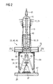
- FIG. 1 is a stored on two trestles 11 rotor 13 a heavy stationary gas turbine shown.
- the rotor 13 includes a tie rod 15 which extends centrally through a plurality of turbine disks 17 and compressor disks 19.
- the compressor-side end of the rotor 13 is shown on the left.
- the turbine disks 17 and the compressor disks 19 are rotor disks 21 and wear at their outer ends blades, which are a compressible flow medium of the gas turbine exposed.
- a front hollow shaft 22 is screwed onto the tie rod 15 at the compressor-side end 33 of the rotor 13.
- a nut 24 is provided.
- a mounting device 23 is provided in addition to the two bearing blocks 11, which is arranged rotorend perfume.
- the mounting device 23 comprises a turning bracket 27 which is mounted on a foundation 29.
- the turning block 27 is set up in alignment with the two bearing blocks 11 and has at its tip a joint 31 which is connected to the compressor-side end 33 of the rotor 13.
- the rotor 13 is rotatable about an axis of rotation parallel to the horizontal plane 47 of the joint 31.
- the joint 31 comprises a roller-mounted receptacle for a rotatable about a vertical axis 35 turntable 37. On the vertical axis 35 is also the Rotorabstütztician.
- a trailer nut 41 is mounted on the means of a shackle the rope of a crane can be struck.
- the mounting device 23 further comprises a securing device 45 designed as a frame 43, which is anchored separately in the foundation 29 by the turning block 27.
- the framework 43 comprises a platform 49 or work platform jacked up on four vertical supports 64.
- further struts 65 extending transversely to the supports 64 are provided on each side edge of the framework 43, which additionally connect the foundation-side ends of the supports 64 to the platform 49.
- part of the platform 49 and the struts 65 arranged underneath can be moved out of the pivoting range of the rotor 13.
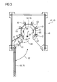
- the platform 49 and the securing device 45 then have an opened receptacle (cf. FIG. 3 ).
- FIG. 3 The plan view of the platform 49 of the securing device 45 show the Figures 3 and 4 , in which FIG. 3 the open to receive the rotor 13 platform 49 shows and FIG. 4 the closed platform 49 with centrally arranged tie rod 15 and front hollow shaft 22 according to the sectional view IV-IV of FIG. 2 ,
- a centrally disposed opening 51 is provided, in which an axial portion of the hollow shaft 22 can be inserted.
- the opening 51 is enclosed by a segmented ring 53, whose first segment 55 comprises a segmental arc of approximately 270 ° and whose second segment 57 comprises a segmental arc of approximately 90 °.
- the second ring segment 57 is pivotable relative to the first ring segment 55 about an axis of rotation 59, which serves for easy and quick closing and opening of the ring 53 (see. FIG. 4 ). Both segments 55, 57 each have an inwardly directed support surface 61, which can each be applied to a portion of the lateral surface of the rotor 13 and the tie rod 15.
- the ring 53 lies in a plane parallel to the horizontal plane 47, ie parallel to the foundation 29, and can be displaced by means of an auxiliary device supporting it within this plane for vertical alignment of the rotor 13.
- the auxiliary device comprises, for example, a plurality of screw connections 63 fastened to the platform 49.
- Each of these screw connections 63 has a screw axis 67, which likewise lies in the plane parallel to the horizontal plane 47.
- the screw 63 are arranged radially with a closed ring 53, so that their screw axes 67 meet in a virtual center 66.
- screw 63 can also be provided in each case a hydraulic arrangement with a movable piston rod to laterally support the ring 53 and thereby align the rotor 13 (or tie rod 15) relative to the turn block 27 such that of this from an approximately vertical orientation in a vertical alignment can be shifted.
- the ring 53 may be mounted in a double-nested eccentric, so that the opening 51 relative to the axis 35 of the turning block 27 is arbitrarily alignable.
- the ring 53 is only optional.
- the lateral support of the rotor 13 it is also possible for the lateral support of the rotor 13 to take place directly from the screw connections 63 or directly from the piston rods of the hydraulic cylinders.
- the support surfaces 61 would then be arranged on the inwardly projecting free ends 69 of the screw 63 or the inwardly projecting free ends of the piston rods of the hydraulic cylinders, which would then be applied directly to the lateral surface of the rotor 13.
- the ring 53 and the platform 49 must first be opened.
- the second segment 57 of the ring 53 is pivotable about the rotation axis 59 according to the arrow 60 from a closed position to an open position (shown).
- those are in the FIG. 3 shown below struts 65 and the railing 70 of the platform of the platform 49 according to the arrow 62 folded away, so that a total of the receptacle is opened.
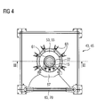
- FIG. 4 shows the top view of the securing device 45 with the almost completely closed ring 53.
- the ring 53 surrounds the hollow shaft 22 so that the support surfaces 61 abut the lateral surface of the hollow shaft 22.
- the ring 53 is displaceable over the individual screw 63 in the plane parallel to the foundation 29, so that the center of the ring 53 and thus the center of the tie rod 15 relative to the turn block 27 and thus relative to the central Rotorabstütztician is slightly displaced to the rotor thirteenth in a vertical orientation.
- the latter larger, outgoing from the rotor forces and moments and forward into the foundation as a backup device, which is mounted directly on the turning block. Larger forces can occur, for example, with comparatively smaller earthquakes, so that now the device according to the invention satisfies earthquake requirements to a certain extent.
- the scaffolding can also serve as a working platform, so that the alignment of the rotor can be performed in a perpendicular much easier by fitters.
Landscapes
- Engineering & Computer Science (AREA)
- Mechanical Engineering (AREA)
- General Engineering & Computer Science (AREA)
- Turbine Rotor Nozzle Sealing (AREA)
- Structures Of Non-Positive Displacement Pumps (AREA)
Priority Applications (12)
| Application Number | Priority Date | Filing Date | Title |
|---|---|---|---|
| EP20070007681 EP1983161A1 (de) | 2007-04-16 | 2007-04-16 | Sicherungsvorrichtung zur Sicherung eines quer gegenüber einer Horizontalebene aufgestellten Rotors einer Strömungsmaschine gegen Umkippen sowie Montagevorrichtung |
| JP2010503450A JP4937408B2 (ja) | 2007-04-16 | 2008-04-03 | 複数の回転円板から構成された流体機械におけるロータを組立および分解するための組立装置 |
| ES08735742T ES2365375T3 (es) | 2007-04-16 | 2008-04-03 | Dispositivo de montaje para el ensamblaje y desmontaje de un rotor de una turbomáquina que está compuesto por discos de rotor. |
| US12/596,215 US9003656B2 (en) | 2007-04-16 | 2008-04-03 | Securing device for securing a turbomachine rotor set up transversely to a horizontal plane against tipping over and orientation method therefor |
| AT08735742T ATE510998T1 (de) | 2007-04-16 | 2008-04-03 | Montagevorrichtung zum zusammensetzen und zerlegen eines sich aus rotorscheiben zusammensetzenden rotors einer strömungsmaschine |
| EP08735741.4A EP2134927B1 (de) | 2007-04-16 | 2008-04-03 | Sicherungsvorrichtung zur sicherung eines quer gegenüber einer horizontalebene aufgestellten rotors einer strömungsmaschine gegen umkippen sowie ausrichtverfahren dazu |
| EP20080735742 EP2134928B1 (de) | 2007-04-16 | 2008-04-03 | Montagevorrichtung zum zusammensetzen und zerlegen eines sich aus rotorscheiben zusammensetzenden rotors einer strömungsmaschine |
| JP2010503449A JP4948644B2 (ja) | 2007-04-16 | 2008-04-03 | 水平面に対して垂直に立てられた流体機械におけるロータを転倒防止するための保持装置並びにそのための鉛直に立てる方法 |
| PL08735742T PL2134928T3 (pl) | 2007-04-16 | 2008-04-03 | Urządzenie montażowe do składania i rozkładania rotora maszyny przepływowej składającego się z tarcz rotora |
| PCT/EP2008/053992 WO2008125506A1 (de) | 2007-04-16 | 2008-04-03 | Sicherungsvorrichtung zur sicherung eines quer gegenüber einer horizontalebene aufgestellten rotors einer strömungsmaschine gegen umkippen sowie ausrichtverfahren dazu |
| US12/595,556 US8667678B2 (en) | 2007-04-16 | 2008-04-03 | Assembly apparatus for assembling and dismantling a turbomachine rotor composed of rotor disks |
| PCT/EP2008/053993 WO2008125507A1 (de) | 2007-04-16 | 2008-04-03 | Montagevorrichtung zum zusammensetzen und zerlegen eines sich aus rotorscheiben zusammensetzenden rotors einer strömungsmaschine |
Applications Claiming Priority (1)
| Application Number | Priority Date | Filing Date | Title |
|---|---|---|---|
| EP20070007681 EP1983161A1 (de) | 2007-04-16 | 2007-04-16 | Sicherungsvorrichtung zur Sicherung eines quer gegenüber einer Horizontalebene aufgestellten Rotors einer Strömungsmaschine gegen Umkippen sowie Montagevorrichtung |
Publications (1)
| Publication Number | Publication Date |
|---|---|
| EP1983161A1 true EP1983161A1 (de) | 2008-10-22 |
Family
ID=38436746
Family Applications (3)
| Application Number | Title | Priority Date | Filing Date |
|---|---|---|---|
| EP20070007681 Withdrawn EP1983161A1 (de) | 2007-04-16 | 2007-04-16 | Sicherungsvorrichtung zur Sicherung eines quer gegenüber einer Horizontalebene aufgestellten Rotors einer Strömungsmaschine gegen Umkippen sowie Montagevorrichtung |
| EP08735741.4A Not-in-force EP2134927B1 (de) | 2007-04-16 | 2008-04-03 | Sicherungsvorrichtung zur sicherung eines quer gegenüber einer horizontalebene aufgestellten rotors einer strömungsmaschine gegen umkippen sowie ausrichtverfahren dazu |
| EP20080735742 Active EP2134928B1 (de) | 2007-04-16 | 2008-04-03 | Montagevorrichtung zum zusammensetzen und zerlegen eines sich aus rotorscheiben zusammensetzenden rotors einer strömungsmaschine |
Family Applications After (2)
| Application Number | Title | Priority Date | Filing Date |
|---|---|---|---|
| EP08735741.4A Not-in-force EP2134927B1 (de) | 2007-04-16 | 2008-04-03 | Sicherungsvorrichtung zur sicherung eines quer gegenüber einer horizontalebene aufgestellten rotors einer strömungsmaschine gegen umkippen sowie ausrichtverfahren dazu |
| EP20080735742 Active EP2134928B1 (de) | 2007-04-16 | 2008-04-03 | Montagevorrichtung zum zusammensetzen und zerlegen eines sich aus rotorscheiben zusammensetzenden rotors einer strömungsmaschine |
Country Status (7)
| Country | Link |
|---|---|
| US (2) | US8667678B2 (enExample) |
| EP (3) | EP1983161A1 (enExample) |
| JP (2) | JP4948644B2 (enExample) |
| AT (1) | ATE510998T1 (enExample) |
| ES (1) | ES2365375T3 (enExample) |
| PL (1) | PL2134928T3 (enExample) |
| WO (2) | WO2008125506A1 (enExample) |
Cited By (2)
| Publication number | Priority date | Publication date | Assignee | Title |
|---|---|---|---|---|
| EP3647538A1 (en) * | 2018-10-30 | 2020-05-06 | Siemens Aktiengesellschaft | Safety apparatus for containing an energy release from a rotor assembly |
| EP3647537A1 (en) * | 2018-10-30 | 2020-05-06 | Siemens Aktiengesellschaft | Safety apparatus and corresponding method for containing an energy release from a tension stud of a rotor assembly |
Families Citing this family (7)
| Publication number | Priority date | Publication date | Assignee | Title |
|---|---|---|---|---|
| GB201005351D0 (en) * | 2010-03-30 | 2010-05-12 | Rolls Royce Plc | Support frame |
| EP2570621A1 (de) | 2011-09-15 | 2013-03-20 | Siemens Aktiengesellschaft | Vorrichtung zum Schwenken eines Rotors einer Strömungsmaschine aus einer ersten Lage in eine zweite Lage |
| EP2667493B1 (en) * | 2012-05-21 | 2019-11-20 | Siemens Gamesa Renewable Energy A/S | Method of vertically assembling a generator of a wind turbine |
| DE102014200760A1 (de) * | 2014-01-17 | 2015-07-23 | Siemens Aktiengesellschaft | Läuferschwenksystem |
| JP6238217B2 (ja) * | 2014-11-19 | 2017-11-29 | 三菱日立パワーシステムズ株式会社 | ガスタービンのメインテナンス方法 |
| KR101871061B1 (ko) * | 2016-11-17 | 2018-06-25 | 두산중공업 주식회사 | 가스 터빈 및 상기 가스 터빈의 베어링 교체 방법 |
| JP7274942B2 (ja) * | 2019-05-31 | 2023-05-17 | 三菱重工業株式会社 | ロータ組立方法、ロータディスク保持治具及びロータスタンド |
Citations (3)
| Publication number | Priority date | Publication date | Assignee | Title |
|---|---|---|---|---|
| DE2325642A1 (de) * | 1972-05-24 | 1973-12-06 | Rolls Royce 1971 Ltd | Gasturbinenanlage |
| DE2426231A1 (de) * | 1974-05-29 | 1975-12-04 | Kraftwerk Union Ag | Vorrichtung zum wenden und aufrichten von turbinenlaeufern |
| WO2000017492A1 (en) * | 1998-09-24 | 2000-03-30 | Ramgen Power Systems, Inc. | Modular multi-part rail mounted engine assembly |
Family Cites Families (15)
| Publication number | Priority date | Publication date | Assignee | Title |
|---|---|---|---|---|
| US2930492A (en) * | 1957-07-23 | 1960-03-29 | Orenda Engines Ltd | Work stand and loading apparatus |
| DE2026254A1 (en) * | 1969-06-23 | 1971-01-07 | VEB Bergmann Borsig/Gorhtzer Ma schinenbau, χ 1000 Berlin Wilhelmsruh | Welding device with pivotal stand for fluid - flow engine armatures |
| JPS5072734A (enExample) | 1973-10-30 | 1975-06-16 | ||
| JPS51134107A (en) * | 1975-05-16 | 1976-11-20 | Matsushita Electric Ind Co Ltd | Recording stylus |
| DE3118073A1 (de) * | 1981-05-07 | 1982-11-25 | Hoechst Ag, 6000 Frankfurt | Diphenylaether-azoverbindungen, verfahren zu ihrer herstellung und ihre verwendung als farbstoffe |
| JPS6044267A (ja) | 1983-08-20 | 1985-03-09 | Toyota Motor Corp | 溶射層の密着性向上方法 |
| JPS61161823A (ja) * | 1985-01-10 | 1986-07-22 | Nec Corp | 入力回路 |
| JPH0721261B2 (ja) * | 1986-10-13 | 1995-03-08 | 三機工業株式会社 | ポ−ル垂直建方調整治具 |
| JPH0227071A (ja) * | 1988-07-18 | 1990-01-29 | Sanki Eng Co Ltd | ポール垂直建方調整治具 |
| JPH0572734A (ja) | 1991-09-11 | 1993-03-26 | Mitsubishi Petrochem Co Ltd | 感光性樹脂組成物 |
| JPH0882117A (ja) | 1994-09-09 | 1996-03-26 | Masahito Kajii | 可倒ポール装置 |
| JP2780736B2 (ja) * | 1995-02-13 | 1998-07-30 | 山崎 勝己 | ポール支持装置 |
| JPH11323962A (ja) * | 1998-05-13 | 1999-11-26 | Kohan Kenzai Kk | 建付け調整具及び同建付け調整具を用いた建付け方法 |
| JP2001234646A (ja) * | 2000-02-24 | 2001-08-31 | Kyouyou:Kk | 鉄塔とこの鉄塔の形成方法 |
| JP5072734B2 (ja) | 2008-06-26 | 2012-11-14 | 三菱電機株式会社 | 永久磁石型回転電機およびパワーステアリング装置 |
-
2007
- 2007-04-16 EP EP20070007681 patent/EP1983161A1/de not_active Withdrawn
-
2008
- 2008-04-03 US US12/595,556 patent/US8667678B2/en not_active Expired - Fee Related
- 2008-04-03 JP JP2010503449A patent/JP4948644B2/ja not_active Expired - Fee Related
- 2008-04-03 PL PL08735742T patent/PL2134928T3/pl unknown
- 2008-04-03 WO PCT/EP2008/053992 patent/WO2008125506A1/de not_active Ceased
- 2008-04-03 ES ES08735742T patent/ES2365375T3/es active Active
- 2008-04-03 WO PCT/EP2008/053993 patent/WO2008125507A1/de not_active Ceased
- 2008-04-03 AT AT08735742T patent/ATE510998T1/de active
- 2008-04-03 EP EP08735741.4A patent/EP2134927B1/de not_active Not-in-force
- 2008-04-03 EP EP20080735742 patent/EP2134928B1/de active Active
- 2008-04-03 US US12/596,215 patent/US9003656B2/en not_active Expired - Fee Related
- 2008-04-03 JP JP2010503450A patent/JP4937408B2/ja not_active Expired - Fee Related
Patent Citations (3)
| Publication number | Priority date | Publication date | Assignee | Title |
|---|---|---|---|---|
| DE2325642A1 (de) * | 1972-05-24 | 1973-12-06 | Rolls Royce 1971 Ltd | Gasturbinenanlage |
| DE2426231A1 (de) * | 1974-05-29 | 1975-12-04 | Kraftwerk Union Ag | Vorrichtung zum wenden und aufrichten von turbinenlaeufern |
| WO2000017492A1 (en) * | 1998-09-24 | 2000-03-30 | Ramgen Power Systems, Inc. | Modular multi-part rail mounted engine assembly |
Cited By (9)
| Publication number | Priority date | Publication date | Assignee | Title |
|---|---|---|---|---|
| EP3647538A1 (en) * | 2018-10-30 | 2020-05-06 | Siemens Aktiengesellschaft | Safety apparatus for containing an energy release from a rotor assembly |
| EP3647537A1 (en) * | 2018-10-30 | 2020-05-06 | Siemens Aktiengesellschaft | Safety apparatus and corresponding method for containing an energy release from a tension stud of a rotor assembly |
| WO2020088811A1 (en) * | 2018-10-30 | 2020-05-07 | Siemens Aktiengesellschaft | Safety apparatus and corresponding method for containing an energy release from a tension stud of a rotor assembly |
| WO2020088809A1 (en) * | 2018-10-30 | 2020-05-07 | Siemens Aktiengesellschaft | Safety apparatus for containing an energy release from a rotor assembly |
| CN112955630A (zh) * | 2018-10-30 | 2021-06-11 | 西门子能源环球有限责任两合公司 | 用于容纳来自转子组件的张力螺柱的能量释放的安全装置和对应方法 |
| CN112955629A (zh) * | 2018-10-30 | 2021-06-11 | 西门子能源环球有限责任两合公司 | 用于容纳来自转子组件的能量释放的安全装置 |
| US11519301B2 (en) | 2018-10-30 | 2022-12-06 | Siemens Energy Global GmbH & Co. KG | Safety apparatus and corresponding method for containing an energy release from a tension stud of a rotor assembly |
| CN112955629B (zh) * | 2018-10-30 | 2023-03-10 | 西门子能源环球有限责任两合公司 | 用于容纳来自转子组件的能量释放的安全装置 |
| US11795835B2 (en) | 2018-10-30 | 2023-10-24 | Siemens Energy Global GmbH & Co. KG | Safety apparatus for containing an energy release from a rotor assembly |
Also Published As
| Publication number | Publication date |
|---|---|
| EP2134927A1 (de) | 2009-12-23 |
| US8667678B2 (en) | 2014-03-11 |
| JP4948644B2 (ja) | 2012-06-06 |
| US20100139064A1 (en) | 2010-06-10 |
| EP2134927B1 (de) | 2017-03-08 |
| PL2134928T3 (pl) | 2011-10-31 |
| EP2134928A1 (de) | 2009-12-23 |
| ES2365375T3 (es) | 2011-10-03 |
| WO2008125506A1 (de) | 2008-10-23 |
| US9003656B2 (en) | 2015-04-14 |
| JP2010523901A (ja) | 2010-07-15 |
| WO2008125507A1 (de) | 2008-10-23 |
| JP4937408B2 (ja) | 2012-05-23 |
| JP2010523900A (ja) | 2010-07-15 |
| ATE510998T1 (de) | 2011-06-15 |
| EP2134928B1 (de) | 2011-05-25 |
| US20100107385A1 (en) | 2010-05-06 |
Similar Documents
| Publication | Publication Date | Title |
|---|---|---|
| EP2134927B1 (de) | Sicherungsvorrichtung zur sicherung eines quer gegenüber einer horizontalebene aufgestellten rotors einer strömungsmaschine gegen umkippen sowie ausrichtverfahren dazu | |
| EP1825141B1 (de) | Windenergieanlage mit halteeinrichtung für eine rotorwelle | |
| DE102010062418B9 (de) | Verfahren und Vorrichtung zum Verdrehen eines Roboterblattlagers an Windenergieanlagen ohne Einsatz eines Autokranes | |
| EP2742213B1 (de) | Vorrichtung zum schwenken eines rotors einer strömungsmaschine aus einer ersten lage in eine zweite lage | |
| EP2610439A1 (de) | Verfahren zum Ziehen und/oder Einsetzen eines Turbinenlagers sowie Vorrichtung zur Durchführung des Verfahrens | |
| DE3750572T2 (de) | Modulares gerüstsystem und verbindungselemente dafür. | |
| EP2278128A2 (de) | Gasturbine mit Abgasgehäuse sowie Verfahren zum Herstellen einer solchen Gasturbine | |
| WO2016078926A1 (de) | Gasturbine mit hebevorrichtung | |
| EP2177670A1 (de) | Oberwagenkonstruktion eines verfahrbaren Arbeitsgerätes | |
| EP3538745B1 (de) | Verfahren zur montage und/oder demontage von komponenten einer ein turbinengehäuse aufweisenden turbine sowie adapter und system zur verwendung in dem verfahren | |
| EP2978942B1 (de) | Kragträgerschlitten für montage und demontage eines rotorblocks | |
| DE202021106818U1 (de) | Mobilkran mit einer Gegengewichtsvorrichtung | |
| DE102013203793A1 (de) | Gondelgestell und Verfahren für Montage und Prüfung einer Gondel für eine Windenergieanlage | |
| EP3051077A1 (de) | Montagevorrichtung zur montage oder demontage einer gasturbinenkomponente bei einer gasturbine, insbesondere von einer brennerkomponente bei einem brennersystem einer gasturbine | |
| EP0369938B1 (de) | Verfahren und Vorrichtung zur Demolierung von Mauerwerken | |
| EP3562628B1 (de) | Verfahren zur montage und/oder demontage von brennern, vorrichtung zur verwendung in dem verfahren sowie anordnung | |
| DE29812795U1 (de) | Vorrichtung zum Abbrechen eines eine umlaufende Wandung aufweisenden Bauwerks wie einem Schornstein oder einem Kühlturm | |
| DE202022105371U1 (de) | Hubvorrichtung für ein Ringsegment, Anordnung mit einer solchen Hubvorrichtung, und Anwendung der Hubvorrichtung | |
| EP3622164B1 (de) | Aufhängungssystem für eine gasturbine und zugehörige gasturbine | |
| EP1830006B1 (de) | Bauarbeitsvorrichtung und Verfahren zur Bereitstellung eines Transportzustands für eine Bauarbeitsvorrichtung | |
| DE102020118713A1 (de) | Verfahren zum Herstellen einer Windenergieanlage, Windenergieanlage sowie Torsionsaufnahme | |
| EP1342885B1 (de) | Thermische Turbomaschine, insbesondere Axialdurchströmte Gasturbine | |
| DE102010064637B3 (de) | Verfahren zur Instandhaltung einer Windenergieanlage, Zwischenstück und Verfahren zur Verwendung mindestens eines solchen Zwischenstücks | |
| EP3438450B1 (de) | Plattform für wartungsarbeiten an einer windenergieanlage, verfahren zur montage einer solchen plattform und windenergieanlage | |
| CH702182A1 (de) | Gasturbine mit abgasgehäuse sowie verfahren zum herstellen einer solchen gasturbine. |
Legal Events
| Date | Code | Title | Description |
|---|---|---|---|
| PUAI | Public reference made under article 153(3) epc to a published international application that has entered the european phase |
Free format text: ORIGINAL CODE: 0009012 |
|
| AK | Designated contracting states |
Kind code of ref document: A1 Designated state(s): AT BE BG CH CY CZ DE DK EE ES FI FR GB GR HU IE IS IT LI LT LU LV MC MT NL PL PT RO SE SI SK TR |
|
| AX | Request for extension of the european patent |
Extension state: AL BA HR MK RS |
|
| AKX | Designation fees paid | ||
| STAA | Information on the status of an ep patent application or granted ep patent |
Free format text: STATUS: THE APPLICATION IS DEEMED TO BE WITHDRAWN |
|
| 18D | Application deemed to be withdrawn |
Effective date: 20090424 |
|
| REG | Reference to a national code |
Ref country code: DE Ref legal event code: 8566 |