EP1983130A2 - Fundament für einen Mast - Google Patents
Fundament für einen Mast Download PDFInfo
- Publication number
- EP1983130A2 EP1983130A2 EP08003151A EP08003151A EP1983130A2 EP 1983130 A2 EP1983130 A2 EP 1983130A2 EP 08003151 A EP08003151 A EP 08003151A EP 08003151 A EP08003151 A EP 08003151A EP 1983130 A2 EP1983130 A2 EP 1983130A2
- Authority
- EP
- European Patent Office
- Prior art keywords
- attachment
- foundation
- mast
- recess
- foundation according
- Prior art date
- Legal status (The legal status is an assumption and is not a legal conclusion. Google has not performed a legal analysis and makes no representation as to the accuracy of the status listed.)
- Granted
Links
Images

Classifications
-
- E—FIXED CONSTRUCTIONS
- E02—HYDRAULIC ENGINEERING; FOUNDATIONS; SOIL SHIFTING
- E02D—FOUNDATIONS; EXCAVATIONS; EMBANKMENTS; UNDERGROUND OR UNDERWATER STRUCTURES
- E02D27/00—Foundations as substructures
- E02D27/32—Foundations for special purposes
- E02D27/42—Foundations for poles, masts or chimneys
-
- E—FIXED CONSTRUCTIONS
- E04—BUILDING
- E04H—BUILDINGS OR LIKE STRUCTURES FOR PARTICULAR PURPOSES; SWIMMING OR SPLASH BATHS OR POOLS; MASTS; FENCING; TENTS OR CANOPIES, IN GENERAL
- E04H12/00—Towers; Masts or poles; Chimney stacks; Water-towers; Methods of erecting such structures
- E04H12/22—Sockets or holders for poles or posts
- E04H12/2253—Mounting poles or posts to the holder
- E04H12/2269—Mounting poles or posts to the holder in a socket
-
- E—FIXED CONSTRUCTIONS
- E04—BUILDING
- E04B—GENERAL BUILDING CONSTRUCTIONS; WALLS, e.g. PARTITIONS; ROOFS; FLOORS; CEILINGS; INSULATION OR OTHER PROTECTION OF BUILDINGS
- E04B1/00—Constructions in general; Structures which are not restricted either to walls, e.g. partitions, or floors or ceilings or roofs
- E04B1/18—Structures comprising elongated load-supporting parts, e.g. columns, girders, skeletons
- E04B1/20—Structures comprising elongated load-supporting parts, e.g. columns, girders, skeletons the supporting parts consisting of concrete, e.g. reinforced concrete, or other stonelike material
- E04B1/21—Connections specially adapted therefor
- E04B1/215—Connections specially adapted therefor comprising metallic plates or parts
Definitions
- the invention relates to a foundation for a mast, especially for floodlit pylons for snow-covered slopes.
- the object of the invention is therefore to substantially reduce the cost of erecting such masts in rough terrain.
- the foundation according to the invention consists of two precast concrete parts, namely a foundation plate and a quiver-shaped attachment with a recess for receiving the mast base.
- the mast is a floodlight mast, which is installed on a ski slope or the like terrain with a snowmaking system, preferably a shaft part is added as the third precast concrete part.
- These parts have a maximum weight of 3, preferably a maximum of 2 tons and can use it For example, be transported by a tracked vehicle, such as an excavator, in rough terrain.
- mounting inserts are cast in concrete, which at the lower end a plate, a web or the like. Have.
- the plates or the like. Sections are provided with an opening through which the bolt is placed on the foundation plate on which a nut is screwed, with which the mounting insert and thus the attachment is pulled firmly against the foundation plate.
- the inserts including the plate or the like at the lower end are preferably made of steel.
- the mounting inserts are provided in arranged on the periphery of the essay mounting recesses, which are accessible via an opening from the outside, to screw the nut on the bolts can.
- the mounting recesses are made with steel bodies, which are removed after stripping the attachment.
- the mounting inserts preferably have a wall portion which is arranged on the side opposite the mounting opening side of the mounting recesses.
- the wall portion extends upward and is preferably formed angular.
- the mounting insert is anchored with a reinforcement in the essay.
- the mounting insert is connected to a vertically extending in the tower reinforcement.
- the essay has more Reinforcements.
- the foundation plate and the shaft part is preferably provided with a steel reinforcement.
- the bolts in the foundation plate preferably project through a setting template which is concreted in on the upper side of the foundation plate and which is preferably designed as a rectangular, in particular square, frame. In each case at least one bolt is arranged at each corner and between the corners.
- the setting template ensures that the bolts are embedded in the foundation plate properly arranged.
- the quiver-shaped attachment is preferably also in cross-section also rectangular or square executed substantially with the same outer dimensions as the setting template, so that the mounting recesses lie on the essay at the corners, in each case at least one mounting recess is provided between the corners.
- the vertically extending through the attachment recess for receiving the mast base has in the lower region of the essay on a conically tapering portion with a diameter corresponding to the outer diameter of the mast base.
- the conical section preferably has a circular cross-section, for example in order to avoid to receive a cylindrical or possibly polygonal, for example, hexagonal mast base.
- the foundation plate is laid horizontally aligned in a pit on a percolating packet and attached to the essay, preferably under the floor, so that the upper end of the essay is flush with the ground surface or below.
- the mast is eg with a Helicopter is inserted with his foot in the mast recess in the attachment until he gets up on the foundation plate. He is centered by the conically tapered section. Then the mast is aligned vertically with wooden wedges at the upper end of the recess and filled the extended area between the mast and the inner wall with grit or the like aggregate to a certain height, whereupon the remaining space is poured over the aggregate after removal of the wooden wedges with concrete.
- a drainage opening is provided in the foundation plate.
- an opening extending from the outside into the mast recess for carrying out the mast cabling, that is to say the power supply of the luminaire.
- a lateral passage opening e.g. be provided for a control line and / or a load feed.
- the invention is preferably intended for the floodlight masts of a snow-covered area, for example a ski slope.
- the shaft part is provided according to the invention, which is supported on the foundation plate and connected to the attachment.
- the shaft part is closed at the top with a blanket or a lid and for receiving the electrical and hydraulic supply equipment of the snow-making system, e.g. a snow cannon.
- the shaft part has the same height as the attachment, so it is preferably designed like this as Unterfl medium.
- the shaft part has, on the ceiling, preferably on the side facing the attachment, a recess for a retractable electronic connection column, optionally with a water connection for the snow-making system. That is, the electrical and / or hydraulic water side can be pulled upwards from the recess in the ceiling for connection to the snow gun.
- the shaft part in the ceiling on an access hatch is accessible.
- the essay facing wall of the shaft portion is provided with a recess into which protrudes the attachment.
- To attach the sub-floor shaft to the essay angle iron can be provided with which the underfloor shaft is screwed to the essay.
- rails are provided on the inner walls of the shaft part, where, for example, cabinets can be attached.
- the interior of the shaft part expands from top to bottom to be easier to remove when stripping the core formwork can.
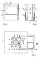
- the foundation has a foundation plate 1 ( Fig. 1, 2 . 4 and 5 ), an essay 2 ( Fig. 3, 4 and 5 ) and optionally a shaft part (3) ( 4 and 6 ), which are formed by precast concrete parts.
- the mounting inserts 5 are provided on the circumference of the attachment 2 in mounting recesses 9, which are accessible via an opening 10 from the outside, in order to screw the nuts 8 on the bolts 4 can.
- the mounting inserts 5 have an angular wall portion 12, which is arranged on the inside of the mounting recess 9, which is opposite to the opening 10.
- the mounting recesses 9 are formed in cross-section substantially rectangular.
- the mounting inserts 5 are anchored with a concreted into the essay 2, substantially vertically extending reinforcements 13.
- Fig. 1 it can be seen, protrude through the bolts 4 in the foundation plate 1 a cast-in at the top of the foundation plate 1 setting template 14, which is formed as a square frame.
- a screw bolt 4 is arranged at each corner and between the corners of the template 14.
- the attachment 2 is also formed in cross section square with the same outer dimensions as the setting template 14, so that the mounting recesses 9 are on the attachment 2 at the corners of the attachment 2, wherein a mounting recess 9 is provided between the corners.
- the quiver-shaped attachment 2 extends vertically in the middle of a recess 15 from bottom to top.
- the continuous recess 15 is concentric with the longitudinal axis of the Attachment 2 arranged.
- the recess 15 has in the lower region of the attachment 2 to a conically tapered portion 16 which has a diameter at the lower end 11, which corresponds to the outer diameter of the mast base, not shown.
- a drainage opening 17 is provided in the foundation plate 2 in the middle.
- an opening 18 extending from the outside into the recess 15 is provided for carrying out the mast cabling, furthermore a lateral passage opening 19 for the control line and the load feed.
- the shaft part 3 which is closed at the top with a cover 21, serves to accommodate the electrical and hydraulic supply devices of a snow gun.
- the essay 2 facing wall of the shaft part 3 is provided with a recess 22 into which the attachment 2 protrudes ( Fig. 4 ).
- two angle iron 23 are provided, which are screwed to the shaft part 3 and the attachment 2, respectively.
- the ceiling 21 of the shaft part 3 has on the attachment 2 side facing a recess 24 for a retractable electronics and / or hydraulic connection of the snow gun. Furthermore, an access hatch 25 is provided in the ceiling 21 of the shaft part 3. The access hatch 25 can be closed with a lid, not shown. To the Inner walls of the shaft part 2 Halfen rails 26 are attached to which cabinets can be attached.
Landscapes
- Engineering & Computer Science (AREA)
- Architecture (AREA)
- Civil Engineering (AREA)
- Structural Engineering (AREA)
- Life Sciences & Earth Sciences (AREA)
- General Life Sciences & Earth Sciences (AREA)
- Mining & Mineral Resources (AREA)
- Paleontology (AREA)
- General Engineering & Computer Science (AREA)
- Foundations (AREA)
Abstract
Description
- Die Erfindung bezieht sich auf ein Fundament für einen Mast, insbesondere für Flutlichtmasten für beschneite Pisten.
- Für die Flutlichtmasten in einem unwegsamen Gelände, wie Skipisten, werden heutzutage die Fundamente an der Skipiste betoniert. Dazu werden Hubschrauber eingesetzt, die den Beton vom Betonmischwagen z.B. im Tal zur Baustelle befördern. Der Einsatz von Hubschraubern ist notwendig, damit der Beton nicht vorher abbindet. Durch das erhebliche Gewicht des Betongemischs, der Schalung und weiterer Einrichtungen ist der Hubschraubertransport mit erheblichen Kosten verbunden.
- Aufgabe der Erfindung ist es daher, die Kosten der Errichtung solcher Masten im unwegsamen Gelände wesentlich zu verringern.
- Dies wird erfindungsgemäß durch das im Anspruch 1 gekennzeichnete Fundament erreicht. In den Unteransprüchen sind vorteilhafte Ausgestaltungen der Erfindung wiedergegeben.
- Das erfindungsgemäße Fundament besteht aus zwei Betonfertigteilen, nämlich einer Fundamentplatte und einem köcherförmigen Aufsatz mit einer Ausnehmung zur Aufnahme des Mastfußes. Falls der Mast ein Flutlichtmast ist, der an einer Skipiste oder dergleichen Gelände mit einer Beschneiungsanlage installiert wird, kommt vorzugsweise ein Schachtteil als drittes Betonfertigteil hinzu. Diese Teile haben ein Gewicht von maximal 3, vorzugsweise maximal 2 Tonnen und können damit beispielsweise von einem Kettenfahrzeug, wie einem Bagger, im unwegsamen Gelände transportiert werden.
- Zur Befestigung des Aufsatzes auf der Fundamentplatte sind in die Fundamentplatte senkrechte Schraubenbolzen einbetoniert, die an der Oberseite der Fundamentplatte herausragen.
- Zum anderen sind in den Aufsatz am unteren Ende Montageeinlegeteile einbetoniert, die am unteren Ende eine Platte, einen Steg oder dgl. aufweisen. Die Platten oder dgl. Abschnitte sind mit einer Öffnung versehen, durch die der Schraubbolzen an der Fundamentplatte gesteckt wird, auf den eine Mutter geschraubt wird, mit der das Montageeinlegeteil und damit der Aufsatz fest gegen die Fundamentplatte gezogen wird. Die Einlegeteile einschließlich der Platte oder dgl. am unteren Ende bestehen vorzugsweise aus Stahl.
- Die Montageeinlegeteile sind in am Umfang des Aufsatzes angeordneten Montageausnehmungen vorgesehen, die über eine Öffnung von außen zugänglich sind, um die Mutter auf die Schraubbolzen aufschrauben zu können. Die Montageausnehmungen werden mit Stahlkörpern hergestellt, die nach dem Ausschalen des Aufsatzes entfernt werden.
- Die Montageeinlegeteile weisen vorzugsweise einen Wandabschnitt auf, der an der der Montageöffnung gegenüberliegenden Seite der Montageausnehmungen angeordnet ist. Der Wandabschnitt erstreckt sich nach oben und ist vorzugsweise winkelförmig ausgebildet.
- Das Montageeinlegeteil ist mit einer Bewehrung in dem Aufsatz verankert. Dazu ist das Montageeinlegeteil mit einer sich im Aufsatz senkrecht erstreckenden Bewehrung verbunden. Zur Erhöhung der Zugfestigkeit weist der Aufsatz weitere Bewehrungen auf. Ebenso ist die Fundamentplatte und das Schachtteil vorzugsweise mit einer Stahlbewehrung versehen.
- Die Schraubbolzen in der Fundamentplatte durchragen vorzugsweise eine auf der Oberseite der Fundamentplatte einbetonierte Setzschablone, die vorzugsweise als rechtwinkliger, insbesondere quadratischer Rahmen ausgebildet ist. Dabei ist an jeder Ecke und zwischen den Ecken jeweils mindestens ein Schraubbolzen angeordnet. Mit der Setzschablone wird sichergestellt, dass die Schraubbolzen in der Fundamentplatte richtig angeordnet einbetoniert werden.
- Der köcherförmige Aufsatz ist vorzugsweise im Querschnitt ebenfalls rechtwinklig bzw. quadratisch im wesentlichen mit den gleichen Außenabmessungen wie die Setzschablone ausgeführt, sodass die Montageausnehmungen am Aufsatz an den Ecken liegen, wobei jeweils wenigstens eine Montageausnehmung zwischen der Ecken vorgesehen ist.
- Die sich senkrecht durch den Aufsatz erstreckende Ausnehmung zur Aufnahme des Mastfußes weist im unteren Bereich des Aufsatzes einen sich konisch verjüngenden Abschnitt mit einem Durchmesser auf, der dem Außendurchmesser des Mastfußes entspricht. Der konische Abschnitt weist vorzugsweise einen kreisförmigen Querschnitt auf, um z.B. einen zylindrischen oder gegebenenfalls mehreckigen, beispielsweise sechseckigen Mastfuß aufzunehmen.
- Zur Montage wird die Fundamentplatte in einer Baugrube auf einem Sickerpaket waagrecht ausgerichtet verlegt und darauf der Aufsatz befestigt, und zwar vorzugsweise unter Flur, also so, dass das obere Ende des Aufsatzes mit der Erdbodenoberfläche abschließt oder darunter liegt. Nach Verfüllen der Baugrube wird der Mast z.B. mit einem Hubschrauber mit seinem Fuß in die Mastausnehmung in dem Aufsatz eingeführt, bis er auf der Fundamentplatte aufsteht. Dabei wird er durch den sich konisch verjüngende Abschnitt zentriert. Dann wird der Mast mit Holzkeilen an dem oberen Ende der Ausnehmung senkrecht ausgerichtet und der erweiterte Bereich zwischen Mastfuß und Innenwand mit Splitt oder dergleichen Zuschlagstoff bis zu einer bestimmten Höhe verfüllt, worauf der verbleibende Raum über den Zuschlagstoff nach Entfernen der Holzkeile mit Beton vergossen wird.
- Zur Entwässerung der Mastausnehmung in dem Aufsatz ist in der Fundamentplatte eine Entwässerungsöffnung vorgesehen. Zudem ist z.B. bei einem Flutlichtmast in dem Aufsatz eine sich von außen in die Mastausnehmung erstreckende Öffnung zur Durchführung der Mastverkabelung, also der Stromversorgung der Leuchte, vorgesehen. Ferner kann eine seitliche Durchgangsöffnung z.B. für eine Steuerleitung und/oder eine Lasteinspeisung vorgesehen sein.
- Vorzugsweise ist die Erfindung für die Flutlichtmasten eines beschneiten Geländes, beispielsweise einer Skipiste bestimmt. Dazu ist erfindungsgemäß das Schachtteil vorgesehen, das sich auf der Fundamentplatte abstützt und an dem Aufsatz angeschlossen ist. Das Schachtteil ist oben mit einer Decke oder einem Deckel verschlossen und zur Aufnahme der elektrischen und hydraulischen Versorgungseinrichtungen der Beschneiungsanlage, z.B. einer Schneekanone bestimmt.
- Das Schachtteil weist die gleiche Höhe wie der Aufsatz auf, ist also vorzugsweise wie dieser als Unterflurteil ausgebildet.
- Im Gegensatz zum Stand der Technik, wonach für das Flutlicht und die Schneekanonen jeweils eine separate Linienführung und separate Anspeisungspunkte vorgesehen sein müssen, die zudem jeweils mit entsprechenden Sicherheitseinrichtungen, beispielsweise einer Polsterung, ausgerüstet werden müssen, sind erfindungsgemäß die Linienführung und die Anspeisungspunkte für das Flutlicht und die Schneekanonen zusammengefasst.
- Das Schachtteil weist an der Decke vorzugsweise an der dem Aufsatz zugewandten Seite eine Ausnehmung für eine versenkbare Elektronikanschlusssäule gegebenenfalls mit Wasseranschluss für die Beschneiungsanlage auf. Das heißt, die Elektrik und/oder hydraulische Wasserseite kann zum Anschluss an die Schneekanone nach oben aus der Ausnehmung in der Decke gezogen werden.
- Darüber hinaus weist das Schachtteil in der Decke eine Einstiegsluke auf. Damit sind die Feldleitung, die Steuerleitung sowie die Wasser- und Luftzuführleitung für die Schneekanone zugänglich. Die dem Aufsatz zugewandte Wand des Schachtteils ist mit einer Ausnehmung versehen, in die der Aufsatz ragt. Zur Befestigung des Unterflurschachts an dem Aufsatz können Winkeleisen vorgesehen sein, mit denen der Unterflurschacht an dem Aufsatz angeschraubt wird.
- Weiterhin sind an den Innenwänden des Schachtteils Schienen vorgesehen, an denen beispielsweise Schaltschränke befestigt werden können.
- Das Innere des Schachtteils erweitert sich von oben nach unten, um beim Ausschalen die Kernschalung leichter entfernen zu können.
- Nachstehend ist eine Ausführungsform der Erfindung anhand der Zeichnung beispielhaft näher erläutert.
- Darin zeigen:
-
Fig. 1 eine Draufsicht auf eine Fundamentplatte; -
Fig. 2 einen Schnitt entlang der Linie II-II inFig. 1 ; -
Fig. 3 einen Längsschnitt durch den Aufsatz; -
Fig. 4 einen Querschnitt entlang der Linie IV-IV inFig. 3 mit dem Schachtteil und der Fundamentplatte; -
Fig. 5 einen vergrößerten Längsschnitt der aneinander befestigten Abschnitte von Aufsatz und Fundamentplatte; und -
Fig. 6 einen Längsschnitt durch das Schachtteil entlang der Linie VI-VI nachFig. 4 . - Das Fundament weist eine Fundamentplatte 1 (
Fig. 1, 2 ,4 und5 ), einen Aufsatz 2 (Fig. 3, 4 und5 ) sowie gegebenenfalls ein Schachtteil (3) (Fig. 4 und 6 ) auf, die durch Betonfertigteile gebildet sind. - Zur Befestigung des Aufsatzes 2 auf der Fundamentplatte 1 sind in die Fundamentplatte 1 senkrechte Schraubenbolzen 4 einbetoniert, die aus der Oberseite der Fundamentplatte herausragen (
Fig. 2 ). Zum anderen sind in dem Aufsatz 2 am unteren Ende Montageeinlegeteile 5 einbetoniert, die unten durch einen plattenförmigen Abschnitt 6 abgeschlossen werden (Fig. 3 und5 ). Die Platte 6 ist mit einer Öffnung 7 versehen durch die die Schraubbolzen 4 an der Fundamentplatte 1 gesteckt sind. Wie ausFig. 5 ersichtlich, sind auf die aus den Öffnungen 7 ragenden Schraubbolzen 4 Muttern 8 geschraubt, wodurch die Montageeinlegeteile 5 an dem Aufsatz 2 fest gegen die Fundamentplatte 1 gezogen werden können. - Gemäß
Fig. 3 bis 5 sind die Montageeinlegeteile 5 am Umfang des Aufsatzes 2 in Montageausnehmungen 9 vorgesehen, die über eine Öffnung 10 von außen zugänglich sind, um die Muttern 8 auf die Schraubbolzen 4 aufschrauben zu können. - Die Montageeinlegeteile 5 weisen einen winkelförmigen Wandabschnitt 12 auf, der an der Innenseite der Montageausnehmung 9 angeordnet ist, die der Öffnung 10 gegenüberliegt. Die Montageausnehmungen 9 sind im Querschnitt im wesentlichen rechteckig ausgebildet.
- Die Montageeinlegeteile 5 sind mit einer in den Aufsatz 2 einbetonierten, im wesentlichen senkrecht verlaufenden Bewehrungen 13 verankert.
- Wie insbesondere aus
Fig. 1 ersichtlich, durchragen die Schraubbolzen 4 in der Fundamentplatte 1 eine an der Oberseite der Fundamentplatte 1 einbetonierte Setzschablone 14, die als quadratischer Rahmen ausgebildet ist. Dabei ist an jeder Ecke und zwischen den Ecken der Schablone 14 jeweils ein Schraubbolzen 4 angeordnet. - Der Aufsatz 2 ist ebenfalls im Querschnitt quadratisch mit den gleichen Außenabmessungen wie die Setzschablone 14 ausgebildet, sodass die Montageausnehmungen 9 am Aufsatz 2 an den Ecken des Aufsatzes 2 liegen, wobei eine Montageausnehmung 9 zwischen den Ecken vorgesehen ist.
- Durch den köcherförmigen Aufsatz 2 erstreckt sich in der Mitte senkrecht eine Ausnehmung 15 von unten nach oben. Die durchgehende Ausnehmung 15 ist konzentrisch zur Längsachse des Aufsatzes 2 angeordnet. Die Ausnehmung 15 weist im unteren Bereich des Aufsatzes 2 einen sich konisch verjüngenden Abschnitt 16 auf, der am unteren Ende 11 einen Durchmesser besitzt, der dem Außendurchmesser des nicht dargestellten Mastfußes entspricht.
- Zur Entwässerung der Ausnehmung 15 in den Aufsatz 2 ist in der Fundamentplatte 2 in der Mitte eine Entwässerungsöffnung 17 vorgesehen. Zudem ist bei einem Flutlichtmast eine sich von außen in die Ausnehmung 15 erstreckende Öffnung 18 zur Durchführung der Mastverkabelung vorgesehen, ferner eine seitliche Durchgangsöffnung 19 für die Steuerleitung und die Lasteinspeisung.
- Das Schachtteil 3, das oben mit einer Decke 21 verschlossen ist, dient zur Aufnahme der elektrischen und hydraulischen Versorgungseinrichtungen einer Schneekanone. Das Schachtteil 3 weist, wie aus
Fig. 3 und 6 ersichtlich, die gleiche Höhe wie der Aufsatz 2 auf. Wie der Aufsatz 2 liegt es auf der Fundamentplatte 1 auf, und zwar seitlich neben dem Aufsatz 2 (Fig. 4 ). - Die dem Aufsatz 2 zugewandte Wand des Schachtteils 3 ist mit einer Ausnehmung 22 versehen, in die der Aufsatz 2 hineinragt (
Fig. 4 ). Zur Befestigung des Schachtteils 3 an dem Aufsatz 2 sind zwei Winkeleisen 23 vorgesehen, die an dem Schachtteil 3 bzw. dem Aufsatz 2 angeschraubt sind. - Die Decke 21 des Schachtteils 3 weist an der dem Aufsatz 2 zugewandten Seite eine Ausnehmung 24 für eine versenkbaren Elektronik- und/oder Hydraulik-Anschluss der Schneekanone auf. Weiterhin ist in der Decke 21 des Schachtteils 3 eine Einstiegsluke 25 vorgesehen. Die Einstiegsluke 25 ist mit einem nicht dargestellten Deckel verschließbar. An den Innenwänden des Schachtteils 2 sind Halfen-Schienen 26 befestigt, an denen Schaltschränke befestigt werden können.
Claims (12)
- Fundament für einen Mast, gekennzeichnet durch eine Fundamentplatte (1) mit einbetonierten, aus der Oberseite ragenden Schraubbolzen (4) und einem Aufsatz (2) mit einer Ausnehmung (15) zur Aufnahme des Mastfußes, wobei der Aufsatz (2) am Umfang am unteren Ende zu der Außenseite hin offene Montageausnehmungen (9) aufweist, in die jeweils ein Montageeinlegeteil (5) einbetoniert ist, das mit einer Bewehrung (13) im Aufsatz (2) verankert und mit einem Abschnitt (6) versehen ist, durch die der Schraubbolzen (4) an der Fundamentplatte (1) steckbar ist, um mit einer in die Montageausnehmung (9) eingeführten, auf den Schraubbolzen (4) geschraubten Mutter (8) den Aufsatz (2) auf der Fundamentplatte (1) zu befestigen.
- Fundament nach Anspruch 1, dadurch gekennzeichnet, dass die Schraubbolzen (4) eine in die Fundamentplatte (1) einbetonierte Setzschablone (14) durchragen.
- Fundament nach Anspruch 1, dadurch gekennzeichnet, dass das Montageeinlegeteil (5) an der Innenseite der Montageausnehmung (9), die der Öffnung (10) gegenüberliegt, einen nach oben erstreckenden Wandabschnitt (12) aufweist.
- Fundament nach Anspruch 1, dadurch gekennzeichnet, dass die Ausnehmung (15) in dem Aufsatz (2) im unteren Bereich einen Abschnitt (16) aufweist, der sich zu einem Abschnitt (11) verjüngt, der einen Durchmesser aufweist, der dem Außendurchmesser des Mastfußes entspricht.
- Fundament nach Anspruch 1, dadurch gekennzeichnet, dass der nach dem Einsetzen des Mastfußes verbleibende Hohlraum in der Ausnehmung (15) des Aufsatzes (2) mit einem Zuschlagstoff verfüllt und/oder mit Beton vergossen ist.
- Fundament nach Anspruch 1, dadurch gekennzeichnet, dass die Fundamentplatte (1) eine Entwässerungsöffnung (17) für den Aufsatz (2) aufweist.
- Fundament nach Anspruch 1, dadurch gekennzeichnet, dass der Mast ein Flutlichtmast ist und der Aufsatz (2) wenigstens eine Öffnung (18, 19) für die Mastverkabelung und dergleichen Einrichtungen zum Betrieb der Leuchte aufweist.
- Fundament nach Anspruch 1 oder 7, dadurch gekennzeichnet, dass der Mast ein Flutlichtmast ist, der an einem mit einer Beschneiungsanlage versehenen Gelände installiert ist, wobei ein sich auf der Fundamentplatte (1) abstützendes an den Aufsatz (8) angeschlossenes Schachtteil (3) zur Aufnahme der elektrischen und hydraulischen Versorgungseinrichtungen für die Beschneiungsanlage vorgesehen ist.
- Fundament nach Anspruch 8, dadurch gekennzeichnet, dass in der dem Aufsatz (2) zugewandten Wand des Schachtteils (3) eine Ausnehmung (22) vorgesehen ist, in die der Aufsatz (2) hineinragt.
- Fundament nach Anspruch 8, dadurch gekennzeichnet, dass der Schachtteil (3) eine Decke (21) aufweist.
- Fundament nach Anspruch 10, dadurch gekennzeichnet, dass die Decke (21) des Schachtteils (3) eine Einstiegsluke (25) aufweist.
- Fundament nach Anspruch 10, dadurch gekennzeichnet, dass die Decke (21) des Schachtteils (3) eine Ausnehmung (24) für einen versenkbaren Elektronik- und/oder Hydraulik-Anschluss der Beschneiungsanlage aufweist.
Applications Claiming Priority (1)
| Application Number | Priority Date | Filing Date | Title |
|---|---|---|---|
| DE102007018335.8A DE102007018335B4 (de) | 2007-04-18 | 2007-04-18 | Fundament für einen Mast |
Publications (3)
| Publication Number | Publication Date |
|---|---|
| EP1983130A2 true EP1983130A2 (de) | 2008-10-22 |
| EP1983130A3 EP1983130A3 (de) | 2014-02-19 |
| EP1983130B1 EP1983130B1 (de) | 2017-01-11 |
Family
ID=39542889
Family Applications (1)
| Application Number | Title | Priority Date | Filing Date |
|---|---|---|---|
| EP08003151.1A Not-in-force EP1983130B1 (de) | 2007-04-18 | 2008-02-21 | Fundament für einen Mast |
Country Status (2)
| Country | Link |
|---|---|
| EP (1) | EP1983130B1 (de) |
| DE (1) | DE102007018335B4 (de) |
Families Citing this family (2)
| Publication number | Priority date | Publication date | Assignee | Title |
|---|---|---|---|---|
| DE102017110779A1 (de) | 2017-05-17 | 2018-11-22 | Carl Zeiss Meditec Ag | Operationsmikroskop mit zumindest einer Strahlengang-Schalteinrichtung |
| DE202022100654U1 (de) | 2022-02-04 | 2022-03-11 | Ltb Leitungsbau Gmbh | Pilzfundament |
Family Cites Families (7)
| Publication number | Priority date | Publication date | Assignee | Title |
|---|---|---|---|---|
| US2724261A (en) * | 1951-05-24 | 1955-11-22 | Egil M Rensaa | Precast column attaching means |
| CH599432A5 (de) * | 1976-10-05 | 1978-05-31 | Gram Sa | |
| US5218805A (en) * | 1991-08-19 | 1993-06-15 | Superior Precast, Inc. | Post assembly and noise barrier wall |
| US5586417A (en) * | 1994-11-23 | 1996-12-24 | Henderson; Allan P. | Tensionless pier foundation |
| NL1014031C2 (nl) * | 2000-01-06 | 2001-07-11 | R C M Ankertec B V | Bevestigingsconstructie alsmede werkwijze voor het aanbrengen daarvan. |
| US6868641B2 (en) * | 2002-05-01 | 2005-03-22 | Michael D. Conner | Breakaway post base |
| DE20318690U1 (de) * | 2003-12-03 | 2004-04-15 | Wertach Fertigteilwerk Gmbh | Fundamentanordnung |
-
2007
- 2007-04-18 DE DE102007018335.8A patent/DE102007018335B4/de not_active Expired - Fee Related
-
2008
- 2008-02-21 EP EP08003151.1A patent/EP1983130B1/de not_active Not-in-force
Also Published As
| Publication number | Publication date |
|---|---|
| DE102007018335B4 (de) | 2015-09-03 |
| EP1983130B1 (de) | 2017-01-11 |
| DE102007018335A1 (de) | 2008-10-23 |
| EP1983130A3 (de) | 2014-02-19 |
Similar Documents
| Publication | Publication Date | Title |
|---|---|---|
| EP0311884B1 (de) | Schachtabdeckung | |
| EP3441527A1 (de) | Absperrvorrichtung zum verhindern der durchfahrt von landfahrzeugen | |
| DE19716472C2 (de) | Bauelement, daraus hergestellte Schwergewichtsmauer und Verfahren zur Herstellung der Schwergewichtsmauer | |
| DE102019112255A1 (de) | Ladestation für Elektrofahrzeuge | |
| EP1983130B1 (de) | Fundament für einen Mast | |
| DE10066016B4 (de) | Schalungsanordnung, insbesondere zur Fertigung einer Betonplatte für eine feste Schienenfahrbahn | |
| DE202008017902U1 (de) | Mastgründung | |
| EP1927698A2 (de) | Befestigungsvorrichtung für Signalmasten | |
| EP1460024B1 (de) | Säulenschwenkkran | |
| DE102004048165A1 (de) | Vorrichtung zur Gründung von Signalmasten | |
| DE60002810T2 (de) | Verbesserte bildung eines abdeckungsträgers für pfahlgründungen | |
| DE102019126587A1 (de) | Fundament für eine Windkraftanlage | |
| WO2008141620A2 (de) | Schalungsvorrichtungen und verfahren zur herstellung monolithischer betongussbauten | |
| DE202004015733U1 (de) | Vorrichtung zur Gründung von Signalmasten | |
| DE102009053356A1 (de) | Fundament für Freileitungsmast | |
| EP2505721B1 (de) | Straßenaufsatz | |
| EP1252394A1 (de) | Bauteilanordnung zur erstellung eines fundamentes | |
| EP3228757B1 (de) | Bewhrungsvorrichtung | |
| DE3240331C2 (de) | Gesimskappe für Brücken oder dergleichen | |
| EP1154079A2 (de) | Verfahren zum Entlasten eines in einen Wegekörper eingebauten Einbauteils von einwirkenden Kräften und Schacht aus mehreren in einem Wegekörper aufeinanderstehenden Ringen | |
| EP3901375B1 (de) | Stützanordnung | |
| EP4741576A1 (de) | Pfahlfundamentelement | |
| DE102005025049B3 (de) | Verfahren zur Herstellung einer Fundamentbefestigung für Pfosten von Schutzplanken und Fundamentbefestigung | |
| AT381751B (de) | Turmartiges stationsgebaeude fuer elektrische starkstromversorgungsanlagen | |
| EP4276246A1 (de) | Verfahren zur erstellung einer wegesperrvorrichtung |
Legal Events
| Date | Code | Title | Description |
|---|---|---|---|
| PUAI | Public reference made under article 153(3) epc to a published international application that has entered the european phase |
Free format text: ORIGINAL CODE: 0009012 |
|
| AK | Designated contracting states |
Kind code of ref document: A2 Designated state(s): AT BE BG CH CY CZ DE DK EE ES FI FR GB GR HR HU IE IS IT LI LT LU LV MC MT NL NO PL PT RO SE SI SK TR |
|
| AX | Request for extension of the european patent |
Extension state: AL BA MK RS |
|
| PUAL | Search report despatched |
Free format text: ORIGINAL CODE: 0009013 |
|
| AK | Designated contracting states |
Kind code of ref document: A3 Designated state(s): AT BE BG CH CY CZ DE DK EE ES FI FR GB GR HR HU IE IS IT LI LT LU LV MC MT NL NO PL PT RO SE SI SK TR |
|
| AX | Request for extension of the european patent |
Extension state: AL BA MK RS |
|
| RIC1 | Information provided on ipc code assigned before grant |
Ipc: E02D 27/42 20060101ALI20140116BHEP Ipc: E04H 12/22 20060101AFI20140116BHEP |
|
| 17P | Request for examination filed |
Effective date: 20140819 |
|
| RBV | Designated contracting states (corrected) |
Designated state(s): AT BE BG CH CY CZ DE DK EE ES FI FR GB GR HR HU IE IS IT LI LT LU LV MC MT NL NO PL PT RO SE SI SK TR |
|
| RBV | Designated contracting states (corrected) |
Designated state(s): AT BE BG CH CY CZ LI |
|
| REG | Reference to a national code |
Ref country code: DE Ref legal event code: R108 |
|
| RBV | Designated contracting states (corrected) |
Designated state(s): AT BE BG CH CY CZ DE DK EE ES FI FR GB GR HR HU IE IS IT LI LT LU LV MC MT NL NO PL PT RO SE SI SK TR |
|
| GRAP | Despatch of communication of intention to grant a patent |
Free format text: ORIGINAL CODE: EPIDOSNIGR1 |
|
| RIC1 | Information provided on ipc code assigned before grant |
Ipc: E02D 27/42 20060101ALI20160210BHEP Ipc: E04H 12/22 20060101AFI20160210BHEP |
|
| INTG | Intention to grant announced |
Effective date: 20160223 |
|
| GRAS | Grant fee paid |
Free format text: ORIGINAL CODE: EPIDOSNIGR3 |
|
| GRAJ | Information related to disapproval of communication of intention to grant by the applicant or resumption of examination proceedings by the epo deleted |
Free format text: ORIGINAL CODE: EPIDOSDIGR1 |
|
| GRAL | Information related to payment of fee for publishing/printing deleted |
Free format text: ORIGINAL CODE: EPIDOSDIGR3 |
|
| REG | Reference to a national code |
Ref country code: DE Ref legal event code: R079 Ref document number: 502008014941 Country of ref document: DE Free format text: PREVIOUS MAIN CLASS: E04H0012220000 Ipc: E04B0001210000 |
|
| GRAP | Despatch of communication of intention to grant a patent |
Free format text: ORIGINAL CODE: EPIDOSNIGR1 |
|
| INTC | Intention to grant announced (deleted) | ||
| RIC1 | Information provided on ipc code assigned before grant |
Ipc: E04B 1/21 20060101AFI20160804BHEP Ipc: E04H 12/22 20060101ALI20160804BHEP Ipc: E02D 27/42 20060101ALI20160804BHEP |
|
| INTG | Intention to grant announced |
Effective date: 20160818 |
|
| GRAA | (expected) grant |
Free format text: ORIGINAL CODE: 0009210 |
|
| AK | Designated contracting states |
Kind code of ref document: B1 Designated state(s): AT CH CZ DE FR IT LI |
|
| REG | Reference to a national code |
Ref country code: CH Ref legal event code: EP |
|
| REG | Reference to a national code |
Ref country code: AT Ref legal event code: REF Ref document number: 861431 Country of ref document: AT Kind code of ref document: T Effective date: 20170115 |
|
| REG | Reference to a national code |
Ref country code: DE Ref legal event code: R096 Ref document number: 502008014941 Country of ref document: DE |
|
| REG | Reference to a national code |
Ref country code: FR Ref legal event code: PLFP Year of fee payment: 10 |
|
| REG | Reference to a national code |
Ref country code: CH Ref legal event code: NV Representative=s name: KLOTER AND KOHLI RECHTSANWAELTE, CH |
|
| PGFP | Annual fee paid to national office [announced via postgrant information from national office to epo] |
Ref country code: FR Payment date: 20170307 Year of fee payment: 10 |
|
| PGFP | Annual fee paid to national office [announced via postgrant information from national office to epo] |
Ref country code: CZ Payment date: 20170605 Year of fee payment: 10 |
|
| REG | Reference to a national code |
Ref country code: DE Ref legal event code: R097 Ref document number: 502008014941 Country of ref document: DE |
|
| REG | Reference to a national code |
Ref country code: CH Ref legal event code: PFA Owner name: FREIMOSER, WOLFGANG, DE Free format text: FORMER OWNER: FREIMOSER, WOLFGANG, DE |
|
| PLBE | No opposition filed within time limit |
Free format text: ORIGINAL CODE: 0009261 |
|
| STAA | Information on the status of an ep patent application or granted ep patent |
Free format text: STATUS: NO OPPOSITION FILED WITHIN TIME LIMIT |
|
| 26N | No opposition filed |
Effective date: 20171012 |
|
| PGFP | Annual fee paid to national office [announced via postgrant information from national office to epo] |
Ref country code: CH Payment date: 20180208 Year of fee payment: 11 |
|
| PGFP | Annual fee paid to national office [announced via postgrant information from national office to epo] |
Ref country code: AT Payment date: 20180223 Year of fee payment: 11 Ref country code: IT Payment date: 20180219 Year of fee payment: 11 |
|
| PG25 | Lapsed in a contracting state [announced via postgrant information from national office to epo] |
Ref country code: CZ Free format text: LAPSE BECAUSE OF NON-PAYMENT OF DUE FEES Effective date: 20180221 |
|
| REG | Reference to a national code |
Ref country code: FR Ref legal event code: ST Effective date: 20181031 |
|
| PG25 | Lapsed in a contracting state [announced via postgrant information from national office to epo] |
Ref country code: FR Free format text: LAPSE BECAUSE OF NON-PAYMENT OF DUE FEES Effective date: 20180228 |
|
| REG | Reference to a national code |
Ref country code: CH Ref legal event code: PL |
|
| REG | Reference to a national code |
Ref country code: AT Ref legal event code: MM01 Ref document number: 861431 Country of ref document: AT Kind code of ref document: T Effective date: 20190221 |
|
| PG25 | Lapsed in a contracting state [announced via postgrant information from national office to epo] |
Ref country code: CH Free format text: LAPSE BECAUSE OF NON-PAYMENT OF DUE FEES Effective date: 20190228 Ref country code: LI Free format text: LAPSE BECAUSE OF NON-PAYMENT OF DUE FEES Effective date: 20190228 Ref country code: AT Free format text: LAPSE BECAUSE OF NON-PAYMENT OF DUE FEES Effective date: 20190221 |
|
| PG25 | Lapsed in a contracting state [announced via postgrant information from national office to epo] |
Ref country code: IT Free format text: LAPSE BECAUSE OF NON-PAYMENT OF DUE FEES Effective date: 20190221 |
|
| PGFP | Annual fee paid to national office [announced via postgrant information from national office to epo] |
Ref country code: DE Payment date: 20200429 Year of fee payment: 13 |
|
| REG | Reference to a national code |
Ref country code: DE Ref legal event code: R119 Ref document number: 502008014941 Country of ref document: DE |
|
| PG25 | Lapsed in a contracting state [announced via postgrant information from national office to epo] |
Ref country code: DE Free format text: LAPSE BECAUSE OF NON-PAYMENT OF DUE FEES Effective date: 20210901 |