EP1982930A1 - Transport- und Präsentationskasten für Gegenstände - Google Patents
Transport- und Präsentationskasten für Gegenstände Download PDFInfo
- Publication number
- EP1982930A1 EP1982930A1 EP08154191A EP08154191A EP1982930A1 EP 1982930 A1 EP1982930 A1 EP 1982930A1 EP 08154191 A EP08154191 A EP 08154191A EP 08154191 A EP08154191 A EP 08154191A EP 1982930 A1 EP1982930 A1 EP 1982930A1
- Authority
- EP
- European Patent Office
- Prior art keywords
- line
- face
- resistance
- box
- edge
- Prior art date
- Legal status (The legal status is an assumption and is not a legal conclusion. Google has not performed a legal analysis and makes no representation as to the accuracy of the status listed.)
- Withdrawn
Links
Images


Classifications
-
- B—PERFORMING OPERATIONS; TRANSPORTING
- B65—CONVEYING; PACKING; STORING; HANDLING THIN OR FILAMENTARY MATERIAL
- B65D—CONTAINERS FOR STORAGE OR TRANSPORT OF ARTICLES OR MATERIALS, e.g. BAGS, BARRELS, BOTTLES, BOXES, CANS, CARTONS, CRATES, DRUMS, JARS, TANKS, HOPPERS, FORWARDING CONTAINERS; ACCESSORIES, CLOSURES, OR FITTINGS THEREFOR; PACKAGING ELEMENTS; PACKAGES
- B65D71/00—Bundles of articles held together by packaging elements for convenience of storage or transport, e.g. portable segregating carrier for plural receptacles such as beer cans or pop bottles; Bales of material
- B65D71/06—Packaging elements holding or encircling completely or almost completely the bundle of articles, e.g. wrappers
- B65D71/12—Packaging elements holding or encircling completely or almost completely the bundle of articles, e.g. wrappers the packaging elements, e.g. wrappers being formed by folding a single blank
- B65D71/36—Packaging elements holding or encircling completely or almost completely the bundle of articles, e.g. wrappers the packaging elements, e.g. wrappers being formed by folding a single blank having a tubular shape, e.g. tubular wrappers, with end walls
-
- B—PERFORMING OPERATIONS; TRANSPORTING
- B65—CONVEYING; PACKING; STORING; HANDLING THIN OR FILAMENTARY MATERIAL
- B65D—CONTAINERS FOR STORAGE OR TRANSPORT OF ARTICLES OR MATERIALS, e.g. BAGS, BARRELS, BOTTLES, BOXES, CANS, CARTONS, CRATES, DRUMS, JARS, TANKS, HOPPERS, FORWARDING CONTAINERS; ACCESSORIES, CLOSURES, OR FITTINGS THEREFOR; PACKAGING ELEMENTS; PACKAGES
- B65D5/00—Rigid or semi-rigid containers of polygonal cross-section, e.g. boxes, cartons or trays, formed by folding or erecting one or more blanks made of paper
- B65D5/42—Details of containers or of foldable or erectable container blanks
- B65D5/44—Integral, inserted or attached portions forming internal or external fittings
- B65D5/52—External stands or display elements for contents
-
- B—PERFORMING OPERATIONS; TRANSPORTING
- B65—CONVEYING; PACKING; STORING; HANDLING THIN OR FILAMENTARY MATERIAL
- B65D—CONTAINERS FOR STORAGE OR TRANSPORT OF ARTICLES OR MATERIALS, e.g. BAGS, BARRELS, BOTTLES, BOXES, CANS, CARTONS, CRATES, DRUMS, JARS, TANKS, HOPPERS, FORWARDING CONTAINERS; ACCESSORIES, CLOSURES, OR FITTINGS THEREFOR; PACKAGING ELEMENTS; PACKAGES
- B65D2571/00—Bundles of articles held together by packaging elements for convenience of storage or transport, e.g. portable segregating carrier for plural receptacles such as beer cans, pop bottles; Bales of material
- B65D2571/00123—Bundling wrappers or trays
- B65D2571/00129—Wrapper locking means
- B65D2571/00135—Wrapper locking means integral with the wrapper
- B65D2571/00141—Wrapper locking means integral with the wrapper glued
-
- B—PERFORMING OPERATIONS; TRANSPORTING
- B65—CONVEYING; PACKING; STORING; HANDLING THIN OR FILAMENTARY MATERIAL
- B65D—CONTAINERS FOR STORAGE OR TRANSPORT OF ARTICLES OR MATERIALS, e.g. BAGS, BARRELS, BOTTLES, BOXES, CANS, CARTONS, CRATES, DRUMS, JARS, TANKS, HOPPERS, FORWARDING CONTAINERS; ACCESSORIES, CLOSURES, OR FITTINGS THEREFOR; PACKAGING ELEMENTS; PACKAGES
- B65D2571/00—Bundles of articles held together by packaging elements for convenience of storage or transport, e.g. portable segregating carrier for plural receptacles such as beer cans, pop bottles; Bales of material
- B65D2571/00123—Bundling wrappers or trays
- B65D2571/00555—Wrapper opening devices
- B65D2571/00561—Lines of weakness
- B65D2571/00574—Lines of weakness whereby contents can still be carried after the line has been torn
-
- B—PERFORMING OPERATIONS; TRANSPORTING
- B65—CONVEYING; PACKING; STORING; HANDLING THIN OR FILAMENTARY MATERIAL
- B65D—CONTAINERS FOR STORAGE OR TRANSPORT OF ARTICLES OR MATERIALS, e.g. BAGS, BARRELS, BOTTLES, BOXES, CANS, CARTONS, CRATES, DRUMS, JARS, TANKS, HOPPERS, FORWARDING CONTAINERS; ACCESSORIES, CLOSURES, OR FITTINGS THEREFOR; PACKAGING ELEMENTS; PACKAGES
- B65D2571/00—Bundles of articles held together by packaging elements for convenience of storage or transport, e.g. portable segregating carrier for plural receptacles such as beer cans, pop bottles; Bales of material
- B65D2571/00123—Bundling wrappers or trays
- B65D2571/00648—Elements used to form the wrapper
- B65D2571/00654—Blanks
- B65D2571/0066—Blanks formed from one single sheet
-
- B—PERFORMING OPERATIONS; TRANSPORTING
- B65—CONVEYING; PACKING; STORING; HANDLING THIN OR FILAMENTARY MATERIAL
- B65D—CONTAINERS FOR STORAGE OR TRANSPORT OF ARTICLES OR MATERIALS, e.g. BAGS, BARRELS, BOTTLES, BOXES, CANS, CARTONS, CRATES, DRUMS, JARS, TANKS, HOPPERS, FORWARDING CONTAINERS; ACCESSORIES, CLOSURES, OR FITTINGS THEREFOR; PACKAGING ELEMENTS; PACKAGES
- B65D2571/00—Bundles of articles held together by packaging elements for convenience of storage or transport, e.g. portable segregating carrier for plural receptacles such as beer cans, pop bottles; Bales of material
- B65D2571/00123—Bundling wrappers or trays
- B65D2571/00709—Shape of the formed wrapper, i.e. shape of each formed element if the wrapper is made from more than one element
- B65D2571/00722—Shape of the formed wrapper, i.e. shape of each formed element if the wrapper is made from more than one element tubular with end walls, e.g. walls not extending on the whole end surface
- B65D2571/00728—Shape of the formed wrapper, i.e. shape of each formed element if the wrapper is made from more than one element tubular with end walls, e.g. walls not extending on the whole end surface the end walls being closed by gluing
Definitions
- the present invention relates to a crate for the transport and presentation of at least one object.
- the invention relates to a box designed to be shaped around a plurality of objects, via a wrap around cartoner, the crate formed around the objects being obtained from a flat pre-cut sheet. .
- FR 2 843 733 a transport case that can be transformed into a display unit using a precut system extending all around the box.
- the box has four side faces, two large and two small, a pre-cut line extending around the entire periphery of the box being formed in each of the faces.
- an insert is provided inside the body, in the form of double wall extending over the entire height of at least two side faces of the box so as to stiffen them.
- a disadvantage of this packaging is that the shape of the pre-cuts on the periphery of the box is not suitable for crates shaped by folding the large side faces relative to the bottom, since the pre-cuts formed in these faces are slightly inclined relative to the edge to be folded. They are indeed close to being parallel to these edges so that during shaping, the face will tend to bend at the precut instead of bending at the edge separating it from the bottom.
- this type of box can not be used to become a transport crate shaped around objects to contain. Indeed, in the case where these objects are not parallelepipedic, it is impossible to train them in piles. Now the bottom of such a box is formed by flaps. It is therefore necessary to format the box, and in particular its bottom, before being able to fill it with objects to contain.
- Document is known GB-2383792 a box adapted to be shaped around a group of parallelepipedic objects.
- Document is also known WO-07/038748 a box with multiple pre-cut lines to allow access to the contents of the box.
- the tear of the precuts is performed in two stages, a first to partially open an upper face and a second to completely clear this upper face.
- the increase in the number of steps increases the number of unit waste resulting from the opening of such a box.
- the invention aims to remedy all or part of these disadvantages and to meet all or part of the needs expressed above.
- any line of least resistance By extending mainly along an edge of this side face with the bottom is meant any line of least resistance, except those whose path within the side face on which they are formed allow to connect the upper face to the bottom, and except those that do not open at both ends at at least one edge of the side face in which they are formed.
- the lines of least resistance that go from a second side face adjacent to a third side face adjoining, or which go from a side face adjacent to one of the bottom or the upper face, or which go from the upper side on the upper face, or which go from the bottom to the bottom, are lines of least resistance extending mainly along an edge of this side face with the bottom.
- curve is meant any continuously curved path of the line of least resistance, and any path having random or repetitive path microvariations. These microvariations may be such that they do not modify the tear at the level of the line of least resistance and make it possible to guarantee a generally concave or continuously convex general appearance at the edge resulting from the breaking of the line of least resistance. These microvariations may have a succession of concavities and convexities, the latter being of an amplitude less than 30%, and preferably less than 10%, of the amplitude of the concavity or of the general convexity observed for the whole of the line of least resistance.
- the line of least resistance being formed in a lateral face, over its entire length, through a maximum and a minimum which are relatively spaced apart from each other, it is possible to make a line of least resistance relatively inclined with respect to edges of the face in which it is arranged.
- a line of least resistance relatively inclined with respect to edges of the face in which it is arranged.
- the highest point of the line of least resistance may be located at an upper edge of the first side face, adjacent to the upper face. We can easily start the separation of the upper part of the face from the lower part from the highest point of the line of least resistance that can easily be grasped.
- the highest point of the line of weakness of the first side face may be located midway between the second and third side faces. By centering the highest part of the line of least resistance by which we will initiate the separation, it limits the efforts required to separate the two parts of the first side face along the entire length of the line of weakness.
- the lowest point of the line of weakness can be located at a lower edge of the first side face, adjacent to the bottom. This maximizes the slope of the line of least resistance which extends over a large part of the height of the first lateral face so as to make the line of least resistance as oblique as possible edges that delimit the first side face.
- the lowest point of the line of least resistance may be located at an edge adjacent to the second or third side face. This makes it possible to connect the line of least resistance of this first lateral face to a line of least resistance formed on the lower edge of the second or third adjacent lateral face.
- the edge of the second or third lateral face separating it from the bottom is thus used to form a line of least resistance in this second or third lateral face. This avoids forming a line of least additional resistance in this face.
- the highest point of the line of weakness may be adjacent to an opening.
- This opening allows access to the interior of the body for the user who can grasp the part of the first face to separate from the rest of the first face.
- the opening may be formed in the upper face of the body. This allows to separate the part of the first side face in a movement perpendicular to the face, ergonomically.
- the opening is very visible which encourages the user to introduce the fingers.
- the line of least resistance may be curved.
- the line of least resistance may in particular be convex towards the upper face. This optimizes the resistance of the face, since it does not tend to bend along the curved line during the shaping of the body, while facilitating the separation according to this curved line.
- the formatting of the box can be done at a high rate.
- the line of least resistance may comprise at least one pre-cut, including a cut line, over the entire thickness of the face, according to dotted lines.
- the dots may be longer or shorter, their length may vary along the same line of least resistance.
- the line of least resistance may also include a cut half-flesh, namely on only part of the thickness of the face. Such a cut is particularly suitable for crates made of cardboard.
- the mid-cut may extend continuously over the entire length of the line of weakness or in dashed lines. We can also alternate the different types of cutting in the same line of least resistance.
- the first lateral face having a line of least resistance may also comprise a creasing, that is to say a groove intended to form a fold line, intended to force the first face to bend along this creasing when cutting the line of least resistance. It is thus possible, if necessary, the face to deform without tearing during the separation of the two parts of the face.
- Creasing may be formed on the inner surface of the first side face to orient the folding. Being on the inner surface of the face, the creasing does not affect the aesthetics of the lower part of the box to form the display of which it is part.
- the line of least resistance can cross a fourth lateral face opposite to the first.
- the first and fourth side faces may be symmetrical. The gesture necessary to open the box, is thus simplified.
- the box may comprise a cardboard or the like, including a corrugated cardboard or flat.
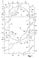
- a sheet 10 in particular of cardboard or the like, intended for producing the body of an assembly according to the invention.
- the sheet may be corrugated but may also be of cardboard.
- the sheet 10 has four faces 20, 30, 40 and 50, of substantially rectangular shape, intended to form respectively the bottom, the large side faces and the upper face of the box, the faces being successively interconnected by their larger edges .
- the face 20 intended to form the bottom of the box is delimited by four edges 21, 22, 23 and 24.
- the two large edges 21 and 22 are parallel to each other and are respectively connected to two lateral uprights 30 and 40 intended to form the two large side faces of the box.
- the two small edges 23 and 24, respectively perpendicular to the edges 21 and 22, are connected to flaps 25 and 26, substantially rectangular, which are intended to form part of the small side faces of the body, also called rear face 80 and face before 90.
- the edges 23 and 24 constitute fold lines.
- the flap 25, corresponding to the rear of the box, has a free edge 27, substantially parallel to the edge 23 which connects it to the face 20.
- An indentation 29 of semicircular shape, is formed substantially in the middle of the free edge 27 As will be seen in detail in the following description, this notch forms an access opening to introduce one or more fingers to open the box.
- the flap 26, corresponding to the front of the body, also has a free edge 28, substantially parallel to the edge 24 which connects to the face 20.
- the free edge 28 is this rectilinear.
- a notch 29 'of semicircular shape may be formed in the flap 26, from the edge 24 and substantially in its middle.
- the bottom 20 is connected, on one side, to the lateral upright 30 by the edge 21 common to these two faces.
- the lateral upright 30 is further delimited by three other edges 31, 32 and 33.
- the edge 31 corresponding to the rear edge is connected to a flap 34 of substantially rectangular shape, and constitutes a fold line.
- the flap 34 has a pre-cut line 37 formed at half of the flap, and extending over the entire height of the flap. This line 37 separates the flap into two parts, a lower part 34b and an upper part 34a.
- the precut line 37 is cut along the entire length of the flap except at a point 37a located at a distance from the free edge of the flap 34, but close enough to the edge to hold the flap and to be able to be detached with enough force.
- edge 32 corresponding to the front edge is also connected to a flap 35 of substantially rectangular shape, and is a fold line.
- edge 33 parallel to the edge 21 is connected to a tongue 36 of substantially rectangular shape.
- the tongue is used for fixing the lateral upright 30 on the upper face 50 on which it is for example glued or fixed by any other means.
- An opening 38 in the form of a semicircle is formed in the tongue from the edge 33, substantially in the middle. This opening 38 also serves, as will be seen in detail in the following description, access to introduce one or more fingers to open the box.
- the bottom 20 is connected, on a second side, to a lateral upright 40 by the edge 22 common to these two faces.
- the lateral upright 40 is further delimited by three other edges 41, 42 and 43.
- the edge 42 corresponding to the rear edge is connected to a rear flap 44 of substantially rectangular shape, and constitutes a fold line.
- the flap 44 has a pre-cut line 46 formed in the half of the flap, and extending over the entire height of the flap. This line separates the flap into two parts, a lower part 44a and an upper part 44b.
- the precut line 46 is cut along the entire length of the flap except at a point 46a located at a distance from the free edge of the flap 44, but close enough to the edge to hold the flap and to be able to be detached with sufficient force .
- edge 43 corresponding to the front edge is also connected to a front flap 45 of substantially rectangular shape, and constitutes a fold line.
- edge 41 parallel to the edge 22 is connected to the face 50 intended to form the upper face of the body.
- the face 50 intended to form the upper face of the box is delimited by the edge 41 common with the face 40 and three other edges 51, 52 and 53.
- the two large edges 41 and 53 are parallel to each other, the edge 53 being free in the example shown.
- the two small edges 51 and 52 respectively perpendicular to the edges 41 and 53, are connected to flaps 54 and 55, substantially rectangular, which are intended to form part of the front and rear faces of the body.
- the edges 51 and 52 constitute fold lines.
- the face 50 has two openings 56 and 57. These openings 56 and 57 are not connected by a line of weakness extending through the upper face.
- a first opening 56 is contiguous to the lateral face 40 and formed along the edge 41, substantially in the middle of this edge. According to the illustrated example, the opening 56 is delimited by a semicircle formed in the face 50, and by the upper edge of the face 40, rounded as will be seen in the following description.
- the second opening 57 is formed by a notch in the form of a semicircle formed substantially in the middle of the free edge 53.
- the second opening 57 of the upper face 50 is provided to be superimposed with the opening 38 formed in the tongue 36, when the tongue is fixed to the upper face 50 when the body is assembled. These two openings therefore advantageously have substantially the same shape.
- the flaps 25 and 54 are intended to form the rear face 80 of the box and the flaps 26 and 55 are intended to form the front face 90 of the box.
- All the flaps and the tongue of the body have a substantially rectangular shape, namely a slightly trapezoidal shape to leave a play between the different faces and facilitate the mechanization of the formatting of the body.
- a line of weakness extends over the entire periphery of the body.
- this line of least resistance consists of pre-cuts provided on the periphery of the box which separates the upper part of the box from the lower part so as to form a display for the objects contained in the box.
- the line is cut, in the entire thickness of the carton, according to dashed lines.
- the line of least resistance may comprise a cut half-flesh, namely on only part of the thickness of the cardboard.
- the mid-cut may extend continuously over the entire length of the line of weakness or in dashed lines. We can also alternate the different types of cutting in the same line of least resistance.
- a precut 60 is formed in each lateral upright 30 and 40, symmetrically, a portion 60a being formed in the lateral upright 30 and a portion 60b being formed in the lateral upright 40.
- the amount lateral 40 will be described in detail, the lateral amount 30 being symmetrical with respect to the median plane of the body.
- a portion 60b of the pre-cut 60 formed in the lateral upright 40 separates it into two parts, a lower part 40a intended to form part of the display and a top 40b.
- the precut 60b extends along a curved line along the entire length of the lateral upright 40 between the two adjacent lateral faces, namely the front face 90 and the rear face 80.
- the precut line 60b extends from a first end 63b located at the rear edge 42 of the face, from the middle of this edge where it joins the pre-cut line 46 of the flap 44, to a second end 62b located at the front edge 43 of the face, to the end of this edge 43, where it joins the edge 22 of the bottom.
- This rounded precut line 60b passes through a vertex 61b confused with the edge 41 of the lateral upright 40, substantially in the middle thereof.
- the top 61 b of the rounded precut line is adjacent to the opening 57 formed in the upper face 50.
- the position of the top 61b of the precut on an axis perpendicular to the plane of the bottom, namely on an axis parallel to the edges 42 or 43, is separated from the position of the lowest point 62b by a distance h corresponding to the entire height of the lateral upright 40.
- the position of the vertex 61b on the axis is separated from the position of the first end 63b of the line d about half the height of the amount.
- the precut line 60b therefore has a shape very far from a line parallel to the edges 22 and 41 of the lateral upright 40 so that there is little risk that the lateral upright 40 will bend along the line 60b when of the shaping of the box and in particular during the folding of the edges 22 and 41.
- the length of the pre-cut line is not the same on each side of the top.
- the line 60b is longer between the vertex 61b and the second end 62b than between the vertex 61b and the first end 63b.
- the line 60b disengages more rapidly to the first end 63b than to the second end 62b.
- a creasing 70b is formed between the top 61a and the first end 63a to force the lateral upright 40 to bend along this creasing when the separation of the pre-cut 60b.
- This creasing is rectilinear and is provided on the surface intended to be inside the body when it is assembled so as not to harm the aesthetics of the body. It is preferably made by a line of reduced thickness of the lateral amount.
- All edges of the faces defining fold lines may have a precut to facilitate the folding operation during the shaping of the body.
- the edge 24 separating the bottom 20 of the front flap 26 is pre-cut.
- the assembly of the sheet 10 intended to form the box can be performed in the following manner, which will now be described.
- the box is represented assembled and put in volume.
- the volume can be automated.
- the sheet of the box is first laid flat in a magazine.
- the face 20 forming the bottom of the box is held by suction and the lateral uprights 30, 40 and the flaps 34, 35, 44 and 45 are raised by folding folding lines 21, 22, 31, 32, 42 and 43.
- O objects are available, for example identical on the face 20 forming the bottom, preferably in an orderly manner, for example in rows.
- Objects O are for example constituted by devices for packaging a product, especially a cosmetic product, for example pots or other objects, possibly themselves in boxes. The storage steps of the objects O can be performed automatically.
- the tongue 36 is then folded along the fold line 33 and a line of glue is placed on the top of the tongue. Folding the upper face 50, along the fold line 41, is fixed on the tongue.
- Glue lines are deposited on the flaps 25, 54, 26 and 55 in order to close the rear and the front of the body.
- the back of the box is closed by folding the flaps 25 and 54 along the lines 23 and 51, which are glued to the flaps 34 and 44 so as to form the rear face 80 shown figure 2 .
- the front of the box is closed by folding the flaps 26 and 55 along the lines 24 and 52, which are glued on the flaps 35 and 45 so as to form the front face 90 shown figure 3 .
- the precut lines 60a and 60b do not tend to break because of their rounded shape which makes them more resistant since a fold is only in a straight line and not in a curved line.
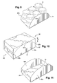
- the assembled case is illustrated at figure 5 .
- the user opens the box by removing the parts of the lateral uprights delimited by the precut lines 60a and 60b.
- the user introduces one or more fingers in the openings 56 and 57 formed in the upper face of the box and spreads the lower parts 30a and 40a of the two lateral uprights 30 and 40 of the rest of the box, in a movement perpendicular to the face.
- Such movement leads to shear stresses at the lines of least resistance, which improves sharpness at the edge where the line of weakness has been broken.
- the two parts 30a and 40a of the lateral uprights are spaced in opposite directions.
- the precut line is sheared without the risk of tearing through the perpendicular movement that allows to separate the two parts that separate by deviating orthogonally to the initial plane of the side face.
- the portions 60a and 60b of the precut line 60 do not have the same length on either side of their top, the lateral uprights tend to bend when the precut is completely detached from the shorter side while the The user always discards the amount in order to separate the other side of the line.
- the presence of grooves 70a and 70b forces the upright to bend "cleanly" along this creasing.
- openings 56 and 57 are preferably made close to the extremum of the curve that is continuously concave or convex relative to the bottom.
- Openings such as 56 and 57 may alternatively also be provided adjacent to the line of weakness within the side face. In this case, they are on the path of the line of least resistance. In fact each opening locally interrupts its line of least resistance.
- the user can lift the upper part of the body, by the rear part thereof as seen in the figure 7 .
- the user introduces one or more fingers in the opening 29 formed in the rear flap 25 and spreads the flap 54 from the rest of the box, again according to a movement perpendicular to the rear face.
- the upper part 34a and 44a of the flaps 34 and 44 being glued to the flap 54, these two parts tend to follow the movement of the flap 54 which will cause the proper break points of attachment 37a and 46a.
- the attachment points 37a and 46a being located at a distance from the opening 29, this will facilitate the opening of this part since the uncoupling is already initiated.
- the position of the opening allows to enter the flap 54 in an area near the attachment points.
- the upper rear portion is thus disengaged from the lower rear portion since the rupture lines 37 and 46 respectively join the rupture lines 60a and 60b of the lateral uprights.
- the illustrated display is thus obtained figure 9 where the O objects are present.
- the display is thus formed by the bottom 20 of the box, the lower parts 30a and 40a of the lateral uprights and by the rear flap 25.
- the invention is not limited to the example just described.
- the shape of the display can be modified and adapted for example to the nature of the objects and / or the marketing environment.
- the top 61 b of the pre-cut line may be located at a distance from the upper face 50, the opening 56 then being formed not in the face 50 but in the lateral upright 40.
- the top 61 b of the precut line may be located closer to the front face 90 than to the rear face 80 or vice versa, plus near the rear face 80 than the front face 90.
- the precut line may stop halfway up the side edge 43 at its second end 62b.
- the curvature of the pre-cut line is then the same on each side of the top 61 b.
- the front face 90 can then dissociate in two parts in the same manner as the rear face 80 so as to obtain the display shown in FIG. figure 11 .
- This display is then constituted by the bottom 20 of the box, the lower parts 30a and 40a of the lateral uprights, by the rear flap 25 and the front flap 26.
- the pre-cut line 60b may comprise at least one rectilinear portion instead of being curved.
- the precut line 160b extends from the upper face 150 and joins the adjoining side face 190 by a continuously concave path to the upper face.
- the front face remains the same, with an opening such as 29 to facilitate the breaking of attachment points such as 37a and 46a.
- the lowest point is in this case close to the bottom.
- a through opening 156, 157 respectively is formed at the lowest point, in the precut line 160b, respectively 160a, so as to allow the introduction of one or more fingers to allow traction towards the top of the portion that belongs to a top, to detach, the body.
- the variant represented in Figure 13 represents a precut line generally following the path of a curve C convexly convex to the upper face, but in which the precut line is made sawtooth, repeatedly throughout the path.
- the amplitude "a" of the teeth of saw along the path is always less than 1.5 centimeters, and preferably less than 0.5 centimeters.
- the width "I" of the repeated pattern is less than 30% and preferably less than 10%, or better still less than 1%, of the length of the edge of the side face with the bottom.
- a crate comprising such a precut line is the subject of the present invention.
- the pre-cut line provided for figure 14 provides two inflection points 98 and 99 delimiting a portion 97 of the concave precut line to the upper face, as opposed to the overall convexity of the path C of the precut line relative to this same upper face.
- the distance "g" between the highest point and the lowest point of this portion delimited between points 98 and 99 is less than 10% of the height "h" of the precut line.
- a crate comprising such a precut line is the subject of the present invention.
- the Figures 13 and 14 show examples of continuously convex curves towards the upper face including microvariations of their path.
Landscapes
- Engineering & Computer Science (AREA)
- Mechanical Engineering (AREA)
- Cartons (AREA)
Applications Claiming Priority (1)
| Application Number | Priority Date | Filing Date | Title |
|---|---|---|---|
| FR0754501A FR2914911B1 (fr) | 2007-04-16 | 2007-04-16 | Ensemble de transport et de presentation d'au moins un objet. |
Publications (1)
| Publication Number | Publication Date |
|---|---|
| EP1982930A1 true EP1982930A1 (de) | 2008-10-22 |
Family
ID=38751978
Family Applications (1)
| Application Number | Title | Priority Date | Filing Date |
|---|---|---|---|
| EP08154191A Withdrawn EP1982930A1 (de) | 2007-04-16 | 2008-04-08 | Transport- und Präsentationskasten für Gegenstände |
Country Status (2)
| Country | Link |
|---|---|
| EP (1) | EP1982930A1 (de) |
| FR (1) | FR2914911B1 (de) |
Citations (8)
| Publication number | Priority date | Publication date | Assignee | Title |
|---|---|---|---|---|
| DE8812979U1 (de) * | 1988-03-19 | 1988-12-08 | Henkel KGaA, 4000 Düsseldorf | Display-Versandfaltschachtel |
| US5480091A (en) * | 1995-05-11 | 1996-01-02 | The Mead Corporation | Stress-relieving arrangement for carton handles |
| JPH0853127A (ja) * | 1994-08-10 | 1996-02-27 | Asahi Breweries Ltd | 包装用箱 |
| JP2000159221A (ja) * | 1998-11-25 | 2000-06-13 | Kanebo Ltd | 一個箱 |
| JP2002068174A (ja) * | 2000-08-25 | 2002-03-08 | Toppan Printing Co Ltd | 開封が容易な集積箱を兼ねる包装用箱 |
| GB2383792A (en) | 2001-11-12 | 2003-07-09 | Ds Smith | Packaging cartons and blanks therefor |
| FR2843733A1 (fr) | 2002-08-23 | 2004-02-27 | Papeteries D Espaly | Emballage en carton ou en matiere plastique realise en deux parties |
| WO2007038748A1 (en) | 2005-09-28 | 2007-04-05 | Meadwestvaco Packaging Systems Llc | Carton with opening access feature |
-
2007
- 2007-04-16 FR FR0754501A patent/FR2914911B1/fr not_active Expired - Fee Related
-
2008
- 2008-04-08 EP EP08154191A patent/EP1982930A1/de not_active Withdrawn
Patent Citations (8)
| Publication number | Priority date | Publication date | Assignee | Title |
|---|---|---|---|---|
| DE8812979U1 (de) * | 1988-03-19 | 1988-12-08 | Henkel KGaA, 4000 Düsseldorf | Display-Versandfaltschachtel |
| JPH0853127A (ja) * | 1994-08-10 | 1996-02-27 | Asahi Breweries Ltd | 包装用箱 |
| US5480091A (en) * | 1995-05-11 | 1996-01-02 | The Mead Corporation | Stress-relieving arrangement for carton handles |
| JP2000159221A (ja) * | 1998-11-25 | 2000-06-13 | Kanebo Ltd | 一個箱 |
| JP2002068174A (ja) * | 2000-08-25 | 2002-03-08 | Toppan Printing Co Ltd | 開封が容易な集積箱を兼ねる包装用箱 |
| GB2383792A (en) | 2001-11-12 | 2003-07-09 | Ds Smith | Packaging cartons and blanks therefor |
| FR2843733A1 (fr) | 2002-08-23 | 2004-02-27 | Papeteries D Espaly | Emballage en carton ou en matiere plastique realise en deux parties |
| WO2007038748A1 (en) | 2005-09-28 | 2007-04-05 | Meadwestvaco Packaging Systems Llc | Carton with opening access feature |
Also Published As
| Publication number | Publication date |
|---|---|
| FR2914911A1 (fr) | 2008-10-17 |
| FR2914911B1 (fr) | 2011-12-02 |
Similar Documents
| Publication | Publication Date | Title |
|---|---|---|
| EP2007635B1 (de) | Schauschachtel mit stülpdeckel | |
| EP2259972B1 (de) | Kartonvorformensatz, schachtel und verfahren zur herstellung einer schachtel mit solchen vorformen | |
| EP1919782B1 (de) | Wellpappenschachtel mit durchbrochenen klappen und anordnung von zuschnitten, um diese zu erhalten | |
| EP0028995A1 (de) | Verpackung für pharmazeutische Ampullen oder dgl. | |
| CA2370696C (fr) | Caisse, ensemble de decoupes, procede d'ouverture d'une caisse, et procede et machine pour la fabrication d'une telle caisse | |
| EP3681809B1 (de) | Verpackung mit einer schale, hülse und manipulationssicheres element für die verpackung | |
| FR2799732A1 (fr) | Emballage en carton ou matiere similaire permettant d'extraire aisement son contenu | |
| WO1998001351A1 (fr) | Flan pour la realisation d'un emballage a couvercle emboitable | |
| EP1963197A1 (de) | Artikelverpackung mit einer teilweise abdeckenden seitenwand und einer das gesamte paket umhüllenden folie | |
| EP1982930A1 (de) | Transport- und Präsentationskasten für Gegenstände | |
| BE1006229A6 (fr) | Unite d'emballage remplie de lampes electriques emballees. | |
| EP1584565B1 (de) | Verpackung für einen Gegenstand | |
| EP3144238B1 (de) | Verpackung und zuschnitt für eine verpackung mit einer verbesserten öffnungsvorrichtung | |
| EP1615828A2 (de) | Präsentationspappschachtel mit offener stirnwand | |
| FR2683207A1 (fr) | Emballage de transport et de distribution. | |
| EP3530583B1 (de) | Zuschnitt einer komprimierbaren faltschachtel und komprimierbare faltschachtel | |
| EP1736414B1 (de) | Einheit zum Transport und zur Präsentation mindestens eines Objekts, Verpackungsverfahren mittels einer solchen Einheit und Öffnungsverfahren | |
| FR3077276A1 (fr) | Emballage de type pret a vendre realise en deux elements dont les fonds sont superposes. | |
| FR3021632A3 (fr) | Boite pliante | |
| FR2802179A1 (fr) | Flan et caisse d'emballage a paroi arrachable | |
| FR2878828A1 (fr) | Emballage en un materiau semi-rigide, comprenant deux parties assemblables, dont l'une coiffe l'autre, a systeme d'ouverture perfectionne | |
| EP2662298B1 (de) | Zwischenvorrichtung für Verpackung | |
| FR2804659A1 (fr) | Perfectionnements aux emballages gerbables en un materiau semi-rigide, dont une paroi laterale comporte une echancrure laissant apparaitre les objets conditionnes | |
| EP0541762A1 (de) | Verpackung bestehend aus einem flexibelen innenbeutel und einer steifen umhuellung and verfahren zur herstellung derselben | |
| BE1001359A6 (fr) | Recipient empilable, flan pour la fabrication d'un tel recipient et presentoir forme de tels recipients empiles. |
Legal Events
| Date | Code | Title | Description |
|---|---|---|---|
| PUAI | Public reference made under article 153(3) epc to a published international application that has entered the european phase |
Free format text: ORIGINAL CODE: 0009012 |
|
| AK | Designated contracting states |
Kind code of ref document: A1 Designated state(s): AT BE BG CH CY CZ DE DK EE ES FI FR GB GR HR HU IE IS IT LI LT LU LV MC MT NL NO PL PT RO SE SI SK TR |
|
| AX | Request for extension of the european patent |
Extension state: AL BA MK RS |
|
| 17P | Request for examination filed |
Effective date: 20090422 |
|
| 17Q | First examination report despatched |
Effective date: 20090525 |
|
| AKX | Designation fees paid |
Designated state(s): AT BE BG CH CY CZ DE DK EE ES FI FR GB GR HR HU IE IS IT LI LT LU LV MC MT NL NO PL PT RO SE SI SK TR |
|
| STAA | Information on the status of an ep patent application or granted ep patent |
Free format text: STATUS: THE APPLICATION IS DEEMED TO BE WITHDRAWN |
|
| 18D | Application deemed to be withdrawn |
Effective date: 20120313 |