EP1982930A1 - Box for transporting and displaying objects - Google Patents
Box for transporting and displaying objects Download PDFInfo
- Publication number
- EP1982930A1 EP1982930A1 EP08154191A EP08154191A EP1982930A1 EP 1982930 A1 EP1982930 A1 EP 1982930A1 EP 08154191 A EP08154191 A EP 08154191A EP 08154191 A EP08154191 A EP 08154191A EP 1982930 A1 EP1982930 A1 EP 1982930A1
- Authority
- EP
- European Patent Office
- Prior art keywords
- line
- face
- resistance
- box
- edge
- Prior art date
- Legal status (The legal status is an assumption and is not a legal conclusion. Google has not performed a legal analysis and makes no representation as to the accuracy of the status listed.)
- Withdrawn
Links
Images


Classifications
-
- B—PERFORMING OPERATIONS; TRANSPORTING
- B65—CONVEYING; PACKING; STORING; HANDLING THIN OR FILAMENTARY MATERIAL
- B65D—CONTAINERS FOR STORAGE OR TRANSPORT OF ARTICLES OR MATERIALS, e.g. BAGS, BARRELS, BOTTLES, BOXES, CANS, CARTONS, CRATES, DRUMS, JARS, TANKS, HOPPERS, FORWARDING CONTAINERS; ACCESSORIES, CLOSURES, OR FITTINGS THEREFOR; PACKAGING ELEMENTS; PACKAGES
- B65D71/00—Bundles of articles held together by packaging elements for convenience of storage or transport, e.g. portable segregating carrier for plural receptacles such as beer cans or pop bottles; Bales of material
- B65D71/06—Packaging elements holding or encircling completely or almost completely the bundle of articles, e.g. wrappers
- B65D71/12—Packaging elements holding or encircling completely or almost completely the bundle of articles, e.g. wrappers the packaging elements, e.g. wrappers being formed by folding a single blank
- B65D71/36—Packaging elements holding or encircling completely or almost completely the bundle of articles, e.g. wrappers the packaging elements, e.g. wrappers being formed by folding a single blank having a tubular shape, e.g. tubular wrappers, with end walls
-
- B—PERFORMING OPERATIONS; TRANSPORTING
- B65—CONVEYING; PACKING; STORING; HANDLING THIN OR FILAMENTARY MATERIAL
- B65D—CONTAINERS FOR STORAGE OR TRANSPORT OF ARTICLES OR MATERIALS, e.g. BAGS, BARRELS, BOTTLES, BOXES, CANS, CARTONS, CRATES, DRUMS, JARS, TANKS, HOPPERS, FORWARDING CONTAINERS; ACCESSORIES, CLOSURES, OR FITTINGS THEREFOR; PACKAGING ELEMENTS; PACKAGES
- B65D5/00—Rigid or semi-rigid containers of polygonal cross-section, e.g. boxes, cartons or trays, formed by folding or erecting one or more blanks made of paper
- B65D5/42—Details of containers or of foldable or erectable container blanks
- B65D5/44—Integral, inserted or attached portions forming internal or external fittings
- B65D5/52—External stands or display elements for contents
-
- B—PERFORMING OPERATIONS; TRANSPORTING
- B65—CONVEYING; PACKING; STORING; HANDLING THIN OR FILAMENTARY MATERIAL
- B65D—CONTAINERS FOR STORAGE OR TRANSPORT OF ARTICLES OR MATERIALS, e.g. BAGS, BARRELS, BOTTLES, BOXES, CANS, CARTONS, CRATES, DRUMS, JARS, TANKS, HOPPERS, FORWARDING CONTAINERS; ACCESSORIES, CLOSURES, OR FITTINGS THEREFOR; PACKAGING ELEMENTS; PACKAGES
- B65D2571/00—Bundles of articles held together by packaging elements for convenience of storage or transport, e.g. portable segregating carrier for plural receptacles such as beer cans, pop bottles; Bales of material
- B65D2571/00123—Bundling wrappers or trays
- B65D2571/00129—Wrapper locking means
- B65D2571/00135—Wrapper locking means integral with the wrapper
- B65D2571/00141—Wrapper locking means integral with the wrapper glued
-
- B—PERFORMING OPERATIONS; TRANSPORTING
- B65—CONVEYING; PACKING; STORING; HANDLING THIN OR FILAMENTARY MATERIAL
- B65D—CONTAINERS FOR STORAGE OR TRANSPORT OF ARTICLES OR MATERIALS, e.g. BAGS, BARRELS, BOTTLES, BOXES, CANS, CARTONS, CRATES, DRUMS, JARS, TANKS, HOPPERS, FORWARDING CONTAINERS; ACCESSORIES, CLOSURES, OR FITTINGS THEREFOR; PACKAGING ELEMENTS; PACKAGES
- B65D2571/00—Bundles of articles held together by packaging elements for convenience of storage or transport, e.g. portable segregating carrier for plural receptacles such as beer cans, pop bottles; Bales of material
- B65D2571/00123—Bundling wrappers or trays
- B65D2571/00555—Wrapper opening devices
- B65D2571/00561—Lines of weakness
- B65D2571/00574—Lines of weakness whereby contents can still be carried after the line has been torn
-
- B—PERFORMING OPERATIONS; TRANSPORTING
- B65—CONVEYING; PACKING; STORING; HANDLING THIN OR FILAMENTARY MATERIAL
- B65D—CONTAINERS FOR STORAGE OR TRANSPORT OF ARTICLES OR MATERIALS, e.g. BAGS, BARRELS, BOTTLES, BOXES, CANS, CARTONS, CRATES, DRUMS, JARS, TANKS, HOPPERS, FORWARDING CONTAINERS; ACCESSORIES, CLOSURES, OR FITTINGS THEREFOR; PACKAGING ELEMENTS; PACKAGES
- B65D2571/00—Bundles of articles held together by packaging elements for convenience of storage or transport, e.g. portable segregating carrier for plural receptacles such as beer cans, pop bottles; Bales of material
- B65D2571/00123—Bundling wrappers or trays
- B65D2571/00648—Elements used to form the wrapper
- B65D2571/00654—Blanks
- B65D2571/0066—Blanks formed from one single sheet
-
- B—PERFORMING OPERATIONS; TRANSPORTING
- B65—CONVEYING; PACKING; STORING; HANDLING THIN OR FILAMENTARY MATERIAL
- B65D—CONTAINERS FOR STORAGE OR TRANSPORT OF ARTICLES OR MATERIALS, e.g. BAGS, BARRELS, BOTTLES, BOXES, CANS, CARTONS, CRATES, DRUMS, JARS, TANKS, HOPPERS, FORWARDING CONTAINERS; ACCESSORIES, CLOSURES, OR FITTINGS THEREFOR; PACKAGING ELEMENTS; PACKAGES
- B65D2571/00—Bundles of articles held together by packaging elements for convenience of storage or transport, e.g. portable segregating carrier for plural receptacles such as beer cans, pop bottles; Bales of material
- B65D2571/00123—Bundling wrappers or trays
- B65D2571/00709—Shape of the formed wrapper, i.e. shape of each formed element if the wrapper is made from more than one element
- B65D2571/00722—Shape of the formed wrapper, i.e. shape of each formed element if the wrapper is made from more than one element tubular with end walls, e.g. walls not extending on the whole end surface
- B65D2571/00728—Shape of the formed wrapper, i.e. shape of each formed element if the wrapper is made from more than one element tubular with end walls, e.g. walls not extending on the whole end surface the end walls being closed by gluing
Definitions
- the present invention relates to a crate for the transport and presentation of at least one object.
- the invention relates to a box designed to be shaped around a plurality of objects, via a wrap around cartoner, the crate formed around the objects being obtained from a flat pre-cut sheet. .
- FR 2 843 733 a transport case that can be transformed into a display unit using a precut system extending all around the box.
- the box has four side faces, two large and two small, a pre-cut line extending around the entire periphery of the box being formed in each of the faces.
- an insert is provided inside the body, in the form of double wall extending over the entire height of at least two side faces of the box so as to stiffen them.
- a disadvantage of this packaging is that the shape of the pre-cuts on the periphery of the box is not suitable for crates shaped by folding the large side faces relative to the bottom, since the pre-cuts formed in these faces are slightly inclined relative to the edge to be folded. They are indeed close to being parallel to these edges so that during shaping, the face will tend to bend at the precut instead of bending at the edge separating it from the bottom.
- this type of box can not be used to become a transport crate shaped around objects to contain. Indeed, in the case where these objects are not parallelepipedic, it is impossible to train them in piles. Now the bottom of such a box is formed by flaps. It is therefore necessary to format the box, and in particular its bottom, before being able to fill it with objects to contain.
- Document is known GB-2383792 a box adapted to be shaped around a group of parallelepipedic objects.
- Document is also known WO-07/038748 a box with multiple pre-cut lines to allow access to the contents of the box.
- the tear of the precuts is performed in two stages, a first to partially open an upper face and a second to completely clear this upper face.
- the increase in the number of steps increases the number of unit waste resulting from the opening of such a box.
- the invention aims to remedy all or part of these disadvantages and to meet all or part of the needs expressed above.
- any line of least resistance By extending mainly along an edge of this side face with the bottom is meant any line of least resistance, except those whose path within the side face on which they are formed allow to connect the upper face to the bottom, and except those that do not open at both ends at at least one edge of the side face in which they are formed.
- the lines of least resistance that go from a second side face adjacent to a third side face adjoining, or which go from a side face adjacent to one of the bottom or the upper face, or which go from the upper side on the upper face, or which go from the bottom to the bottom, are lines of least resistance extending mainly along an edge of this side face with the bottom.
- curve is meant any continuously curved path of the line of least resistance, and any path having random or repetitive path microvariations. These microvariations may be such that they do not modify the tear at the level of the line of least resistance and make it possible to guarantee a generally concave or continuously convex general appearance at the edge resulting from the breaking of the line of least resistance. These microvariations may have a succession of concavities and convexities, the latter being of an amplitude less than 30%, and preferably less than 10%, of the amplitude of the concavity or of the general convexity observed for the whole of the line of least resistance.
- the line of least resistance being formed in a lateral face, over its entire length, through a maximum and a minimum which are relatively spaced apart from each other, it is possible to make a line of least resistance relatively inclined with respect to edges of the face in which it is arranged.
- a line of least resistance relatively inclined with respect to edges of the face in which it is arranged.
- the highest point of the line of least resistance may be located at an upper edge of the first side face, adjacent to the upper face. We can easily start the separation of the upper part of the face from the lower part from the highest point of the line of least resistance that can easily be grasped.
- the highest point of the line of weakness of the first side face may be located midway between the second and third side faces. By centering the highest part of the line of least resistance by which we will initiate the separation, it limits the efforts required to separate the two parts of the first side face along the entire length of the line of weakness.
- the lowest point of the line of weakness can be located at a lower edge of the first side face, adjacent to the bottom. This maximizes the slope of the line of least resistance which extends over a large part of the height of the first lateral face so as to make the line of least resistance as oblique as possible edges that delimit the first side face.
- the lowest point of the line of least resistance may be located at an edge adjacent to the second or third side face. This makes it possible to connect the line of least resistance of this first lateral face to a line of least resistance formed on the lower edge of the second or third adjacent lateral face.
- the edge of the second or third lateral face separating it from the bottom is thus used to form a line of least resistance in this second or third lateral face. This avoids forming a line of least additional resistance in this face.
- the highest point of the line of weakness may be adjacent to an opening.
- This opening allows access to the interior of the body for the user who can grasp the part of the first face to separate from the rest of the first face.
- the opening may be formed in the upper face of the body. This allows to separate the part of the first side face in a movement perpendicular to the face, ergonomically.
- the opening is very visible which encourages the user to introduce the fingers.
- the line of least resistance may be curved.
- the line of least resistance may in particular be convex towards the upper face. This optimizes the resistance of the face, since it does not tend to bend along the curved line during the shaping of the body, while facilitating the separation according to this curved line.
- the formatting of the box can be done at a high rate.
- the line of least resistance may comprise at least one pre-cut, including a cut line, over the entire thickness of the face, according to dotted lines.
- the dots may be longer or shorter, their length may vary along the same line of least resistance.
- the line of least resistance may also include a cut half-flesh, namely on only part of the thickness of the face. Such a cut is particularly suitable for crates made of cardboard.
- the mid-cut may extend continuously over the entire length of the line of weakness or in dashed lines. We can also alternate the different types of cutting in the same line of least resistance.
- the first lateral face having a line of least resistance may also comprise a creasing, that is to say a groove intended to form a fold line, intended to force the first face to bend along this creasing when cutting the line of least resistance. It is thus possible, if necessary, the face to deform without tearing during the separation of the two parts of the face.
- Creasing may be formed on the inner surface of the first side face to orient the folding. Being on the inner surface of the face, the creasing does not affect the aesthetics of the lower part of the box to form the display of which it is part.
- the line of least resistance can cross a fourth lateral face opposite to the first.
- the first and fourth side faces may be symmetrical. The gesture necessary to open the box, is thus simplified.
- the box may comprise a cardboard or the like, including a corrugated cardboard or flat.
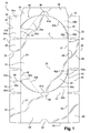
- a sheet 10 in particular of cardboard or the like, intended for producing the body of an assembly according to the invention.
- the sheet may be corrugated but may also be of cardboard.
- the sheet 10 has four faces 20, 30, 40 and 50, of substantially rectangular shape, intended to form respectively the bottom, the large side faces and the upper face of the box, the faces being successively interconnected by their larger edges .
- the face 20 intended to form the bottom of the box is delimited by four edges 21, 22, 23 and 24.
- the two large edges 21 and 22 are parallel to each other and are respectively connected to two lateral uprights 30 and 40 intended to form the two large side faces of the box.
- the two small edges 23 and 24, respectively perpendicular to the edges 21 and 22, are connected to flaps 25 and 26, substantially rectangular, which are intended to form part of the small side faces of the body, also called rear face 80 and face before 90.
- the edges 23 and 24 constitute fold lines.
- the flap 25, corresponding to the rear of the box, has a free edge 27, substantially parallel to the edge 23 which connects it to the face 20.
- An indentation 29 of semicircular shape, is formed substantially in the middle of the free edge 27 As will be seen in detail in the following description, this notch forms an access opening to introduce one or more fingers to open the box.
- the flap 26, corresponding to the front of the body, also has a free edge 28, substantially parallel to the edge 24 which connects to the face 20.
- the free edge 28 is this rectilinear.
- a notch 29 'of semicircular shape may be formed in the flap 26, from the edge 24 and substantially in its middle.
- the bottom 20 is connected, on one side, to the lateral upright 30 by the edge 21 common to these two faces.
- the lateral upright 30 is further delimited by three other edges 31, 32 and 33.
- the edge 31 corresponding to the rear edge is connected to a flap 34 of substantially rectangular shape, and constitutes a fold line.
- the flap 34 has a pre-cut line 37 formed at half of the flap, and extending over the entire height of the flap. This line 37 separates the flap into two parts, a lower part 34b and an upper part 34a.
- the precut line 37 is cut along the entire length of the flap except at a point 37a located at a distance from the free edge of the flap 34, but close enough to the edge to hold the flap and to be able to be detached with enough force.
- edge 32 corresponding to the front edge is also connected to a flap 35 of substantially rectangular shape, and is a fold line.
- edge 33 parallel to the edge 21 is connected to a tongue 36 of substantially rectangular shape.
- the tongue is used for fixing the lateral upright 30 on the upper face 50 on which it is for example glued or fixed by any other means.
- An opening 38 in the form of a semicircle is formed in the tongue from the edge 33, substantially in the middle. This opening 38 also serves, as will be seen in detail in the following description, access to introduce one or more fingers to open the box.
- the bottom 20 is connected, on a second side, to a lateral upright 40 by the edge 22 common to these two faces.
- the lateral upright 40 is further delimited by three other edges 41, 42 and 43.
- the edge 42 corresponding to the rear edge is connected to a rear flap 44 of substantially rectangular shape, and constitutes a fold line.
- the flap 44 has a pre-cut line 46 formed in the half of the flap, and extending over the entire height of the flap. This line separates the flap into two parts, a lower part 44a and an upper part 44b.
- the precut line 46 is cut along the entire length of the flap except at a point 46a located at a distance from the free edge of the flap 44, but close enough to the edge to hold the flap and to be able to be detached with sufficient force .
- edge 43 corresponding to the front edge is also connected to a front flap 45 of substantially rectangular shape, and constitutes a fold line.
- edge 41 parallel to the edge 22 is connected to the face 50 intended to form the upper face of the body.
- the face 50 intended to form the upper face of the box is delimited by the edge 41 common with the face 40 and three other edges 51, 52 and 53.
- the two large edges 41 and 53 are parallel to each other, the edge 53 being free in the example shown.
- the two small edges 51 and 52 respectively perpendicular to the edges 41 and 53, are connected to flaps 54 and 55, substantially rectangular, which are intended to form part of the front and rear faces of the body.
- the edges 51 and 52 constitute fold lines.
- the face 50 has two openings 56 and 57. These openings 56 and 57 are not connected by a line of weakness extending through the upper face.
- a first opening 56 is contiguous to the lateral face 40 and formed along the edge 41, substantially in the middle of this edge. According to the illustrated example, the opening 56 is delimited by a semicircle formed in the face 50, and by the upper edge of the face 40, rounded as will be seen in the following description.
- the second opening 57 is formed by a notch in the form of a semicircle formed substantially in the middle of the free edge 53.
- the second opening 57 of the upper face 50 is provided to be superimposed with the opening 38 formed in the tongue 36, when the tongue is fixed to the upper face 50 when the body is assembled. These two openings therefore advantageously have substantially the same shape.
- the flaps 25 and 54 are intended to form the rear face 80 of the box and the flaps 26 and 55 are intended to form the front face 90 of the box.
- All the flaps and the tongue of the body have a substantially rectangular shape, namely a slightly trapezoidal shape to leave a play between the different faces and facilitate the mechanization of the formatting of the body.
- a line of weakness extends over the entire periphery of the body.
- this line of least resistance consists of pre-cuts provided on the periphery of the box which separates the upper part of the box from the lower part so as to form a display for the objects contained in the box.
- the line is cut, in the entire thickness of the carton, according to dashed lines.
- the line of least resistance may comprise a cut half-flesh, namely on only part of the thickness of the cardboard.
- the mid-cut may extend continuously over the entire length of the line of weakness or in dashed lines. We can also alternate the different types of cutting in the same line of least resistance.
- a precut 60 is formed in each lateral upright 30 and 40, symmetrically, a portion 60a being formed in the lateral upright 30 and a portion 60b being formed in the lateral upright 40.
- the amount lateral 40 will be described in detail, the lateral amount 30 being symmetrical with respect to the median plane of the body.
- a portion 60b of the pre-cut 60 formed in the lateral upright 40 separates it into two parts, a lower part 40a intended to form part of the display and a top 40b.
- the precut 60b extends along a curved line along the entire length of the lateral upright 40 between the two adjacent lateral faces, namely the front face 90 and the rear face 80.
- the precut line 60b extends from a first end 63b located at the rear edge 42 of the face, from the middle of this edge where it joins the pre-cut line 46 of the flap 44, to a second end 62b located at the front edge 43 of the face, to the end of this edge 43, where it joins the edge 22 of the bottom.
- This rounded precut line 60b passes through a vertex 61b confused with the edge 41 of the lateral upright 40, substantially in the middle thereof.
- the top 61 b of the rounded precut line is adjacent to the opening 57 formed in the upper face 50.
- the position of the top 61b of the precut on an axis perpendicular to the plane of the bottom, namely on an axis parallel to the edges 42 or 43, is separated from the position of the lowest point 62b by a distance h corresponding to the entire height of the lateral upright 40.
- the position of the vertex 61b on the axis is separated from the position of the first end 63b of the line d about half the height of the amount.
- the precut line 60b therefore has a shape very far from a line parallel to the edges 22 and 41 of the lateral upright 40 so that there is little risk that the lateral upright 40 will bend along the line 60b when of the shaping of the box and in particular during the folding of the edges 22 and 41.
- the length of the pre-cut line is not the same on each side of the top.
- the line 60b is longer between the vertex 61b and the second end 62b than between the vertex 61b and the first end 63b.
- the line 60b disengages more rapidly to the first end 63b than to the second end 62b.
- a creasing 70b is formed between the top 61a and the first end 63a to force the lateral upright 40 to bend along this creasing when the separation of the pre-cut 60b.
- This creasing is rectilinear and is provided on the surface intended to be inside the body when it is assembled so as not to harm the aesthetics of the body. It is preferably made by a line of reduced thickness of the lateral amount.
- All edges of the faces defining fold lines may have a precut to facilitate the folding operation during the shaping of the body.
- the edge 24 separating the bottom 20 of the front flap 26 is pre-cut.
- the assembly of the sheet 10 intended to form the box can be performed in the following manner, which will now be described.
- the box is represented assembled and put in volume.
- the volume can be automated.
- the sheet of the box is first laid flat in a magazine.
- the face 20 forming the bottom of the box is held by suction and the lateral uprights 30, 40 and the flaps 34, 35, 44 and 45 are raised by folding folding lines 21, 22, 31, 32, 42 and 43.
- O objects are available, for example identical on the face 20 forming the bottom, preferably in an orderly manner, for example in rows.
- Objects O are for example constituted by devices for packaging a product, especially a cosmetic product, for example pots or other objects, possibly themselves in boxes. The storage steps of the objects O can be performed automatically.
- the tongue 36 is then folded along the fold line 33 and a line of glue is placed on the top of the tongue. Folding the upper face 50, along the fold line 41, is fixed on the tongue.
- Glue lines are deposited on the flaps 25, 54, 26 and 55 in order to close the rear and the front of the body.
- the back of the box is closed by folding the flaps 25 and 54 along the lines 23 and 51, which are glued to the flaps 34 and 44 so as to form the rear face 80 shown figure 2 .
- the front of the box is closed by folding the flaps 26 and 55 along the lines 24 and 52, which are glued on the flaps 35 and 45 so as to form the front face 90 shown figure 3 .
- the precut lines 60a and 60b do not tend to break because of their rounded shape which makes them more resistant since a fold is only in a straight line and not in a curved line.
- the assembled case is illustrated at figure 5 .
- the user opens the box by removing the parts of the lateral uprights delimited by the precut lines 60a and 60b.
- the user introduces one or more fingers in the openings 56 and 57 formed in the upper face of the box and spreads the lower parts 30a and 40a of the two lateral uprights 30 and 40 of the rest of the box, in a movement perpendicular to the face.
- Such movement leads to shear stresses at the lines of least resistance, which improves sharpness at the edge where the line of weakness has been broken.
- the two parts 30a and 40a of the lateral uprights are spaced in opposite directions.
- the precut line is sheared without the risk of tearing through the perpendicular movement that allows to separate the two parts that separate by deviating orthogonally to the initial plane of the side face.
- the portions 60a and 60b of the precut line 60 do not have the same length on either side of their top, the lateral uprights tend to bend when the precut is completely detached from the shorter side while the The user always discards the amount in order to separate the other side of the line.
- the presence of grooves 70a and 70b forces the upright to bend "cleanly" along this creasing.
- openings 56 and 57 are preferably made close to the extremum of the curve that is continuously concave or convex relative to the bottom.
- Openings such as 56 and 57 may alternatively also be provided adjacent to the line of weakness within the side face. In this case, they are on the path of the line of least resistance. In fact each opening locally interrupts its line of least resistance.
- the user can lift the upper part of the body, by the rear part thereof as seen in the figure 7 .
- the user introduces one or more fingers in the opening 29 formed in the rear flap 25 and spreads the flap 54 from the rest of the box, again according to a movement perpendicular to the rear face.
- the upper part 34a and 44a of the flaps 34 and 44 being glued to the flap 54, these two parts tend to follow the movement of the flap 54 which will cause the proper break points of attachment 37a and 46a.
- the attachment points 37a and 46a being located at a distance from the opening 29, this will facilitate the opening of this part since the uncoupling is already initiated.
- the position of the opening allows to enter the flap 54 in an area near the attachment points.
- the upper rear portion is thus disengaged from the lower rear portion since the rupture lines 37 and 46 respectively join the rupture lines 60a and 60b of the lateral uprights.
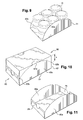
- the illustrated display is thus obtained figure 9 where the O objects are present.
- the display is thus formed by the bottom 20 of the box, the lower parts 30a and 40a of the lateral uprights and by the rear flap 25.
- the invention is not limited to the example just described.
- the shape of the display can be modified and adapted for example to the nature of the objects and / or the marketing environment.
- the top 61 b of the pre-cut line may be located at a distance from the upper face 50, the opening 56 then being formed not in the face 50 but in the lateral upright 40.
- the top 61 b of the precut line may be located closer to the front face 90 than to the rear face 80 or vice versa, plus near the rear face 80 than the front face 90.
- the precut line may stop halfway up the side edge 43 at its second end 62b.
- the curvature of the pre-cut line is then the same on each side of the top 61 b.
- the front face 90 can then dissociate in two parts in the same manner as the rear face 80 so as to obtain the display shown in FIG. figure 11 .
- This display is then constituted by the bottom 20 of the box, the lower parts 30a and 40a of the lateral uprights, by the rear flap 25 and the front flap 26.
- the pre-cut line 60b may comprise at least one rectilinear portion instead of being curved.
- the precut line 160b extends from the upper face 150 and joins the adjoining side face 190 by a continuously concave path to the upper face.
- the front face remains the same, with an opening such as 29 to facilitate the breaking of attachment points such as 37a and 46a.
- the lowest point is in this case close to the bottom.
- a through opening 156, 157 respectively is formed at the lowest point, in the precut line 160b, respectively 160a, so as to allow the introduction of one or more fingers to allow traction towards the top of the portion that belongs to a top, to detach, the body.
- the variant represented in Figure 13 represents a precut line generally following the path of a curve C convexly convex to the upper face, but in which the precut line is made sawtooth, repeatedly throughout the path.
- the amplitude "a" of the teeth of saw along the path is always less than 1.5 centimeters, and preferably less than 0.5 centimeters.
- the width "I" of the repeated pattern is less than 30% and preferably less than 10%, or better still less than 1%, of the length of the edge of the side face with the bottom.
- a crate comprising such a precut line is the subject of the present invention.
- the pre-cut line provided for figure 14 provides two inflection points 98 and 99 delimiting a portion 97 of the concave precut line to the upper face, as opposed to the overall convexity of the path C of the precut line relative to this same upper face.
- the distance "g" between the highest point and the lowest point of this portion delimited between points 98 and 99 is less than 10% of the height "h" of the precut line.
- a crate comprising such a precut line is the subject of the present invention.
- the Figures 13 and 14 show examples of continuously convex curves towards the upper face including microvariations of their path.
Landscapes
- Engineering & Computer Science (AREA)
- Mechanical Engineering (AREA)
- Cartons (AREA)
Abstract
La présente invention concerne une caisse destinée à être mise en forme autour d'une pluralité d'objets à transporter (O), comportant un fond (20) depuis lequel des objets sont destinés à être dressés, une face supérieure (50) et des faces latérales (30, 40, 80 et 90) reliant le fond à la face supérieure, une ligne de moindre résistance (60b) étant ménagée dans au moins une première face latérale (40) pour permettre de séparer une partie haute (40b) de cette face restant solidaire de la face supérieure d'une partie basse (40a) de cette face restant solidaire du fond, la ligne de moindre résistance s'étendant principalement le long d'un bord de cette face latérale avec le fond, selon une ligne , le long de son trajet, croît vers l'une de la face supérieure ou du fond puis qui décroît vers l'autre du fond ou de la face supérieure, la position du point le plus haut (61 b) de la ligne, selon un axe perpendiculaire au plan du fond, étant espacée de la position du point le plus bas (62b) selon cet axe, d'une distance (h) au moins égale à la moitié de la hauteur de la première face latérale, la ligne de moindre résistance étant une courbe continûment concave ou continûment convexe relativement à la face supérieure.The present invention relates to a box to be shaped around a plurality of objects to be transported (O), having a bottom (20) from which objects are intended to be erected, an upper face (50) and lateral faces (30, 40, 80 and 90) connecting the bottom to the upper face, a line of least resistance (60b) being formed in at least one first lateral face (40) to allow separation of an upper part (40b) of this face remaining integral with the upper face of a lower part (40a) of this face remaining integral with the bottom, the line of least resistance extending mainly along an edge of this side face with the bottom, along a line along its path, it increases towards one of the upper face or the bottom and then decreases towards the other of the bottom or the upper face, the position of the highest point (61 b) of the line, according to an axis perpendicular to the plane of the bottom, being spaced from the positio n from the lowest point (62b) along this axis, by a distance (h) at least equal to half the height of the first lateral face, the line of weakness being a continuously concave or continuously convex curve relative to the upper face.
Description
La présente invention concerne une caisse pour le transport et la présentation d'au moins un objet. En particulier, l'invention concerne une caisse prévue pour être mise en forme autour d'une pluralité d'objets, via une encartonneuse dite « wrap around », la caisse formée autour des objets étant obtenue à partir d'une feuille prédécoupée à plat.The present invention relates to a crate for the transport and presentation of at least one object. In particular, the invention relates to a box designed to be shaped around a plurality of objects, via a wrap around cartoner, the crate formed around the objects being obtained from a flat pre-cut sheet. .
Il existe un besoin pour bénéficier d'une caisse de transport qui puisse également servir à la présentation du ou des objets conditionnés.There is a need to benefit from a transport case which can also be used for the presentation of the conditioned object or objects.
Il existe encore un besoin pour faciliter l'automatisation des opérations d'emballage d'un ou plusieurs objets dans une caisse servant à la fois au transport et à la présentation de ce ou ces objets dans le rayon d'un magasin notamment.There is still a need to facilitate the automation of the packaging operations of one or more objects in a box for both the transport and the presentation of this or these objects in the radius of a particular store.
Il existe encore un besoin pour bénéficier d'une caisse compatible avec une mise en volume automatisée, capable de protéger efficacement le ou les objets conditionnés à l'intérieur tout en utilisant pour des raisons économiques et écologiques le moins de matière possible.There is still a need to benefit from a box compatible with an automated volume, able to effectively protect the object or objects packaged inside while using for economic and ecological reasons the least possible material.
Il existe un besoin pour une caisse destinée à être mise en forme autour d'une pluralité d'objets à transporter, et ultérieurement à présenter, qui permette l'automatisation de sa mise en forme.There is a need for a box to be shaped around a plurality of objects to be transported, and subsequently to present, which allows the automation of its formatting.
Il existe encore un besoin pour bénéficier d'une caisse réduisant les risques de mauvais pliage.There is still a need to benefit from a cash register that reduces the risk of misfolding.
Il existe enfin un besoin pour faciliter la mise en linéaire d'objets dans un magasin, en réduisant notamment les opérations de manutention des objets et surtout les gestes nécessaires à l'ouverture de la caisse. Il existe en effet un besoin pour faciliter une découpe propre et présentable des caisses destinées à rester sur des linéaires de commercialisation.Finally, there is a need to facilitate the placing of objects in a store, in particular by reducing the operations of handling objects and especially the actions necessary to open the box. There is indeed a need to facilitate a clean and presentable cutting of boxes intended to remain on the marketing shelf.
On connaît par la demande de brevet
Un inconvénient de cet emballage tient au fait que la forme des prédécoupes sur le pourtour de la caisse n'est pas adaptée à des caisses mises en forme en rabattant les grandes faces latérales par rapport au fond étant donné que les prédécoupes ménagées dans ces faces sont peu inclinées relativement au bord qui doit être plié. Elles sont en effet proches d'être parallèles à ces bords de sorte que lors de la mise en forme, la face aura tendance à se plier au niveau de la prédécoupe au lieu de se plier au niveau du bord la séparant du fond.A disadvantage of this packaging is that the shape of the pre-cuts on the periphery of the box is not suitable for crates shaped by folding the large side faces relative to the bottom, since the pre-cuts formed in these faces are slightly inclined relative to the edge to be folded. They are indeed close to being parallel to these edges so that during shaping, the face will tend to bend at the precut instead of bending at the edge separating it from the bottom.
En outre, la présence d'un insert pour renforcer la caisse ne facilite pas son ouverture. Pour séparer la partie supérieure de la caisse de la partie inférieure, il est en effet nécessaire de désolidariser deux à deux les parties hautes des deux grandes faces de leur partie basse, puis les parties hautes des deux petites faces de leur partie basse. Une fois que la partie supérieure est entièrement désolidarisée de la partie inférieure, l'utilisateur doit soulever la partie supérieure avec l'insert qui lui est solidaire de façon à l'écarter de la partie inférieure. La présence de l'insert complique ainsi la désolidarisation de la partie supérieure de la caisse de la partie inférieure pour former le présentoir et augmente aussi le coût de fabrication de la caisse.In addition, the presence of an insert to strengthen the body does not facilitate its opening. To separate the upper part of the box from the lower part, it is indeed necessary to separate two by two the upper parts of the two large faces of their lower part, then the upper parts of the two small faces of their lower part. Once the upper part is completely disengaged from the lower part, the user must lift the upper part with the insert which is secured to it away from the lower part. The presence of the insert thus complicates the separation of the upper part of the box from the lower part to form the display and also increases the manufacturing cost of the box.
De plus ce type de caisse ne peut pas être utilisé pour devenir une caisse de transport mise en forme autour d'objets à contenir. En effet, dans le cas où ces objets ne sont pas parallélépipédiques, il est impossible de les dresser en tas. Or le fond d'une telle caisse est formé par des rabats. Il est donc nécessaire de mettre en forme la caisse, et en particulier son fond, avant de pouvoir la remplir d'objets à contenir.In addition, this type of box can not be used to become a transport crate shaped around objects to contain. Indeed, in the case where these objects are not parallelepipedic, it is impossible to train them in piles. Now the bottom of such a box is formed by flaps. It is therefore necessary to format the box, and in particular its bottom, before being able to fill it with objects to contain.
On connaît du document
On connaît également du document
Il existe un besoin pour minimiser le nombre de déchets formés par l'ouverture d'une caisse de transport d'objets.There is a need to minimize the amount of waste formed by opening an object transport crate.
L'invention vise à remédier à tout ou partie de ces inconvénients et à répondre à tout ou partie des besoins exprimés plus haut.The invention aims to remedy all or part of these disadvantages and to meet all or part of the needs expressed above.
Elle y parvient grâce à une caisse, notamment en carton, destinée à être mise en forme autour d'une pluralité d'objets à transporter (O), comportant un fond (20) depuis lequel des objets sont destinés à être dressés, une face supérieure et des faces latérales reliant le fond à la face supérieure, une ligne de moindre résistance étant ménagée dans au moins une première face latérale pour permettre de séparer une partie haute de cette face restant solidaire de la face supérieure d'une partie basse de cette face restant solidaire du fond, la ligne de moindre résistance s'étendant principalement le long d'un bord de cette face latérale avec le fond, selon une ligne qui, le long de son trajet, croît vers l'une de la face supérieure ou du fond puis qui décroît vers l'autre du fond ou de la face supérieure, la position du point le plus haut (61 b) de la ligne, selon un axe perpendiculaire au plan du fond, étant espacée de la position du point le plus bas (62b) selon cet axe, d'une distance (h) au moins égale à la moitié de la hauteur de la première face latérale, la ligne de moindre résistance étant une courbe continûment concave ou continûment convexe relativement à la face supérieure.It achieves this through a box, in particular cardboard, intended to be shaped around a plurality of objects to be transported (O), having a bottom (20) from which objects are intended to be erected, one face upper and side faces connecting the bottom to the upper face, a line of least resistance being formed in at least a first side face to allow to separate an upper part of this face remaining secured to the upper face of a lower part of this with the face remaining attached to the bottom, the line of least resistance extending mainly along an edge of this side face with the bottom, along a line which, along its path, increases towards one of the upper face or from the bottom then decreasing towards the other of the bottom or the upper face, the position of the highest point (61 b) of the line, along an axis perpendicular to the plane of the bottom, being spaced from the position of the most down (62b) along said axis, a distance (h) at least equal to half the height of the first side face, the line of weakness being a continuously concave or continuously convex curve relative to the upper face.
Par s'étendant principalement le long d'un bord de cette face latérale avec le fond, on entend toute ligne de moindre résistance, exceptées celles dont le trajet au sein de la face latérale sur laquelle elles sont formées permettent de relier la face supérieure au fond, et exceptées celles qui ne débouchent pas par leur deux extrémités au niveau d'au moins une bordure de la face latérale dans laquelle elles sont formées. Les lignes de moindre résistance qui vont depuis une seconde face latérale attenante jusqu'à une troisième face latérale attenante, ou qui vont d'une face latérale attenante à l'un du fond ou de la face supérieure, ou qui vont de la face supérieure à la face supérieure, ou qui vont du fond vers le fond, sont des lignes de moindre résistances s'étendant principalement le long d'un bord de cette face latérale avec le fond.By extending mainly along an edge of this side face with the bottom is meant any line of least resistance, except those whose path within the side face on which they are formed allow to connect the upper face to the bottom, and except those that do not open at both ends at at least one edge of the side face in which they are formed. The lines of least resistance that go from a second side face adjacent to a third side face adjoining, or which go from a side face adjacent to one of the bottom or the upper face, or which go from the upper side on the upper face, or which go from the bottom to the bottom, are lines of least resistance extending mainly along an edge of this side face with the bottom.
Par « courbe » on entend tout trajet continûment courbe de la ligne de moindre résistance, et tout trajet présentant des microvariations de trajet aléatoires ou répétitives. Ces microvariations peuvent être telles qu'elles ne modifient pas la déchirure au niveau de la ligne de moindre résistance et permettent de garantir un aspect général continûment concave ou continûment convexe au niveau du bord issu de la rupture de la ligne de moindre résistance. Ces microvariations peuvent présenter une succession de concavités et de convexités, ces dernières étant d'une amplitude inférieure à 30 %, et de préférence inférieure à 10%, de l'amplitude de la concavité ou de la convexité générale observée pour l'ensemble de la ligne de moindre résistance.By "curve" is meant any continuously curved path of the line of least resistance, and any path having random or repetitive path microvariations. These microvariations may be such that they do not modify the tear at the level of the line of least resistance and make it possible to guarantee a generally concave or continuously convex general appearance at the edge resulting from the breaking of the line of least resistance. These microvariations may have a succession of concavities and convexities, the latter being of an amplitude less than 30%, and preferably less than 10%, of the amplitude of the concavity or of the general convexity observed for the whole of the line of least resistance.
La ligne de moindre résistance étant ménagée dans une face latérale, sur toute sa longueur, en passant par un maximum et un minimum qui sont relativement espacés l'un de l'autre, on peut réaliser une ligne de moindre résistance relativement inclinée par rapport aux bords de la face dans laquelle elle est ménagée. Ainsi, lors du pliage des bords de la face lorsque celle-ci est mise en forme, on limite les risques que la face soit pliée en suivant la ligne de moindre résistance.The line of least resistance being formed in a lateral face, over its entire length, through a maximum and a minimum which are relatively spaced apart from each other, it is possible to make a line of least resistance relatively inclined with respect to edges of the face in which it is arranged. Thus, when folding the edges of the face when it is shaped, it limits the risk that the face is folded along the line of least resistance.
Le point le plus haut de la ligne de moindre résistance peut être situé au niveau d'un bord supérieur de la première face latérale, adjacent à la face supérieure. On pourra facilement amorcer la désolidarisation de la partie haute de la face de la partie basse à partir du point le plus haut de la ligne de moindre résistance qui peut facilement être saisi.The highest point of the line of least resistance may be located at an upper edge of the first side face, adjacent to the upper face. We can easily start the separation of the upper part of the face from the lower part from the highest point of the line of least resistance that can easily be grasped.
Le point le plus haut de la ligne de moindre résistance de la première face latérale peut être situé à mi-distance de la seconde et de la troisième face latérale. En centrant la partie la plus haute de la ligne de moindre résistance par laquelle on va amorcer la désolidarisation, on limite les efforts nécessaires pour désolidariser les deux parties de la première face latérale sur toute la longueur de la ligne de moindre résistance.The highest point of the line of weakness of the first side face may be located midway between the second and third side faces. By centering the highest part of the line of least resistance by which we will initiate the separation, it limits the efforts required to separate the two parts of the first side face along the entire length of the line of weakness.
Le point le plus bas de la ligne de moindre résistance peut être situé au niveau d'un bord inférieur de la première face latérale, adjacent au fond. On maximise ainsi la pente de la ligne de moindre résistance qui s'étend sur une grande partie de la hauteur de la première face latérale de façon à rendre la ligne de moindre résistance la plus oblique possible des bords qui délimitent la première face latérale.The lowest point of the line of weakness can be located at a lower edge of the first side face, adjacent to the bottom. This maximizes the slope of the line of least resistance which extends over a large part of the height of the first lateral face so as to make the line of least resistance as oblique as possible edges that delimit the first side face.
Le point le plus bas de la ligne de moindre résistance peut être situé au niveau d'un bord adjacent à la deuxième ou à la troisième face latérale. Cela permet de relier la ligne de moindre résistance de cette première face latérale à une ligne de moindre résistance formée sur le bord inférieur de la deuxième ou troisième face latérale attenante. On utilise ainsi le bord de la deuxième ou troisième face latérale la séparant du fond pour former une ligne de moindre résistance dans cette deuxième ou troisième face latérale. On évite ainsi de former une ligne de moindre résistance supplémentaire dans cette face.The lowest point of the line of least resistance may be located at an edge adjacent to the second or third side face. This makes it possible to connect the line of least resistance of this first lateral face to a line of least resistance formed on the lower edge of the second or third adjacent lateral face. The edge of the second or third lateral face separating it from the bottom is thus used to form a line of least resistance in this second or third lateral face. This avoids forming a line of least additional resistance in this face.
Le point le plus haut de la ligne de moindre résistance peut être adjacent à une ouverture. Cette ouverture permet un accès à l'intérieur de la caisse pour l'utilisateur qui peut saisir la partie de la première face à désolidariser du reste de la première face. L'ouverture peut être formée dans la face supérieure de la caisse. Cela permet d'écarter la partie de la première face latérale selon un mouvement perpendiculaire à la face, de façon ergonomique. En outre, positionnée dans la face supérieure, l'ouverture est très visible ce qui incite l'utilisateur à y introduire les doigts.The highest point of the line of weakness may be adjacent to an opening. This opening allows access to the interior of the body for the user who can grasp the part of the first face to separate from the rest of the first face. The opening may be formed in the upper face of the body. This allows to separate the part of the first side face in a movement perpendicular to the face, ergonomically. In addition, positioned in the upper face, the opening is very visible which encourages the user to introduce the fingers.
La ligne de moindre résistance peut être courbe. La ligne de moindre résistance peut en particulier être convexe vers la face supérieure. On optimise ainsi la résistance de la face, puisque celle-ci n'a pas tendance à se plier le long de la ligne courbe lors de la mise en forme de la caisse, tout en facilitant la désolidarisation selon cette ligne courbe. La mise en forme de la caisse peut se faire à cadence élevée.The line of least resistance may be curved. The line of least resistance may in particular be convex towards the upper face. This optimizes the resistance of the face, since it does not tend to bend along the curved line during the shaping of the body, while facilitating the separation according to this curved line. The formatting of the box can be done at a high rate.
La ligne de moindre résistance peut comporter au moins une prédécoupe, notamment une ligne découpée, sur toute l'épaisseur de la face, selon des pointillés. Les pointillés peuvent être plus ou moins longs, leur longueur pouvant varier le long d'une même ligne de moindre résistance. La ligne de moindre résistance peut également comporter une découpe à mi chair, à savoir sur une partie seulement de l'épaisseur de la face. Une telle découpe est particulièrement adaptée à des caisses réalisées en carton plat. La découpe à mi chair peut s'étendre de façon continue sur toute la longueur de la ligne de moindre résistance, ou selon des pointillés. On peut aussi alterner les différents types de découpe dans une même ligne de moindre résistance.The line of least resistance may comprise at least one pre-cut, including a cut line, over the entire thickness of the face, according to dotted lines. The dots may be longer or shorter, their length may vary along the same line of least resistance. The line of least resistance may also include a cut half-flesh, namely on only part of the thickness of the face. Such a cut is particularly suitable for crates made of cardboard. The mid-cut may extend continuously over the entire length of the line of weakness or in dashed lines. We can also alternate the different types of cutting in the same line of least resistance.
La première face latérale comportant une ligne de moindre résistance peut en outre comporter un rainage, c'est-à-dire une rainure destinée à former une ligne de pliage, prévu pour obliger la première face à se plier le long de ce rainage lors de la découpe de la ligne de moindre résistance. On permet ainsi, si nécessaire, à la face de se déformer sans s'arracher lors de la désolidarisation des deux parties de la face.The first lateral face having a line of least resistance may also comprise a creasing, that is to say a groove intended to form a fold line, intended to force the first face to bend along this creasing when cutting the line of least resistance. It is thus possible, if necessary, the face to deform without tearing during the separation of the two parts of the face.
Le rainage peut être formé sur la surface intérieure de la première face latérale pour orienter le pliage. Etant sur la surface intérieure de la face, le rainage ne nuit pas à l'esthétique de la partie inférieure de la caisse destinée à former le présentoir dont elle fait partie.Creasing may be formed on the inner surface of the first side face to orient the folding. Being on the inner surface of the face, the creasing does not affect the aesthetics of the lower part of the box to form the display of which it is part.
La ligne de moindre résistance peut traverser une quatrième face latérale opposée à la première. Les première et quatrième faces latérales peuvent être symétriques. Le geste nécessaire pour ouvrir la caisse, est ainsi simplifié.The line of least resistance can cross a fourth lateral face opposite to the first. The first and fourth side faces may be symmetrical. The gesture necessary to open the box, is thus simplified.
La caisse peut comporter un carton ou analogue, notamment un carton ondulé ou plat.The box may comprise a cardboard or the like, including a corrugated cardboard or flat.
L'invention pourra être mieux comprise à la lecture de la description détaillée qui va suivre, d'exemples de mise en oeuvre non limitatifs de celle-ci, et à l'examen du dessin annexé, sur lequel :
- la
figure 1 représente de manière schématique, à plat, une feuille permettant de fabriquer une caisse selon l'invention, - la
figure 2 représente en élévation l'arrière de la caisse, - la
figure 3 représente en élévation l'avant de la caisse, - la
figure 4 représente en élévation un côté de la caisse, - la
figure 5 représente en perspective la caisse vue de dessus, - les
figures 6 à 8 représentent des vues de différentes étapes d'ouverture de la caisse, - la
figure 9 représente isolément, en perspective, la portion de la caisse formant présentoir contenant une pluralité d'objets, et - les
figures 10 et 11 représentent une variante de réalisation d'une caisse selon l'invention ; - la
figure 12 représente une autre variante de réalisation d'une caisse selon l'invention - les
figures 13 et 14 représentent les faces latérales de respectivement deux alternatives de réalisation d'une ligne de moindre résistance.
- the
figure 1 schematically represents, flat, a sheet making it possible to manufacture a box according to the invention, - the
figure 2 represents in elevation the back of the box, - the
figure 3 represents in elevation the front of the box, - the
figure 4 represents in elevation one side of the box, - the
figure 5 represents in perspective the crate seen from above, - the
Figures 6 to 8 represent views of different stages of opening the box, - the
figure 9 represents in isolation, in perspective, the portion of the display box containing a plurality of objects, and - the
Figures 10 and 11 represent an alternative embodiment of a box according to the invention; - the
figure 12 represents another alternative embodiment of a box according to the invention - the
Figures 13 and 14 represent the lateral faces of respectively two alternative embodiments of a line of least resistance.
On a représenté sur la
La feuille 10 comporte quatre faces 20, 30, 40 et 50, de forme sensiblement rectangulaire, destinées à former respectivement le fond, les grandes faces latérales et la face supérieure de la caisse, les faces étant successivement reliées entre elles par leurs plus grands bords.The
La face 20 destinée à former le fond de la caisse, est délimitée par quatre bords 21, 22, 23 et 24. Les deux grands bords 21 et 22 sont parallèles entre eux et sont respectivement reliés à deux montants latéraux 30 et 40 destinés à former les deux grandes faces latérales de la caisse.The
Les deux petits bords 23 et 24, respectivement perpendiculaires aux bords 21 et 22, sont reliés à des rabats 25 et 26, sensiblement rectangulaires, qui sont destinés à former une partie des petites faces latérales de la caisse, encore appelées face arrière 80 et face avant 90. Les bords 23 et 24 constituent des lignes de pliage.The two
Le rabat 25, correspondant à l'arrière de la caisse, comporte un bord libre 27, sensiblement parallèle au bord 23 qui le relie à la face 20. Une échancrure 29 de forme semi-circulaire, est ménagée sensiblement au milieu du bord libre 27. Comme on le verra en détail dans la suite de la description, cette échancrure forme une ouverture d'accès permettant d'introduire un ou plusieurs doigts pour ouvrir la caisse.The
A l'opposé, le rabat 26, correspondant à l'avant de la caisse, comporte également un bord libre 28, sensiblement parallèle au bord 24 qui le relie à la face 20. Le bord libre 28 est cette fois rectiligne. Une échancrure 29' de forme semi-circulaire peut être ménagée dans le rabat 26, à partir du bord 24 et sensiblement en son milieu.In contrast, the
Le fond 20 est relié, d'un premier côté, au montant latéral 30 par le bord 21 commun à ces deux faces. Le montant latéral 30 est en outre délimité par trois autres bords 31, 32 et 33.The bottom 20 is connected, on one side, to the
Le bord 31 correspondant au bord arrière est relié à un rabat 34 de forme sensiblement rectangulaire, et constitue une ligne de pliage. Le rabat 34 comporte une ligne de prédécoupe 37 ménagée à la moitié du rabat, et s'étendant sur toute la hauteur du rabat. Cette ligne 37 sépare le rabat en deux parties, une partie basse 34b et une partie haute 34a. De préférence, la ligne de prédécoupe 37 est découpée sur toute la longueur du rabat sauf en un point 37a situé à distance du bord libre du rabat 34, mais assez proche du bord pour bien maintenir le rabat et pour pouvoir être désolidarisé avec assez de force.The
A l'opposé, le bord 32 correspondant au bord avant, est également relié à un rabat 35 de forme sensiblement rectangulaire, et constitue une ligne de pliage.In contrast, the
Enfin, le bord 33 parallèle au bord 21, est relié à une languette 36 de forme sensiblement rectangulaire. La languette sert à la fixation du montant latéral 30 sur la face supérieure 50 sur laquelle elle est par exemple collée ou fixée par tout autre moyen. Une ouverture 38 en forme de demi-cercle est ménagée dans la languette à partir du bord 33, sensiblement en son milieu. Cette ouverture 38 sert également, comme on le verra en détail dans la suite de la description, d'accès permettant d'introduire un ou plusieurs doigts pour ouvrir la caisse.Finally, the
Le fond 20 est relié, d'un second côté, à un montant latéral 40 par le bord 22 commun à ces deux faces. Le montant latéral 40 est en outre délimité par trois autres bords 41, 42 et 43.The bottom 20 is connected, on a second side, to a
Le bord 42 correspondant au bord arrière est relié à un rabat 44 arrière de forme sensiblement rectangulaire, et constitue une ligne de pliage. Le rabat 44 comporte une ligne de prédécoupe 46 ménagée à la moitié du rabat, et s'étendant sur toute la hauteur du rabat. Cette 46 ligne sépare le rabat en deux parties, une partie basse 44a et une partie haute 44b. De préférence, la ligne de prédécoupe 46 est découpée sur toute la longueur du rabat sauf en un point 46a situé à distance du bord libre du rabat 44, mais assez proche du bord pour bien maintenir le rabat et pour pouvoir être désolidarisé avec assez de force.The
A l'opposé, le bord 43 correspondant au bord avant est également relié à un rabat avant 45 de forme sensiblement rectangulaire, et constitue une ligne de pliage.In contrast, the
Enfin, le bord 41 parallèle au bord 22 est relié à la face 50 destinée à former la face supérieure de la caisse.Finally, the
La face 50 destinée à former la face supérieure de la caisse est délimitée par le bord 41 commun avec la face 40 et par trois autres bords 51, 52 et 53. Les deux grands bords 41 et 53 sont parallèles entre eux, le bord 53 étant libre dans l'exemple illustré. Les deux petits bords 51 et 52, respectivement perpendiculaires aux bords 41 et 53, sont reliés à des rabats 54 et 55, sensiblement rectangulaires, qui sont destinés à former une partie des faces avant et arrière de la caisse. Les bords 51 et 52 constituent des lignes de pliage.The
La face 50 comporte deux ouvertures 56 et 57. Ces ouvertures 56 et 57 ne sont pas reliées par une ligne de moindre résistance s'étendant au travers de la face supérieure. Une première ouverture 56 est contigüe à la face latérale 40 et formée le long du bord 41, sensiblement au milieu de ce bord. Selon l'exemple illustré, l'ouverture 56 est délimitée par un demi-cercle formé dans la face 50, et par le bord supérieur de la face 40, arrondi comme on le verra dans la suite de la description. La seconde ouverture 57 est formée par une échancrure en forme de demi-cercle ménagée sensiblement au milieu du bord libre 53. La seconde ouverture 57 de la face supérieure 50 est prévue pour se superposer avec l'ouverture 38 ménagée dans la languette 36, lorsque la languette est fixée à la face supérieure 50 lorsque la caisse est assemblée. Ces deux ouvertures ont donc avantageusement sensiblement la même forme.The
Une fois la caisse assemblée, les rabats 25 et 54 sont destinés à former la face arrière 80 de la caisse et les rabats 26 et 55 sont destinés à former la face avant 90 de la caisse.Once the box is assembled, the
Tous les rabats ainsi que la languette de la caisse ont une forme sensiblement rectangulaire, à savoir une forme légèrement trapézoïdale pour laisser un jeu entre les différentes faces et faciliter la mécanisation de la mise en forme de la caisse.All the flaps and the tongue of the body have a substantially rectangular shape, namely a slightly trapezoidal shape to leave a play between the different faces and facilitate the mechanization of the formatting of the body.
Pour permettre d'ouvrir facilement la caisse lorsqu'elle est assemblée, une ligne de moindre résistance s'étend sur tout le pourtour de la caisse. Selon l'exemple illustré, cette ligne de moindre résistance est constituée par des prédécoupes prévues sur le pourtour de la caisse qui permet de séparer la partie haute de la caisse de la partie basse de façon à former un présentoir pour les objets contenus dans la caisse. Selon un exemple particulier, la ligne est découpée, dans toute l'épaisseur du carton, selon des pointillés. En variante, la ligne de moindre résistance peut comporter une découpe à mi chair, à savoir sur une partie seulement de l'épaisseur du carton. La découpe à mi chair peut s'étendre de façon continue sur toute la longueur de la ligne de moindre résistance, ou selon des pointillés. On peut aussi alterner les différents types de découpe dans une même ligne de moindre résistance.To allow easy opening of the crate when assembled, a line of weakness extends over the entire periphery of the body. According to the illustrated example, this line of least resistance consists of pre-cuts provided on the periphery of the box which separates the upper part of the box from the lower part so as to form a display for the objects contained in the box. In a particular example, the line is cut, in the entire thickness of the carton, according to dashed lines. Alternatively, the line of least resistance may comprise a cut half-flesh, namely on only part of the thickness of the cardboard. The mid-cut may extend continuously over the entire length of the line of weakness or in dashed lines. We can also alternate the different types of cutting in the same line of least resistance.
En particulier, une prédécoupe 60 est formée dans chaque montant latéral 30 et 40, de façon symétrique, une portion 60a étant ménagée dans le montant latéral 30 et une portion 60b étant ménagée dans le montant latéral 40. Pour simplifier la description, seul le montant latéral 40 va être décrit en détail, le montant latéral 30 étant symétrique par rapport au plan médian de la caisse.In particular, a
Comme on le voit en détail à la
La prédécoupe 60b s'étend selon une ligne courbe sur toute la longueur du montant latéral 40 entre les deux faces latérales adjacentes, à savoir la face avant 90 et la face arrière 80. La ligne de prédécoupe 60b s'étend, depuis une première extrémité 63b située au niveau du bord arrière 42 de la face, à partir du milieu de ce bord où elle rejoint la ligne prédécoupée 46 du rabat 44, jusqu'à une seconde extrémité 62b située au niveau du bord avant 43 de la face, à l'extrémité de ce bord 43, où elle rejoint le bord 22 du fond. Cette ligne de prédécoupe 60b arrondie passe par un sommet 61 b confondu avec le bord 41 du montant latéral 40, sensiblement au milieu de celui-ci. En particulier, le sommet 61 b de la ligne de prédécoupe arrondie est adjacent à l'ouverture 57 ménagée dans la face supérieure 50.The
La position du sommet 61 b de la prédécoupe sur un axe perpendiculaire au plan du fond, à savoir sur un axe parallèle aux bords 42 ou 43, est séparée de la position du point le plus bas 62b d'une distance h correspondant à toute la hauteur du montant latéral 40. En outre, la position du sommet 61 b sur l'axe est séparée de la position de la première extrémité 63b de la ligne d'environ la moitié de la hauteur du montant. La ligne de prédécoupe 60b a par conséquent une forme très éloignée d'une ligne parallèle aux bords 22 et 41 du montant latéral 40 si bien qu'il y a peu de risques que le montant latéral 40 se plie le long de la ligne 60b lors de la mise en forme de la caisse et en particulier lors du pliage des bords 22 et 41.The position of the top 61b of the precut on an axis perpendicular to the plane of the bottom, namely on an axis parallel to the
La longueur de la ligne prédécoupée n'est pas la même de chaque côté du sommet. En particulier, la ligne 60b est plus longue entre le sommet 61 b et la seconde extrémité 62b qu'entre le sommet 61 b et la première extrémité 63b. Par conséquent, la ligne 60b se désolidarise plus rapidement jusqu'à la première extrémité 63b que jusqu'à la seconde extrémité 62b. Pour éviter que le montant latéral 40 ne se déchire à l'extrémité 63b, un rainage 70b est ménagé entre le sommet 61a et la première extrémité 63a pour obliger le montant latéral 40 à se plier le long de ce rainage lors de la désolidarisation de la prédécoupe 60b. Ce rainage est rectiligne et est prévu sur la surface destinée à être à l'intérieur de la caisse lorsque celle-ci est assemblée de façon à ne pas nuire à l'esthétique de la caisse. Il est de préférence réalisé par une ligne d'épaisseur réduite du montant latéral.The length of the pre-cut line is not the same on each side of the top. In particular, the
Tous les bords des faces définissant des lignes de pliage peuvent présenter une prédécoupe pour faciliter l'opération de pliage lors de la mise en forme de la caisse. En particulier, le bord 24 séparant le fond 20 du rabat avant 26 est prédécoupé.All edges of the faces defining fold lines may have a precut to facilitate the folding operation during the shaping of the body. In particular, the
L'assemblage de la feuille 10 destinée à former la caisse peut s'effectuer de la manière suivante, que l'on va maintenant décrire.The assembly of the
Sur les
La feuille de la caisse est tout d'abord mise à plat dans un chargeur. La face 20 formant le fond de la caisse est maintenue par aspiration et les montants latéraux 30, 40 et les rabats 34, 35, 44 et 45 sont relevés par pliage des lignes de pliage 21, 22, 31, 32, 42 et 43.The sheet of the box is first laid flat in a magazine. The
On dispose des objets O, par exemple identiques sur la face 20 formant le fond, de préférence de manière ordonnée, par exemple en rangées. Les objets O sont par exemple constitués par des dispositifs de conditionnement d'un produit, notamment cosmétique, par exemple des pots ou autres objets, éventuellement eux-mêmes dans des boîtes. Les étapes de rangement des objets O peuvent être effectuées de manière automatisée.O objects are available, for example identical on the
On effectue ensuite le pliage de la languette 36 selon la ligne de pliage 33 et on dispose un trait de colle sur le dessus de la languette. On effectue le pliage de la face supérieure 50, selon la ligne de pliage 41, que l'on vient fixer sur la languette.The
Des traits de colle sont déposés sur les rabats 25, 54, 26 et 55 afin de fermer l'arrière et l'avant de la caisse.Glue lines are deposited on the
L'arrière de la caisse est fermé en pliant les rabats 25 et 54 le long des lignes 23 et 51, que l'on colle sur les rabats 34 et 44 de façon à former la face arrière 80 représentée
Lors de cet assemble, les lignes de prédécoupe 60a et 60b n'ont pas tendance à se rompre grâce à leur forme arrondie qui les rend plus résistantes puisqu'un pli ne se fait que selon une ligne droite et non selon une ligne courbe.During this assembly, the
La caisse assemblée est illustrée à la
Pour l'ouverture de la caisse, on peut procéder comme suit, en référence aux
Après le transport, l'utilisateur ouvre la caisse en écartant les parties des montants latéraux délimitées par les lignes prédécoupées 60a et 60b. Comme on le voit à la
Ces ouvertures 56 et 57 sont de préférences réalisées à proximité de l'extremum de la courbe continûment concave ou convexe relativement au fond.These
Des ouvertures telles que 56 et 57 peuvent alternativement aussi être ménagées adjacentes à la ligne de moindre résistance au sein de la face latérale. Dans ce cas, elles se situent sur le trajet de la ligne de moindre résistance. De fait chaque ouverture interrompt localement sa ligne de moindre résistance.Openings such as 56 and 57 may alternatively also be provided adjacent to the line of weakness within the side face. In this case, they are on the path of the line of least resistance. In fact each opening locally interrupts its line of least resistance.
Une fois que les deux lignes 60a et 60b sont entièrement désolidarisées, l'utilisateur peut soulever la partie supérieure de la caisse, par la partie arrière de celle-ci comme on le voit à la
L'ensemble de la partie supérieure de la caisse peut alors être soulevée par l'arrière de la caisse comme on l'a illustré à la
On obtient ainsi le présentoir illustré
Bien entendu, l'invention n'est pas limitée à l'exemple qui vient d'être décrit. La forme du présentoir peut être modifiée et adaptée par exemple à la nature des objets et/ou à l'environnement de commercialisation.Of course, the invention is not limited to the example just described. The shape of the display can be modified and adapted for example to the nature of the objects and / or the marketing environment.
En particulier, le sommet 61 b de la ligne prédécoupée peut être situé à distance de la face supérieure 50, l'ouverture 56 étant alors formée non pas dans la face 50 mais dans le montant latéral 40.In particular, the top 61 b of the pre-cut line may be located at a distance from the
Au lieu d'être situé à mi-distance de la face avant 90 et de la face arrière 80, le sommet 61 b de la ligne prédécoupée peut être situé plus près de la face avant 90 que de la face arrière 80 ou inversement, plus près de la face arrière 80 que de la face avant 90. On pourra par exemple équilibrer l'arrachage de la ligne de chaque côté du sommet en ayant une longueur développée de la ligne prédécoupée identique de chaque côté.Instead of being situated midway between the
Selon une autre variante illustré
En variante, la ligne prédécoupée 60b peut comporter au moins une portion rectiligne au lieu d'être courbe.In a variant, the
Dans les variantes suivantes, la même numérotation va être affectée aux parties identiques, en y ajoutant un préfixe de centaine.In the following variants, the same numbering will be assigned to the identical parts, adding a prefix of one hundred.
En variante, comme représenté à la
La variante représentée à la
La ligne de prédécoupe prévue à la
Les
Dans la description détaillée qui précède, il a été fait référence à des modes de réalisation préférés de l'invention. Il est évident que des variantes peuvent y être apportées sans s'écarter de l'invention telle que revendiquée ci-après.In the foregoing detailed description, reference has been made to preferred embodiments of the invention. It is obvious that variations can be made without departing from the invention as claimed hereinafter.
Claims (14)
Applications Claiming Priority (1)
| Application Number | Priority Date | Filing Date | Title |
|---|---|---|---|
| FR0754501A FR2914911B1 (en) | 2007-04-16 | 2007-04-16 | TRANSPORT AND PRESENTATION ASSEMBLY OF AT LEAST ONE OBJECT. |
Publications (1)
| Publication Number | Publication Date |
|---|---|
| EP1982930A1 true EP1982930A1 (en) | 2008-10-22 |
Family
ID=38751978
Family Applications (1)
| Application Number | Title | Priority Date | Filing Date |
|---|---|---|---|
| EP08154191A Withdrawn EP1982930A1 (en) | 2007-04-16 | 2008-04-08 | Box for transporting and displaying objects |
Country Status (2)
| Country | Link |
|---|---|
| EP (1) | EP1982930A1 (en) |
| FR (1) | FR2914911B1 (en) |
Citations (8)
| Publication number | Priority date | Publication date | Assignee | Title |
|---|---|---|---|---|
| DE8812979U1 (en) * | 1988-03-19 | 1988-12-08 | Henkel KGaA, 4000 Düsseldorf | Display shipping box |
| US5480091A (en) * | 1995-05-11 | 1996-01-02 | The Mead Corporation | Stress-relieving arrangement for carton handles |
| JPH0853127A (en) * | 1994-08-10 | 1996-02-27 | Asahi Breweries Ltd | Packing case |
| JP2000159221A (en) * | 1998-11-25 | 2000-06-13 | Kanebo Ltd | Single-piece box |
| JP2002068174A (en) * | 2000-08-25 | 2002-03-08 | Toppan Printing Co Ltd | Packaging box that doubles as an easy-to-open stacking box |
| GB2383792A (en) | 2001-11-12 | 2003-07-09 | Ds Smith | Packaging cartons and blanks therefor |
| FR2843733A1 (en) | 2002-08-23 | 2004-02-27 | Papeteries D Espaly | Two part cardboard packaging comprises box with rupture lines on perimeter between upper and lower parts enabling their separation by means of access openings in walls |
| WO2007038748A1 (en) | 2005-09-28 | 2007-04-05 | Meadwestvaco Packaging Systems Llc | Carton with opening access feature |
-
2007
- 2007-04-16 FR FR0754501A patent/FR2914911B1/en not_active Expired - Fee Related
-
2008
- 2008-04-08 EP EP08154191A patent/EP1982930A1/en not_active Withdrawn
Patent Citations (8)
| Publication number | Priority date | Publication date | Assignee | Title |
|---|---|---|---|---|
| DE8812979U1 (en) * | 1988-03-19 | 1988-12-08 | Henkel KGaA, 4000 Düsseldorf | Display shipping box |
| JPH0853127A (en) * | 1994-08-10 | 1996-02-27 | Asahi Breweries Ltd | Packing case |
| US5480091A (en) * | 1995-05-11 | 1996-01-02 | The Mead Corporation | Stress-relieving arrangement for carton handles |
| JP2000159221A (en) * | 1998-11-25 | 2000-06-13 | Kanebo Ltd | Single-piece box |
| JP2002068174A (en) * | 2000-08-25 | 2002-03-08 | Toppan Printing Co Ltd | Packaging box that doubles as an easy-to-open stacking box |
| GB2383792A (en) | 2001-11-12 | 2003-07-09 | Ds Smith | Packaging cartons and blanks therefor |
| FR2843733A1 (en) | 2002-08-23 | 2004-02-27 | Papeteries D Espaly | Two part cardboard packaging comprises box with rupture lines on perimeter between upper and lower parts enabling their separation by means of access openings in walls |
| WO2007038748A1 (en) | 2005-09-28 | 2007-04-05 | Meadwestvaco Packaging Systems Llc | Carton with opening access feature |
Also Published As
| Publication number | Publication date |
|---|---|
| FR2914911A1 (en) | 2008-10-17 |
| FR2914911B1 (en) | 2011-12-02 |
Similar Documents
| Publication | Publication Date | Title |
|---|---|---|
| EP2007635B1 (en) | Display container with telescopic lid | |
| EP2259972B1 (en) | Set of cardboard blanks, box and method for making a box with such blanks | |
| EP1919782B1 (en) | Corrugated cardboard box with open-work flaps and assembly of blanks for obtaining same | |
| EP0028995A1 (en) | Package for pharmaceutical ampoules or the like | |
| CA2370696C (en) | Crate, set of blanks, method for opening a crate and method and machine for the production of said crate | |
| EP3681809B1 (en) | Packaging comprising a tray, a sleeve and a tamper-proof element for the packaging | |
| FR2799732A1 (en) | PACKAGING IN A CARDBOARD OR SIMILAR MATERIAL FOR EASILY EXTRACTING ITS CONTENT | |
| WO1998001351A1 (en) | Blank for producing a package with nesting lid | |
| EP1963197A1 (en) | Article package comprising a partially coveting sidewall and a film wrapping the entire package | |
| EP1982930A1 (en) | Box for transporting and displaying objects | |
| BE1006229A6 (en) | Packaging unit packed full of electric lamps. | |
| EP1584565B1 (en) | Package for an object | |
| EP3144238B1 (en) | Packaging and blank for packaging with improved opening device | |
| EP1615828A2 (en) | Cardboard presentation box with an opening in the front face thereof | |
| FR2683207A1 (en) | TRANSPORT AND DISTRIBUTION PACKAGING. | |
| EP3530583B1 (en) | Blank of compressible foldable box and compressible foldable box | |
| EP1736414B1 (en) | Assembly for transportation and presentation of at least one object, packaging procedure using such an assembly and procedure of opening | |
| FR3077276A1 (en) | PACKING TYPE READY TO SELL REALIZED IN TWO ELEMENTS OF WHICH FUNDS ARE SUPERIOR. | |
| FR3021632A3 (en) | FOLDING BOX | |
| FR2802179A1 (en) | Cardboard blank with tear-off wall for packaging crate has flaps forming bottom, top and side walls joined by pre-cut junction lines, and tear-off portions join side walls to bottom | |
| FR2878828A1 (en) | Article packing e.g. American box, for e.g. exhibition site, has portions delimited relative to walls of respective inner and outer parts by incipient break lines extending between folding lines and between free edges of respective walls | |
| EP2662298B1 (en) | Intermediate packaging device | |
| FR2804659A1 (en) | Stackable display carton is open at top and has cut out at front which can be closed to allow stacking by flap which folds down and has extension attached to its top which fits through slit at base of front wall when carton is open | |
| EP0541762A1 (en) | Packaging having a flexible inner bag and a rigid outer casing, and method for producing same | |
| BE1001359A6 (en) | Piled up containers holding products for sale - having open tops and are held together by rods guided by holes in top flaps and bases |
Legal Events
| Date | Code | Title | Description |
|---|---|---|---|
| PUAI | Public reference made under article 153(3) epc to a published international application that has entered the european phase |
Free format text: ORIGINAL CODE: 0009012 |
|
| AK | Designated contracting states |
Kind code of ref document: A1 Designated state(s): AT BE BG CH CY CZ DE DK EE ES FI FR GB GR HR HU IE IS IT LI LT LU LV MC MT NL NO PL PT RO SE SI SK TR |
|
| AX | Request for extension of the european patent |
Extension state: AL BA MK RS |
|
| 17P | Request for examination filed |
Effective date: 20090422 |
|
| 17Q | First examination report despatched |
Effective date: 20090525 |
|
| AKX | Designation fees paid |
Designated state(s): AT BE BG CH CY CZ DE DK EE ES FI FR GB GR HR HU IE IS IT LI LT LU LV MC MT NL NO PL PT RO SE SI SK TR |
|
| STAA | Information on the status of an ep patent application or granted ep patent |
Free format text: STATUS: THE APPLICATION IS DEEMED TO BE WITHDRAWN |
|
| 18D | Application deemed to be withdrawn |
Effective date: 20120313 |