EP1980881A1 - Films polarisants optiques dotés de décalages de couleurs - Google Patents
Films polarisants optiques dotés de décalages de couleurs Download PDFInfo
- Publication number
- EP1980881A1 EP1980881A1 EP08011860A EP08011860A EP1980881A1 EP 1980881 A1 EP1980881 A1 EP 1980881A1 EP 08011860 A EP08011860 A EP 08011860A EP 08011860 A EP08011860 A EP 08011860A EP 1980881 A1 EP1980881 A1 EP 1980881A1
- Authority
- EP
- European Patent Office
- Prior art keywords
- film
- optical
- polymer
- layers
- oblique angle
- Prior art date
- Legal status (The legal status is an assumption and is not a legal conclusion. Google has not performed a legal analysis and makes no representation as to the accuracy of the status listed.)
- Ceased
Links
Images

Classifications
-
- G—PHYSICS
- G02—OPTICS
- G02B—OPTICAL ELEMENTS, SYSTEMS OR APPARATUS
- G02B5/00—Optical elements other than lenses
- G02B5/20—Filters
- G02B5/28—Interference filters
-
- G—PHYSICS
- G02—OPTICS
- G02B—OPTICAL ELEMENTS, SYSTEMS OR APPARATUS
- G02B5/00—Optical elements other than lenses
- G02B5/20—Filters
- G02B5/28—Interference filters
- G02B5/285—Interference filters comprising deposited thin solid films
- G02B5/287—Interference filters comprising deposited thin solid films comprising at least one layer of organic material
-
- B—PERFORMING OPERATIONS; TRANSPORTING
- B32—LAYERED PRODUCTS
- B32B—LAYERED PRODUCTS, i.e. PRODUCTS BUILT-UP OF STRATA OF FLAT OR NON-FLAT, e.g. CELLULAR OR HONEYCOMB, FORM
- B32B27/00—Layered products comprising a layer of synthetic resin
- B32B27/36—Layered products comprising a layer of synthetic resin comprising polyesters
-
- B—PERFORMING OPERATIONS; TRANSPORTING
- B32—LAYERED PRODUCTS
- B32B—LAYERED PRODUCTS, i.e. PRODUCTS BUILT-UP OF STRATA OF FLAT OR NON-FLAT, e.g. CELLULAR OR HONEYCOMB, FORM
- B32B7/00—Layered products characterised by the relation between layers; Layered products characterised by the relative orientation of features between layers, or by the relative values of a measurable parameter between layers, i.e. products comprising layers having different physical, chemical or physicochemical properties; Layered products characterised by the interconnection of layers
- B32B7/02—Physical, chemical or physicochemical properties
- B32B7/023—Optical properties
-
- B—PERFORMING OPERATIONS; TRANSPORTING
- B42—BOOKBINDING; ALBUMS; FILES; SPECIAL PRINTED MATTER
- B42D—BOOKS; BOOK COVERS; LOOSE LEAVES; PRINTED MATTER CHARACTERISED BY IDENTIFICATION OR SECURITY FEATURES; PRINTED MATTER OF SPECIAL FORMAT OR STYLE NOT OTHERWISE PROVIDED FOR; DEVICES FOR USE THEREWITH AND NOT OTHERWISE PROVIDED FOR; MOVABLE-STRIP WRITING OR READING APPARATUS
- B42D25/00—Information-bearing cards or sheet-like structures characterised by identification or security features; Manufacture thereof
- B42D25/30—Identification or security features, e.g. for preventing forgery
- B42D25/355—Security threads
-
- B—PERFORMING OPERATIONS; TRANSPORTING
- B42—BOOKBINDING; ALBUMS; FILES; SPECIAL PRINTED MATTER
- B42D—BOOKS; BOOK COVERS; LOOSE LEAVES; PRINTED MATTER CHARACTERISED BY IDENTIFICATION OR SECURITY FEATURES; PRINTED MATTER OF SPECIAL FORMAT OR STYLE NOT OTHERWISE PROVIDED FOR; DEVICES FOR USE THEREWITH AND NOT OTHERWISE PROVIDED FOR; MOVABLE-STRIP WRITING OR READING APPARATUS
- B42D25/00—Information-bearing cards or sheet-like structures characterised by identification or security features; Manufacture thereof
- B42D25/40—Manufacture
- B42D25/45—Associating two or more layers
-
- G—PHYSICS
- G02—OPTICS
- G02B—OPTICAL ELEMENTS, SYSTEMS OR APPARATUS
- G02B5/00—Optical elements other than lenses
- G02B5/30—Polarising elements
-
- G—PHYSICS
- G02—OPTICS
- G02B—OPTICAL ELEMENTS, SYSTEMS OR APPARATUS
- G02B5/00—Optical elements other than lenses
- G02B5/30—Polarising elements
- G02B5/3025—Polarisers, i.e. arrangements capable of producing a definite output polarisation state from an unpolarised input state
- G02B5/3033—Polarisers, i.e. arrangements capable of producing a definite output polarisation state from an unpolarised input state in the form of a thin sheet or foil, e.g. Polaroid
- G02B5/3041—Polarisers, i.e. arrangements capable of producing a definite output polarisation state from an unpolarised input state in the form of a thin sheet or foil, e.g. Polaroid comprising multiple thin layers, e.g. multilayer stacks
- G02B5/305—Polarisers, i.e. arrangements capable of producing a definite output polarisation state from an unpolarised input state in the form of a thin sheet or foil, e.g. Polaroid comprising multiple thin layers, e.g. multilayer stacks including organic materials, e.g. polymeric layers
-
- Y—GENERAL TAGGING OF NEW TECHNOLOGICAL DEVELOPMENTS; GENERAL TAGGING OF CROSS-SECTIONAL TECHNOLOGIES SPANNING OVER SEVERAL SECTIONS OF THE IPC; TECHNICAL SUBJECTS COVERED BY FORMER USPC CROSS-REFERENCE ART COLLECTIONS [XRACs] AND DIGESTS
- Y10—TECHNICAL SUBJECTS COVERED BY FORMER USPC
- Y10T—TECHNICAL SUBJECTS COVERED BY FORMER US CLASSIFICATION
- Y10T428/00—Stock material or miscellaneous articles
- Y10T428/24—Structurally defined web or sheet [e.g., overall dimension, etc.]
- Y10T428/24942—Structurally defined web or sheet [e.g., overall dimension, etc.] including components having same physical characteristic in differing degree
- Y10T428/2495—Thickness [relative or absolute]
Definitions
- the present invention relates to optical films. More particularly, the present invention relates to optical films whose apparent color changes as a function of viewing geometry.
- Optical films that exhibit a visible color shift as a function of viewing geometry are known, See, e.g., PCT Publication WO 99/36258 (Weber et al. ) entitled “Color Shifting Film”. See also U.S. Patent 6,045,894 (Jonza et al. ) entitled “Clear to Colored Security Film”. These references disclose many different films, each of which exhibits a shift in apparent color as the observation or incidence angle ⁇ (measured from the surface normal) changes. Filters that comprise a glass or other rigid substrate having a stack of inorganic isotropic materials deposited thereon can also exhibit color shifts.
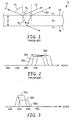
- the physics of this so-called "blue shift" of the reflection band can be explained in connection with FIG. 1 , where a portion of a multilayer film 10 is shown greatly enlarged.
- a light ray 12 is incident from medium 1 (with isotropic refractive index n 1 , for simplicity) at an angle ⁇ 1 .
- Part of the light ray reflects at an upper interface 14 between medium 1 and medium 2, and another part reflects at a lower interface 16 after traversing the layer of medium 2, whose physical thickness is d.
- Medium 2 is also assumed to have an isotropic refractive index, n 2 , for simplicity.
- the two reflected rays 18, 20 eventually constructively or destructively interfere depending on the relative phases of the rays.
- OPD optical path difference
- the band(s) shift to shorter wavelengths they also each split into two distinct bands: one for s-polarized light, the other for p-polarized light, where s-polarized light refers to linearly polarized light whose electric field vector oscillates perpendicular to the plane of incidence, and p-polarized light refers to linearly polarized light whose electric field vector oscillates parallel to the plane of incidence.
- the shift to shorter wavelengths can also be accompanied by a shift in the spectral width and shape of the reflection band, and changes in the out-of-band and in-band reflectivity.
- the amount of blue-shift one can attain is limited, and is a function of the medium in which the film is immersed, and the details of the film construction.
- the observed color change of these known films is a manifestation of the shift of the reflection band(s) to shorter wavelengths.
- the human-visible region corresponds to a segment of the electromagnetic spectrum extending from about 400 to 700 nm
- a film that is clear (i.e., substantially colorless) at normal incidence can become colored at oblique angles only by the shifting of a reflection band whose position at normal incidence is somewhere in the near infrared region, i.e., at or above about 700 nm.
- this band begins to move into the visible region with increasing observation angle, it begins to block long visible wavelengths in the red, thus giving rise to a cyan appearance in transmission. This is shown schematically in FIG.
- a reflection band 30a for normally incident light is located initially in the near infrared region of the spectrum, and then as the angle of observation increases it transforms into band 30b at shorter wavelengths, and with increasing observation angle transforms into band 30c at still shorter wavelengths.
- spectral ringing and separation into distinct s- and p- polarization reflection bands are ignored for ease of explanation.
- the spectral position of the reflection band at normal incidence is set by the optical thickness of the optical repeat units in the film.
- the optical thickness of a layer refers to its physical thickness multiplied by the relevant refractive index of light.
- Optical repeat unit refers to a stack of at least two individual layers that repeats across the thickness of a multilayer optical film, though all repeating layers need not have the same thickness.
- known clear-to-colored films reflect normally incident light from approximately 720 to 900 nanometers by utilizing optical repeat units whose optical thicknesses range from 360 to 450 nanometers (half the wavelength of the light desired to be reflected).
- the present application discloses films whose apparent color change with angle does not require the presence of a reflection band for normally incident light that then simply shifts to shorter wavelengths with increasing incidence angle.
- the present specification discloses an optical film having a plurality of layers effective to provide a reflection band covering a portion of the visible spectrum at an oblique angle such that the optical film appears colored at such oblique angle.
- the plurality of layers provide substantially no reflection bands for normally incident light.
- the specification discloses an optical film having layers that form a plurality of optical repeat units. At least some of the optical repeat units have optical thicknesses equal to half of a wavelength of visible light, yet the optical film has a clear appearance at normal incidence.
- the specification discloses optical films whose transmitted appearance changes from substantially clear to a first color over an angular range of observation angles. At least some of these optical films, however, do not appear cyan over such angular range.
- FIG. 3 provides a schematic representation of a reflection band for a film such as described herein.
- a curve 32a is provided merely to show that there is essentially no reflection band at all.
- a slight in-plane mismatch of refractive indices between individual layers may give rise to a barely perceptible reflection band, but the reflectivity of such band is generally less than 20%, more typically less than 10% or 5%. (Reflectivity values given herein assume illumination with unpolarized light unless otherwise noted.
- the reflectivity of a reflection band is understood herein to be the maximum reflectivity of such band exclusive of any outer surface reflections of the film.) As the observation angle increases, the reflection band appears in the visible region and increases in strength as shown by curve 32b. The reflection band increases still further with increasing observation angle as shown by curve 32c. The peak reflectivity of the reflection band thus increases substantially monotonically with increasing ⁇ , even though slight decreases in peak reflectivity of a few percent may in some circumstances occur with increasing ⁇ at low reflectivity values if the in-plane refractive index mismatch is significant. Although a blue shift can be seen in the sequence of FIG. 3 (as was the case in the sequence of FIG. 2), FIG.
- the reflection band essentially emerges from nowhere, rather than simply shifting over to the left.
- one or more reflection bands can be made to appear anywhere in the visible spectrum at a selected oblique angle in a manner like that shown in FIG. 3 , thus allowing the film to shift to any desired transmitted color at a selected oblique angle.
- Clear-to-green, clear-to-yellow, clear-to-magenta, clear-to-red, and clear-to-blue are examples of color shifts that are possible.
- a film can be considered clear if, having CIE color coordinates a* and b*, each are no greater than 5, or, more stringently, if the square root of a* 2 + b* 2 is no greater than 5. Note that although a great many embodiments exist where the film does not appear cyan over the useable range of entrance angles, in some embodiments the film may well appear cyan at some entrance angles, if it is so designed. If absorbing agents are added to change the baseline on-axis appearance from clear to a particular color, still further transitions are possible such as yellow-to-red or blue-to-green.
- the reflection band of FIG. 3 is associated with p-polarized light, not s-polarized light.
- the film is therefore a polarizing film at oblique angles. S-polarized light passes through the film without substantial reflection (except for possible outer surface reflections, which are not considered since they are substantially wavelength insensitive). Because of this, the reflection band of FIG. 3 can achieve a maximum reflectivity of 50% for unpolarized light, and the color saturation of the film (when illuminated with ordinary unpolarized light and viewed in transmission) will not be as great compared to a film that can filter both polarizations.
- the apparent color saturation can be greatly enhanced if the film is illuminated with only p-polarized light, or if it is observed through an analyzer that transmits only p-polarized light.
- the colored appearance of the film can be essentially eliminated even at highly oblique angles if the film is illuminated with only s-polarized light, or if it is observed through an analyzer that transmits only s-polarized light.
- the appearance of the film (whether colored or not, depending on the illumination and viewing conditions) is insensitive to rotations of the film about an axis perpendicular to the plane of the film, and to rotations of the observer about the film in such a way that the observation angle ⁇ is maintained constant.
- the film comprises alternating layers of a first and second light transmissible material A, B, which layers have optical thicknesses equal to one-fourth of the visible wavelength to be reflected.
- a pair of adjacent A,B layers then form an optical repeat unit whose optical thickness is 1 ⁇ 2 ⁇ .
- a variation of this is where the optical thicknesses of the layers are not equal, or in other words the f-ratio is different than 0.50.
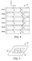
- FIG. 4 shows an optical film 40 is provided with alternating layers A and B that form six optical repeat units ORU1, ORU2, ... ORU6.
- optical thicknesses OT1, OT2,... OT6 which individually are the sum of the optical thicknesses of the applicable A layer and the adjacent B layer.
- typical films can include tens, hundreds, or thousands of individual layers.
- the optical repeat unit thicknesses can all be equal, in which case a relatively narrow reflection band is produced, or they can be different such as is the case with a linear gradient in layer thickness along the thickness axis of the film, producing a wider reflection band.
- Other layer thickness gradients can also be incorporated, such as described in U.S. Patent 6,157,490 (Wheatley et al. ), "Optical Film With Sharpened Bandedge".
- Film 40 is shown in the context of a local x-y-z right-handed Cartesian coordinate system, where the film extends parallel to the x-y plane, and the z-axis is perpendicular to the film, corresponding to a thickness axis.
- the refractive indices of the individual A layers are denoted: n 1 ⁇ x , n 1 ⁇ y , n 1 ⁇ z for polarized light whose electric field vector oscillates along the x-, y-, and z-axes respectively.
- the refractive indices of the individual B layers are denoted: n 2 ⁇ x , n 2 ⁇ y , n 2 ⁇ z .
- At least one of the A and B layers within each optical repeat unit is birefringent, such that there is a substantial match of refractive indices of adjacent layers along the in-plane axes, and a substantial mismatch of refractive indices along the thickness axis.
- ⁇ n z means large enough to produce a desired substantial amount of off-axis reflectivity, preferably at least 50% and more desirably at least 80% reflectivity for p-polarized light. These levels are achieved at oblique angles ⁇ (measured in an air medium) of typically 50 to 80 degrees, preferably about 60 degrees. A preferred value for ⁇ n z is about 0.1 or greater. The greater the value of ⁇ n z , the greater the reflectivity each optical repeat unit in the optical film for p-polarized light at a given oblique angle, and the greater the reflectivity of the film for a fixed number of optical repeat units, or the fewer optical repeat units required in the film for a desired reflectivity level. Reference is made to commonly assigned U.S. application serial number 10/334,836 , "P-Polarizer With Large Z-Axis Refractive Index Difference".
- a multilayer film with these refractive index relationships exhibits essentially no reflection bands for normally incident light. This is because the electric field vector of such light oscillates only along the in-plane axes, thereby sampling only the in-plane refractive indices. Since those indices are substantially matched from layer-to-layer, the light beam behaves as though traveling through a monolithic material with no internal interfaces. It is only when the light propagates at a substantial angle to the z-axis, and then only where the electric field vector has a component along the z-axis (p-polarized light), that a substantial refractive index difference is experienced by the light at the individual layer interfaces, thus giving rise to reflection by constructive interference.
- the optical repeat units should have optical thicknesses that produce at an oblique angle a reflectivity over the human visible spectrum that is non-uniform, so that the film exhibits a colored appearance in transmitted light at such angle.
- the optical thicknesses of the optical repeat units can be chosen to all be equal such that a single, relatively narrow reflection band emerges in a desired portion of the visible spectrum with increasing incidence angle.
- multiple packets of optical repeat units can be used, where each packet has optical repeat units of a uniform optical thickness, but such optical thickness being different for the different packets so that distinct narrow reflection bands emerge in a desired part of the visible spectrum.
- thickness gradients can be employed to produce broadened reflection bands over portions of the visible spectrum.
- Multiple reflection bands can be separated by a sufficient degree to define a spectral region of high transmission (a transmission band) therebetween over a desired wavelength band such as blue, green, or red.
- a desired wavelength band such as blue, green, or red.
- Appropriate selection of the thicknesses of the optical repeat units therefore give the designer wide latitude to achieve nearly any desired color appearance at the oblique observation angle, not only cyan, even for a film that is substantially clear at normal incidence.
- the reflectivity of a given optical repeat unit exhibits a maximum at a wavelength ⁇ equal to two times the optical thickness of the optical repeat unit, at normal incidence.
- the optical thickness of an optical repeat unit is considered to be a constant, and equal to the sum of the optical thicknesses of the optical repeat unit's constituent optical layers for normally incident light.
- At least some (and preferably substantially all) of the optical repeat units in the subject films reflect visible light over a range of nonzero angles of incidence, i.e., over a range of oblique angles of incidence.
- optical films described herein will nevertheless have at least some optical repeat units whose (normal incidence) optical thickness is equal to half of a wavelength of visible light, or half of a wavelength between about 400 and 700 nm, or from about 200 to 350 nm, while also having a normal angle transmitted appearance that is substantially clear and/or having substantially no reflection bands at normal incidence, whether in the visible or near infrared regions.
- each optical repeat unit can consist essentially of just two light transmissible optical layers.
- optical repeat unit designs can also be used in accordance with the above teachings.
- four layer designs using three different materials as described in U.S. Patent 5,103,337 (Schrenk et al. ), "Infrared Reflective Optical Interference Film”, and six layer designs using two materials as described in U.S. Patent 5,360,659 (Arends et al. ), "Two Component Infrared Reflecting Film”, can also be used.
- a simple two-component quarter-wave (0.50 f-ratio) design is preferred since it provides high reflectivity for the lowest order reflection and since higher order reflections are generally of no concern.
- a variety of light transmissible materials can be used for the optical layers making up the optical repeat units of the subject films.
- the materials are thermoplastic polymers that can be co-extruded from a multilayer die and subsequently cast and oriented in sequential or simultaneous stretching operations.
- Optically thick skin layers can be added for protection and ease of handling, which layers can become protective boundary layers between packets of optical layers within the finished film if one or more layer multipliers is used between the feedblock and the die.
- one light transmissible polymeric material (arbitrarily designated A) remains isotropic throughout the manufacturing process, and another (arbitrarily designated B) becomes birefringent during a stretching procedure in the manufacturing process.
- the stretching is carried out along both x- and y- axes so that the in-plane refractive indices of the birefringent material end up being about equal to each other, and equal to the refractive index of the isotropic material.
- the out-of-plane refractive index of the birefringent material then differs substantially from the refractive index of the isotropic material.
- material A has a relatively high (isotropic) refractive index and material B has a somewhat lower isotropic refractive index in the cast film before orientation.
- the refractive indices of the B material increase along the two orthogonal stretch directions to match the index of the A material, and the z-axis refractive index of the B material diminishes to widen the gap between it and the index of the A material.
- the stretch conditions such as film temperature, stretch rate, and stretch ratio
- Material A has a high refractive index to match the in-plane refractive indices of the oriented material B, and a low enough glass transition temperature T g to remain isotropic when oriented at conditions necessary to cause birefringence in material B.
- the film is maintained at a temperature of at least about 20°C above the glass transition temperature of the isotropic material during stretching.
- conventional absorbing agents such as dyes and pigments can be added to one or more layers of the film, or can be applied in one or more coatings such as an adhesive, ink, or hard coat, or incorporated in a separate film or substrate that is subsequently laminated to the subject multilayer optical films, to add a baseline color or tint to the film or article for visual effect.
- This baseline color would of course be effective at essentially all viewing angles.
- Additional layers and coatings can also be added to modify optical, mechanical, or chemical properties of the film. See U.S. Patent No. 6,368,699 (Gilbert et al. ), "Multilayer Polymer Film With Additional Coatings or Layers".
- Conventional multilayer films and polarizers other than p-polarizing films can also be laminated to or otherwise used with the films described herein.
- Such conventional films may have reflection bands in the visible and/or near infrared regions of the spectrum for aesthetic and/or utilitarian purposes.
- the unique appearance characteristics of the subject films can be further modified by selectively thinning portions of the film to define a feature, pattern, or indicia.
- selective thinning preferably involves more than simply thinning a skin layer or coating, but rather thinning all the optical layers through the thickness of the film at the localized positions so that the perceived color at oblique angles is changed at those positions. This can be done by localized heating, embossing, or exposure to suitable laser radiation.
- the thinning is done after the desired refractive index relationships are established through the orientation process. In that way both the thinned portions and the remaining portions exhibit the desirable refractive index and wavelength properties described above. An example is shown in FIG. 5 .
- portion 52 has been thinned in the form of a corporate logo on an optical film 50 that also includes unthinned portion or background 54.
- the in-plane refractive indices of adjacent optical layers are substantially matched, and the out-of-plane refractive indices of such layers are substantially mismatched.
- the film 50 can be completely clear, or of a uniform color if absorbing agents are present.
- the unthinned portion 54 changes to a first transmitted color and thinned portion 52 changes to a second transmitted color that is blue-shifted relative to the color of portion 54, the amount of blue-shift being proportional to the degree of thinning of the optical layers.
- the pattern is difficult to detect at normal viewing but becomes clearly visible at oblique angles.
- the pattern can incorporate more than two portions, each having a distinct thickness and hence a distinct color at oblique angles, and can also incorporate a gradual thickness change from one portion of the film to the other rather than step changes.
- indicia can be added to the films by localized surface roughening or texturing.
- roughening scatters both s- and p-polarized light, and roughened regions stand out from the surrounding optical film.
- Localized surface texturing can be achieved by a variety of known techniques, such as laser marking, sandblasting, embossing with a matte finish roll, rubbing, and impinging jets.
- Films as described herein and articles incorporating such films can be used in a variety of end-use applications.
- specialized optical systems can benefit from the unique properties of a p-polarizer. See, for example, commonly assigned U.S. Application Serial No. 10/335,458 , "Head-Up Display With Polarized Light Source and Wide-Angle P-Polarization Reflective Polarizer".
- Another end-use application is the area of authentication systems.
- the subject films can be permanently affixed to a document, such as a passport, so that an observer can read the document through the film, but can also tell whether the document is authentic by observing the unique color shift at oblique angles, optionally with an analyzing polarizer or with polarized light.
- the document or other substrate over which the film is applied can include indicia that are colored in such a way that the transmitted color of the film at an oblique angle matches the color of the indicia making them difficult to read, while they are easily read at normal incidence.
- the films can be sold in the form of a tape or label, which can be adhesively secured to a document or to a package for consumer goods, again for purposes of authentication.
- the films can also be sold in the form of a security thread to be incorporated into a security document.
- Conventional printed images and/or holographic images can be provided on either major surface of the films, by any suitable technique.
- Other conventional security features that can be incorporated into the subject films, or any suitable construction of which the film is a part, include microperforations that effectively prevent tampering, heat shrink characteristics that prevent tempering by the application of heat, patterned differential adhesion layers that effectively prevent tempering by delamination, and internal delamination characteristics that provide an indication of tampering.
- the subject films can also be incorporated into any suitable label, laminate, or card (such as an identification card or transparent or translucent financial transaction card), whether on the surface or in an interior layer of such item.
- the polymer used in the isotropic layers of the film construction was specially formulated to achieve the necessary rheological; chemical, thermal, and optical properties.
- the polymers used in the film were chosen and/or developed according to the following conditions: they should be coextrudable; they should have adequate interlayer adhesion; and the isotropic polymer should have an unusually high refractive index in order to match the in-plane refractive indices of the birefringent polymer after stretching, and a low enough glass transition temperature so that it remains isotropic when oriented under conditions necessary to cause birefringence in the other polymer material.
- the film is maintained at a temperature of at least about 20°C above the glass transition temperature of the isotropic material during stretching.
- a copolyester was synthesized in a batch reactor with the following raw material charge: 127.3 kg dimethyl naphthalene dicarboxylate, 4.2 kg dimethyl isophthalate, 38.4 kg hexane diol, 50.5 kg ethylene glycol, 8.6 kg 1,3 butyl ethyl propanediol, 1.3 kg trimethylol propane, 34 g zinc acetate, 25 g cobalt acetate, and 75 g antimony triacetate. Under pressure of 0.20 MPa, this mixture was heated to 254°C while removing methanol. After 34.5 kg of methanol was removed, 56 g of triethyl phosphonoacetate was charged to the reactor and then the pressure was gradually reduced to 133 Pa while heating to 285°C.
- the condensation reaction by-product ethylene glycol
- ethylene glycol was continuously removed until a polymer with an intrinsic viscosity of 0.84 dL/g, as measured in 60/40 wt.% phenol/o-dichlorobenzene at 86°C, was produced.
- This material a thermoplastic polymer, had a glass transition temperature Tg of 76°C as measured by DSC using ASTM D3418 with a scan rate of 20°C /min, and at a relative humidity of about 50%.
- the thermal history of the polymer was removed as a factor by performing two DSC heat scans on the sample and recording the T g of the second heat scan.
- the polyethylene terephthalate used in the example is synthesized in a batch reactor with the following raw material charge: 5,000 kg dimethyl terephthalate, 3,502 kg ethylene glycol, 1.2 kg manganese acetate, and 1.6 kg antimony triacetate. Under pressure of 1520 torr, this mixture is heated to 254°C while removing the transesterification reaction by-product methanol. After 1,649 kg of methanol is removed, 2.45 kg of triethyl phosphonoacetate is charged to the reactor and then the pressure is gradually reduced to 1 torr while heating to 280°C.
- the condensation reaction by-product ethylene glycol
- ethylene glycol is continuously removed until a polymer with an intrinsic viscosity of 0.60 dL/g, as measured in 60/40 wt.% phenol/o-dichlorobenzene at 86°C, is produced.
- This material a thermoplastic polymer, has a glass transition temperature T g of 79°C and a melting temperature T m of 255°C as measured by DSC using ASTM D3418 with a scan rate of 20°C /min, and at a relative humidity of about 50%.
- the thermal history of the polymer is removed as a factor by performing two DSC heat scans on the sample and recording the T g of the second heat scan.
- This copolyester was obtained commercially from Eastman Chemical Company, Kingsport, Tennessee, under product code Eastar brand PETG 6763. It exhibits a glass transition temperature T g of 83°C.
- a multilayer optical polarizing film was made using Polymer 1 as one of the light transmissible materials, and Polymer 4 (the blend of 70 wt% PET and 30 wt% PETG) for the other material. These materials were coextruded through a multi-layer melt manifold to create a stack of 275 alternating layers of Polymer 1 and Polymer 4. An additional set of thick external protective skin layers made from Polymer 4 were coextruded on either side of the 275 layer stack to form a cast web with 277 total layers and a total thickness of 0.021 inches (0.53 mm). In this cast web, all layers were isotropic in refractive index, with Polymer 1 having an index of about 1.618 and Polymer 4 having an index of about 1.567 at visible wavelengths.
- a piece of this cast web was then heated by impingement with hot air at 100°C for 45 seconds and then oriented simultaneously in two orthogonal in-plane directions at a draw rate of 100%/sec to a final draw ratio of 3.6 x 3.6.
- the resulting optical film had a thickness of about 0.0016 inches (0.041 mm) and a useable area of about 10 by 10 inches (about 650 cm 2 ).
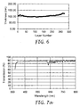
- the resulting physical thickness profile of the 275 optical layers in the film is shown in FIG. 6 .
- adjacent layers have approximately the same physical thickness, and hence in this case also approximately the same on-axis optical thickness (f-ratio ⁇ 0.50).
- f-ratio ⁇ 0.50 on-axis optical thickness
- multiple distinct nonzero layer thickness gradients can be detected over various segments of the film thickness.
- the individual optical layers range in physical thickness from just under about 100 nm to about 125 nm. With the refractive index properties of the two materials as noted above, these thicknesses yield optical repeat units whose optical thicknesses range from just under 325 nm to about 405 nm. Doubling these values correspond to optical wavelengths of just under 650 nm to about 810 nm.
- FIG. 7a and 7b for normally incident light and light incident at 60°, respectively.
- curve 60 is the transmission of s-polarized light only
- curve 62 is for p-polarized light only.
- the FIG. 7a-b graphs include no corrections or offsets for the broadband surface reflections at the front and rear film-air interfaces. Note the absence of any substantial reflection bands at normal incidence. Note also the presence of a significant reflection band for p-polarized light in the visible region at 60° incidence. The approximately 50% broadband reflectivity of s-polarized light in FIG. 7b is due to the film-air surface reflections.
- the polymer used as the isotropic layer desirably has a refractive index of at least about 1.61, more desirably about at least 1.65, so that polymers that exhibit greater birefringence (e.g., pure PET) can be used to help increase the z-index differential between optical layers to achieve higher reflectivity.
- polymers that exhibit greater birefringence e.g., pure PET
- a copolyester was synthesized in a batch reactor with the following raw material charge: 87.6 kg dimethyl naphthalene dicarboxylate, 57 kg dimethyl terephthalate, 12.3 kg hexane diol, 81.6 kg ethylene glycol, 0.7 kg trimethylol propane, 34 g zinc acetate, 25 g cobalt acetate, and 55 g antimony triacetate. Under pressure of 0.20 MPa, this mixture was heated to 254°C while removing methanol. After 41.5 kg of methanol was removed, 56 g of triethyl phosphonoacetate was charged to the reactor and then the pressure was gradually reduced to 133 Pa while heating to 285°C.
- the condensation reaction by-product ethylene glycol
- ethylene glycol was continuously removed until a polymer with an intrinsic viscosity of 0.53 dL/g, as measured in 60/40 wt.% phenol/o-dichlorobenzene at 86°C, was produced.
- This material a thermoplastic polymer, had a glass transition temperature T g of 92°C as measured by DSC using ASTM D3418 with a scan rate of 20°C /min, and at a relative humidity of about 50%.
- the thermal history of the polymer was removed as a factor by performing two DSC heat scans on the sample and recording the T g of the second heat scan.
- the polymer is suitable for use in the isotropic optical layers of a multilayer film, and has a refractive index of 1.612.
- the isotropic refractive index of coPEN-HNLT described as Polymer 1 can be increased to 1.65 by incorporation of about 30 wt% titania particles with average particle size of less than about 30 nm. Titania itself has a refractive index of about 2.4 in the visible.
- the nano-titania particles should be adequately dispersed to avoid excessive haze or scattering of light in the polymer matrix.
- thermoplastic polymer-based material has the same glass transition temperature as Polymer 1, i.e., about 76°C, and is suitable for use in the isotropic optical layers of a multilayer film.
- the isotropic refractive index of coPEN-HNLT described as Polymer 1 can be increased to 1.65 by incorporation of about 40 wt% zirconia particles with average particle size of less than about 30 nm. Zirconia itself has a refractive index of about 2.2 in the visible. The nano-zirconia particles should be adequately dispersed to avoid excessive haze or scattering of light in the polymer matrix.
- thermoplastic polymer-based material has the same glass transition temperature as Polymer 1, i.e., about 76°C, and is suitable for use in the isotropic optical layers of a multilayer film.
- Copolymers of naphthyl thio-acrylate and naphtyl thioethyl acrylate and/or naphthyl oxyethyl acrylate can be synthesized with 30 wt% titania particles to produce a polymer-based material having an isotropic refractive index of approximately 1.65.
- the titania particles which should have an average size of less than about 30 nm, should be adequately dispersed to avoid excessive haze or scattering of light in the acrylate polymer matrix.
- the glass transition temperature of this polymer-based material can be tailored by adjusting the relative proportions of the acrylate monomers, since T g ⁇ 100°C for naphthyl thio-acrylate, T g ⁇ 40°C for naphtyl thioethyl acrylate, and T g ⁇ 9°C for naphthyl oxyethyl acrylate.
- the glass transition temperature of the material can be tailored to be below 79°C, the glass transition temperature of PET.
- This Polymer 8 is suitable for use in the isotropic optical layers of a multilayer film.
- Copolymers of naphthyl thio-acrylate and naphtyl thioethyl acrylate and/or naphthyl oxyethyl acrylate can be synthesized with 40 wt% zirconia particles to produce a polymer-based material having an isotropic refractive index of approximately 1.65.
- the zirconia particles which should have an average size of less than about 30 nm, should be adequately dispersed to avoid excessive haze or scattering of light in the acrylate polymer matrix.
- thermoplastic polymer-based material can be tailored by adjusting the relative proportions of the acrylate monomers, as described above in connection with Polymer 8, and can be tailored to be below 79°C.
- This Polymer 9 is suitable for use in the isotropic optical layers of a multilayer film.
- a copolyester can be synthesized in a batch reactor with the following raw material charge: 127.3 kg 2,6-dimethyl naphthalene dicarboxylate, 8.4 kg 2,3-dimethyl naphthalene dicarboxylate, 48.4 kg hexane diol, 50.5 kg ethylene glycol, 8.6 kg 1,3 butyl ethyl propanediol, 1.3 kg trimethylol propane, 34 g zinc acetate, 25 g cobalt acetate, and 75 g antimony triacetate. Under pressure of 0.20 MPa, this mixture can then be heated to 254°C while removing methanol. After 32.5 kg of methanol is removed, 56 g of triethyl phosphonoacetate can be charged to the reactor and then the pressure gradually reduced to 133 Pa while heating to 285°C.
- the condensation reaction by-product ethylene glycol
- ethylene glycol can be continuously removed until a polymer with an intrinsic viscosity of at least 0.6 dL/g, as measured in 60/40 wt.% phenol/o-dichlorobenzene at 86°C, is produced.
- This material a thermoplastic polymer, has a glass transition temperature T g of approximately 76°C as measured by DSC using ASTM D3418 with a scan rate of 20°C /min, and at a relative humidity of about 50%.
- thermoplastic polymer is suitable for use in the isotropic optical layers of a multilayer film, and has a refractive index of 1.63.
- a copolyester was synthesized in a batch reactor with the following raw material charge: 100 kg dimethyl terephthalate, 93 kg 1,6-hexane diol, 3.1 kg triethylene glycol, 0.9 kg trimethylol propane, 50 g tetra butly titanate, 30 g cobalt acetate, and 35 g antimony triacetate. Under pressure of 0.20 MPa, this mixture was heated to 254°C while removing methanol. After 33 kg of methanol was removed, 35 g of triethyl phosphonoacetate was charged to the reactor and then the pressure was gradually reduced to 133 Pa while heating to 270°C.
- the condensation reaction by-product, 1,6 hexane diol was continuously removed until a polymer with an intrinsic viscosity of 0.86 dL/g, as measured in 60/40 wt.% phenol/o-dichlorobenzene at 86°C, was produced.
- This material a thermoplastic polymer, had a glass transition temperature Tg of 15°C and a melting temperature T m of 142°C as measured by DSC using ASTM D3418 with a scan rate of 20°C /min, and at a relative humidity of about 50%.
- the thermal history of the polymer was removed as a factor by performing two DSC heat scans on the sample and recording the T g of the second heat scan.
- the polymer is suitable for use in the birefringent optical layers of a multilayer film, and has a pre-stretch refractive index of about 1.55. Under suitable biaxial stretching conditions, the in-plane refractive indices can increase to about 1.59 to 1.61 and the out-of-plane refractive index can diminish to about 1.51.
- the polymer is suitable for use in the birefringent optical layers of a multilayer film, and has a pre-stretch refractive index of about 1.568. Under suitable biaxial stretching conditions, the in-plane refractive indices can increase to about 1.638 and the out-of-plane refractive index can diminish to about 1.506.
- Copolymers of vinyl naphthalene and phenoxy ethyl acrylate or other low Tg acrylates such as ethyl acrylate, butyl acrylate, and iso-octyl acrylate can be synthesized to provide a refractive index of 1.65 and a glass transition temperature of less than 79°C.
- butadiene or other low T g rubber comonomers can be copolymerized with vinyl naphthalate to provide a refractive index of 1.65 and a glass transition temperature of less than 79°C.
- Atactic polyvinyl naphthalene has an isotropic refractive index of 1.68 and thus can be useful for increasing the index difference along the z-axis for increased reflectivity.
- the Tg of this material is 151°C, and hence it would be suitable for coextrusion and orientation with a higher T g CoPEN as the birefringent material designed to have in-plane refractive indices of 1.68-1.70 after orientation.
- Copolymers of PEN can be synthesized utilizing 2,6 dimethyl naphthalate and 2,3 dimethyl naphthalate or 4,4 biphenyl dicarboxylate as comonomers to dilute the in-plane refractive indices of PEN down to 1.68-1.7 so as to match those of atactic PVN as the istotropic material.
- a multilayer optical polarizing film can be made using Polymer 5 as the isotropic light transmissible material, and Polymer 11 (the co-PHT) as the birefringent light transmissible material. These materials can be coextruded through a multi-layer melt manifold to create a stack of 275 (or other suitable number of) alternating layers of Polymer 5 and Polymer 11. An additional set of thick external protective skin layers made from Polymer 11 can be coextruded on either side of the 275 layer stack to form a cast web with 277 total layers and a total thickness of, say, about 0.019 inches (0.48 mm) or other suitable value.
- This cast web all layers are isotropic in refractive index, with Polymer 5 having an index of about 1.612 and Polymer 11 having an index of about 1.55 at visible wavelengths.
- This cast web can then be heated to a suitable temperature, such as 115°C, by impingement with hot air or other conventional heating means and oriented simultaneously in two orthogonal in-plane directions at a suitable draw rate, such as 1000%/sec, to a final draw ratio such as 3.0 x 3.0.
- the resulting optical film can have a thickness of about 0.002 inches (0.05 mm).
- the refractive index of the other polymer can remain isotropic by appropriate selection of the stretch conditions, with an isotropic refractive index of 1.612:
- ⁇ ⁇ n x ⁇ ⁇ n y ⁇ 0.002 ⁇ ⁇ n z ⁇ 0.102
- the thickness profile of the optical layers in the finished film can be any suitable function that achieves the desired transmitted color at an oblique angle, whether uniform, step, linear, or other known function.
- the in-plane refractive index difference is well below 0.01, yielding a film that is substantially clear when viewed at 0° observation angle even if each and every optical repeat unit in the film has an optical thickness of half of a visible wavelength.
- a multilayer optical polarizing film can be made using Polymer 1 as the isotropic light transmissible material, and Polymer 12 (the blend of 80 wt% PET and 20 wt% PETG) as the birefringent material. These materials can be coextruded through a multi-layer melt manifold to create a stack of 223 (or other suitable number of) alternating layers of Polymer 1 and Polymer 12.
- the stack need not have any layer thickness gradient, but preferably does have a gradient corresponding to a full-width at half-maximum (FWHM) bandwidth of the reflection band in the finished film of about 100 nm.
- FWHM full-width at half-maximum
- This stack can be provided to an asymmetric multiplier where the extrudate is split into unequal widths of a suitable ratio, such as about 1:1.44, and stacked after equalizing the widths to provide two optical packets and a total of 445 optical layers.
- An additional set of thick external protective skin layers made from Polymer 12 can be coextruded on either side of the 445 layers to form a cast web with 447 total layers and a total thickness of 0.020 inches (0.51 mm). In this cast web, all layers are isotropic in refractive index, with Polymer 1 having an index of about 1.618 and Polymer 12 having an index of about 1.568 at visible wavelengths.
- This cast web can then be heated by impingement with hot air at 102°C and then oriented in two orthogonal in-plane directions at a suitable draw rate to a final draw ratio of about 3.5 x 3.5.
- the refractive index of the other polymer can remain isotropic by appropriate selection of the stretch conditions, with an isotropic refractive index of 1.618:
- the resulting optical film can provide, for obliquely-incident light, two distinct p-polarization reflection bands corresponding to the two 223 layer packets in the film.
- the reflection bands can be separated sufficiently to define a gap therebetween characterized by low reflectivity and high transmission.
- a film that shifts in transmitted appearance from clear at normal incidence to green at about 60° can be provided.
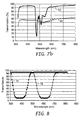
- Computed transmission spectra at 60° incidence and for p-polarized light only are shown in FIG. 8 , where the curves 70, 72 are the computed transmission of the two individual packets that make up the film. As demonstrated, each packet produces a strong reflection band at the oblique angle.
- a multilayer optical interference film can be made in the same way as the Example Film, except the layer thickness can be controlled to provide a substantially linear layer thickness gradient across the thickness of the film between limits that provide a single reflection band extending from about 500 nm to about 600 nm for p-polarized light at 60°.
- a yellow dye (absorbing from about 400 to 500 nm) is incorporated into the film (or in a separate film or coating laminated or otherwise applied to the multilayer film) in an amount sufficient to provide a yellow baseline color to the film at normal viewing.
- FIG. 9 exemplifies the absorption of the yellow dye with curve 76, which curve is relatively insensitive to changes in viewing or incidence angle ⁇ .
- Curve 78 changes greatly with viewing angle, becoming a flat line at the upper end of the percent transmission scale for normally incident light.
- the yellow dye is replaced with a blue dye that absorbs from about 600 to 700 nm.
- birefringent light transmissible material is Polymer 2 (PET)
- the isotropic light transmissible material is selected from the group of Polymer 6 (co-PEN with nano-titania), Polymer 7 (co-PEN with nano-zirconia), Polymer 8 (acrylate with nano-titania), and Polymer 9 (acrylate with nano-zirconia).
- PET Polymer 2
- Isotropic material n x ⁇ n y ⁇ n z ⁇ 1.65
- Birefringent material (Polymer 2): n x ⁇ n y ⁇ 1.65; n z ⁇ 1.49 And thus, ⁇ ⁇ n x ⁇ ⁇ ⁇ n y ⁇ 0 ⁇ ⁇ n z ⁇ 0.16
- the relatively large z-index difference-greater than 0.15- provides substantially higher reflectivity for off-axis p-polarized light.
- a good in-plane index match ensures substantially no reflection bands at normal incidence.
- Another material pair of interest for the p-polarizing multilayer optical film is a combination in which the birefringent light transmissible material is Polymer 12 (80% PET/ 20% PETG) and the isotropic light transmissible material is Polymer 10 (High Index co-PEN).
- sPS siniotactic polystyrene
- sPN siniotactic polynaphthalene
- the isotropic polymer should be chosen such that its refractive indices are lower than that of either sPS or sPN.
- the refractive indices of sPS are 1.585 before orientation and after stretching the in-plane refractive indices derease to 1.56 and the z-axis refractive index increases to 1.65.
- a copolymer such as PETG can be used as the isotropic polymer to give the following sets of refractive indices after orientation: PETG : n x ⁇ n y ⁇ n z ⁇ 1.56 sPS : n x ⁇ n y ⁇ 1.56 ; n z ⁇ 1.65 ⁇ n x ⁇ ⁇ n y ⁇ 0.0 ⁇ n z ⁇ 0.09
- F-ratio the relative contribution of a given individual layer to the total optical thickness of a given ORU.
- n k (n m ) is the relevant refractive index of k-th (m-th) layer
- d k (d m ) is the physical thickness of layer k (m).
- ORU Optical Repeat Unit
- Optical thickness the physical thickness of a given body times its refractive index. In general, this is a function of wavelength and polarization.
- Reflection band a spectral region of relatively high reflectance bounded on either side by regions of relatively low reflectance.
Applications Claiming Priority (2)
| Application Number | Priority Date | Filing Date | Title |
|---|---|---|---|
| US10/335,460 US7064897B2 (en) | 2002-12-31 | 2002-12-31 | Optical polarizing films with designed color shifts |
| EP03814971.2A EP1588198B1 (fr) | 2002-12-31 | 2003-12-24 | Films de polarisation optique avec décalage de couleur dépendant de l'angle d'inidence, les films n'ayant pas de bandes de réflexion dans la partie visible du spectre pour incidence normale |
Related Parent Applications (2)
| Application Number | Title | Priority Date | Filing Date |
|---|---|---|---|
| EP03814971.2A Division EP1588198B1 (fr) | 2002-12-31 | 2003-12-24 | Films de polarisation optique avec décalage de couleur dépendant de l'angle d'inidence, les films n'ayant pas de bandes de réflexion dans la partie visible du spectre pour incidence normale |
| EP03814971.2A Division-Into EP1588198B1 (fr) | 2002-12-31 | 2003-12-24 | Films de polarisation optique avec décalage de couleur dépendant de l'angle d'inidence, les films n'ayant pas de bandes de réflexion dans la partie visible du spectre pour incidence normale |
Publications (1)
| Publication Number | Publication Date |
|---|---|
| EP1980881A1 true EP1980881A1 (fr) | 2008-10-15 |
Family
ID=32655354
Family Applications (3)
| Application Number | Title | Priority Date | Filing Date |
|---|---|---|---|
| EP16165090.8A Expired - Lifetime EP3067721B1 (fr) | 2002-12-31 | 2003-12-24 | Films polarisants optiques dotés de décalages de couleurs |
| EP08011860A Ceased EP1980881A1 (fr) | 2002-12-31 | 2003-12-24 | Films polarisants optiques dotés de décalages de couleurs |
| EP03814971.2A Expired - Lifetime EP1588198B1 (fr) | 2002-12-31 | 2003-12-24 | Films de polarisation optique avec décalage de couleur dépendant de l'angle d'inidence, les films n'ayant pas de bandes de réflexion dans la partie visible du spectre pour incidence normale |
Family Applications Before (1)
| Application Number | Title | Priority Date | Filing Date |
|---|---|---|---|
| EP16165090.8A Expired - Lifetime EP3067721B1 (fr) | 2002-12-31 | 2003-12-24 | Films polarisants optiques dotés de décalages de couleurs |
Family Applications After (1)
| Application Number | Title | Priority Date | Filing Date |
|---|---|---|---|
| EP03814971.2A Expired - Lifetime EP1588198B1 (fr) | 2002-12-31 | 2003-12-24 | Films de polarisation optique avec décalage de couleur dépendant de l'angle d'inidence, les films n'ayant pas de bandes de réflexion dans la partie visible du spectre pour incidence normale |
Country Status (10)
| Country | Link |
|---|---|
| US (3) | US7064897B2 (fr) |
| EP (3) | EP3067721B1 (fr) |
| JP (1) | JP4594104B2 (fr) |
| KR (1) | KR101029441B1 (fr) |
| CN (1) | CN100373188C (fr) |
| AU (1) | AU2003300384B2 (fr) |
| BR (1) | BR0317843A (fr) |
| CA (1) | CA2511787A1 (fr) |
| MX (1) | MXPA05007058A (fr) |
| WO (1) | WO2004061491A2 (fr) |
Cited By (2)
| Publication number | Priority date | Publication date | Assignee | Title |
|---|---|---|---|---|
| CN102576113A (zh) * | 2009-10-24 | 2012-07-11 | 3M创新有限公司 | 具有减少色彩的浸没式不对称反射器 |
| EP2376956A4 (fr) * | 2008-12-22 | 2017-11-01 | 3M Innovative Properties Company | Films optiques multicouches à motifs internes employant la réduction de biréfringence spatialement sélective |
Families Citing this family (79)
| Publication number | Priority date | Publication date | Assignee | Title |
|---|---|---|---|---|
| US6952312B2 (en) * | 2002-12-31 | 2005-10-04 | 3M Innovative Properties Company | Head-up display with polarized light source and wide-angle p-polarization reflective polarizer |
| US7094461B2 (en) * | 2002-12-31 | 2006-08-22 | 3M Innovative Properties Company | P-polarizer with large z-axis refractive index difference |
| US7064897B2 (en) * | 2002-12-31 | 2006-06-20 | 3M Innovative Properties Company | Optical polarizing films with designed color shifts |
| EP2279909B1 (fr) * | 2005-02-02 | 2012-06-06 | Flabeg GmbH & Co. KG | Rétroviseur pour véhicules |
| US20060293463A1 (en) * | 2005-06-28 | 2006-12-28 | General Electric Company | Compositions for brightness enhancing films |
| US20070044043A1 (en) * | 2005-08-22 | 2007-02-22 | Schut David M | DBR film for laser imaging |
| US20080037127A1 (en) * | 2006-03-31 | 2008-02-14 | 3M Innovative Properties Company | Wide angle mirror system |
| US7636193B2 (en) * | 2006-05-02 | 2009-12-22 | 3M Innovative Properties Company | Visible light-transmissive IR filter with distorted portions |
| US20070279755A1 (en) * | 2006-06-01 | 2007-12-06 | 3M Innovative Properties Company | Head-Up Display System |
| JP5676104B2 (ja) * | 2006-09-29 | 2015-02-25 | スリーエム イノベイティブ プロパティズ カンパニー | ポリマーベースの光学素子におけるアーチファクトの生成を抑制する接着剤 |
| US8522990B2 (en) * | 2007-03-23 | 2013-09-03 | Selig Sealing Products, Inc. | Container seal with removal tab and holographic security ring seal |
| US9624008B2 (en) | 2007-03-23 | 2017-04-18 | Selig Sealing Products, Inc. | Container seal with removal tab and security ring seal |
| US8703265B2 (en) * | 2007-03-23 | 2014-04-22 | Selig Sealing Products, Inc. | Container seal with removal tab and piercable holographic security seal |
| US9770611B2 (en) | 2007-05-03 | 2017-09-26 | 3M Innovative Properties Company | Maintenance-free anti-fog respirator |
| US20080271739A1 (en) | 2007-05-03 | 2008-11-06 | 3M Innovative Properties Company | Maintenance-free respirator that has concave portions on opposing sides of mask top section |
| US9063291B2 (en) * | 2007-08-12 | 2015-06-23 | Toyota Motor Engineering & Manufacturing North America, Inc. | Omnidirectional reflector |
| US9612369B2 (en) | 2007-08-12 | 2017-04-04 | Toyota Motor Engineering & Manufacturing North America, Inc. | Red omnidirectional structural color made from metal and dielectric layers |
| US9229140B2 (en) * | 2007-08-12 | 2016-01-05 | Toyota Motor Engineering & Manufacturing North America, Inc. | Omnidirectional UV-IR reflector |
| US10048415B2 (en) | 2007-08-12 | 2018-08-14 | Toyota Motor Engineering & Manufacturing North America, Inc. | Non-dichroic omnidirectional structural color |
| US10788608B2 (en) | 2007-08-12 | 2020-09-29 | Toyota Jidosha Kabushiki Kaisha | Non-color shifting multilayer structures |
| US10870740B2 (en) | 2007-08-12 | 2020-12-22 | Toyota Jidosha Kabushiki Kaisha | Non-color shifting multilayer structures and protective coatings thereon |
| US10690823B2 (en) | 2007-08-12 | 2020-06-23 | Toyota Motor Corporation | Omnidirectional structural color made from metal and dielectric layers |
| US8736959B2 (en) * | 2007-08-12 | 2014-05-27 | Toyota Motor Engineering & Manufacturing North America, Inc. | Omnidirectional reflector |
| US9739917B2 (en) | 2007-08-12 | 2017-08-22 | Toyota Motor Engineering & Manufacturing North America, Inc. | Red omnidirectional structural color made from metal and dielectric layers |
| BRPI0815325A2 (pt) | 2007-08-24 | 2019-09-24 | Selig Sealing Products Inc | substrato de cobertura capaz de ser aglutinado a um aro de um recipiente, método de cobrir higienicamente uma porção de topo de um recipiente e recipiente coberto higienicamente |
| JP4513921B2 (ja) * | 2008-12-09 | 2010-07-28 | ソニー株式会社 | 光学体およびその製造方法、窓材、ブラインド、ロールカーテン、ならびに障子 |
| CN102307724B (zh) * | 2009-02-06 | 2015-05-13 | 3M创新有限公司 | 光控膜和多层光学膜叠堆 |
| JP2011126182A (ja) * | 2009-12-18 | 2011-06-30 | Teijin Ltd | 1軸延伸多層積層フィルム、それからなる輝度向上用部材、それらからなる液晶ディスプレイ用複合部材およびそれらからなる液晶ディスプレイ装置 |
| JP4782864B2 (ja) * | 2009-12-18 | 2011-09-28 | 帝人株式会社 | 1軸延伸多層積層フィルム、それからなる輝度向上用部材、それらからなる液晶ディスプレイ用複合部材およびそれらからなる液晶ディスプレイ装置 |
| JP5022480B2 (ja) * | 2010-06-30 | 2012-09-12 | 帝人株式会社 | 液晶表示装置用液晶パネルおよびそれからなる液晶表示装置 |
| EP2514592B1 (fr) * | 2009-12-18 | 2014-08-20 | Teijin Limited | Film étirable multicouche |
| WO2011146288A1 (fr) * | 2010-05-21 | 2011-11-24 | 3M Innovative Properties Company | Films optiques multicouches partiellement réfléchissants à couleur réduite |
| KR101851027B1 (ko) | 2010-06-10 | 2018-04-20 | 쓰리엠 이노베이티브 프로퍼티즈 컴파니 | 디스플레이 장치 및 lc 패널 보호 방법 |
| EP2588317B1 (fr) | 2010-06-30 | 2020-03-18 | 3M Innovative Properties Company | Articles multicouches aptes à former des images couleur et procédés de formation d'images couleur |
| EP2588316B1 (fr) | 2010-06-30 | 2022-03-02 | 3M Innovative Properties Company | Articles multicouches capables de former des images en couleur et procédés permettant de former des images en couleur |
| US9279559B2 (en) | 2010-06-30 | 2016-03-08 | 3M Innovative Properties Company | Light directing film |
| BR112012033226A2 (pt) | 2010-06-30 | 2016-11-16 | 3M Innovative Properties Co | filmes ópticos diufsos reflexivos com redução de birrefringência espacialmente seletiva |
| US9097858B2 (en) | 2010-06-30 | 2015-08-04 | 3M Innovative Properties Company | Retarder film combinations with spatially selective birefringence reduction |
| EP2588903B1 (fr) * | 2010-06-30 | 2021-01-20 | 3M Innovative Properties Company | Traitement de masques utilisant des films à réduction de biréfringence spatialement sélective |
| SG187145A1 (en) | 2010-08-05 | 2013-02-28 | 3M Innovative Properties Co | Multilayer film comprising matte surface layer and articles |
| US8954478B2 (en) * | 2010-09-28 | 2015-02-10 | Yiftach Shoolman | Systems, methods, and media for managing RAM resources for in-memory NoSQL databases |
| JP5601145B2 (ja) * | 2010-10-20 | 2014-10-08 | 凸版印刷株式会社 | セキュリティスレッド、その製造方法並びにセキュリティ用紙 |
| CN103477147B (zh) | 2011-04-08 | 2015-01-14 | 3M创新有限公司 | 光管道t形提取器 |
| EP2769247B1 (fr) * | 2011-10-20 | 2021-12-01 | 3M Innovative Properties Company | Réflecteurs partiels large bande apodisés |
| WO2013059228A1 (fr) * | 2011-10-20 | 2013-04-25 | 3M Innovative Properties Company | Réflecteurs partiels à large bande apodisés possédant différents paquets optiques |
| CN104040384A (zh) * | 2011-12-28 | 2014-09-10 | 柯尼卡美能达株式会社 | 红外屏蔽膜、使用其的热线反射夹层玻璃、及热线反射夹层玻璃的制造方法 |
| US9081147B2 (en) * | 2012-01-03 | 2015-07-14 | 3M Innovative Properties Company | Effective media retarder films with spatially selective birefringence reduction |
| KR101417250B1 (ko) | 2012-02-20 | 2014-07-08 | (주)엘지하우시스 | 고내열성 다층 광학필름 및 그의 제조방법 |
| WO2013134665A1 (fr) | 2012-03-08 | 2013-09-12 | Selig Sealing Products, Inc. | Elément de scellage de réceptacle avec composant de sécurité protégé et languette d'ouverture |
| TWI474079B (zh) * | 2012-03-14 | 2015-02-21 | Extend Optronics Corp | 反射式光學膜及其製作方法、及影像顯示器 |
| US9658375B2 (en) | 2012-08-10 | 2017-05-23 | Toyota Motor Engineering & Manufacturing North America, Inc. | Omnidirectional high chroma red structural color with combination metal absorber and dielectric absorber layers |
| US9664832B2 (en) | 2012-08-10 | 2017-05-30 | Toyota Motor Engineering & Manufacturing North America, Inc. | Omnidirectional high chroma red structural color with combination semiconductor absorber and dielectric absorber layers |
| US9678260B2 (en) | 2012-08-10 | 2017-06-13 | Toyota Motor Engineering & Manufacturing North America, Inc. | Omnidirectional high chroma red structural color with semiconductor absorber layer |
| USD746974S1 (en) | 2013-07-15 | 2016-01-05 | 3M Innovative Properties Company | Exhalation valve flap |
| JP6745216B2 (ja) | 2013-07-15 | 2020-08-26 | スリーエム イノベイティブ プロパティズ カンパニー | 光学活性呼気弁を有する呼吸マスク |
| WO2015034910A1 (fr) | 2013-09-05 | 2015-03-12 | 3M Innovative Properties Company | Marque dessinée de film optique multicouche par conduction thermique |
| US9841598B2 (en) | 2013-12-31 | 2017-12-12 | 3M Innovative Properties Company | Lens with embedded multilayer optical film for near-eye display systems |
| JP6741586B2 (ja) | 2014-04-01 | 2020-08-19 | トヨタ モーター エンジニアリング アンド マニュファクチャリング ノース アメリカ,インコーポレイティド | 色シフトのない多層構造 |
| JP6895258B2 (ja) | 2014-04-09 | 2021-06-30 | スリーエム イノベイティブ プロパティズ カンパニー | コンバイナーとしてのペリクルを有するニアアイディスプレイシステム |
| JP6152068B2 (ja) * | 2014-04-09 | 2017-06-21 | 富士フイルム株式会社 | 偏光板、および画像表示装置 |
| US9586385B2 (en) | 2014-08-27 | 2017-03-07 | 3M Innovative Properties Company | Inorganic multilayer lamination transfer films |
| US11247501B2 (en) | 2014-08-27 | 2022-02-15 | 3M Innovative Properties Company | Layer-by-layer assembled multilayer lamination transfer films |
| CN106660355B (zh) | 2014-08-27 | 2019-10-11 | 3M创新有限公司 | 电多层层合转印膜 |
| US20170253722A1 (en) | 2014-09-12 | 2017-09-07 | Dic Corporation | Rubber-metal adhesion promoter, rubber composition, and tire |
| US9810824B2 (en) | 2015-01-28 | 2017-11-07 | Toyota Motor Engineering & Manufacturing North America, Inc. | Omnidirectional high chroma red structural colors |
| GB201508114D0 (en) | 2015-05-12 | 2015-06-24 | 3M Innovative Properties Co | Respirator tab |
| CN111856635B (zh) * | 2015-12-18 | 2022-08-09 | 3M创新有限公司 | 宽带可见光反射器 |
| CN109219763B (zh) * | 2016-06-09 | 2021-03-05 | 3M创新有限公司 | 光学滤光器 |
| JP7099786B2 (ja) * | 2016-07-12 | 2022-07-12 | スリーエム イノベイティブ プロパティズ カンパニー | 光学積層体、光学システム、および配向ポリマー多層光学フィルムの第1の反射帯域を変更する方法 |
| EP3559712A1 (fr) | 2016-12-20 | 2019-10-30 | 3M Innovative Properties Company | Film multicouche comprenant des éléments fluorescents cachés |
| US11662509B2 (en) | 2017-03-02 | 2023-05-30 | 3M Innovative Properties Company | Dynamic reflected color film with low optical caliper sensitivity |
| JP7186213B2 (ja) | 2017-07-14 | 2022-12-08 | スリーエム イノベイティブ プロパティズ カンパニー | 複数の液体ストリームを搬送するためのアダプタ |
| JP7386165B2 (ja) | 2017-10-02 | 2023-11-24 | スリーエム イノベイティブ プロパティズ カンパニー | 色シフトを補正するための部分反射体 |
| WO2019145860A1 (fr) * | 2018-01-26 | 2019-08-01 | 3M Innovative Properties Company | Polariseur réfléchissant multicouche ayant des couches à faible indice cristallin |
| JP7143878B2 (ja) * | 2018-02-22 | 2022-09-29 | 東洋紡株式会社 | 多層積層フィルム |
| GB2572552B (en) * | 2018-03-29 | 2020-08-26 | De La Rue Int Ltd | Optical device and method of manufacture thereof |
| EP3774376A4 (fr) * | 2018-04-05 | 2021-12-29 | National Research Council of Canada | Structure de film mince optique multicouche |
| CN108761579A (zh) * | 2018-06-15 | 2018-11-06 | 阜阳昂科丰光电科技有限公司 | 一种聚合物多层光学膜制备方法 |
| KR20210140743A (ko) | 2019-03-26 | 2021-11-23 | 도레이 카부시키가이샤 | 적층체 및 그의 제조 방법, 도광판 유닛, 광원 유닛, 표시 장치, 투영 화상 표시 부재, 투영 화상 표시 장치 그리고 표시 화면용 필터 |
Citations (3)
| Publication number | Priority date | Publication date | Assignee | Title |
|---|---|---|---|---|
| WO1999036804A1 (fr) | 1998-01-13 | 1999-07-22 | Minnesota Mining And Manufacturing Company | Assemblages de polymeres antireflet et leurs procedes de preparation |
| US6045894A (en) * | 1998-01-13 | 2000-04-04 | 3M Innovative Properties Company | Clear to colored security film |
| US6498683B2 (en) * | 1999-11-22 | 2002-12-24 | 3M Innovative Properties Company | Multilayer optical bodies |
Family Cites Families (26)
| Publication number | Priority date | Publication date | Assignee | Title |
|---|---|---|---|---|
| US3610729A (en) * | 1969-06-18 | 1971-10-05 | Polaroid Corp | Multilayered light polarizer |
| US3858977A (en) * | 1972-01-18 | 1975-01-07 | Canadian Patents Dev | Optical interference authenticating means |
| JPS54116822A (en) * | 1978-03-02 | 1979-09-11 | Nec Corp | Picture coder |
| US5766738A (en) * | 1979-12-28 | 1998-06-16 | Flex Products, Inc. | Paired optically variable article with paired optically variable structures and ink, paint and foil incorporating the same and method |
| US4705356A (en) * | 1984-07-13 | 1987-11-10 | Optical Coating Laboratory, Inc. | Thin film optical variable article having substantial color shift with angle and method |
| JPH0625267B2 (ja) * | 1985-12-17 | 1994-04-06 | ダイアホイルヘキスト株式会社 | 高密度磁気記録媒体用ポリエチレン−2,6−ナフタレ−トフイルム |
| JPH0777840B2 (ja) * | 1987-07-06 | 1995-08-23 | ザ・マール・コーポレーション | 多色効果を有する装飾物品 |
| USRE33729E (en) * | 1987-09-11 | 1991-10-29 | Coherent, Inc. | Multilayer optical filter for producing colored reflected light and neutral transmission |
| US5486949A (en) * | 1989-06-20 | 1996-01-23 | The Dow Chemical Company | Birefringent interference polarizer |
| US5103337A (en) * | 1990-07-24 | 1992-04-07 | The Dow Chemical Company | Infrared reflective optical interference film |
| US5360659A (en) * | 1993-05-24 | 1994-11-01 | The Dow Chemical Company | Two component infrared reflecting film |
| US5882774A (en) * | 1993-12-21 | 1999-03-16 | Minnesota Mining And Manufacturing Company | Optical film |
| US5828488A (en) * | 1993-12-21 | 1998-10-27 | Minnesota Mining And Manufacturing Co. | Reflective polarizer display |
| CA2222511A1 (fr) * | 1995-06-26 | 1997-01-16 | Minnesota Mining And Manufacturing Company | Film polymere multicouche a couches ou revetements additionnels |
| CA2225629A1 (fr) | 1995-06-26 | 1997-01-16 | The Minnesota Mining & Manufacturing Company | Dispositif multicouche transparent |
| US5808798A (en) * | 1996-03-27 | 1998-09-15 | Minnesota Mining And Manufacturing Co. | Nonpolarizing beamsplitter |
| TW338750B (en) * | 1997-11-05 | 1998-08-21 | Ind Tech Res Inst | The color changeable thermal transfer printing color band |
| US6049419A (en) * | 1998-01-13 | 2000-04-11 | 3M Innovative Properties Co | Multilayer infrared reflecting optical body |
| US6531230B1 (en) | 1998-01-13 | 2003-03-11 | 3M Innovative Properties Company | Color shifting film |
| US6157490A (en) * | 1998-01-13 | 2000-12-05 | 3M Innovative Properties Company | Optical film with sharpened bandedge |
| DK1849621T3 (da) * | 2000-01-21 | 2014-05-26 | Jds Uniphase Corp | Optisk variable sikkerhedsanordninger |
| US6548054B2 (en) * | 2001-09-06 | 2003-04-15 | Auburn University | Biocidal polystyrene hydantoin particles |
| US6815065B2 (en) * | 2002-05-31 | 2004-11-09 | Flex Products, Inc. | All-dielectric optical diffractive pigments |
| US6952312B2 (en) | 2002-12-31 | 2005-10-04 | 3M Innovative Properties Company | Head-up display with polarized light source and wide-angle p-polarization reflective polarizer |
| US7064897B2 (en) * | 2002-12-31 | 2006-06-20 | 3M Innovative Properties Company | Optical polarizing films with designed color shifts |
| US7094461B2 (en) | 2002-12-31 | 2006-08-22 | 3M Innovative Properties Company | P-polarizer with large z-axis refractive index difference |
-
2002
- 2002-12-31 US US10/335,460 patent/US7064897B2/en not_active Expired - Lifetime
-
2003
- 2003-12-24 EP EP16165090.8A patent/EP3067721B1/fr not_active Expired - Lifetime
- 2003-12-24 CA CA002511787A patent/CA2511787A1/fr not_active Abandoned
- 2003-12-24 BR BR0317843-9A patent/BR0317843A/pt not_active IP Right Cessation
- 2003-12-24 WO PCT/US2003/041339 patent/WO2004061491A2/fr active Application Filing
- 2003-12-24 AU AU2003300384A patent/AU2003300384B2/en not_active Ceased
- 2003-12-24 CN CNB2003801094148A patent/CN100373188C/zh not_active Expired - Fee Related
- 2003-12-24 EP EP08011860A patent/EP1980881A1/fr not_active Ceased
- 2003-12-24 KR KR1020057012275A patent/KR101029441B1/ko active IP Right Grant
- 2003-12-24 EP EP03814971.2A patent/EP1588198B1/fr not_active Expired - Lifetime
- 2003-12-24 JP JP2004565736A patent/JP4594104B2/ja not_active Expired - Fee Related
- 2003-12-24 MX MXPA05007058A patent/MXPA05007058A/es active IP Right Grant
-
2006
- 2006-06-16 US US11/424,711 patent/US7256936B2/en not_active Expired - Lifetime
-
2007
- 2007-08-13 US US11/837,627 patent/US7744987B2/en not_active Expired - Fee Related
Patent Citations (3)
| Publication number | Priority date | Publication date | Assignee | Title |
|---|---|---|---|---|
| WO1999036804A1 (fr) | 1998-01-13 | 1999-07-22 | Minnesota Mining And Manufacturing Company | Assemblages de polymeres antireflet et leurs procedes de preparation |
| US6045894A (en) * | 1998-01-13 | 2000-04-04 | 3M Innovative Properties Company | Clear to colored security film |
| US6498683B2 (en) * | 1999-11-22 | 2002-12-24 | 3M Innovative Properties Company | Multilayer optical bodies |
Cited By (3)
| Publication number | Priority date | Publication date | Assignee | Title |
|---|---|---|---|---|
| EP2376956A4 (fr) * | 2008-12-22 | 2017-11-01 | 3M Innovative Properties Company | Films optiques multicouches à motifs internes employant la réduction de biréfringence spatialement sélective |
| CN102576113A (zh) * | 2009-10-24 | 2012-07-11 | 3M创新有限公司 | 具有减少色彩的浸没式不对称反射器 |
| CN102576113B (zh) * | 2009-10-24 | 2014-12-17 | 3M创新有限公司 | 具有减少色彩的浸没式不对称反射器 |
Also Published As
| Publication number | Publication date |
|---|---|
| MXPA05007058A (es) | 2005-09-12 |
| EP1588198A2 (fr) | 2005-10-26 |
| CA2511787A1 (fr) | 2004-07-22 |
| US7744987B2 (en) | 2010-06-29 |
| KR20050084510A (ko) | 2005-08-26 |
| CN100373188C (zh) | 2008-03-05 |
| EP3067721A1 (fr) | 2016-09-14 |
| US7256936B2 (en) | 2007-08-14 |
| US20040125450A1 (en) | 2004-07-01 |
| AU2003300384A1 (en) | 2004-07-29 |
| CN1745320A (zh) | 2006-03-08 |
| US20060221446A1 (en) | 2006-10-05 |
| US20080003419A1 (en) | 2008-01-03 |
| KR101029441B1 (ko) | 2011-04-14 |
| BR0317843A (pt) | 2005-12-06 |
| US7064897B2 (en) | 2006-06-20 |
| JP2006512619A (ja) | 2006-04-13 |
| AU2003300384B2 (en) | 2009-07-30 |
| JP4594104B2 (ja) | 2010-12-08 |
| EP1588198B1 (fr) | 2016-05-04 |
| WO2004061491A2 (fr) | 2004-07-22 |
| WO2004061491A3 (fr) | 2004-09-02 |
| EP3067721B1 (fr) | 2018-09-26 |
Similar Documents
| Publication | Publication Date | Title |
|---|---|---|
| EP3067721B1 (fr) | Films polarisants optiques dotés de décalages de couleurs | |
| US7094461B2 (en) | P-polarizer with large z-axis refractive index difference | |
| KR100560342B1 (ko) | 투명 내지 채색된 보안 필름 | |
| EP1379900B1 (fr) | Système avec un film polymère multicouche réflectif polarisant avec un hologramme, une image imprimée et un film polarisant vérificateur | |
| EP0890120B1 (fr) | Separateur de faisceau non polarisant | |
| JP2017534076A (ja) | 重複する調波を有する多層光学フィルム | |
| US20070237918A1 (en) | Wrapping material comprising a multilayer film as tear strip | |
| EP1232058A1 (fr) | Corps optiques fabriques a partir d'un polymere birefringent | |
| AU2002247320B8 (en) | Multilayer polymer film with additional coatings or layers | |
| Jonza et al. | Multilayer polymeric color-shifting polarizer films | |
| AU2002247320A1 (en) | Multilayer polymer film with additional coatings or layers |
Legal Events
| Date | Code | Title | Description |
|---|---|---|---|
| PUAI | Public reference made under article 153(3) epc to a published international application that has entered the european phase |
Free format text: ORIGINAL CODE: 0009012 |
|
| AC | Divisional application: reference to earlier application |
Ref document number: 1588198 Country of ref document: EP Kind code of ref document: P |
|
| AK | Designated contracting states |
Kind code of ref document: A1 Designated state(s): AT BE BG CH CY CZ DE DK EE ES FI FR GB GR HU IE IT LI LU MC NL PT RO SE SI SK TR |
|
| RIN1 | Information on inventor provided before grant (corrected) |
Inventor name: HEBRINK, TIMOTHY J. |
|
| 17P | Request for examination filed |
Effective date: 20090210 |
|
| AKX | Designation fees paid |
Designated state(s): AT BE BG CH CY CZ DE DK EE ES FI FR GB GR HU IE IT LI LU MC NL PT RO SE SI SK TR |
|
| 17Q | First examination report despatched |
Effective date: 20110228 |
|
| STAA | Information on the status of an ep patent application or granted ep patent |
Free format text: STATUS: THE APPLICATION HAS BEEN REFUSED |
|
| 18R | Application refused |
Effective date: 20151013 |