EP1978578B1 - Bloc-batteries - Google Patents
Bloc-batteries Download PDFInfo
- Publication number
- EP1978578B1 EP1978578B1 EP08250802.9A EP08250802A EP1978578B1 EP 1978578 B1 EP1978578 B1 EP 1978578B1 EP 08250802 A EP08250802 A EP 08250802A EP 1978578 B1 EP1978578 B1 EP 1978578B1
- Authority
- EP
- European Patent Office
- Prior art keywords
- terminal
- battery
- battery pack
- housing
- mounting portion
- Prior art date
- Legal status (The legal status is an assumption and is not a legal conclusion. Google has not performed a legal analysis and makes no representation as to the accuracy of the status listed.)
- Active
Links
Images


Classifications
-
- H—ELECTRICITY
- H01—ELECTRIC ELEMENTS
- H01M—PROCESSES OR MEANS, e.g. BATTERIES, FOR THE DIRECT CONVERSION OF CHEMICAL ENERGY INTO ELECTRICAL ENERGY
- H01M10/00—Secondary cells; Manufacture thereof
- H01M10/42—Methods or arrangements for servicing or maintenance of secondary cells or secondary half-cells
- H01M10/425—Structural combination with electronic components, e.g. electronic circuits integrated to the outside of the casing
-
- H—ELECTRICITY
- H01—ELECTRIC ELEMENTS
- H01M—PROCESSES OR MEANS, e.g. BATTERIES, FOR THE DIRECT CONVERSION OF CHEMICAL ENERGY INTO ELECTRICAL ENERGY
- H01M10/00—Secondary cells; Manufacture thereof
- H01M10/42—Methods or arrangements for servicing or maintenance of secondary cells or secondary half-cells
- H01M10/48—Accumulators combined with arrangements for measuring, testing or indicating the condition of cells, e.g. the level or density of the electrolyte
- H01M10/488—Cells or batteries combined with indicating means for external visualization of the condition, e.g. by change of colour or of light density
-
- H—ELECTRICITY
- H01—ELECTRIC ELEMENTS
- H01M—PROCESSES OR MEANS, e.g. BATTERIES, FOR THE DIRECT CONVERSION OF CHEMICAL ENERGY INTO ELECTRICAL ENERGY
- H01M50/00—Constructional details or processes of manufacture of the non-active parts of electrochemical cells other than fuel cells, e.g. hybrid cells
- H01M50/20—Mountings; Secondary casings or frames; Racks, modules or packs; Suspension devices; Shock absorbers; Transport or carrying devices; Holders
- H01M50/204—Racks, modules or packs for multiple batteries or multiple cells
- H01M50/207—Racks, modules or packs for multiple batteries or multiple cells characterised by their shape
- H01M50/213—Racks, modules or packs for multiple batteries or multiple cells characterised by their shape adapted for cells having curved cross-section, e.g. round or elliptic
-
- H—ELECTRICITY
- H01—ELECTRIC ELEMENTS
- H01M—PROCESSES OR MEANS, e.g. BATTERIES, FOR THE DIRECT CONVERSION OF CHEMICAL ENERGY INTO ELECTRICAL ENERGY
- H01M50/00—Constructional details or processes of manufacture of the non-active parts of electrochemical cells other than fuel cells, e.g. hybrid cells
- H01M50/50—Current conducting connections for cells or batteries
- H01M50/569—Constructional details of current conducting connections for detecting conditions inside cells or batteries, e.g. details of voltage sensing terminals
-
- H—ELECTRICITY
- H01—ELECTRIC ELEMENTS
- H01M—PROCESSES OR MEANS, e.g. BATTERIES, FOR THE DIRECT CONVERSION OF CHEMICAL ENERGY INTO ELECTRICAL ENERGY
- H01M10/00—Secondary cells; Manufacture thereof
- H01M10/42—Methods or arrangements for servicing or maintenance of secondary cells or secondary half-cells
- H01M10/4221—Methods or arrangements for servicing or maintenance of secondary cells or secondary half-cells with battery type recognition
-
- Y—GENERAL TAGGING OF NEW TECHNOLOGICAL DEVELOPMENTS; GENERAL TAGGING OF CROSS-SECTIONAL TECHNOLOGIES SPANNING OVER SEVERAL SECTIONS OF THE IPC; TECHNICAL SUBJECTS COVERED BY FORMER USPC CROSS-REFERENCE ART COLLECTIONS [XRACs] AND DIGESTS
- Y02—TECHNOLOGIES OR APPLICATIONS FOR MITIGATION OR ADAPTATION AGAINST CLIMATE CHANGE
- Y02E—REDUCTION OF GREENHOUSE GAS [GHG] EMISSIONS, RELATED TO ENERGY GENERATION, TRANSMISSION OR DISTRIBUTION
- Y02E60/00—Enabling technologies; Technologies with a potential or indirect contribution to GHG emissions mitigation
- Y02E60/10—Energy storage using batteries
Definitions
- the present invention contains subject matter related to Japanese Patent Application JP 2007-095323 , Japanese Patent Application JP 2007-095331 , Japanese Patent Application JP 2007-095327 , Japanese Patent Application JP 2007-095321 , Japanese Patent Application JP 2007-095322 , and Japanese Patent Application JP 2007-095324 which are filed in the Japan Patent Office on March 30, 2007.
- the present invention relates to the field of battery packs which are formed so that they can be attached to and detached from an electronic apparatus and in which battery cells for supplying driving electric power to the apparatus main body are contained.
- the lithium ion secondary batteries used for portable electronic apparatuses in recent years include those for which the smart battery specification is adopted as a specification for specifying the management of data between the electronic apparatus and the battery pack and the charger and which include data communication terminals conforming to the SMBus (System Management Bus) communication protocol, in addition to positive and negative electrode terminals.
- the smart battery specification is adopted as a specification for specifying the management of data between the electronic apparatus and the battery pack and the charger and which include data communication terminals conforming to the SMBus (System Management Bus) communication protocol, in addition to positive and negative electrode terminals.
- SMBus System Management Bus
- Each of this kind of battery packs is provided with terminal portions corresponding to electrode terminals disposed on the battery mounting portion side, and is attached to the battery mounting portion in such a manner that the terminal portions are mated to the electrode terminals.
- the battery capacity required is higher, the battery cells incorporated therein are hence larger and the battery pack is larger in size and weight, since the use time is longer and the use frequency is higher, as compared with private-use camcorders and the like.
- the loads exerted on the engaging members provided between the battery pack and the battery mounting portion to which the battery pack is attached have been increasing, and, when vibration is generated on the apparatus main body side during use, excessive loads would be exerted on the engaging members. Therefore, the engaging members formed in the battery mounting portion and the battery pack are enlarged in size in order to be enhanced in strength.
- a circuit board including a protective circuit for stopping charging upon overcharge, for stopping discharging upon over-discharge, for stopping a large-current discharge such as an external short-circuit and for the like purposes.
- a circuit board including a protective circuit for stopping charging upon overcharge, for stopping discharging upon over-discharge, for stopping a large-current discharge such as an external short-circuit and for the like purposes.
- this kind of battery pack is provided at one surface thereof with terminal portions to be joined to electrode terminals formed at a battery mounting portion of an electronic apparatus.
- Electrode tabs which are connected to battery cells contained in the battery pack and electrode members which are connected to the electrode tabs and to which the electrode terminals on the battery mounting portion side are joined, are disposed at the terminal portions.
- the electrode member includes a terminal plate, a metallic bearing or the like according to the shape of the electrode terminal on the battery mounting portion side.
- the one surface is provided with a recessed surface portion, and end faces of the electrode members are exposed from a bottom surface of the recessed surface portion, whereby the electrode members are prevented from short-circuiting or being broken.
- the electrode members at the bottom surface of the recessed surface portion has been found unsatisfactory for preventing the electrode members from short-circuiting or being broken.
- the electrode member is configured as a metallic bearing
- the insertion of terminal pins constituting the electrode terminals on the battery mounting portion side into opening ends of the metallic bearings exposed from the bottom surface of the recessed surface portion could not be smoothly carried out, due to interference of the terminal pins with the bottom surface or the like.
- the residual capacities of batteries can be checked at the time of loading or replacing a battery pack, it is possible to select a spare battery pack with more residual capacity from among a plurality of spare battery packs and to discriminate the spare battery pack with more residual capacity from already exhausted battery packs, which is convenient.
- the residual capacities of a plurality of spare battery packs can be checked collectively, in the case where speedy battery replacement is necessary, such as during shooting.
- a battery pack of the type in which the residual battery capacity is displayed with light emitting elements turned ON has the problem that the visibility of the residual battery capacity display would be lowered outdoors in a fine weather or in a light-illuminated place.
- a residual capacity display method in which the light emitting elements are normally turned ON at a high luminance consumes a considerable amount of electric power and is uneconomic.
- this type of battery packs are each provided with terminal portions corresponding to electrode terminals disposed on the battery mounting portion side, and need to be mounted to the battery mounting portion so that the electrode terminals are mated with the terminal portions.
- various mechanisms for preventing mis-mounting of battery pack are adopted, such as a mechanism in which the battery pack cannot be inserted into the battery mounting portion if the battery pack is about to be inserted in a wrong mounting direction and a mechanism in which the battery pack cannot be inserted to the depth of the battery mounting portion in such a situation.
- this kind of battery pack is substantially rectangular in shape, and the electrode terminals are not exposed to the outside, so that it is difficult, by relying on the outside shape only, to check the loading/unloading direction of the battery pack in relation to the battery mounting portion.
- the use time is longer and the use frequency is higher, so that the battery capacity required would be higher, as compared with private-use camcorders and the like. Accordingly, the battery packs for business-use camcorders and the like are enlarged in size and weight, which may lead to accidental dropping of the battery pack at the time of replacement thereof.
- each of this kind of battery packs is provided with terminal portions corresponding to electrode terminals disposed on the battery mounting portion side, and is attached to the battery mounting portion in such a manner that the terminal portions are mated to the electrode terminals.
- the battery capacity required is higher and the battery pack is hence larger in size and weight, since the use time is longer and the use frequency is higher, as compared with private-use camcorders and the like.
- the business-use camcorders and the like therefore, if chattering is present between the battery pack and the battery mounting portion to which the battery pack is mounted, the loads exerted on the battery pack and the battery mounting portion due to vibrations on the apparatus main body side during use would be high.
- EP 0 588 728 A1 relates to a battery pack.
- JP 2006 156112 A relates to a battery pack, method of manufacturing battery, and electronic apparatus.
- a battery pack including first to fifth terminal portions sequentially arrayed at one side surface of a housing, wherein of the terminal portions, the first terminal portion formed on one end side of the one side surface is a positive electrode terminal, the fifth terminal portion formed on the other end side of the one side surface is a negative electrode terminal, the fourth terminal portion formed adjacently to the fifth terminal portion is an ID terminal for identification of the battery pack, and the fourth terminal portion and the fifth terminal portion are identification of the battery pack, and the fourth terminal portion and the fifth terminal portion are proximate to each other; and a guide portion for guiding the loading and unloading of the battery pack into and from a battery mounting portion is formed substantially in the center of the one side surface in array with the terminal portions, and the third terminal portion arranged centrally is formed at a position deviated toward the one end side or the other end side.
- a battery pack including a battery cell, and a circuit board provided with at least a protective circuit for said battery cell, the battery cell and the circuit board being contained in a housing, and the battery pack being loaded and unloaded by sliding the housing in a battery mounting portion
- the housing is provided with a lock recess for engagement with a lock protrusion formed to protrude from a battery mounting portion on the electronic apparatus side, the lock recess provided in one or each of side surfaces adjacent to a mount surface for mounting to the battery mounting portion through a side edge parallel to the sliding direction of the mount surface; and the lock recess includes an inclined surface portion for drawing in the lock protrusion, a clamped portion to be clamped between a bottom surface of the battery mounting portion and the lock protrusion, and an orthogonal surface portion continuous with the inclined surface portion and extended in a height direction substantially orthogonal to the mount surface.
- a battery pack including a terminal portion including a terminal hole which is formed in one surface of a battery case and in which a terminal pin is inserted, and a metallic bearing which is disposed in continuity with the terminal hole and which is connected to the terminal pin inserted into the battery case through the terminal hole, wherein the terminal hole includes a recessed surface portion which is formed in the one surface and which is provided in its bottom surface with an insertion hole for inserting the terminal pin therein, and a guide portion which is formed in an insertion hole formed in the recessed surface portion and which guides the terminal pin to the metallic bearing; and the metallic bearing is formed to be approximately equal in diameter to the guide portion and disposed to be continuous with the guide portion.
- a battery pack including: a display unit configured to display the residual capacity of a battery; a residual capacity display switch configured to turn on the display unit; detecting means for detecting a depressed state of the residual capacity display switch; and control means for changing over the display condition of the display unit according to the time for which the residual capacity display switch is depressed.
- a battery pack which has a roughly rectangular shape and in which a battery cell is contained, wherein an identification portion is formed at a grip surface which is adjacent to one surface where a terminal portion for connection with a terminal provided on the battery mounting portion side fronts and to another surface opposite to the one surface and which is gripped at the time of loading and unloading the battery pack to and from the battery mounting portion, the identification portion being formed along the direction of loading and unloading the battery pack to and from the battery mounting portion.
- a battery pack loaded and unloaded to and from a battery mounting portion while sliding one surface thereof, wherein the one surface is provided with an insertion guide groove along the sliding direction; and the insertion guide groove is provided with a guide groove portion in which a protrusion protruding from the battery mounting portion is inserted, and a lock recess which is continuous with one end on the rear end side, in the direction of mounting to the battery mounting portion, of the guide groove portion, which is larger in width than the guide groove portion and which has a lock wall for locking a lock member provided in the battery mounting portion.
- the fourth terminal portion constituting an ID terminal is disposed proximate to the fifth terminal portion constituting the negative electrode terminal, so that the distance between the ID detecting device and the negative electrode line can be designed to be short, making it possible to perform accurate ID detection.
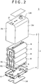
- the battery pack 1 has a housing 2 containing battery cells therein and formed in a substantially rectangular shape, with terminal holes in a front surface thereof.
- the housing 2 has an upper cover 3 and a lower case 4 abuttingly coupled to each other, and a plurality of battery cells 8 composed of lithium ion secondary batteries and a circuit board 9 on which a protective circuit, an SMBus (System Management Bus) controller, an ID resistor and the like are mounted and which is provided with an SMBus line are contained in the housing 2.
- SMBus System Management Bus
- the battery packs 1 are prepared in two kinds, namely, for example, large size battery packs 1a and small size battery packs 1b made to be different from each other in electric capacity according to the number of the battery cells 8 to be contained in the housing 2, and the two kinds of the battery packs 1 are used selectively according to the electronic apparatus for which they are used.
- the large size battery pack 1a contains eight battery cells in two rows and four layers
- the small size battery pack 1b contains four battery cells in two rows and two layers.
- a lower surface 2a is made to be a mount surface which is mounted on a battery mounting portion 5 on the electronic apparatus side, and first to fifth terminal portions 6a to 6e are disposed fronting on a front surface 2b which is continuous with the mount surface.
- Terminals formed at the terminal portions 6a to 6e have respectively predetermined functions; more specifically, the first terminal portion 6a is a positive electrode terminal of the battery pack 1, the second terminal portion 6b is a clock line terminal in the SMBus line, the third terminal portion 6c is a data line terminal in the SMBus line, the fourth terminal portion 6d is an ID terminal connected with an ID resistor, and the fifth terminal portion 6e is a negative electrode terminal of the battery pack 1.
- the battery pack 1 In mounting the battery pack 1 in the electronic apparatus, it is inserted into the battery mounting portion 5 on the electronic apparatus side, with the lower surface 2a as an insertion end, and, after the lower surface 2a comes into abutment on a bottom surface 5a of the battery mounting portion 5, the battery pack 1 is slid toward the side of the front surface 2b, whereby lock recesses 55 and 56 provided in both side surfaces 2c and 2d of the housing 2 are locked by lock protrusions 70 formed in the battery mounting portion 5, resulting in that the battery pack 1 is mounted in the electronic apparatus.
- the battery pack 1 is slid toward the side of a back surface 2e opposite to the front surface 2b of the housing 2, and then the battery pack 1 is pulled up toward the side of an upper surface 2f opposite to the lower surface 2a, whereby the battery pack 1 is detached.
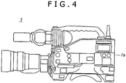
- Examples of the electronic apparatus for which the battery pack 1 is used include a camcorder 7 shown in FIG. 4 .
- the camcorder 7 is one for business use, and is provided with the battery mounting portion 5 at a back surface 7a of a main body thereof.
- the battery mounting portion 5 is so set that only the large size battery pack 1a having a considerable battery capacity can be mounted therein, in view of the use time and frequency of the business-use camcorder 7 and the like factors.
- the battery pack 1 is inserted into the battery mounting portion 5 of the camcorder 7 in the direction of an arrow D in the figure along the right side of a back surface 7a of the camcorder 7, with its lower surface 2a as an insertion end, until it comes to a loading/unloading position where the lower surface 2a abuts on the bottom surface 5a of the battery mounting portion 5.
- the battery pack 1 inserted to the loading/unloading position inside the battery mounting portion 5 is slid in the direction of an arrow S, namely, leftwards in FIG.
- the battery cells 8 are contained in two rows in the battery pack 1, irrespectively of whether the battery pack 1 is the large size battery pack 1a or the small size battery pack 1b; therefore, the area of the lower surface 2a serving as a mount surface for mounting into the battery mounting portion 5 is set substantially the area occupied by two battery cells 8 disposed side by side. Accordingly, even in the camcorder 7 for which the large size battery pack 1a is used, the area of the battery mounting portion 5 need not be so large, and other switches can be arranged at the back surface 7a of the main body of the camcorder 7.
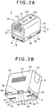
- the housing 2 of the battery pack 1 is formed from a synthetic resin. As shown in FIGS. 1B and 3B , one side surface of the battery pack 1 which is adjacent to the front surface 2b and the back surface 2e and which is directed vertically upwards at the time of mounting the battery pack 1 into the battery mounting portion 5 is provided with an identification portion 10 for identifying gripping surfaces according to the mounting direction. In addition, the front surface 2b and the back surface 2e of the housing 2 are provided with anti-slip portions 11 at positions to be gripped by the user. With the identification portion 10 and the anti-slip portion 11 thus formed, it can be seen if the housing 2 is gripped correctly in mounting the battery pack 1 into the battery mounting portion 5. Besides, the housing 2 can be gripped assuredly even where the housing 2 has an increased weight.
- the battery pack 1 is inserted in such a manner that its lower surface 2a serving as the mount surface is used as the insertion end, and the front surface 2b provided with the terminal portions 6 is slid in a horizontal direction, as above-mentioned. Therefore, it would be necessary for the user to grip the battery pack 1 in the condition where the front surface 2b is directed toward the terminal side in the battery mounting portion 5.
- the identification portion 10 is for permitting the user to discriminate the gripping surfaces of the housing 2 at the time of mounting the battery pack 1 into the battery mounting portion 5.
- the identification portion 10 is formed by a method in which one side surface 2c is provided with a recessed surface portion 10a, the inside of the recessed surface portion 10a is grained, and, further, the recessed surface portion 10a is provided with grains composed of protrusions extending in the front-rear direction.
- the index finger or the middle finger is put on the one side surface 2c so that the identification portion 10 makes contact with the fingertip; as a result, it can be intuitively perceived that the housing 2 is correctly gripped with its one side surface 2c directed vertically upwards, and the sliding direction upon insertion of the housing 2 into the battery mounting portion 5 can also be grasped intuitively.
- the battery pack 1 is the large size battery pack 1a
- a total of eight battery cells 8 are contained in two rows and four layers
- the battery pack 1 is the small size battery pack 1b
- a total of four battery cells 8 are contained in two rows and two layers.
- the large size battery pack 1a is about 550 g in weight
- the small size battery pack 1b is 300 g in weight, heavier than a private-use battery in which battery cells are contained in two rows and one layer. Accordingly, the battery packs should be prevented from slipping down from the user's hand.
- the anti-slip portions 11 formed in the front surface 2b and the back surface 2e are for preventing the slipping-down of the battery pack 1 by making the housing 2 easier to grip by the user's hand at the time of mounting the battery pack 1 into the battery mounting portion 5.
- the anti-slip portions 11 are formed by forming recessed surface portions 11a at upper portions of the front surface 2b and the back surface 2e, and graining the inside of the recessed surface portions 11a.
- the user When gripping the battery pack 1 with the right hand, the user put the thumb on the anti-slip portion 11 in the front surface 2b, and put the middle finger or the third finger and the little finger on the anti-slip portion 11 in the back surface 2e, whereby the rugged surfaces of the anti-slip portions 11 function to give frictional resistance, ensuring that the housing 2 can be held securely without slipping.
- the shape of the grains imparted to the recessed surface portions 11a of the anti-slip portions 11 any of a variety of shapes can be adopted.
- the housing 2 is provided with a grain different from those of the identification portion 10 and the anti-slip portions 11, in other regions than the identification portion 10 and the anti-slip portions 11 of the upper cover 3.
- the lower surface 2a serving as the mount surface for mounting into the battery mounting portion 5 will be described below.
- the lower surface 2a is provided with a pair of insertion guide grooves 15 and 16 which extend along and are spaced from each other along the direction of sliding between the mounting position and the lading/unloading position inside the battery mounting portion 5, and other region than the insertion guide grooves 15 and 16 is used as a region for adhering an identification label 14 (see FIG. 2 ).
- the housing 2 has the lower surface 2a provided with the insertion guide grooves 15 and 16 spaced from each other along the sliding direction, whereby a substantially central portion can be made to be wide, and a side adhering region for the identification label 14 can be secured.
- the lower surface of the housing 2 is not cut up into left and right portions by the insertion guide grooves 15 and 16, as shown in FIG. 2 , a large single identification label 14 formed in a substantially H shape can be adhered.
- the housing 2 has the lower surface 2a provided with the insertion guide grooves 15 and 16 spaced from each other along the sliding direction, as shown in FIG. 7 , that region of the inside surface of the lower surface 2a which is occupied by protrusions present due to the insertion guide grooves 15 and 16 projecting to the inside of the housing 2 can be minimized or at least reduced. Therefore, in the housing 2, a wide electronic part mounting region and a wide patterning region can be secured on the lower surface 2a side of the circuit board 9 disposed on the inside of the lower surface 2a, and efficient use of space can be realized.
- the insertion guide grooves 15 and 16 are formed substantially in the center in the width direction of the lower surface 2a along the front-rear direction.
- the front surface side insertion guide groove 15 formed on the front surface 2b side has an end face fronting on a lower portion of the front surface 2b
- the back surface side insertion guide groove 16 formed on the back surface 2e side has an end face fronting on a lower portion of the back surface 2e and is provided with a lock recess 17 by which a lock piece 35 provided in the battery mounting portion 5 is locked.
- the front surface side insertion guide groove 15 is provided with an L-shaped opening 18 where its insertion end fronting on the front surface 2b is opened in a substantially L shape, and a front surface side guide groove portion 20 continued through a stepped portion 19 formed on the back surface side relative to the L-shaped opening 18. As shown in FIG. 8 , a front surface side guide protrusion 30 formed at the deepest portion in the sliding direction of the battery mounting portion 5 is passed through the front surface side insertion guide groove 15.
- the front surface side guide protrusion 30 is provided with a front surface side protruding bar 32 to be inserted in the front surface side guide groove portion 20, and a lock protrusion 33 substantially L-shaped in section which is formed on the deeper side of the front surface side protruding bar 32 and which is locked by the L-shaped opening 18.
- the front surface side insertion guide groove 15 is so formed that when the housing 2 is inserted to the loading/unloading position in the battery mounting portion 5 and is slid toward the front surface 2b side to the mounting position, the front surface side protruding bar 32 of the front surface side guide protrusion 30 is inserted in the front surface side guide groove portion 20, an end face of the lock protrusion 33 abuts on the stepped portion 19, and the lock protrusion 33 is locked by the L-shaped opening 18.
- the back surface side insertion guide groove 16 is provided with the lock recess 17 for locking the lock piece 35, by forming an end portion fronting on the back surface 2e in a substantially rectangular shape, and with a back surface side guide groove portion 21 formed on the front surface side relative to the lock recess 17.
- the back surface side guide groove portion 21 is formed in line with the front surface side guide groove portion 20.
- the lock recess 17 is formed to be wider than the back surface side guide groove portion 21, and is formed to be continuous with the back surface side guide groove portion 21, whereby a lock wall 22 for locking the lock piece 35 is provided on the front surface side of the housing 2.
- a back surface side guide protrusion 31 formed in the battery mounting portion 5 is inserted into the back surface side insertion guide groove 16, a back surface side guide protrusion 31 formed in the battery mounting portion 5 is inserted.
- the back surface side guide protrusion 31 is provided with a back surface side protruding bar 34 to be passed through the back surface side guide groove portion 21, and the lock piece 35 to be locked by the lock recess 17.
- the back surface side protruding bar 34 is formed in line with the front surface side protruding bar 32.
- the lock piece 35 is inserted in the battery mounting portion 5 through a lock hole 36 opened in the bottom surface 5a of the battery mounting portion 5, as shown in FIG. 8 , whereby its tip portion is brought into abutment on the lock wall 22.
- the lock piece 35 can be turned into and out of the battery mounting portion 5 by a turning mechanism 40.
- the turning mechanism 40 is mounted to a back surface wall of the battery mounting portion 5, and includes a support plate 41 for supporting the lock piece 35, a push bar 42 for pushing the lock piece 35, and an operating button 43 for operating the push bar 42.
- the support plate 41 supports a turning shaft 44 passed through a turning bearing 35a formed at a rear end portion of the lock piece 35.
- the turning shaft 44 is fitted with a coil spring 45 of which one end is locked on the support plate 41 and the other end is locked on the lock piece 35. This ensures that the lock piece 35 is constantly turningly urged by the coil spring 45 in the direction of an arrow L in FIG. 8 so that its tip portion is made to front on the inside of the battery mounting portion 5 through the lock hole 36.
- the push bar 42 for pushing the lock piece 35 is for turning the lock piece 35, which is urged toward the direction of the arrow L, in the direction opposite to the arrow L, and is supported by the support plate 41 so as to be movable up and down between the support plate 41 and a side surface of the battery mounting portion 5.
- the push bar 42 abutting on the lock piece 35 at its one end is provided with an inclined surface portion 42a at its other end opposite to the one end, and the operating button 43 abuts on the inclined surface portion 42a.
- the operating button 43 is for turning the lock piece 35 in the direction opposite to the arrow L by sliding the push bar 42 through pushing the inclined surface portion 42a of the push bar 42.
- the operating button 43 is supported on a side surface of the battery mounting portion 5 by a support member (not shown), and is constantly urged by the coil spring 45 in such a direction that its tip portion is spaced away from the inclined surface portion 42a of the push bar 42.
- the back surface side insertion guide groove 16 is so configured that, when the housing 2 is inserted into the battery mounting portion 5 and is slid toward the front surface 2b side, the back surface side protruding bar 34 is inserted in the back surface side guide groove portion 21, and the lock piece 35 is inserted in the lock recess 17 so as to abut on the lock wall 22 formed between the lock recess 17 and the front surface side guide groove portion 20.
- the housing 2 is guided in the sliding inside the battery mounting portion 5, and is prevented from chattering in a direction orthogonal to the sliding direction. More specifically, with the front surface side guide protrusion 30 inserted in the front surface side insertion guide groove 15 and with the back surface side guide protrusion 31 inserted in the back surface side insertion guide groove 16, the housing 2 is prevented from chattering in the direction of both side surfaces 2c and 2d.
- the housing 2 is prevented from chattering in the direction of both side surfaces 2c and 2d and from chattering in the direction of the upper and lower surfaces 2f and 2a. Therefore, the housing 2 can be secured in reliability of connection to the battery mounting portion 5. Besides, with the L-shaped opening 18 is made to be exposed side by side with the terminal portions 6a to 6e, stresses pertaining to the terminal portions 6a to 6e can be suppressed, and reliability of electrical connection can be secured.
- the lock piece 35 abuts on the lock wall 22, whereby the housing 2 is prevented from sliding in the direction of the back surface 2e, namely, in the direction from the mounting position toward the loading/unloading position, and is prevented from slipping off the battery mounting portion 5 due to vibration, shock or the like.
- the housing 2 is prevented from chattering in the battery mounting portion 5, also by the locking of the lock piece 35 in the lock recess 17.
- the operating button 43 of the turning mechanism 40 is depressed, upon which the tip of the operating button 43 pushes the inclined surface portion 42a of the push bar 42, and the push bar 42 is slid toward the bottom surface 5a side.
- the lock piece 35 pushed by the push bar 42 so as to be urged turningly in the direction opposite to the arrow L, so that the lock piece 35 is retracted from the inside of the battery mounting portion 5, and is disengaged from the lock recess 17 of the housing 2.
- the housing 2 can be slid in the direction of the back surface 2e.
- the back surface side insertion guide groove 16 is provided with the lock recess 17 continuous with the back surface side guide groove portion 21, whereby it is promised that the housing 2 is prevented from chattering in the battery mounting portion 5 and from sliding in the direction of the back surface 2e.
- that region of the lower surface 2a which is occupied by the back surface side insertion guide groove 16 can be reduced, and efficient utilization of the lower surface 2a can be contrived. Therefore, the housing 2 is provided with a wider region for adhering the identification label 14 onto the lower surface 2a, and with an enlarged region for disposing the circuit board 9 on the inside of the lower surface 2a.
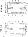
- the housing 2 is provided with a detection recess or recesses 50 for detecting the kind of the battery pack 1, at an edge or edges formed between the lower surface 2a and one or both of the side surfaces 2c and 2d.
- the battery packs 1 prepared are classified into the large size battery packs 1a and the small size battery packs 1b, according to the magnitude of battery capacity.
- the detection recesses 50 are provided respectively in both side surfaces 2c and 2d, as shown in FIG. 6A ; in the small size battery pack 1b, on the other hand, the detection recess 50 is provided only on the side of the other side surface 2d, as shown in FIG. 6B .
- the battery mounting portion 5 is provided with mis-insertion preventive engaging protrusions 51 corresponding to the detection recess 50, on side surfaces opposed to the side surfaces 2c and 2d. With such engaging protrusions 51 projectingly provided, mis-mounting of a battery pack of a non-compatible size can be obviated.
- the large size battery pack 1a is provided with a pair of the detection recesses 50 in both side surfaces 2c and 2d
- the battery mounting portion 5 of an electronic apparatus corresponding to the large size battery pack 1a is provided with a pair of the engaging protrusions 51 for engagement with both detection recesses, whereby the small size battery pack 1b provided with the detection recess 50 only in the other side surface 2d can be prevented from being erroneously mounted into the battery mounting portion 5 in consideration.
- the engaging protrusion 51 projectingly provided on the side surface opposite to the other side surface 2d of the small size battery pack 1b interferes with the edge formed between the other side surface 2d and the lower surface 2a of the housing 2, whereby the small size battery pack 1b is prevented from being mounted into the battery mounting portion 5.
- the power consumption is large and, therefore, only the large size battery pack 1a having a great battery capacity can be mounted.
- the L side battery packs 1a may be business-use batteries with comparatively large size and capacity
- the small size battery packs 1b may be private-use batteries with comparatively small size and capacity.
- a system may be adopted in which only the large size battery packs 1a can be mounted in the electronic apparatuses for business use, while both size battery packs 1a and 1b can be mounted in electronic apparatuses for private use.
- the housing 2 is provided with the detection recess(es) 50 not in the front surface 2b where a type discriminating rugged pattern has generally been provided, but at the edge(s) formed between the lower surface 2a and one or both of the side surfaces 2c and 2d. This ensures that the housing 2 can be securely provided in its front surface 2b with a space where five terminal portions 6 and an end face of the front surface side insertion guide groove 15 are frontingly provided side by side.
- the battery mounting portion 5 may have a configuration in which type discriminating switches 52 corresponding to the detection recesses 50 are projectingly provided on side surfaces opposed to both side surfaces 2c and 2d of the housing 2, in place of the engaging protrusions 51.
- type discriminating switches 52 corresponding to the detection recesses 50 are projectingly provided on side surfaces opposed to both side surfaces 2c and 2d of the housing 2, in place of the engaging protrusions 51.
- lock recesses 55 and 56 formed on both sides of the detection recess 50 in the housing 2 and operative to lock the housing 2 in the battery mounting portion 5 will be described below.
- the lock recesses 55 and 56 are formed on both sides of the detection recess 50 at each of the edges formed between the lower surface 2a and the side surfaces 2c and 2d.
- the lock recesses 55 and 56 ensure that when the housing 2 is inserted into the battery mounting portion 5 and is slid to the mounting position, lock protrusions 70 projectingly provided on side surfaces of the battery mounting portion 5 correspondingly to the lock recesses 55 and 56 are locked.
- the front surface side lock recess 55 provided on the side of the front surface 2b of the housing 2 includes an inclined surface portion 57 for drawing in the lock protrusion 70, a clamped portion 58 to be clamped between the lock protrusion 70 and the bottom surface 5a of the battery mounting portion 5, and an orthogonal surface portion 59 continuous with the inclined surface portion 57 and extended in the height direction substantially orthogonal to the lower surface 2a.
- the front surface side lock recess 55 is provided with an opening 60 through which the lock protrusion 70 is put into and out of a clamped state between the inclined surface portion 57 and the clamped portion 58.
- the back surface side lock recess 56 provided on the side of the back surface 2e of the housing 2 includes an inclined surface portion 61 for drawing in the lock protrusion 70, a clamped portion 62 to be clamped between the lock protrusion 70 and the bottom surface 5a of the battery mounting portion 5.
- the back surface side lock recess 56 is provided with an opening 63 through which the lock protrusion 70 is put into and out of a clamped state between the inclined surface portion 61 and the clamped portion 62.
- Each of the lock protrusions 70 to be locked at the front surface side lock recess 55 and the back surface side lock recess 56 includes a base portion 71 provided erectingly from the bottom surface 5a of the battery mounting portion 5, and a lock portion 72 extended from the base portion 71 toward the back surface side of the battery mounting portion 5 and located at upper surfaces of the clamped portions 58 and 62.
- the lock portion 72 is so configured that its distance from the bottom surface 5a of the battery mounting portion 5 is roughly equal to or slightly smaller than the thickness of the clamped portions 58 and 62 of the housing 2 of which the lower surface 2a is mounted on the bottom surface 5a of the battery mounting portion 5.
- the clamped portions 58 and 62 are each pressed into the gap between the lock portion 72 and the bottom surface 5a of the battery mounting portion 5, so as to hold the clamped portions 58 and 62, thereby locking the housing 2 in the battery mounting portion 5.
- the lock portions 72 of the lock protrusions 70 go forward through the openings 60 and 63.
- the inclined surface portions 57 and 61 and the orthogonal surface portion 59 of the housing 2 slide on the lock protrusions 70, whereby the lock portions 72 are made to be at the same height as the upper surfaces of the clamped portions 58 and 62 and are guided to such positions as to permit mutual locking.
- the detection recess 50 is also made to go forward toward the engaging protrusion 51 projectingly provided on the side wall of the battery mounting portion 5.
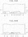
- the housing 2 is slid in the direction of an arrow S in FIG. 9 , namely, toward the side of the front surface 2b.
- terminal pins 101 on the side of the battery mounting portion 5 are inserted into and engaged with the terminal portions 6 made to front on the front surface 2b, and the clamped portions 58 and 62 of the lock recesses 55 and 56 come to be clamped between the lock portions 72 of the lock protrusions 70 and the bottom surface 5a of the battery mounting portion 5.
- the lock portions 72 it suffices for the lock portions 72 to be capable of clamping the clamped portions 58 and 62 between themselves and the bottom surface 5a of the battery mounting portion 5, and they may not necessarily be clamped between the upper surfaces of the clamped portions 58 and 62 and the ceiling surfaces of the lock recesses 55 and 56 opposed to the upper surfaces. Therefore, a configuration may be adopted in which the lock portions 72 do not have a thickness and that gaps are left between the lock portions 72 and the ceiling surfaces of the lock recesses 55 and 56. It is to be noted here that, naturally, the lock portions 72 may be clamped between the upper surfaces of the clamped portions 58 and 62 and the ceiling surfaces of the lock recesses 55 and 56.
- the housing 2 is slid in the direction opposite to the arrow S in FIG. 9 from the mounting position to the loading/unloading position, whereby the clamped portions 58 and 62 are drawn out of the gaps between the lock portions 72 and the bottom surface 5a of the battery mounting portion 5.
- the lock portions 72 of the lock protrusions 70 are located in the openings 60 and 63 of the lock recesses 55 and 56, so that the housing 2 can be moved in the direction opposite to the arrow D, namely, in the direction toward the side of the upper surface 2f.
- the front surface side lock recess 55 is provided with the orthogonal surface portion 59 continuous with the inclined surface portion 57 and orthogonal to the lower surface 2a.
- the circuit board 9 is disposed on the inside of the housing 2. In the housing 2, the circuit board 9 is disposed at a height where the inclined surface portion 57 and the orthogonal surface portion 59 meet each other.
- the circuit board 9 can be held on the inside of the orthogonal surface portion 59 at the height of the meeting point between the inclined surface portion 57 and the orthogonal surface portion 59, whereby the circuit board 9 can be disposed at the height at which the front surface side lock recess 55 is formed.
- the region for arranging the battery cells 8 connected to the circuit board 9 are also disposed more on the upper side, which leads to an increase in the size of the housing 2 and, on the other hand, generates a dead space between the circuit board 9 and the lower surface 2a.
- the housing 2 has a configuration in which an increase in the size of the lock recesses 55 and 56 is contrived and the orthogonal surface portion 59 is provided to thereby arrange the circuit board 9 on the inside of the orthogonal surface portion 59, the height at which to dispose the circuit board 9 can be set closer to the lower surface 2a, and the housing 2 can be prevented from becoming larger in size.
- the circuit board 9 can be held at the height of the meeting point between the inclined surface portion 57 and the orthogonal surface portion 59, and an increase in the size of the lock recesses 55 and 56 can be attained while maintaining the area and the arranging position of the circuit board 9.
- the orthogonal surface portion may be formed not only in the front surface side lock recess 55 but also in the back surface side lock recess 56.
- the lock recesses 55 and 56 have the clamped portions 58 and 62 formed to have a thickness larger than the depth of the detection recess 50 in the height direction orthogonal to the lower surface 2a. This can prevent the lock protrusion 70 from being erroneously inserted into the detection recess 50 in putting the housing 2 in position.
- the lock protrusion 70 might be erroneously inserted into the detection recess 50.
- a configuration in which the depth of the detection recess 50 is smaller than the thickness of the clamped portions 58 and 62 ensures that the housing 2 cannot be inserted to the loading/unloading position where its lower surface 2a abuts on the bottom surface 5a of the battery mounting portion 5 and that an inclination of the housing 2 or the like abnormality is found, which permits the user to recognize that appropriate insertion has not been made.
- the housing 2 can be inserted to the loading/unloading position where its lower surface 2a abuts on the bottom surface 5a of the battery mounting portion 5 even in the case where the lock protrusion 70 is erroneously inserted into the detection recess 50.
- the lock portions 72 of the lock protrusions 70 are necessary only to be capable of clamping the clamped portions 58 and 62 and may not necessarily be thick, and, therefore, they can be formed in a suppressed thickness.
- the housing 2 can be inserted to the bottom surface 5a of the battery mounting portion 5 while the lock protrusion 70 is kept erroneously inserted in the detection recess 50.
- the thickness of the clamped portions 58 and 62 is set to be larger than the depth of the detection recess 50, so that if the lock protrusion 70 is erroneously inserted in the detection recess 50, the housing 2 cannot be inserted to the bottom surface 5a of the battery mounting portion 5. Accordingly, the user can easily discriminate whether or not the housing 2 is erroneously inserted in the battery mounting portion 5.
- the housing 2 has a configuration in which the depth of the detection recess 50 in the width direction of the lower surface 2a, i.e., the depth of the detection recess(es) 50 in the lower surface 2a from the side surface (s) 2c and 2d in the direction orthogonal to the direction of sliding of the housing 2 between the loading/unloading position and the mounting position, is set to be larger than the depth of the front surface side lock recess 55 and the back surface side lock recess 56 in the same direction.
- the detection recess 50 is for engagement with the engaging protrusion 51 projectingly provided on the side wall of the battery mounting portion 5.
- both side surfaces 2c and 2d of the housing 2 are each provided with the detection recess 50, whereas in the small size battery pack 1b, only the other side surface 2d of the housing 2 is provided with the detection recess 50.
- the engaging protrusion 51 for engagement with the detection recess 50 is projectingly provided at each of those side surfaces of the battery mounting portion 5 of the electronic apparatus used with the large size battery pack 1a which face the side surfaces 2c and 2d of the housing 2; on the other hand, the detection recess 50 is projectingly provided only at that side surface of the battery mounting portion 5 of the electronic apparatus used with the small size battery pack 1b which faces the other side surface 2d of the housing 2.
- Each of these engaging protrusions 51 is so formed that its protrusion amount from the side surface of the battery mounting portion 5 is roughly equal to the depth of the detection recess 50 in the width direction of the lower surface 2a. Therefore, when the engaging protrusion 51 is inserted in the detection recess 50, it is substantially entirely engaged in the detection recess 50. In addition, if a non-compatible small size battery pack 1b is about to be inserted in the battery mounting portion 5, the engaging protrusion 51 abuts on that one side surface 2c of the housing 2 which is not provided with the detection recess 50, whereby insertion of the non-compatible small size battery pack 1b into the battery mounting portion 5 is prevented.
- the protrusion amount of the engaging protrusion 51 is set to be approximately equal to the depth of the detection recess 50 in the width direction of the lower surface 2a, and the depth of the detection recess 50 is set to be larger than the depth of the lock recesses 55 and 56 in the same direction.
- the engaging protrusion 51 is formed to protrude by an amount larger than the depth of the lock recesses 55 and 56.
- the lock protrusions 70 are formed to have a protrusion amount according to the depth of the lock recesses 55 and 56 in the width direction of the lower surface 2a. Accordingly, the engaging protrusion 51 is formed to have a protrusion amount larger than that of the lock protrusion 70.
- the engaging protrusion 51 protruding from a side surface of the battery mounting portion 5 abuts on one side surface 2c of the housing 2.
- the engaging protrusion 51 is formed to have a protrusion amount larger than that of the lock protrusions 70, the lock protrusions 70 are also not inserted into the lock recesses 55 and 56. Since none of the engaging protrusion 51 and the lock protrusions 70 is engaged with the detection recess 50 and the lock recesses 55 and 56, the housing 2 cannot be mounted into the battery mounting portion 5.
- the housing 2 is not held by the battery mounting portion 5 even if it is being inserted, and it is difficult to slide the housing 2 toward the side of the front surface 2b. Therefore, the user can easily judge that the small size battery pack 1b is being erroneously inserted into the electronic apparatus for exclusive use with the large size battery pack 1a.
- the engaging protrusion 51 on the battery mounting portion 5 side is also formed to have a protrusion amount smaller than that of the lock protrusions 70. Therefore, as shown in FIG. 11B , where the small size battery pack 1b is mounted in the battery mounting portion 5 of an electronic apparatus for exclusive use with the large size battery pack 1a, the lock protrusions 70 would be inserted into the lock recesses 55 and 56 even if the engaging protrusion 51 abuts on the one side surface 2c. Accordingly, it is difficult for the user to judge that erroneous insertion of the battery pack 1 is occurring, and might irrationally slide the housing 2 toward the front surface 2b side so as to mount the housing 2 into the battery mounting portion 5.
- the detection recess 50 is formed to be deeper than the lock recesses 55 and 56, so that the engaging protrusion 51 is also protruding more than the lock protrusions 70, and, when the engaging protrusion 51 abuts on the one side surface 2c, the lock protrusions 70 are also prevented from being inserted into the lock recesses 55 and 56. This ensures that, in the case of the battery pack 1, erroneous mounting of the small size battery pack 1b into the electronic apparatus for exclusive use with the large size battery pack 1a can be prevented.
- the terminal portion 6 includes a terminal hole 80 which is formed in the lower case 4 of the housing 2 and is made to front on the outer side of the front surface 2b, and a metallic bearing 82 which is fitted in a terminal case 81 disposed on the inside of the terminal hole 80 and in which the terminal pin 101 formed on the battery mounting portion 5 side is inserted.
- the terminal hole 80 includes a recessed surface portion 84 provided with an insertion hole 83 in which the terminal pin 101 is inserted, and a guide portion 85 which is formed at the inner peripheral surface of the insertion hole 83 and which is continuous with the recessed surface portion 84 and the metallic bearing 82.
- the recessed surface portion 84 is a roughly rectangularly shaped recess formed in the front surface 2b of the housing 2, and a roughly central portion of the bottom surface thereof is opened in a circular shape to form the insertion hole 83 in which the terminal pin 101 is to be inserted.
- the guide portion 85 includes an inclined surface portion 86 which is formed at the inner peripheral surface of the insertion hole 83 and which guides the terminal pin 101 into the metallic bearing 82, and a support surface portion 87 which is formed to be substantially equal to the metallic bearing 82 in diameter and which supports the terminal pin 101 together with the metallic bearing 82.
- the insertion hole 83 opened in the recessed surface portion 84 has an upper end opened to be larger in diameter than the terminal pin 101, so that the terminal pin 101 is easily inserted therein. Besides, the insertion hole 83 permits the terminal pin 101 to be inserted into the terminal portion 6 without any load thereon, through a process wherein the terminal pin 101 is guided through the inclined surface portion 86 formed on the upper end side of the insertion hole 83 into the support surface portion 87 which is formed to be roughly equal to the metallic bearing 82 in diameter and which is continuous with the metallic bearing 82.
- the metallic bearing 82 disposed in continuity with the support surface portion 87 is a hollow cylindrical metallic member of which one end in the longitudinal direction is opened and the other end is closed.
- the metallic bearing 82 is fitted in the terminal case 81, and is connected on its closed end side through a metallic tab 88 to the circuit board 9 connected with the terminal case 81 (see FIG. 17B ).
- the metallic bearing 82 is so configured that the terminal case 81 is disposed inside the lower case 4 together with the circuit board 9, whereby it is made to be continuous with the support surface portion 87 of the terminal hole 80 as shown in FIG. 12 , for insertion and holding of the terminal pin 101 inserted in the insertion hole 83.
- the terminal case 81 in which to fit the metallic bearing 82 is a roughly rectangularly shaped resin part formed to have a length in the longitudinal direction roughly equal to the length in the width direction of the lower case 4.
- the terminal case 81 is provided with fitting holes 89 for containing the metallic bearings 82 along the longitudinal direction thereof.
- the fitting hole 89 has a hollow cylindrical shape with an inside diameter roughly equal to the outer shape of the metallic bearing 82, and is opened at both ends in the longitudinal direction thereof.
- Each metallic bearing 82 is continued to the terminal hole 80 via an end face of the fitting hole 89, and is connected to the metallic tab 88.
- the insertion hole 83 is opened inside the recessed surface portion 84 of the terminal hole 80, and is continued to the metallic bearing 82 through the guide portion 85, whereby the metallic bearing 82 is located on the inner side of the housing 2 relative to the front surface 2b.
- the terminal pin 101 is inserted and held in the support surface portion 87 of the guide portion 85 of the terminal hole 80 and the metallic bearing 82 fitted in the terminal case 81.
- the terminal pin 101 thus inserted and held in two component parts, namely, the terminal hole 80 on the lower case 4 side and the terminal case 81 disposed inside the lower case 4, even when a vibration is applied to the electronic apparatus at the time of mounting the battery pack 1, the load exerted on the terminal pin 101 can be lessened, and reliability of electrical connection can be maintained.
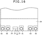
- the terminal portions 6 include first to fifth terminal portions 6a to 6e arrayed at a lower portion of the front surface 2b.
- the first and second terminal portions 6a and 6b and the fourth and fifth terminal portions 6d and 6e are formed symmetrically on left and right sides at the front surface 2b of the housing 2, and the third terminal portion 6c is formed at a position deviated from the center of the front surface 2b toward the side of the fourth and fifth terminal portions 6d and 6e.
- an end face of the above-mentioned front surface side insertion guide groove 15 is made to front on the center of the front surface 2b.
- the terminals formed at the terminal portions 6a to 6e have respectively predetermined functions.
- the first terminal portion 6a is a positive electrode terminal of the battery pack 1
- the second terminal portion 6b is a clock line terminal in the SMBus line
- the third terminal portion 6c is a data line terminal in the SMBus line
- the fourth terminal portion 6d is an ID terminal with an ID resistance connected thereto
- the fifth terminal portion 6e is a negative electrode terminal of the battery pack 1.
- the housing 2 In using the battery pack 1, the housing 2 is inserted into the battery mounting portion 5 and is slid toward the front surface 2b side, whereby the terminal pins 101 disposed on the battery mounting portion 5 side are inserted into and held in the terminal portions 6a to 6e.
- electric power can be supplied through the first and fifth terminal portions 6a and 6e; clock data can be communicated through the second terminal portion 6b; a variety of data such as residual battery capacity, fully charged capacity, present charged capacity, the possible serviceable time from now on under the present use condition, number of charge-discharge cycles, etc. and ID data indicating that the battery pack 1 is a genuine product, and so on can be communicated through the third terminal portion 6c; and the ID resistance can be detected through the fourth terminal portion 6d.
- the ID resistance detected through the fourth terminal portion 6d is used for detecting, on the electronic apparatus side, which of a plurality of types of battery packs prepared according to the difference(s) in capacity has been mounted; specifically, different resistances are set correspondingly to the large size battery packs 1a and the small size battery packs 1b.
- the terminal pin 101 is inserted into the fourth terminal portion 6d, the resistance on the battery pack 1 side is measured, on the electronic apparatus side, and it is judged which of the different types of battery packs 1 has been mounted.
- the fourth terminal portion 6d is formed proximate to the fifth terminal portion 6e which constitutes the negative electrode terminal. It is based on the fact that, if the ID detecting resistor and the negative electrode line are remote from each other, electromagnetic radiation from signal lines or the like therebetween is propagated as noise, possibly hampering accurate measurement of resistance. Therefore, in the battery pack 1, with the fourth terminal portion 6d arranged proximate to the negative electrode terminal 6e, the distance between the ID resistor and the negative electrode line can be designed to be short, accurate measurement of resistance can be achieved.
- the third terminal portion 6c is formed at a position deviated from the center in the width direction of the front surface 2b of the housing 2 toward either of the left and right sides, in this embodiment, toward the side of the fourth and fifth terminal portions 6d and 6e, in view of the presence of the front surface side insertion guide groove 15 in a substantially central position in the width direction of the front surface 2b.
- the terminal portions 6a to 6e are arranged at irregular intervals, and the terminal pins 101 formed on the battery mounting portion 5 side correspondingly to the terminal portions 6a to 6e are also arranged at irregular intervals, accordingly. Therefore, when the battery pack 1 is inappropriately in a left-right reversed state, the terminal pins 101 cannot be inserted into the terminal portions, so that the battery pack 1 can be prevented from being erroneously inserted into the battery mounting portion 5 in the left-right reversed state.
- a pair of electrode tabs 91 connected to the electrodes of the battery cells 8 are extended so as not to overlap with any of the third and fourth terminal portions 6c and 6d.
- the electrode tabs 91 connected to the electrodes of the battery cells 8 are formed to be narrower on the side of tip portions 91a thereof.
- the tip portions 91a of the electrode tabs 91 are extended in positions which are located between the second terminal portion 6b and the third terminal portion 6c and between the third terminal portion 6c and the fourth terminal portion 6d and which are not on the same plane as the terminal portions 6a to 6e.
- FIG. 17A is a front view showing the battery cells 8 disposed on the circuit board 9 connected to a terminal case 81
- FIG. 17B is a bottom view of the same condition as viewed from the back side of the circuit board 9.
- the electrode tab 91 is bent from an end portion of the battery cell 8 into the direction of the arrow F along the circuit board 9, whereby the narrower tip portion 91a thereof is laid around so as not to overlap with any of the second to fourth terminal portions 6b to 6d. Therefore, in the battery pack 1, it is possible to prevent electromagnetic radiations due to the electrode tabs 91 from being propagated as noise to the communication lines, and accurate data communication can be carried out.
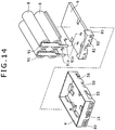
- the battery mounting portion 5 having the terminal pins 101 to be inserted in the terminal portions 6a to 6e will be described below.
- the battery mounting portion 5 includes a terminal board 100 having the terminal pins 101 to be inserted in the terminal portions 6 fronting on the front surface 2b of the housing 2, a containing case 102 which contains the housing 2 therein and in which the terminal board 100 is fitted, and a support plate 103 for supporting the terminal board 100 fitted in the containing case 102.
- the terminal board 100 has a roughly rectangular overall shape, and on the side of its one surface 104 fronting on the inside of the containing case 102, the terminal pins 101 are projectingly provided correspondingly to the number and intervals of the terminal portions 6 provided on the battery pack 1 side.
- the base end side is supported by a support recess (not shown) provided in the terminal board 100, and the tip is directed toward the side of a front surface 100a of the terminal board 100 which faces the front surface 2b of the housing 2.
- each of the terminal pins 101 is connected to a terminal cord passed through the support recess.
- each terminal cord is led out to the exterior of the containing case 102 through a lead-out recess 105 formed on the side of a back surface 100b of the terminal board 100.
- the above-mentioned front surface side guide protrusion 30 is formed adjacently to the terminal pins 101.
- the front surface side guide protrusion 30 is inserted in the front surface side insertion guide groove 15 formed in the lower surface 2a of the housing 2, so as thereby to guide the loading and unloading of the housing 2 into and from the battery mounting portion 5 and to prevent the housing 2 from chattering in the direction of both side surfaces 2c and 2d and the direction of the upper and lower surfaces 2f and 2a when the housing 2 is mounted in the battery mounting portion 5.
- the front surface side guide protrusion 30 is provided with the front surface side protruding bar 32 and the lock protrusion 33.
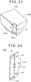
- a shielding plate 106 for protecting the terminal pins 101 is turnably mounted onto the one surface 104 of the terminal board 100.
- the shielding plate 106 is provided for preventing the terminal pins 101 from contact with a conductor, breakage or the like by being exposed to the exterior in the case where the battery pack 1 is not mounted, and is an elongate plate member disposed on the one surface 104 along the array direction of the terminal pins 101.
- the shielding plate 106 is supported to be turnable, with the back surface 100b side as a fulcrum.
- the shielding plate 106 is locked to a coil spring (not shown), whereby it is normally biased for turning in such a direction as to shield the terminal pins 101.
- the shielding plate 106 shields the terminal pins 101 from the exterior, and when the battery pack 1 is mounted, the shielding plate 106 is pushed by the front surface 2b of the housing 2 and turned toward the side of the back surface 100b, thereby exposing the terminal pins 101.
- the terminal board 100 is provided in its bottom surface 100c with support recesses 108 brought into contact with support protrusions 112 of the support plate 103.
- the terminal board 100 is supported on the support protrusions 112 of the support plate 103, with some clearance therebetween, whereby it is supported to be swingable in the direction of the bottom surface 100c.
- the terminal board 100 is provided on its bottom surface 100c with a lock piece 109 to be locked on the bottom surface 102c of the containing case 102.
- the containing case 102 in which to contain the terminal board 100 as above is formed to be slightly larger than the housing 2 of the battery pack 1, and has a roughly rectangular box-like shape opened on the upper side where the housing 2 is loaded and unloaded.
- the containing case 102 is projectingly provided with the above-mentioned lock protrusions 70 and the above-mentioned engaging protrusion 51 on its side walls 102a and 102b which respectively face the side surfaces 2c and 2d of the housing 2.
- the turning mechanism 40 for turning the lock piece 35 engaged with the lower surface 2a of the housing 2 is disposed at the back wall, facing the back surface 2e of the housing 2, of the containing case 102.
- the containing case 102 is provided in its bottom surface 102c (which constitutes the bottom surface 5a of the battery mounting portion 5) and both side walls 102a and 102b with a fitting hole 110 in which to fit the terminal board 100.
- the fitting hole 110 has its bottom surface 102c opened in a roughly rectangular shape, and has its side walls 102a and 102b each opened also in a rectangular shape so as to be continuous with the opening in the bottom surface 102c.
- the terminal board 100 is inserted into the containing case 102 through the bottom surface 102c, and its bottom surface 100c is supported on both sides thereof by the side walls 102a and 102b of the containing case 102, whereby the terminal board 100 is fitted in the fitting hole 110.
- the lock piece 109 of the terminal board 100 is locked on the bottom surface 102c of the containing case 102.
- the one surface 104 provided with the terminal pins 101 is made to front on the inside of the containing case 102.
- the terminal board 100 is fitted in the fitting hole 110, it is supported on the bottom surface 100c side thereof by the support plate 103.
- the support plate 103 is a resin part formed in a roughly rectangular plate-like shape, and is attached to the bottom surface 102c of the containing case 102 in a cantilever manner, thereby supporting the terminal board 100 in the fitting hole 110.
- the support plate 103 is provided, on its surface facing the terminal board 100, with support protrusions 112 to be brought into contact with the support recesses 108 of the terminal board 100.
- the support plate 103 is provided with an opening 113, correspondingly to the lock piece 109 of the terminal board 100, and is provided with a plurality of attaching holes 114 for attachment to the bottom surface 102c of the containing case 102.
- the support plate 103 is attached to the containing case 102 from the upper side of the terminal board 100, thereby to support the terminal board 100.
- the support recesses 108 are formed to be wider than the support protrusions 112, and none of the side walls of the support recesses 108 makes contact with the support protrusions 112.
- the fitting hole 110 is opened on the sides of the side surfaces 102a and 102b of the containing case 102. Therefore, the terminal board 100 can be swung in the direction of an arrow X in FIG. 19 .
- the swinging range of the terminal board 100 in the direction of the arrow X is restricted by the contact of one of the side walls of the support recesses 108 with the support protrusion 112 or by the contact of the lock piece 109 with the opening 113.
- support plate 103 is so formed as to leave some clearance between the tip surface of the support protrusion 112 and the bottom surface of the support recess 108.
- the support plate 103 is supported on the containing case 102 in a cantilever manner, and has some flexibility. Therefore, the terminal board 100 can be swung also in the direction of an arrow Z in FIG. 19 .
- the swinging range of the terminal board 100 in the direction of the arrow Z is restricted by the contact of the bottom surfaces of the support recesses 108 with the tip surfaces of the support protrusions 112 or by the support thereof in the fitting hole 110 formed in the side walls 102a and 102b of the containing case 102.
- the containing case 102 is formed as a resin part.
- the containing case 102 is provided with the fitting hole 110 also in its front wall 102d, facing the back surface 100b of the terminal board 100, and its side walls 102a and 102b, whereby the front end of the containing case 102 is made to be a free end and to have some flexibility. Therefore, the terminal board 100 can be swung also in the direction of an arrow Y in FIG. 19 . The swinging range of the terminal board 100 is restricted by the flexing range of the front wall 102d of the containing case 102.
- the battery pack 1 is so formed that the terminal board 100 can be swung in three directions, namely, in the directions of the arrows X, Y and Z in FIG. 19 .
- This ensures that even when the battery pack 1 mounted in the battery mounting portion 5 is swung due to swinging of the electronic apparatus main body, the terminal board 100 is swung following up to the battery pack 1, keeping the terminal portions 6 and the terminal pins 101 in connection with each other. Therefore, generation of gap at contact points between the terminal portions 6 and the terminal pins 101 is obviated, whereby failure in connection can be prevented.
- sliding is prevented from occurring between the terminal portions 6 and the terminal pins 101, so that these parts can be prevented from being broken or deteriorated.
- the terminal board 100 can be swung in the direction of the arrow X in FIG. 19 , since both the side walls 102a and 102b of the containing case 102 are opened. Therefore, where the battery pack 1 is mounted in the battery mounting portion 5 of the camcorder 7, the terminal board 100 can be swung in the vertical direction in which the camcorder 7 is frequently swung. Accordingly, even if the battery pack 1 is swung in the vertical direction in use of the camcorder 7, the reliability of connection between the terminal portions 6 of the battery pack 1 and the terminal pins 101 of the battery mounting portion 5 would not be spoiled.
- the battery mounting portion 5 is not limited to the configuration in which the containing case 102 is used for fitting the terminal board 100 and the support plate 103 therein.
- a configuration may be adopted in which a battery containing portion is formed in the main body of the electronic apparatus, and the terminal board 100 and the support plate 103 are fitted in the battery containing portion.
- the battery pack 1 Since the battery pack 1 is planned to be used in a business-use camcorder 7, the battery pack 1 is designed to have an increased battery capacity and to be capable of being used for a prolonged time.
- the business-use camcorder 7 when used, a plurality of spare battery packs 1 are prepared, and when one battery has run down, it is replaced with another, and shooting is continued. In this case, the residual capacities (residual charges) of the spare battery packs 1 are confirmed, whereby it is possible to select a spare battery pack with more residual capacity and to discriminate unused battery packs from the exhausted battery pack(s) 1.
- the battery pack 1 has such a residual capacity display unit 120 formed on the upper surface 2f of the housing 2.
- the residual capacity display unit 120 includes display windows 121 to be turned ON for indicating the residual capacity of the battery pack 1, a residual capacity display switch 122 for turning ON the display window(s) 121, detecting means 123 for detecting the depressed state of the residual capacity display switch 122, and control means 124 for controlling the ON/OFF conditions of the display windows 121 according to the results of detection by the detecting means 123.
- the residual capacity display unit 120 changes over the ON/OFF conditions of the display windows 121 according to the time for which the residual capacity display switch 122 is depressed, whereby the convenience in use by the user is enhanced.
- the display windows 121 have LEDs incorporated therein, and the LEDs are individually turned ON or OFF according to the residual battery capacity. As shown in FIG. 24 , for example, four display windows 121 are provided side by side at the upper surface 2f of the housing 2, and the ON/OFF conditions of the LEDs at the display windows 121 are controlled as follows. When the residual battery capacity (absolute residual capacity ratio) is less than 20%, all the four LEDs are turned OFF; when the residual capacity is 20 to 39%, only the left end LED is turned ON; when the residual capacity is 40 to 59%, the two left-side LEDs are turned ON; when the residual capacity is 60 to 79%, the three left-side LEDs are turned ON; and when the residual capacity is 80 to 100%, all the four LEDs are turned ON.
- the residual battery capacity absolute residual capacity ratio
- the residual capacity display switch 122 is formed at the upper surface 2f of the housing 2, adjacently to the display windows 121.
- the time for which the residual capacity display switch 122 has been depressed by the user is detected by the detecting means 123.
- the control means 124 controls the ON time of the LEDs in the display windows 121, according to the time for which the residual capacity display switch 122 has been depressed. For example, when the time for which the residual capacity display switch 122 has been depressed is 0.5 second or less, the display window(s) 121 are turned ON for 1 second; and when the time for which the residual capacity display switch 122 has been depressed is more than 0.5 second, the display window(s) 121 are turned ON for 5 second.
- the detecting means 123 for detecting the time for which the residual capacity display switch 122 has been depressed and the control means 124 for controlling the ON time of the display windows 121 are provided on a circuit board (see FIG. 2 ) disposed on the upper surface 2f side in the inside of the housing 2, or on the circuit board 9 connected to this circuit board through a flexible wiring board.
- the control means 124 monitors the ON/OFF states of the LEDs (step S1). Where all the LEDs are OFF, the control means 124 determines whether or not the residual capacity display switch 122 has been depressed (step S2). Where the residual capacity display switch 122 has not been depressed, the control means 124 again monitors the ON/OFF states of the LEDs, and where the residual capacity display switch 122 has been depressed, the control means 124 determines whether or not the residual capacity ratio of the battery pack 1 is less than 20% (step S3).
- the control means 124 keeps all the LEDs in the OFF state, and where the residual capacity ratio is 20% or more, the control means 124 turns ON the display window(s) 121 according to the residual capacity ratio, followed by returning to the monitoring of the ON/OFF states of the LEDs (step S4).
- step S1 When it is found in step S1 that the LED(s) at the display window(s) 121 is ON, the control means 124 determines whether or not the residual capacity display switch 122 has been depressed for 0.5 second or less (step S5). Then, where the time for which the residual capacity display switch 122 has been depressed is 0.5 second or less, the control means 124 determines whether or not the LED ON condition has continued for 1 second (step S6). Where the LED ON condition has not continued for 1 second, the control means 124 maintain the ON state of the LED(s), and where the LED ON condition has continued for 1 second or above, the control means 124 turns OFF the LED(s), followed by returning to the monitoring of the ON/OFF states of the LEDs (step S7).
- step S5 When it is found in step S5 that the residual capacity display switch 122 has been depressed for more than 0.5 second, the control means 124 determines whether or not the LED ON condition at the display window (s) 121 has continued for 5 second (step S8). Where the LED ON condition has not continued for 5 second, the control means 124 maintains the LED ON condition, and where the LED ON condition has continued for 5 second, the control means 124 turns OFF the LED(s), followed by returning to the monitoring of the ON/OFF states of the LEDs (step S9).
- the ON time of the display window(s) 121 differs depending on the time for which the residual capacity display switch 122 is depressed.
- the plurality of spare battery packs 1 may be arranged in a row, and the residual capacity display switch 122 may sequentially be depressed for a long time so as to turn ON the display window(s) 121 for 5 second or more, whereby the residual capacity ratios can be confirmed efficiently.
- the time for which the residual capacity display switch 122 is depressed for the purpose of prolonging the ON time of the display window(s) 121 is not limited to 0.5 second but may be changed, as required.
- the ON time of the display window (s) 121 prolonged when the residual capacity display switch 122 is depressed for a long time is not limited to 5 second but may be changed, as required.
- the change made in the ON/OFF state of the display window(s) 121 when the residual capacity display switch 122 is depressed for a long time is not limited to the prolonging of the ON time but may, for example, be an increase in the luminance of the LED(s) in the display window(s) 121.
- the luminance of the LED(s) in the display window(s) 121 is enhanced, it is possible to enhance the visibility of the display windows 121 in a light environment, such as outdoors in daytime.
- the change made in the ON/OFF state of the display window(s) 121 when the residual capacity display switch 122 is depressed for a long time is not limited to the prolonging of the ON time but may, for example, be blinking of the LED(s) in the display window(s) 121, whereby it is also made possible to enhance the visibility of the display windows 121.
- the control means 124 may blink the LEDs in the display windows 121 also when the residual capacity display switch 122 is not depressed for a long time, which also enhances the visibility of the display windows 121.
- the operation of the residual capacity display unit 120 is not limited to the four-stage display of the display windows 121 but may be set otherwise, as required. Furthermore, where the residual battery capacity is less than 20%, the color(s) of the LED(s) in the ON state or blinking state may be changed so as to make a display in four stages (20 to 15%, 15 to 10%, 10 to 5%, and below 5%).
Claims (5)
- Bloc-batterie comprenant des première à cinquième parties de borne disposées séquentiellement sur une première surface latérale d'un boîtier,
dans lequel parmi lesdites parties de borne, ladite première partie de borne formée sur un premier côté d'extrémité de ladite première surface latérale est une borne d'électrode positive, ladite cinquième partie de borne formée sur l'autre côté d'extrémité de ladite première surface latérale est une borne d'électrode négative, ladite quatrième partie de borne formée de façon adjacente à ladite cinquième partie de borne est une borne ID pour l'identification dudit bloc-batterie, et ladite quatrième partie de borne et ladite cinquième partie de borne sont proches l'une de l'autre ; et
une partie de guidage destinée à guider le chargement et le déchargement dudit bloc-batterie dans et depuis une partie de montage de batterie est formée sensiblement au centre de ladite première surface latérale en alignement avec lesdites parties de borne, et ladite troisième partie de borne disposée de façon centrale est formée à une position écartée vers ledit premier côté d'extrémité ou ledit autre côté d'extrémité. - Bloc-batterie selon la revendication 1, dans lequel ladite deuxième partie de borne adjacente à ladite première partie de borne est proche de ladite première partie de borne.
- Bloc-batterie selon la revendication 2, dans lequel lesdites première et deuxième parties de borne et lesdites quatrième et cinquième parties de borne sont formées en symétrie gauche-droite sur ladite première surface latérale.
- Bloc-batterie selon la revendication 1, dans lequel une paire de languettes d'électrode reliées à des électrodes d'éléments de batterie sont prolongées entre ladite deuxième partie de borne et ladite troisième partie de borne et entre ladite troisième partie de borne et ladite quatrième partie de borne et à des positions qui ne sont pas situées sur le même plan que lesdites parties de borne.
- Bloc-batterie selon la revendication 4, dans lequel lesdites parties de prolongement desdites languettes d'électrode sont formées pour être plus petites en largeur que des parties de connexion reliées auxdites électrodes desdits éléments de batterie.
Priority Applications (3)
| Application Number | Priority Date | Filing Date | Title |
|---|---|---|---|
| EP16183810.7A EP3121866B1 (fr) | 2007-03-30 | 2008-03-10 | Bloc-batteries |
| EP23152177.4A EP4220814A3 (fr) | 2007-03-30 | 2008-03-10 | Bloc-batterie |
| EP16183819.8A EP3118909B1 (fr) | 2007-03-30 | 2008-03-10 | Bloc-batteries |
Applications Claiming Priority (6)
| Application Number | Priority Date | Filing Date | Title |
|---|---|---|---|
| JP2007095321A JP4428393B2 (ja) | 2007-03-30 | 2007-03-30 | バッテリパック |
| JP2007095324A JP4479742B2 (ja) | 2007-03-30 | 2007-03-30 | バッテリパック |
| JP2007095322A JP4897544B2 (ja) | 2007-03-30 | 2007-03-30 | バッテリパック |
| JP2007095323A JP4600415B2 (ja) | 2007-03-30 | 2007-03-30 | バッテリパック |
| JP2007095327A JP4640368B2 (ja) | 2007-03-30 | 2007-03-30 | バッテリパック |
| JP2007095331A JP4927624B2 (ja) | 2007-03-30 | 2007-03-30 | バッテリパック |
Related Child Applications (5)
| Application Number | Title | Priority Date | Filing Date |
|---|---|---|---|
| EP23152177.4A Division EP4220814A3 (fr) | 2007-03-30 | 2008-03-10 | Bloc-batterie |
| EP16183819.8A Division EP3118909B1 (fr) | 2007-03-30 | 2008-03-10 | Bloc-batteries |
| EP16183819.8A Division-Into EP3118909B1 (fr) | 2007-03-30 | 2008-03-10 | Bloc-batteries |
| EP16183810.7A Division EP3121866B1 (fr) | 2007-03-30 | 2008-03-10 | Bloc-batteries |
| EP16183810.7A Division-Into EP3121866B1 (fr) | 2007-03-30 | 2008-03-10 | Bloc-batteries |
Publications (3)
| Publication Number | Publication Date |
|---|---|
| EP1978578A2 EP1978578A2 (fr) | 2008-10-08 |
| EP1978578A3 EP1978578A3 (fr) | 2014-11-19 |
| EP1978578B1 true EP1978578B1 (fr) | 2018-02-21 |
Family
ID=39535623
Family Applications (4)
| Application Number | Title | Priority Date | Filing Date |
|---|---|---|---|
| EP16183819.8A Active EP3118909B1 (fr) | 2007-03-30 | 2008-03-10 | Bloc-batteries |
| EP16183810.7A Active EP3121866B1 (fr) | 2007-03-30 | 2008-03-10 | Bloc-batteries |
| EP23152177.4A Pending EP4220814A3 (fr) | 2007-03-30 | 2008-03-10 | Bloc-batterie |
| EP08250802.9A Active EP1978578B1 (fr) | 2007-03-30 | 2008-03-10 | Bloc-batteries |
Family Applications Before (3)
| Application Number | Title | Priority Date | Filing Date |
|---|---|---|---|
| EP16183819.8A Active EP3118909B1 (fr) | 2007-03-30 | 2008-03-10 | Bloc-batteries |
| EP16183810.7A Active EP3121866B1 (fr) | 2007-03-30 | 2008-03-10 | Bloc-batteries |
| EP23152177.4A Pending EP4220814A3 (fr) | 2007-03-30 | 2008-03-10 | Bloc-batterie |
Country Status (1)
| Country | Link |
|---|---|
| EP (4) | EP3118909B1 (fr) |
Families Citing this family (6)
| Publication number | Priority date | Publication date | Assignee | Title |
|---|---|---|---|---|
| CN101950428A (zh) * | 2010-09-28 | 2011-01-19 | 中国科学院软件研究所 | 一种基于地形高程值的纹理合成方法 |
| US20130164567A1 (en) | 2011-06-24 | 2013-06-27 | Seektech, Inc. | Modular battery pack apparatus, systems, and methods |
| WO2012178205A2 (fr) * | 2011-06-24 | 2012-12-27 | Mark Olsson | Appareil, systèmes et procédés de bloc de batteries modulaire |
| CN108973720B (zh) * | 2018-07-12 | 2020-08-21 | 北京车和家信息技术有限公司 | 电池管理的方法及装置 |
| CN210403800U (zh) | 2019-01-09 | 2020-04-24 | 比亚迪股份有限公司 | 单体电池、动力电池包及电动车 |
| CN113644373B (zh) * | 2021-10-14 | 2022-02-08 | 深圳市德兰明海科技有限公司 | 一种电池模组及储能电源 |
Family Cites Families (25)
| Publication number | Priority date | Publication date | Assignee | Title |
|---|---|---|---|---|
| JP3237144B2 (ja) | 1991-10-11 | 2001-12-10 | ソニー株式会社 | 残量表示付きバッテリーケース |
| JP3416962B2 (ja) * | 1992-09-18 | 2003-06-16 | ソニー株式会社 | バッテリーパック |
| JP3575646B2 (ja) * | 1995-12-06 | 2004-10-13 | ソニー株式会社 | バツテリーパツク |
| JPH09243718A (ja) | 1996-03-08 | 1997-09-19 | Sony Corp | バッテリパック及びバッテリ状態の表示方法 |
| JPH10144195A (ja) | 1996-11-05 | 1998-05-29 | Harness Sogo Gijutsu Kenkyusho:Kk | リレー駆動回路 |
| JP3223883B2 (ja) | 1998-06-15 | 2001-10-29 | ソニー株式会社 | バッテリパック |
| JP4110656B2 (ja) * | 1999-02-17 | 2008-07-02 | ソニー株式会社 | バッテリーパック、バッテリー装着装置、電力供給装置及び電子機器 |
| JP4110657B2 (ja) * | 1999-02-17 | 2008-07-02 | ソニー株式会社 | バッテリーパック、バッテリー装着装置、電力供給装置及び電子機器 |
| JP3507786B2 (ja) | 2000-10-19 | 2004-03-15 | 三洋ジ−エスソフトエナジー株式会社 | 電池パック |
| JP4123516B2 (ja) * | 2003-12-26 | 2008-07-23 | ソニー株式会社 | バッテリー装置 |
| JP5191625B2 (ja) * | 2004-11-29 | 2013-05-08 | 京セラ株式会社 | バッテリー及び電子機器 |
| JP2006228471A (ja) | 2005-02-15 | 2006-08-31 | Sony Corp | 電子機器のバッテリーロック機構 |
| JP4462112B2 (ja) * | 2005-05-26 | 2010-05-12 | パナソニック電工株式会社 | 電動工具 |
| JP2007095324A (ja) | 2005-09-27 | 2007-04-12 | Hitachi Displays Ltd | 有機el表示パネルの製造方法、及びこの製造方法により製造した有機el表示パネル |
| JP4725996B2 (ja) | 2005-09-27 | 2011-07-13 | 株式会社アイペックス | コネクタ装置 |
| JP4624896B2 (ja) | 2005-09-27 | 2011-02-02 | 三菱製紙株式会社 | 導電性材料前駆体 |
| JP2007095321A (ja) | 2005-09-27 | 2007-04-12 | Hitachi Ltd | 画像表示装置 |
| JP2007095327A (ja) | 2005-09-27 | 2007-04-12 | Orc Mfg Co Ltd | ショートアーク型放電灯 |
| JP2007095322A (ja) | 2005-09-27 | 2007-04-12 | Auto Network Gijutsu Kenkyusho:Kk | 同軸ケーブルおよびシールドワイヤハーネス |
| JP4479742B2 (ja) | 2007-03-30 | 2010-06-09 | ソニー株式会社 | バッテリパック |
| JP4600415B2 (ja) | 2007-03-30 | 2010-12-15 | ソニー株式会社 | バッテリパック |
| JP4897544B2 (ja) | 2007-03-30 | 2012-03-14 | ソニー株式会社 | バッテリパック |
| JP4927624B2 (ja) | 2007-03-30 | 2012-05-09 | ソニー株式会社 | バッテリパック |
| JP4428393B2 (ja) | 2007-03-30 | 2010-03-10 | ソニー株式会社 | バッテリパック |
| JP4640368B2 (ja) | 2007-03-30 | 2011-03-02 | ソニー株式会社 | バッテリパック |
-
2008
- 2008-03-10 EP EP16183819.8A patent/EP3118909B1/fr active Active
- 2008-03-10 EP EP16183810.7A patent/EP3121866B1/fr active Active
- 2008-03-10 EP EP23152177.4A patent/EP4220814A3/fr active Pending
- 2008-03-10 EP EP08250802.9A patent/EP1978578B1/fr active Active
Non-Patent Citations (1)
| Title |
|---|
| None * |
Also Published As
| Publication number | Publication date |
|---|---|
| EP4220814A2 (fr) | 2023-08-02 |
| EP3118909B1 (fr) | 2024-02-21 |
| EP3118909A1 (fr) | 2017-01-18 |
| EP1978578A2 (fr) | 2008-10-08 |
| EP3121866A1 (fr) | 2017-01-25 |
| EP1978578A3 (fr) | 2014-11-19 |
| EP4220814A3 (fr) | 2023-11-15 |
| EP3121866B1 (fr) | 2023-05-17 |
Similar Documents
| Publication | Publication Date | Title |
|---|---|---|
| US20200303692A1 (en) | Battery pack | |
| US8486550B2 (en) | Battery pack | |
| US8389141B2 (en) | Battery pack | |
| EP1978578B1 (fr) | Bloc-batteries | |
| CN202839784U (zh) | 电池组 | |
| US8728645B2 (en) | Battery pack | |
| US8603657B2 (en) | Battery pack | |
| US8637175B2 (en) | Battery pack having a detection groove | |
| JP4927624B2 (ja) | バッテリパック | |
| JP4428393B2 (ja) | バッテリパック | |
| JP4640368B2 (ja) | バッテリパック | |
| JP4897544B2 (ja) | バッテリパック | |
| JP4479742B2 (ja) | バッテリパック |
Legal Events
| Date | Code | Title | Description |
|---|---|---|---|
| PUAI | Public reference made under article 153(3) epc to a published international application that has entered the european phase |
Free format text: ORIGINAL CODE: 0009012 |
|
| AK | Designated contracting states |
Kind code of ref document: A2 Designated state(s): AT BE BG CH CY CZ DE DK EE ES FI FR GB GR HR HU IE IS IT LI LT LU LV MC MT NL NO PL PT RO SE SI SK TR |
|
| AX | Request for extension of the european patent |
Extension state: AL BA MK RS |
|
| RIC1 | Information provided on ipc code assigned before grant |
Ipc: H01M 2/00 20060101AFI20140401BHEP |
|
| PUAL | Search report despatched |
Free format text: ORIGINAL CODE: 0009013 |
|
| AK | Designated contracting states |
Kind code of ref document: A3 Designated state(s): AT BE BG CH CY CZ DE DK EE ES FI FR GB GR HR HU IE IS IT LI LT LU LV MC MT NL NO PL PT RO SE SI SK TR |
|
| AX | Request for extension of the european patent |
Extension state: AL BA MK RS |
|
| RIC1 | Information provided on ipc code assigned before grant |
Ipc: H01M 2/00 20060101AFI20141014BHEP |
|
| 17P | Request for examination filed |
Effective date: 20150519 |
|
| RBV | Designated contracting states (corrected) |
Designated state(s): AT BE BG CH CY CZ DE DK EE ES FI FR GB GR HR HU IE IS IT LI LT LU LV MC MT NL NO PL PT RO SE SI SK TR |
|
| AKX | Designation fees paid |
Designated state(s): DE FR GB |
|
| AXX | Extension fees paid |
Extension state: MK Extension state: BA Extension state: AL Extension state: RS |
|
| GRAP | Despatch of communication of intention to grant a patent |
Free format text: ORIGINAL CODE: EPIDOSNIGR1 |
|
| STAA | Information on the status of an ep patent application or granted ep patent |
Free format text: STATUS: GRANT OF PATENT IS INTENDED |
|
| INTG | Intention to grant announced |
Effective date: 20170821 |
|
| GRAS | Grant fee paid |
Free format text: ORIGINAL CODE: EPIDOSNIGR3 |
|
| GRAA | (expected) grant |
Free format text: ORIGINAL CODE: 0009210 |
|
| STAA | Information on the status of an ep patent application or granted ep patent |
Free format text: STATUS: THE PATENT HAS BEEN GRANTED |
|
| AK | Designated contracting states |
Kind code of ref document: B1 Designated state(s): DE FR GB |
|
| REG | Reference to a national code |
Ref country code: GB Ref legal event code: FG4D |
|
| REG | Reference to a national code |
Ref country code: DE Ref legal event code: R096 Ref document number: 602008054075 Country of ref document: DE |
|
| REG | Reference to a national code |
Ref country code: FR Ref legal event code: PLFP Year of fee payment: 11 |
|
| REG | Reference to a national code |
Ref country code: DE Ref legal event code: R097 Ref document number: 602008054075 Country of ref document: DE |
|
| PLBE | No opposition filed within time limit |
Free format text: ORIGINAL CODE: 0009261 |
|
| STAA | Information on the status of an ep patent application or granted ep patent |
Free format text: STATUS: NO OPPOSITION FILED WITHIN TIME LIMIT |
|
| 26N | No opposition filed |
Effective date: 20181122 |
|
| REG | Reference to a national code |
Ref country code: DE Ref legal event code: R079 Ref document number: 602008054075 Country of ref document: DE Free format text: PREVIOUS MAIN CLASS: H01M0002000000 Ipc: H01M0050000000 |
|
| PGFP | Annual fee paid to national office [announced via postgrant information from national office to epo] |
Ref country code: FR Payment date: 20230222 Year of fee payment: 16 |
|
| PGFP | Annual fee paid to national office [announced via postgrant information from national office to epo] |
Ref country code: GB Payment date: 20230222 Year of fee payment: 16 Ref country code: DE Payment date: 20230221 Year of fee payment: 16 |
|
| P01 | Opt-out of the competence of the unified patent court (upc) registered |
Effective date: 20230527 |