EP1978279A2 - Fahrzeugsteuerungssystem - Google Patents
Fahrzeugsteuerungssystem Download PDFInfo
- Publication number
- EP1978279A2 EP1978279A2 EP08006687A EP08006687A EP1978279A2 EP 1978279 A2 EP1978279 A2 EP 1978279A2 EP 08006687 A EP08006687 A EP 08006687A EP 08006687 A EP08006687 A EP 08006687A EP 1978279 A2 EP1978279 A2 EP 1978279A2
- Authority
- EP
- European Patent Office
- Prior art keywords
- vibration
- vehicle
- vibrations
- vibration model
- tire
- Prior art date
- Legal status (The legal status is an assumption and is not a legal conclusion. Google has not performed a legal analysis and makes no representation as to the accuracy of the status listed.)
- Granted
Links
- 230000008878 coupling Effects 0.000 claims abstract description 50
- 238000012937 correction Methods 0.000 claims description 98
- 230000033001 locomotion Effects 0.000 claims description 36
- 238000013459 approach Methods 0.000 claims description 8
- 238000002485 combustion reaction Methods 0.000 claims description 6
- 230000014509 gene expression Effects 0.000 description 84
- 238000006073 displacement reaction Methods 0.000 description 81
- 238000005096 rolling process Methods 0.000 description 76
- 238000010168 coupling process Methods 0.000 description 41
- 238000005859 coupling reaction Methods 0.000 description 41
- 238000010586 diagram Methods 0.000 description 26
- 238000006243 chemical reaction Methods 0.000 description 24
- 239000000725 suspension Substances 0.000 description 20
- 230000001629 suppression Effects 0.000 description 19
- 230000005540 biological transmission Effects 0.000 description 18
- 238000004364 calculation method Methods 0.000 description 16
- 238000002955 isolation Methods 0.000 description 15
- 238000004088 simulation Methods 0.000 description 14
- 238000013523 data management Methods 0.000 description 12
- 230000000644 propagated effect Effects 0.000 description 9
- 230000005484 gravity Effects 0.000 description 8
- 239000000446 fuel Substances 0.000 description 6
- 238000006557 surface reaction Methods 0.000 description 6
- 230000005489 elastic deformation Effects 0.000 description 3
- 238000004891 communication Methods 0.000 description 2
- 238000002347 injection Methods 0.000 description 2
- 239000007924 injection Substances 0.000 description 2
- 230000001133 acceleration Effects 0.000 description 1
- 230000003044 adaptive effect Effects 0.000 description 1
- 230000006399 behavior Effects 0.000 description 1
- 230000015572 biosynthetic process Effects 0.000 description 1
- 230000003247 decreasing effect Effects 0.000 description 1
- 230000006866 deterioration Effects 0.000 description 1
- 238000010248 power generation Methods 0.000 description 1
- 238000012545 processing Methods 0.000 description 1
- 238000012546 transfer Methods 0.000 description 1
Images


Classifications
-
- F—MECHANICAL ENGINEERING; LIGHTING; HEATING; WEAPONS; BLASTING
- F16—ENGINEERING ELEMENTS AND UNITS; GENERAL MEASURES FOR PRODUCING AND MAINTAINING EFFECTIVE FUNCTIONING OF MACHINES OR INSTALLATIONS; THERMAL INSULATION IN GENERAL
- F16F—SPRINGS; SHOCK-ABSORBERS; MEANS FOR DAMPING VIBRATION
- F16F15/00—Suppression of vibrations in systems; Means or arrangements for avoiding or reducing out-of-balance forces, e.g. due to motion
- F16F15/02—Suppression of vibrations of non-rotating, e.g. reciprocating systems; Suppression of vibrations of rotating systems by use of members not moving with the rotating systems
-
- B—PERFORMING OPERATIONS; TRANSPORTING
- B60—VEHICLES IN GENERAL
- B60C—VEHICLE TYRES; TYRE INFLATION; TYRE CHANGING; CONNECTING VALVES TO INFLATABLE ELASTIC BODIES IN GENERAL; DEVICES OR ARRANGEMENTS RELATED TO TYRES
- B60C99/00—Subject matter not provided for in other groups of this subclass
- B60C99/006—Computer aided tyre design or simulation
-
- B—PERFORMING OPERATIONS; TRANSPORTING
- B60—VEHICLES IN GENERAL
- B60T—VEHICLE BRAKE CONTROL SYSTEMS OR PARTS THEREOF; BRAKE CONTROL SYSTEMS OR PARTS THEREOF, IN GENERAL; ARRANGEMENT OF BRAKING ELEMENTS ON VEHICLES IN GENERAL; PORTABLE DEVICES FOR PREVENTING UNWANTED MOVEMENT OF VEHICLES; VEHICLE MODIFICATIONS TO FACILITATE COOLING OF BRAKES
- B60T8/00—Arrangements for adjusting wheel-braking force to meet varying vehicular or ground-surface conditions, e.g. limiting or varying distribution of braking force
- B60T8/17—Using electrical or electronic regulation means to control braking
- B60T8/173—Eliminating or reducing the effect of unwanted signals, e.g. due to vibrations or electrical noise
-
- B—PERFORMING OPERATIONS; TRANSPORTING
- B60—VEHICLES IN GENERAL
- B60W—CONJOINT CONTROL OF VEHICLE SUB-UNITS OF DIFFERENT TYPE OR DIFFERENT FUNCTION; CONTROL SYSTEMS SPECIALLY ADAPTED FOR HYBRID VEHICLES; ROAD VEHICLE DRIVE CONTROL SYSTEMS FOR PURPOSES NOT RELATED TO THE CONTROL OF A PARTICULAR SUB-UNIT
- B60W10/00—Conjoint control of vehicle sub-units of different type or different function
- B60W10/04—Conjoint control of vehicle sub-units of different type or different function including control of propulsion units
- B60W10/06—Conjoint control of vehicle sub-units of different type or different function including control of propulsion units including control of combustion engines
-
- B—PERFORMING OPERATIONS; TRANSPORTING
- B60—VEHICLES IN GENERAL
- B60W—CONJOINT CONTROL OF VEHICLE SUB-UNITS OF DIFFERENT TYPE OR DIFFERENT FUNCTION; CONTROL SYSTEMS SPECIALLY ADAPTED FOR HYBRID VEHICLES; ROAD VEHICLE DRIVE CONTROL SYSTEMS FOR PURPOSES NOT RELATED TO THE CONTROL OF A PARTICULAR SUB-UNIT
- B60W10/00—Conjoint control of vehicle sub-units of different type or different function
- B60W10/04—Conjoint control of vehicle sub-units of different type or different function including control of propulsion units
- B60W10/08—Conjoint control of vehicle sub-units of different type or different function including control of propulsion units including control of electric propulsion units, e.g. motors or generators
-
- B—PERFORMING OPERATIONS; TRANSPORTING
- B60—VEHICLES IN GENERAL
- B60W—CONJOINT CONTROL OF VEHICLE SUB-UNITS OF DIFFERENT TYPE OR DIFFERENT FUNCTION; CONTROL SYSTEMS SPECIALLY ADAPTED FOR HYBRID VEHICLES; ROAD VEHICLE DRIVE CONTROL SYSTEMS FOR PURPOSES NOT RELATED TO THE CONTROL OF A PARTICULAR SUB-UNIT
- B60W10/00—Conjoint control of vehicle sub-units of different type or different function
- B60W10/18—Conjoint control of vehicle sub-units of different type or different function including control of braking systems
- B60W10/184—Conjoint control of vehicle sub-units of different type or different function including control of braking systems with wheel brakes
-
- B—PERFORMING OPERATIONS; TRANSPORTING
- B60—VEHICLES IN GENERAL
- B60W—CONJOINT CONTROL OF VEHICLE SUB-UNITS OF DIFFERENT TYPE OR DIFFERENT FUNCTION; CONTROL SYSTEMS SPECIALLY ADAPTED FOR HYBRID VEHICLES; ROAD VEHICLE DRIVE CONTROL SYSTEMS FOR PURPOSES NOT RELATED TO THE CONTROL OF A PARTICULAR SUB-UNIT
- B60W30/00—Purposes of road vehicle drive control systems not related to the control of a particular sub-unit, e.g. of systems using conjoint control of vehicle sub-units
- B60W30/02—Control of vehicle driving stability
- B60W30/025—Control of vehicle driving stability related to comfort of drivers or passengers
-
- B—PERFORMING OPERATIONS; TRANSPORTING
- B60—VEHICLES IN GENERAL
- B60W—CONJOINT CONTROL OF VEHICLE SUB-UNITS OF DIFFERENT TYPE OR DIFFERENT FUNCTION; CONTROL SYSTEMS SPECIALLY ADAPTED FOR HYBRID VEHICLES; ROAD VEHICLE DRIVE CONTROL SYSTEMS FOR PURPOSES NOT RELATED TO THE CONTROL OF A PARTICULAR SUB-UNIT
- B60W30/00—Purposes of road vehicle drive control systems not related to the control of a particular sub-unit, e.g. of systems using conjoint control of vehicle sub-units
- B60W30/02—Control of vehicle driving stability
- B60W30/04—Control of vehicle driving stability related to roll-over prevention
-
- B—PERFORMING OPERATIONS; TRANSPORTING
- B60—VEHICLES IN GENERAL
- B60W—CONJOINT CONTROL OF VEHICLE SUB-UNITS OF DIFFERENT TYPE OR DIFFERENT FUNCTION; CONTROL SYSTEMS SPECIALLY ADAPTED FOR HYBRID VEHICLES; ROAD VEHICLE DRIVE CONTROL SYSTEMS FOR PURPOSES NOT RELATED TO THE CONTROL OF A PARTICULAR SUB-UNIT
- B60W30/00—Purposes of road vehicle drive control systems not related to the control of a particular sub-unit, e.g. of systems using conjoint control of vehicle sub-units
- B60W30/18—Propelling the vehicle
- B60W30/20—Reducing vibrations in the driveline
-
- B—PERFORMING OPERATIONS; TRANSPORTING
- B60—VEHICLES IN GENERAL
- B60T—VEHICLE BRAKE CONTROL SYSTEMS OR PARTS THEREOF; BRAKE CONTROL SYSTEMS OR PARTS THEREOF, IN GENERAL; ARRANGEMENT OF BRAKING ELEMENTS ON VEHICLES IN GENERAL; PORTABLE DEVICES FOR PREVENTING UNWANTED MOVEMENT OF VEHICLES; VEHICLE MODIFICATIONS TO FACILITATE COOLING OF BRAKES
- B60T2260/00—Interaction of vehicle brake system with other systems
- B60T2260/08—Coordination of integrated systems
-
- B—PERFORMING OPERATIONS; TRANSPORTING
- B60—VEHICLES IN GENERAL
- B60T—VEHICLE BRAKE CONTROL SYSTEMS OR PARTS THEREOF; BRAKE CONTROL SYSTEMS OR PARTS THEREOF, IN GENERAL; ARRANGEMENT OF BRAKING ELEMENTS ON VEHICLES IN GENERAL; PORTABLE DEVICES FOR PREVENTING UNWANTED MOVEMENT OF VEHICLES; VEHICLE MODIFICATIONS TO FACILITATE COOLING OF BRAKES
- B60T2270/00—Further aspects of brake control systems not otherwise provided for
- B60T2270/86—Optimizing braking by using ESP vehicle or tire model
-
- B—PERFORMING OPERATIONS; TRANSPORTING
- B60—VEHICLES IN GENERAL
- B60W—CONJOINT CONTROL OF VEHICLE SUB-UNITS OF DIFFERENT TYPE OR DIFFERENT FUNCTION; CONTROL SYSTEMS SPECIALLY ADAPTED FOR HYBRID VEHICLES; ROAD VEHICLE DRIVE CONTROL SYSTEMS FOR PURPOSES NOT RELATED TO THE CONTROL OF A PARTICULAR SUB-UNIT
- B60W50/00—Details of control systems for road vehicle drive control not related to the control of a particular sub-unit, e.g. process diagnostic or vehicle driver interfaces
- B60W2050/0001—Details of the control system
- B60W2050/0019—Control system elements or transfer functions
- B60W2050/0028—Mathematical models, e.g. for simulation
- B60W2050/0031—Mathematical model of the vehicle
- B60W2050/0036—Multiple-track, 3D multi-body vehicle model, e.g. combination of models for vehicle sub-units
Definitions
- the present invention relates to a vehicle control system that suppresses vibrations which occur at various portions of a vehicle.
- US 2005/0049761 JP 2004-168148A discloses a vehicle control system that is capable of suppressing the vibrations of a vehicle body.
- the vehicle control system corrects an input instruction so as to suppress the vibrations of the vehicle by a motion model.
- the motion model is formed by a dynamic model of the vibrations of tires of the vehicle, the vehicle body unsprung vibrations in suspensions, and the vehicle body sprung vibration which are received by the vehicle body per se, which occurs according to an input instruction corresponding to at least one of accelerator operation, steering operation, and brake operation which are conducted by an occupant.
- the above vehicle control system uses vehicle vibration models including a vehicle body sprung vibration model, a suspension vibration model and a tire vibration model.
- the vehicle vibration model is separated and hierarchized into the vehicle body sprung vibration model, the suspension vibration model, and the tire vibration model, thereby making it possible to express the respective vibration models as lower-order linear models.
- hierarchization means formation of hierarchical structure in up-down or front-rear transfer of vibration caused by a tire. For this reason, the capacity of storing the vehicle vibration model can be reduced, and the calculation load can be reduced in execution of the estimated calculation of the vibrations that are generated in the respective portions of the vehicle using the vehicle vibration model.
- a force that propagates in the longitudinal direction of the vehicle occurs in a driving wheel rotating shaft.
- the translational forces of the driving wheels are internally propagated to a driven wheel (rolling wheel) side through a chassis to generate the translational force at the driven wheel rotating shaft.
- the translational force that is exerted on the driving wheel rotating shaft from the driving wheel affects the motion state of the driven wheels.
- the tire vibration model and the suspension vibration model are separated from each other, it is impossible to deal with the force that is internally propagated to the driven wheel side from the driving wheel side.
- the present invention has therefore an object to provide a vehicle control system which is capable of suppressing vibrations that occur at various portions of a vehicle by a vehicle vibration model that enables the vibration state of tires to be estimated with a high precision with a vehicle vibration model being separated into a vehicle body vibration model (sprung vibration model), a chassis vibration model (unsprung vibration model), and a tire vibration model.
- a vehicle vibration model being separated into a vehicle body vibration model (sprung vibration model), a chassis vibration model (unsprung vibration model), and a tire vibration model.
- a vehicle control system comprises a control unit that stores a vehicle vibration model, and an operation device that is controllable by the control unit and operative to change a motion state of the vehicle.
- the vehicle vibration model is separated into a vehicle body vibration model, a chassis vibration model, and a tire vibration model to estimate vibration states at respective portions of a vehicle.
- the control unit receives an input parameter to be input to the vehicle vibration model, calculates estimated vibration states of the respective portions of the vehicle, and calculates control quantities according to the vibration states to control the operation device.
- the tire vibration model in the vehicle vibration model includes vibration models of front wheel tires, rear wheel tires and a virtual coupling element that virtually couples the front wheel tires and the rear wheel tires with each other.
- a vehicle control system is mainly made up of a control device (engine/drive system ECU) 10 of an engine and drive system (engine/drive system).
- the engine/drive system ECU 10 communicates with another ECU such as a brake system ECU and a power steering ECU (not shown) on an in-vehicle LAN (not shown), which is a communication network disposed within a vehicle.
- the engine/drive system ECU 10 includes a data management unit 11.
- the data management unit 11 includes a communication interface function that manages a transmit/receive of data using the above in-vehicle LAN.
- the data management unit 11 also includes a calculation function that calculates an estimated drive torque which is an input parameter necessary for simulating the vibrations that occur in an actual vehicle in a vehicle vibration model that will be described later, based on various sensor signals that are loaded through a sensor input signal processing unit 16.
- the data management unit 11 calculates an estimated net drive torque of driving wheels in transmitting the drive torque generated by the engine to the driving wheels through a power transmission system including a transmission based on the wheel velocities of the respective wheels, the rotational speed of the engine, the rotational speed of a driving shaft, and the rotational speed ratio of an input shaft and an output shaft in the transmission.
- the estimated drive torque that is calculated by the data management unit 11 is input to a vibration suppression control function unit 12 that stores a vehicle vibration model therein. Also, the data management unit 11 receives travel resistance data of the respective wheels (four wheels) that is a parameter to be input to the vehicle vibration model from, for example, the brake system ECU, and then outputs the received travel resistance data to the vibration suppression control function unit 12. The data management unit 11 detects a signal for calculating the travel resistance of the respective wheels, or receives the signal from another ECU, and calculates the travel resistances of the respective wheels in the data management unit 11.
- the data management unit 11 receives steering angle data from, for example, the power steering ECU, and calculates a reaction force in a lateral (right-left) direction which is exerted on the front wheels from a road surface when the vehicle turns, based on the steering angle to output the calculated reaction force to the vibration suppression control function unit 12.
- the calculation function of the reaction force in the lateral direction can be provided in, for example, the power steering ECU, so that the data management unit 11 receives the calculated reaction force in the lateral direction.
- the travel resistance data of the respective vehicles represents the travel resistances in the vehicle longitudinal direction which are exerted on the respective wheels from the road surface as reaction forces.
- the travel resistance data is calculated based on the wheel velocities of the respective vehicles which are detected by vehicle velocity sensors that are disposed in the respective wheels.
- the travel resistance not only changes due to the state of the road surface per se (irregularity, slope, friction coefficient, etc.), but also changes due to the braking force or a cornering drag. In any factor, when the travel resistance changes, the rotating velocity of the wheels slightly changes according to the changed travel resistance. Accordingly, it is possible to calculate the travel resistance in the wheel longitudinal direction based on the change ratio of the respective wheel velocities with time (angular velocity).
- the vibration suppression control function unit 12 estimates the motion states of the respective portions in the vehicle, and also calculates a correction control quantity (drive torque correction quantity) for suppressing the vibrations that occur at the respective portions of the vehicle based on the estimated results to output the correction control quantity to the drive system device control unit 13.
- the conceptual structural diagram of the vibration suppression control function unit 12 is shown in Fig. 2 .
- the estimated drive torque, the estimated four wheel travel resistances, and the lateral road surface reaction force are input to a vehicle vibration model 12a.
- the vehicle vibration model 12a calculates the motion states of the respective portions in the vehicle (vibrations that occur at the respective portions) as the internal state based on those inputs.
- the internal state quantity is output to a controller 12b, and the controller 12b multiplies the internal state quantity by a given feedback gain Ks to calculate the drive torque correction quantity for suppressing the vibrations of the respective portions.
- the drive system device control unit 13 calculates the drive torque to be generated in the drive shaft mainly according to an accelerator operation of a driver based on the accelerator operation of the driver (pedal depression quantity, pedal depression velocity), the travel velocity of the vehicle, and a gear ratio of the transmission in the vehicle.
- an accelerator operation of a driver based on the accelerator operation of the driver (pedal depression quantity, pedal depression velocity), the travel velocity of the vehicle, and a gear ratio of the transmission in the vehicle.
- TRC traction control system
- VSC vehicle stability control system
- ACC adaptive cruse control system
- the drive system device control unit 13 corrects the basic drive torque according to the above drive torque correction quantity to calculate a final target drive torque to be generated in the drive shaft.
- the drive system device control unit 13 calculates a target generation torque of the engine so as to generate the calculated target drive torque.
- the drive system device control unit 13 calculates the appropriate combination of the target gear ratio in the transmission with the target generation torque in the engine for generating the target drive torque.
- the target gear ratio is output to a transmission control device (not shown), and the target generation torque is output to the engine system operation device control unit 14.
- the engine system operation device control unit 14 calculates the control quantities and the control timings of the respective operation devices (throttle valve, fuel injection device, ignition coil, etc.) which are required to generate the target generation torque by the engine. More specifically, the engine system operation device control unit 14 calculates the air quantity to be supplied in the engine, required fuel quantity to be supplied, and ignition timing. A combustion mode that depends on the various operating states and the limit condition such as the target air-fuel ratio are met by controlling the air, the fuel, and the ignition. Then, the air system device operation quantity, the fuel system device operation quantity, and the ignition system device operation timing are calculated according to the respective required values of the air, the fuel, and the ignition system to output the calculated values to the drive instruction output unit 15 shown in Fig. 1 . The drive instruction output unit 15 outputs the drive signal to the corresponding operation device 17 according to the input operation quantity and the operation timing.
- the respective operation devices throttle valve, fuel injection device, ignition coil, etc.
- the target generation torque that is determined taking the drive torque correction quantity for suppressing the vibrations of the vehicle body into consideration is given to the engine system operation device control unit 14.
- the engine system operation device control unit 14 is entrusted with the operation quantity of the respective operation devices for generating the target generation torque.
- the engine system operation device control unit 14 can use not only an operation device that directly adjusts the operating state of the engine but also an operation device that is driven by the engine to indirectly control the operation of the engine.
- a power generation load in an alternator that is driven by the engine can be actively operated to control the generated torque of the engine.
- Fig. 3 shows the outline of the vehicle vibration model of a rear wheel drive vehicle, and also shows representative forces that are exerted on the respective portions of the vehicle vibration model. The respective portions of the vehicle vibration model receive those forces to conduct diverse motions including vibrations.
- the vehicle vibration model is divided and hierarchized (formed in a hierarchical structure) into a tire vibration model 20, a chassis vibration model (unsprung vibration model) 24, and a vehicle body vibration model (sprung vibration model) 28. Then, the respective divided and hierarchized models 20, 24 and 28 obtain the forces that are exerted on the respective models by the above input parameter or the internal state quantity that is calculated by another model, and input the forces thus obtained to the respective models to calculate the estimated motion state (vibration state). The details of the respective models will be described later.
- the tire vibration model 20 is so designed as to estimate the vibrations that occur in the longitudinal direction of the vehicle in the respective tires, and is made up of a rear wheel tire vibration model 21, a front wheel tire vibration model 22, and a virtual intermediate coupling element vibration model 23.
- the engine torque that is generated by the engine of the vehicle is transmitted to the rear wheel shaft that is the drive shaft through the power transmission system such as a transmission.
- the drive torque is transmitted to the rear wheel shaft to exert a force caused by the drive torque on the rear wheel tires.
- the rear wheel tires When the rear wheel tires rotate, the rear wheel tires receive the travel resistance at the ground points of the road surface. Since the drive torque and the road surface travel resistance are exerted on the rear wheel tires in the vehicle longitudinal direction (tire rotating direction), the rear wheel tires are twisted by those forces in the tire rotating direction to vibrate.
- a force (translational force) that propels the chassis frame in the vehicle longitudinal direction is exerted on the chassis frame from the rear wheel shaft.
- the translational force from the rear wheel shaft is internally propagated to the front wheel side (driven wheel side) through the chassis frame in fact to generate the translational force in the front wheel shaft.
- the translational force that is exerted on the driven shaft from the drive shaft affects the motion state of the driven wheels.
- the virtual intermediate coupling element vibration model 23 that is imaginary is set between the real wheel tire vibration model 21 and the front wheel tire vibration model 22.
- the translational force that is exerted on the rear wheel shaft and the travel resistance that is exerted on the road surface contact point of the front wheel tire are input to the front wheel tire vibration model 22 through the virtual intermediate coupling element vibration model 23 to calculate the estimated motion state of the front wheel tires.
- the chassis vibration model 24 estimates the vibrations that occur in the vehicle longitudinal direction in the chassis, and is formed of a rear wheel shaft vibration model 25, a chassis frame vibration model 26, and a front wheel shaft vibration model 27.
- the translational force that is exerted on the real wheel shaft which is calculated in the rear wheel tire vibration model 21 is input to the rear wheel shaft vibration model 25.
- the translational reaction force that is exerted on the rear wheel shaft which is calculated in the chassis vibration model is input to the rear wheel tire vibration model 21.
- the reaction force is always exerted on the rear wheel shaft from the chassis frame as its reaction.
- the translational reaction force is exerted on the rear wheel shaft, the translational reaction force is transmitted to the rear wheel tire through the rear wheel shaft.
- the tire vibration model 20 is formed to transmit the translational force that is exerted on the front wheel shaft from the rear wheel shaft by the virtual intermediate coupling element vibration model 23.
- the front wheel shaft receives the translational force through the chassis, and the front wheel tires roll by the translational force.
- the front wheel tire vibration model 22 is so configured as to supply the translational reaction force as the reaction against the translational force to the front wheel shaft vibration model 27 in the chassis vibration model 24.
- the vehicle body vibration model 28 is input with the translational reaction forces that are exerted on the front wheel shaft and the rear wheel shaft which are calculated in the chassis vibration model 24 as well as the drive torque reaction force that is exerted directly on the vehicle body through a differential gear.
- the vehicle vibration model 12a and the controller 12b in the vibration suppression control function unit 12 shown in Fig. 3 is constructed as shown in Fig. 4 .
- the control system that is made up of the vehicle vibration model and the controller is separated into a tire control system 40, a chassis control system 50, and a vehicle body control system 60, correspondingly, with the vehicle vibration model being separated into the tire vibration model 20, the chassis vibration model 24, and the vehicle body vibration model 28.
- the data management unit 11 includes a four wheel longitudinal direction travel resistance estimate unit 31 that calculates estimated travel resistances of the respective four wheels in the longitudinal direction, a front wheel lateral road surface reaction force estimate unit 32 that calculates the estimated lateral reaction force that is exerted on the front wheels from the road surface when the vehicle turns, and a drive torque estimate unit 33 that calculates the estimated drive torque that is transmitted to the drive shaft.
- Fig. 4 shows which input parameter is supplied to the respective control systems 40 to 60 for descriptive purposes, and the data management unit 11 does not always include the four wheel longitudinal direction travel resistance estimate unit 31, the front wheel lateral road surface reaction force estimate unit 32, and the drive torque estimate unit 33.
- the tire control system 40 has a rear wheel tire longitudinal vibration estimate and (/) control unit 41 having a rear wheel tire vibration model that expresses the motion state of the driving wheels (rear wheels) in the longitudinal direction (rotating direction), which changes according to the drive torque that is supplied to the drive shaft from the drive system of the vehicle or the travel resistance that is exerted on the driving wheel.
- the rear wheel tire longitudinal vibration estimate/control unit 41 calculates the drive torque correction quantity for suppressing the longitudinal vibrations that are generated in the rear wheel tires.
- the tire control system 40 has a front wheel tire longitudinal vibration estimate/control unit 43 having a front wheel tire vibration model that expresses the motion state of the front wheel tires in the longitudinal direction, which changes according to the travel resistance that is exerted on the driven wheels (front wheels).
- the front wheel tire longitudinal vibration estimate/control unit 43 calculates the drive torque correction quantity for suppressing the longitudinal vibrations that are generated in the front wheel tires.
- the tire control system 40 includes a virtual intermediate coupling element longitudinal vibration estimate/control unit 42 having a virtual intermediate coupling element vibration model that is virtually set as means for coupling the rear wheel tire vibration model and the front wheel tire vibration model.
- the virtual intermediate coupling element longitudinal vibration estimate/control unit 42 calculates the drive torque correction quantity for suppressing the vibrations of the rear wheels and the front wheels by using the virtual intermediate coupling element vibration model.
- the virtual intermediate coupling element vibration model 23 is defined as a simple element formed of a spring Kc and a damper Cc. This is because plural elastic deformation members such as a suspension bushing or a chassis frame are interposed between the rear wheel shaft and the front wheel shaft. However, when those plural elastic deformation members are integrated together, the plural elastic deformation members can be regarded as a simple element made up of the spring Kc and the damper Cc as described above.
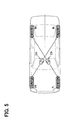
- the ground load of the rotating inner wheels is decreased, and the ground load of the rotating outer wheels is increased. Therefore, the behaviors of the right and left wheels are largely different between the rotating inner wheel and the rotating outer wheel. Accordingly, in the case of firming a model that couples the front wheels (driven wheels) and the rear wheels (driving wheels), as shown in Fig. 5 , it is preferable that the front right wheel (FR wheel) and the rear left wheel (RL wheel) are coupled by a virtual intermediate coupling element vibration model 23a, and the front left wheel (FL wheel) and the rear right wheel (RR wheel) are coupled by a virtual intermediate coupling element vibration model 23b.
- the respective systems that couple the front and rear wheels can also appropriately simulate the vibration state when the vehicle turns, and can prevent the correction quantity that impedes the travel stability and the turning property of the vehicle from being calculated. This is similarly applied to the chassis vibration model or the vehicle body vibration model which will be described later. Even when a model that the front wheel and the rear wheel at the right side are coupled with each other, and a model that the front wheel and the rear wheel at the left side are coupled with each other, it is possible to suppress the tire vibrations.
- the vibration generation mechanism in the longitudinal direction (rotating direction) of the tires will be described below.
- the rear wheels that are the driving wheels even if the wheels rotate due to the drive torque which is transmitted through the rear wheel shaft, because the tires receive the resistance by a frictional force of the road surface, the tires are twisted in the rotating direction and elastically deformed.
- the front wheels that are the driven wheels because the vehicle body is going to move in the longitudinal direction by the translational force generated by the rotations of the rear wheels, the front wheel tires are going to rotate by the frictional force of the road surface.
- the axle of the front wheels is going to keep the state by an inertia force, the tires are similarly twisted and elastically deformed.
- a restoring force are generated in the tires, and the tires are twisted back. The above phenomenon is repeated, thereby generating the vibrations in the longitudinal direction (rotating direction) of the tires.
- the amount of displacement x l corresponds to a difference between the amount of displacement x ltf of the front wheel rotating shaft and the amount of displacement x ltr of the rear wheel rotating shaft.
- x ⁇ 1 - K c / m f + K c / m r ⁇ x l - C c / m f + C c / m r ⁇ x ⁇ l - K gf / m f ⁇ x wf - C gr / m r ⁇ x ⁇ wr
- x ⁇ wf - K c / m f - r w 2 ⁇ K c / I w ⁇ x l - C c / m f - r w 2 ⁇ C c / I w ⁇ x ⁇ l - K gf / m f + r w 2 ⁇ K gf / I w + K gf / m tf ⁇ x wf - C gf / m f + r w 2 ⁇ C gf / I w + C gf / m tf ⁇ x ⁇ wf - 1 / m tf ⁇ F bf
- a relative displacement velocity dx wf /dt that is the first-order differential of the amount of relative displacement x wf in the vehicle body longitudinal direction between the front wheel rotating shaft and the front wheel tire road surface ground point can be applied as the internal state quantity that expresses the longitudinal vibrations of the front wheel tires.
- the relative displacement velocity is expressed by the following Expression 20 based on the state equation of Expression 19.
- a relative displacement velocity dx wr /dt that is the first-order differential of the amount of relative displacement x wr in the vehicle body longitudinal direction between the rear wheel rotating shaft and the rear wheel tire road surface ground point can be applied as the internal state quantity that expresses the longitudinal vibrations of the rear wheel tires.
- the relative displacement velocity is expressed by the following Expression 21 based on the state equation of Expression 19.
- a displacement velocity dx l /dt that is the first-order differential of the amount of displacement x l of the virtual intermediate coupling element can be applied as the internal state quantity that expresses the longitudinal vibrations of the virtual intermediate coupling element.
- the relative displacement velocity is expressed by the following Expression 22 based on the state equation of Expression 19.
- the front wheel tire longitudinal vibration estimate/control unit 43 in the tire control system 40 of Fig. 4 outputs the relative displacement velocity y 1 that is calculated according to the above Expression 20 as the internal state quantity to the controller with respect to the front right and left wheels as shown in Fig. 7 .
- the controller multiplies a given state feedback gain Ks by the relative displacement velocity y 1 to calculate the drive torque correction quantity. In this situation, the state feedback gain Ks is set so that the relative displacement velocity y 1 can rapidly approach zero.
- the drive torque correction quantity is input to the tire vibration model by feedback, and also output to a tire vibration correction drive torque calculation unit 44 as the drive torque correction quantity of the respective front right and left wheels.
- the rear wheel tire longitudinal vibration estimate/control unit 41 in the tire control system 40 outputs the relative displacement velocity y 2 that is calculated according to the above Expression 21 as the internal state quantity to the controller with respect to the rear right and left wheels as shown in Fig. 8 .
- the controller multiplies the given state feedback gain Ks by the relative displacement velocity y 2 to calculate the drive torque correction quantity.
- the drive torque correction quantity is input to the tire vibration model by feedback, and also output to the tire vibration correction drive torque calculation unit 44 as the drive torque correction quantity of the respective rear right and left wheels.
- the virtual intermediate coupling element longitudinal vibration estimate/control unit 42 in the tire control system 40 outputs the displacement velocity y 3 that is calculated according to the above Expression 22 as the internal state quantity to the controller with respect to a pair of FL wheel and RR wheel, and a pair of RF wheel and RL wheel as shown in Fig. 9 , respectively.
- the controller multiplies the given state feedback gain Ks by the relative displacement velocity y 3 to calculate the drive torque correction quantity.
- the respective state feedback gains Ks are set so that the relative displacement velocity y 3 can rapidly approach zero.
- the drive torque correction quantity is input to the virtual intermediate coupling element vibration model by feedback in each of the pairs, and the drive torque correction quantities are calculated with respect to the FL wheel and the RR wheel, and the FR wheel and the RL wheel, and then output to the tire vibration correction braking force calculation unit 44.
- the drive torque correction quantity that is calculated by the virtual intermediate coupling element longitudinal vibration estimate/control unit 42 inverts its sign and is then outputted to the tire vibration correction braking force calculation unit 44, as shown in Fig. 9 .
- the sign of the braking force correction quantity is inverted, the vibrations of the virtual intermediate coupling elements 80 and 90 are not suppressed, but conversely, the drive torque is connected so that the vibrations are excited.
- the virtual intermediate coupling elements are imaginary and merely virtual. Accordingly, even if the drive torque is so corrected as to vibrate the virtual intermediate coupling elements, the vibrations do not become actually larger. Rather, when the drive torque is so corrected as to vibrate the virtual intermediate coupling elements 80 and 90, thereby making it possible to shift the natural frequencies in the transmission system formed of the FL wheel and the RR wheel and the transmission system made up of the FR wheel and the RL wheel to the lower frequency side. As a result, it is confirmed that the vibrations in the transmission systems can be isolated.
- the sign of the internal state quantity (displacement velocity y 3 ) indicative of the vibration state of the virtual intermediate coupling element vibration model is inverted to calculate the drive torque correction quantity for vibration isolation.
- the present invention is not limited to this example.
- the signs of the drive torque correction quantities obtained from the internal state quantities indicative of the vibration state of the front wheel tires and the vibration state of the rear wheel tires are inverted to calculate the drive torque correction quantities that vibrate those vibration states, and the drive torque correction quantity obtained from the internal state quantity indicative of the vibration state of the virtual intermediate coupling element is calculated as the drive torque correction quantity which makes the vibration state approach zero without inverting its sign. Even with the combination of the above calculations, it is confirmed that the tire vibrations are suppressed as a whole.
- the drive torque correction quantities can be calculated so that all of the vibration states approach zero with respect to the vibration state of the front wheel tire, the vibration state of the rear wheel tire, and the vibration state of the virtual intermediate coupling element, or the drive torque correction quantities can be calculated so as to vibrate all of those vibration states as the occasion demands. That is, it is possible to arbitrarily combine a first manner (calculation of the correction quantity for vibration suppression) and a second manner (calculation of the correction quantity for vibration) which calculate the drive torque correction quantity with respect to the respective vibrations of the vibration state of the front wheel tires, the vibration state of the rear wheel tires, and the vibration state of the virtual intermediate coupling element.
- the tire vibration correction drive torque calculation unit 44 sums up (adds) the drive torque correction quantities that are calculated in the rear wheel tire longitudinal vibration estimate/control unit 41, the virtual intermediate coupling element longitudinal vibration estimate/control unit 42, and the front wheel tire longitudinal vibration estimate/control unit 43, respectively to calculate the final drive torque correction quantity in the tire control system 40.
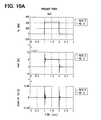
- Figs. 10A , 10B and 10C are the simulation results showing a difference in the longitudinal vibrations that are generated in the respective tires between a case of conducting a control (with control shown by a solid line) by the drive torque correction quantity that is calculated by the above tire control system 40 and a case of not conducting the control (without control shown by a dotted line), respectively.
- Fig. 10A shows a change in the drive torque T w , a change in the relative displacement amount X wf between the front wheel rotating shaft and the front wheel tire road surface ground point in the vehicle body longitudinal direction, and a change in the relative displacement velocity dx wf /dt.
- Fig. 10B shows a change in the drive torque T W , a change in the relative displacement amount x wr between the rear wheel rotating shaft and the rear wheel tire road surface ground point in the vehicle body longitudinal direction, and a change in the relative displacement velocity dx wr /dt.
- Fig. 10C shows a change in the drive torque T w , a change in the displacement amount x l of the virtual intermediate coupling element, and a change in the displacement velocity dx l /dt.
- the basic drive torque changes so as to rapidly rise up and fall down.
- the drive torque correction quantity in the case of no control
- a change in the respective displacement amounts and the respective displacement velocities are large to cause hunting.
- the drive torque correction quantity since the change in the drive torque T W is reduced to reduce the change in the displacement amount and the displacement velocity.
- the drive torque correction quantity is so calculated as to vibrate the virtual intermediate coupling element, the change in the displacement amounts x l and dx l /dt of the virtual intermediate coupling element becomes small and smooth.
- the basic drive torque is corrected by the drive torque correction quantity that is calculated by the tire vibration correction drive torque calculation unit 44, thereby making it possible to suppress the tire vibrations. Further, the tire vibrations are suppressed, thereby enabling such an advantage that the rigidity feeling of the tires is improved to be obtained.
- the chassis control system 50 includes a chassis longitudinal vibration estimate/control unit 51 having a chassis vibration model 24 that inputs the translational reaction force and a translational force which are received by the front wheel shaft and the rear wheel shaft, and expresses the motion state in the longitudinal direction of the chassis.
- the chassis longitudinal vibration estimate/control unit 51 calculates the drive torque correction quantity for suppressing the vibrations of the chassis in the longitudinal direction.
- the chassis has the longitudinal flexible rigidity of the suspension arm, and the rigidity of the frame and the bushing as the inner vibration element.
- the inner vibration elements (elastic elements) at the respective portions of the chassis is approximated by simple spring and damper elements as a whole, and those elements are disposed between the front wheel shaft, the rear wheel shaft and chassis frame.
- Fig. 11 shows a model diagram showing the chassis vibration model that is made up of the above concept.
- Basic equations that are bases for calculating the motion equations for expressing the longitudinal vibrations in the chassis vibration model are represented by Expression 23 to Expression 25.
- Expression 23 is an equation related to the chassis frame
- Expression 24 is an equation related to the front wheel shaft
- Expression 25 is an equation related to the rear wheel shaft.
- the state variables x 1 to x 4 and u 1 to u 2 are defined as the following Expression 28.
- x 1 x lf
- x 2 x ⁇ lf
- x 3 x lr
- x 4 x ⁇ lr
- u 1 F f
- u 2 F t
- a relative displacement velocity y that is the first-order differential of the relative displacement (x ltf - x ltr ) which is a difference between the amount of displacement x ltf of the front wheel shaft and the amount of displacement x ltr of the rear wheel shaft can be applied as the internal state quantity that expresses the longitudinal vibrations in the chassis vibration model.
- the relative displacement velocity y is expressed by the following Expression 34 based on the state equation of Expression 33.
- the chassis longitudinal vibration estimate/control unit 51 in the chassis control system 50 of Fig. 4 is divided into one system formed of FL wheel to RR wheel diagonal elements and another system formed of FR wheel to RL wheel diagonal elements, as shown in Fig. 12 .
- the relative displacement velocity y that is calculated by the above Expression 34 is output to the controller as the internal state quantity.
- the controller multiplies the given state feedback gain Ks by the relative displacement velocity y to calculate the rear wheel shaft target translational force for making the relative displacement velocity y rapidly approach zero in the respective systems.
- the rear wheel shaft target translational forces calculated with respect to the FL wheel to RR wheel diagonal element and the FR wheel to RL wheel diagonal element, respectively, are added together, and thereafter output to a drive shaft translational force/torque conversion unit 53 in a chassis vibration correction drive torque calculation unit 52.
- the rear wheel shaft translational force/torque conversion unit 53 converts the input rear wheel shaft target translational forces into the drive torque correction quantities. In the conversion, the rear wheel shaft translational force/torque conversion unit 53 calculates the drive torques that enable the forces corresponding to the respective input target translational forces to be exerted on the axle as the drive torque correction quantities.
- the frequency band (10 to 20 Hz) of the chassis vibrations and the frequency band (20 to 40 Hz) of the tire vibrations are different from each other. Accordingly, the drive torque correction quantity from the tire control system 40 and the drive torque correction quantity from the chassis control system 50 are also different in the frequency band from each other. For this reason, even if the respective drive torque correction quantities are added together, the respective correction components remain, thereby making it possible to suppress both of the chassis vibrations and the tire vibrations. Also, in the frequency band (1 to 2 Hz) of the vehicle body vibration which will be described later, the chassis vibrations and the tire vibrations are different from each other in the frequency band. For this reason, the drive torque correction quantities for suppressing the respective vibrations are calculated and added together, thereby making it possible to obtain the drive torque correction quantity that enable the vibrations of the respective portions of the vehicle to be suppressed.
- Fig. 13 is the simulation results showing a difference in the longitudinal vibrations that are generated in the chassis between a case of conducting a control (with control shown by a solid line) by the drive torque correction quantity that is calculated by the above chassis control system 50 and a case of not conducting the control (without control shown by a dotted line).
- Fig. 13 shows a change in the translational force F t that is propagated from the rear wheel tires to the rear wheel shaft, a change in the relative displacement (X ltf - x ltr ) that is a difference between the displacement amount x ltf of the front wheel shaft and the displacement amount X ltr of the rear wheel shaft, and a change in the relative displacement velocity (dx ltf /dt - dx ltr /dt).
- the drive torque is changed so that the translational force F t that is propagated to the rear wheel shaft rapidly rises up and falls down.
- the basic drive torque is corrected by the drive torque correction quantity that is calculated by the chassis vibration correction drive torque calculation unit 52, thereby making it possible to suppress the chassis longitudinal vibrations.
- the vehicle control system 60 includes a vehicle body pitch vibration and (/) vertical vibration estimate/control unit 61 having a vehicle body vibration model.
- the vehicle body vibration model expresses the pitching vibrations and the vertical vibrations (bouncing vibrations) of the vehicle body.
- the vehicle body pitch vibration/vertical vibration estimate/control unit 61 inputs the translational forces that are received from the front wheel shaft and the rear wheel shaft which are calculated in the chassis control system 50, and a drive torque reaction force that is applied directly to the vehicle body by the drive torque which is exerted on the rear wheel shaft which is the drive shaft to calculate the drive torque correction quantity for suppressing the pitching vibrations and the vertical vibrations.
- the vehicle body control system 60 includes a vehicle body rolling vibration and (/) engine rolling vibration estimate/control unit 62 having the vehicle body vibration model.
- the vehicle body vibration model expresses the rolling vibrations of the vehicle body and the rolling vibrations of the engine.
- the vehicle body rolling vibration/engine rolling vibration estimate/control unit 62 inputs the road surface reaction force that is exerted on the front wheels in the lateral direction and the drive torque reaction force to calculate the drive torque correction quantity for suppressing the vehicle body rolling vibrations and the engine rolling vibrations.
- the engine is mounted on the chassis frame through a mount.
- the engine is heavy in the weight and greatly affects the rolling vibrations of the vehicle body, and therefore modeled as a part of the vehicle body.
- the spring and damper elements in the vertical direction (up-down direction) due to the front wheel side and rear wheel side suspensions and the spring and damper elements in the vertical direction due to the elasticity of the front and rear wheel tires are considered.
- the spring and damper elements in the vertical direction of the suspension includes not only the coil spring and damper unit, but also the rigidity in the vertical direction as a whole, including the flexible rigidity of the suspension arm and the rigidity of the diverse bushings.
- Fig. 14 is an explanatory diagram for explaining the vehicle body vibration model formed to express the pitching vibrations and the bouncing vibrations.
- basic equations that are bases for calculating the motion equations for expressing the pitching vibrations and the bouncing vibrations are represented by Expression 35 to Expression 38.
- Expression 35 is an equation related to the vertical motion of the chassis frame
- Expression 36 is an equation related to the vertical motion of the front wheel rotation center
- Expression 37 is an equation related to the vertical motion of the rear wheel rotation center
- Expression 38 is an equation related to the pitching motion of the vehicle body.
- a sprung pitching velocity y 1 that is the first-order differential of the sprung pitch angle ⁇ p can be applied as the internal state quantity that expresses the pitching vibrations in the vehicle body vibration model.
- the sprung pitching velocity y 1 is expressed by the following Expression 53 based on the state equation of Expression 52.
- a vehicle vertical velocity y 2 that is the first-order differential of the amount of displacement x v of the vehicle body in the vertical direction can be applied as the internal state quantity that expresses the vertical vibrations (bouncing vibrations) in the vehicle body vibration model.
- the displacement velocity y 2 is expressed by the following Expression 54 based on the state equation of Expression 52.
- the vehicle body pitch vibration/vertical vibration estimate/control unit 61 in the vehicle body control system 60 of Fig. 4 includes a pitching vibration isolation control unit 65 and a bouncing vibration suppression control unit 66 as shown in Fig. 15 .
- the pitching vibration isolation control unit 65 and the bouncing vibration suppression control unit 66 calculate the drive torque correction quantities for suppressing the pitching vibrations and the bouncing vibrations, respectively.
- the vehicle body pitch vibration/vertical vibration estimate/control unit 61 adds those drive torque correction quantities to put those quantities together, and outputs one drive torque correction quantity.
- Fig. 16 is a block diagram showing the detailed functional structure of the pitching vibration isolation control unit 65.
- the sprung pitching vibration model of the FL wheel to RR wheel diagonal element and the sprung pitching vibration model of the FR wheel to RL wheel diagonal element are formed in the FL wheel to RR wheel diagonal pitching vibration isolation control unit and the FR wheel to RL wheel diagonal pitching vibration isolation control unit.
- the respective sprung pitching vibration models output the sprung pitching velocity y 1 that is calculated according to the above Expression 53 as the internal state quantity indicative of the pitching vibrations.
- the controller multiplies the sprung pitching velocity y 1 by the given state feedback gain Ks to calculate the torque correction quantity for suppressing the vibrations.
- Fig. 17 is a block diagram showing the detailed functional structure of the bouncing vibration isolation control unit 66 in Fig. 15 .
- the sprung bouncing vibration model of the FL wheel to RR wheel diagonal element and the sprung bouncing vibration model of the FR wheel to RL wheel diagonal element are formed in the FL wheel to RR wheel diagonal bouncing vibration suppression control unit and the FR wheel to RL wheel diagonal bouncing vibration suppression control unit.
- the respective sprung bouncing vibration models output the displacement velocity y 2 of the vehicle body in the vertical direction which is calculated according to the above Expression 54 as the internal state quantity indicative of the bouncing vibrations.
- the controller multiplies the displacement velocity y 2 of the vehicle body in the vertical direction by the given state feedback gain Ks to calculate the torque correction quantity for suppressing the bouncing vibrations.
- the drive torque correction quantities that are output by the FL wheel to RR wheel diagonal bouncing vibration suppression control unit and the FR wheel to RL wheel diagonal bouncing vibration suppression control unit, respectively, are added together to obtain the drive torque correction quantity for suppressing the bouncing vibrations.
- the sprung pitching velocity y 1 is applied as the internal state quantity indicative of the pitching vibrations
- the displacement velocity y 2 of the vehicle body in the vertical direction is applied as the internal state quantity indicative of the bouncing vibrations.
- the front wheel ground load and the rear wheel ground load change in opposite phase.
- the front wheel ground load and the rear wheel ground load change in the same phase.
- the front wheel ground load and the rear wheel ground load are parameters associated with the vibration state of the sprung (vehicle body).
- the front wheel load variation velocity indicative of a change in the front wheel ground load and the rear wheel load variation velocity indicative of a change in the rear wheel ground load can be applied as the internal state quantities indicative of the pitching vibrations and the bouncing vibrations.
- the front wheel load variation velocity is expressed by the following Expression 55
- the rear wheel load variation velocity is expressed by the following Expression 56.
- the front wheel load variation velocity and the rear wheel load variation velocity can be multiplied by the state feedback gain, respectively, thereby making it possible to calculate the drive torque correction quantity for suppressing the pitching vibrations and the bouncing vibrations.
- the variation velocity of the stability factor is indicated by the following Expression 57.
- the variation velocity of the stability factor is multiplied by a state feedback gain that is set so that the variation velocity approaches zero, thereby making it possible to calculate the drive torque correction quantity.
- y d S . F .
- Figs. 18A , 18B and 18C and Figs. 19A , 19B are the simulation results showing a difference in the pitching vibrations and the bouncing vibrations which are generated in the vehicle body between a case of conducting a control (with control shown by a solid line) by the vehicle body pitch vibrations of the above vehicle body control system 60 and the drive torque correction quantity that is calculated by the vertical vibration estimate control unit 61, and a case of not conducting the control (without control shown by a dotted line), respectively.
- Fig. 18A shows a change in the drive torque T w , a change in the vehicle body vertical displacement amount x v , and a change in the vehicle body vertical velocity dx v /dt.
- Fig. 18B shows a change in the drive torque T w , a change in the sprung pitch angle ⁇ P , and a change in the sprung pitching velocity d ⁇ p /dt.
- Fig. 18C shows a change in the drive torque T w , a change in the front wheel ground load wf, and a change in the varying velocity of the front wheel ground load dwf/dt.
- Fig. 18A shows a change in the drive torque T w , a change in the vehicle body vertical displacement amount x v , and a change in the vehicle body vertical velocity dx v /dt.
- Fig. 18B shows a change in the drive torque T w , a change in the sprung pitch angle ⁇ P
- FIG. 19A shows a change in the drive torque T w , a change in the rear wheel ground load wr, and a change in the varying velocity dwr/dt of the rear wheel ground load.
- Fig. 19B shows a change in the drive torque T w , a change in the stability factor sf, and a change in the varying velocity dsf/dt of the stability factor.
- the basic drive torque is corrected by the vehicle body pitch vibrations from the simulation results and the drive torque correction quantity that is calculated by the vertical vibration estimate control unit 61, thereby enabling the pitching vibrations and the bouncing vibrations of the vehicle body to be suppressed.
- the vehicle body vibration model inputs the lateral reaction force that is exerted on the front wheel shaft which is calculated by the front-wheel lateral road surface reaction force estimate unit 32 and a reaction force from the engine (and the transmission) which are mounted on the chassis frame through the engine mount to calculate the estimated rolling vibrations about the vehicle body rolling center and the rolling vibrations about the engine rolling center.
- the spring and damper elements in the vertical direction due to the front wheel side suspension and the rear wheel side suspension and the spring and damper elements of the engine mount are considered.
- Figs. 20A and 20B are diagrams for explaining a vehicle body vibration model formed for expressing the rolling vibration of the vehicle body and the rolling vibration of the engine.
- vehicle body vibration model basic equations that are bases for calculating the motion equations that express the rolling vibration of the vehicle body and the rolling vibration of the engine are represented by Expression 58 to Expression 59.
- Expression 58 is an equation related to the motion of the engine (and the transmission) in the rolling direction
- Expression 59 is an equation related to the motion of the vehicle body in the rolling direction.
- a vehicle rolling velocity y 1 that is the first-order differential of the rolling angle ⁇ r of the vehicle body can be applied as the internal state quantity that expresses the rolling vibrations of the vehicle body in the vehicle body vibration model.
- the vehicle body rolling velocity y 1 is expressed by the following Expression 68 based on the state equation of Expression 67.
- an engine rolling velocity y 2 that is the first-order differential of the engine rolling angle ⁇ e can be applied as the internal state quantity that expresses the engine rolling vibrations in the vehicle body vibration model.
- the engine rolling velocity y 2 is expressed by the following Expression 69 based on the state equation of Expression 67.
- the vehicle body rolling vibration/engine rolling vibration estimate/control unit 62 in the vehicle body control system 60 of Fig. 4 includes a vehicle body rolling vibration control unit 62a for suppressing the rolling vibrations of the vehicle body, and an engine rolling vibration control unit 62b for suppressing the rolling vibrations of the engine.
- Fig. 21 is a block diagram showing the detailed functional structure of the vehicle body roll vibration control unit 62a.
- the vehicle body roll vibration control unit 62a is made up of the FL wheel to RR wheel diagonal vehicle body rolling vibration control unit and the FR wheel to RL wheel diagonal vehicle body rolling vibration control unit.
- the vehicle body rolling vibration model of the FL wheel to RR wheel diagonal element and the vehicle body rolling vibration model of the FR wheel to RL wheel diagonal element are formed in the FL wheel to RR wheel diagonal vehicle body rolling vibration control unit and the FR wheel to RL wheel diagonal vehicle body rolling vibration control unit.
- the respective vehicle body rolling vibration models output the vehicle body rolling angular velocity y 1 that is calculated according to the above Expression 68 as the internal state quantity indicative of the vehicle body rolling vibrations.
- the respective controllers multiply the vehicle body rolling angular velocity y 1 by the given state feedback gain Ks to calculate the torque correction quantity.
- the drive torque correction quantities that are output by the FL wheel to RR wheel diagonal vehicle body rolling vibration control unit and the FR wheel to RL wheel diagonal vehicle body rolling vibration control unit, respectively, are added together to obtain the drive torque correction quantity for suppressing the vehicle body rolling vibrations.
- Fig. 22 is a block diagram showing the detailed functional structure of the engine roll vibration control unit 62b.
- the engine roll vibration control unit has an engine rolling vibration model, and the engine rolling vibration model outputs the engine rolling angular velocity y 2 that is calculated according to the above Expression 69 as the internal state quantity indicative of the engine rolling vibrations.
- the controller multiplies the given state feedback gain Ks by the engine rolling angular velocity y 2 to calculate the torque correction quantity.
- Figs. 23A and 23B are the simulation results showing a difference in the rolling vibrations which are generated in the vehicle body and the engine between a case of conducting a control (with control shown by a solid line) by the vehicle body rolling vibrations of the above vehicle body control system 60 and the drive torque correction quantity that is calculated by the engine rolling vibration estimate/control unit 62, and a case of not conducting the control (without control shown in a dotted line), respectively.
- Fig. 23A shows a change in the drive torque T W , a change in the rolling angle ⁇ e of the engine, and a change in the engine rolling velocity d ⁇ e /dt.
- Fig. 23B shows a change in the drive torque T w , a change in the rolling angle of the vehicle body, and a change in the vehicle body rolling velocity d ⁇ r /dt.
- the basic drive torque changes so as to rapidly rise up and fall down.
- the vehicle vibration model that is separated and hierarchized into the tire vibration model, the chassis vibration model, and the vehicle body vibration model is formed in the manner described above. For this reason, it is possible to express the respective models as the reduced-order linear models, and the capacity for storing the vehicle vibration model can be reduced, and the calculation load based on the vehicle vibration model can be reduced in the engine/drive system ECU 10.
- the virtual intermediate coupling element vibration model that is imaginary is set between the front wheel tire vibration model and the rear wheel tire vibration model.
- the influence of the vibrating state which is exerted between the front wheel tire and the rear wheel tire can be considered while the tire vibration model and the chassis vibration model are separated from each other.
- the engine/drive system ECU 10 appropriately corrects the drive torque that is given to the driving wheels of the vehicle to suppress the vibrations which are generated in the respective portions of the vehicle.
- the vibration suppression control for suppressing the vibrations at the respective portions of the vehicle can be conducted by an ECU that controls the device.
- the brake system ECU 20 that controls the brake actuator which adjusts the braking forces (brake pressures) of the respective wheels appropriately corrects the braking forces of the respective wheels of the vehicle, thereby making it possible to suppress the vibrations at the respective portions of the vehicle. Since the travel resistance changes with a change in the braking force of the wheels, it is possible to change the motion states of the wheels and other portions in the vehicle.
- a vehicle having an electric motor in addition to an internal combustion engine as the drive source of the vehicle as in a hybrid vehicle that drives the common driving wheels by the internal combustion engine and the electric motor, and an electric type four-wheel drive vehicle that drives one of front wheels and rear wheels by the internal combustion engine, and drives the other wheels by an electric motor as the occasion demands.
- the electric motor can suppress the vibrations at the respective portions under the control.
- the vibration suppression control can be conducted by plural actuators.
- the engine/drive system ECU 10 corrects the drive torque to suppress the vibrations of the vehicle body
- the brake system ECU 20 and/or an ECU that controls the above electric motor suppresses the vibrations of the chassis or the tires under the control.
- the same chassis vibration model and tire vibration model as those described in the above embodiment can be used. Then, the drive torque (correction quantity) for reducing the vibrations and the braking force correction quantity can be calculated based on the internal state quantities indicative of the respective vibration states, which are output from the chassis vibration model and the tire vibration model.
- the vehicle control system is applied to the FR vehicle that steers the front wheels and drives the rear wheels.
- the vehicle to be applied can be an FF vehicle or a 4WD vehicle.
Landscapes
- Engineering & Computer Science (AREA)
- Mechanical Engineering (AREA)
- Transportation (AREA)
- Chemical & Material Sciences (AREA)
- Combustion & Propulsion (AREA)
- Automation & Control Theory (AREA)
- General Engineering & Computer Science (AREA)
- Acoustics & Sound (AREA)
- Aviation & Aerospace Engineering (AREA)
- Physics & Mathematics (AREA)
- Computer Hardware Design (AREA)
- Control Of Driving Devices And Active Controlling Of Vehicle (AREA)
- Regulating Braking Force (AREA)
- Electric Propulsion And Braking For Vehicles (AREA)
Applications Claiming Priority (1)
| Application Number | Priority Date | Filing Date | Title |
|---|---|---|---|
| JP2007097792A JP4333767B2 (ja) | 2007-04-03 | 2007-04-03 | 車両制御装置 |
Publications (3)
| Publication Number | Publication Date |
|---|---|
| EP1978279A2 true EP1978279A2 (de) | 2008-10-08 |
| EP1978279A3 EP1978279A3 (de) | 2009-08-19 |
| EP1978279B1 EP1978279B1 (de) | 2010-08-18 |
Family
ID=39627659
Family Applications (1)
| Application Number | Title | Priority Date | Filing Date |
|---|---|---|---|
| EP08006687A Expired - Fee Related EP1978279B1 (de) | 2007-04-03 | 2008-04-01 | Fahrzeugsteuerungssystem |
Country Status (5)
| Country | Link |
|---|---|
| US (1) | US7970516B2 (de) |
| EP (1) | EP1978279B1 (de) |
| JP (1) | JP4333767B2 (de) |
| CN (1) | CN101279578B (de) |
| DE (1) | DE602008002171D1 (de) |
Cited By (5)
| Publication number | Priority date | Publication date | Assignee | Title |
|---|---|---|---|---|
| US7970516B2 (en) * | 2007-04-03 | 2011-06-28 | Denso Corporation | Vehicle control system |
| CN102197207B (zh) * | 2009-10-05 | 2014-04-09 | 丰田自动车株式会社 | 车辆减振控制装置 |
| EP2816211A4 (de) * | 2012-02-16 | 2016-12-28 | Nissan Motor | Vorrichtung zur steuerung der dämpfung von fahrzeugkarosserieschwingungen |
| CN113867149A (zh) * | 2021-10-09 | 2021-12-31 | 清华大学 | 制动末期的车辆纵向平顺性优化方法、系统、介质及设备 |
| CN115235663A (zh) * | 2022-07-07 | 2022-10-25 | 东风柳州汽车有限公司 | 一种轮胎夹持装置 |
Families Citing this family (26)
| Publication number | Priority date | Publication date | Assignee | Title |
|---|---|---|---|---|
| US8140238B2 (en) * | 2007-10-26 | 2012-03-20 | Ford Global Technologies, Llc | Detection and control of power induced hop during traction control in a vehicle |
| US7853389B2 (en) * | 2007-10-29 | 2010-12-14 | Ford Global Technologies, Llc | Traction control for performance and demonstration spin |
| US8244445B2 (en) * | 2007-10-30 | 2012-08-14 | Ford Global Technologies, Llc | Stuck vehicle with time and pedal related traction control |
| CN102159819A (zh) * | 2008-10-31 | 2011-08-17 | 丰田自动车株式会社 | 车辆的减振控制装置 |
| JP5171594B2 (ja) | 2008-12-15 | 2013-03-27 | 日立建機株式会社 | 電動車両及びそのピッチング制御装置 |
| WO2010082303A1 (ja) * | 2009-01-13 | 2010-07-22 | トヨタ自動車株式会社 | 車両制御装置 |
| DE112010001470B4 (de) * | 2009-03-30 | 2018-05-24 | Honda Motor Co., Ltd. | Aktive - Schwingungsdämpfung -Lagereinrichtung |
| AT10812U3 (de) * | 2009-06-16 | 2010-03-15 | Avl List Gmbh | Prüfstandsanordnung |
| JP5273011B2 (ja) * | 2009-10-22 | 2013-08-28 | トヨタ自動車株式会社 | 振動抑制装置、振動抑制方法、およびプログラム |
| JP5606043B2 (ja) * | 2009-11-09 | 2014-10-15 | 東洋電機製造株式会社 | 電気車駆動システム |
| US8200404B2 (en) * | 2010-01-13 | 2012-06-12 | Ford Global Technologies, Llc | Controlling wheel hop in a vehicle driveline |
| JP5540894B2 (ja) * | 2010-05-31 | 2014-07-02 | 日産自動車株式会社 | 車両の制振制御装置 |
| CN102639351B (zh) * | 2010-06-07 | 2015-11-25 | 丰田自动车株式会社 | 混合动力车辆及其控制方法 |
| JP5533405B2 (ja) * | 2010-08-03 | 2014-06-25 | トヨタ自動車株式会社 | 車両の制駆動力制御装置 |
| JP5634893B2 (ja) * | 2011-01-21 | 2014-12-03 | 本田技研工業株式会社 | 能動型振動騒音制御装置 |
| CN102521430A (zh) * | 2011-11-20 | 2012-06-27 | 安徽安凯汽车股份有限公司 | 一种电动汽车的联合仿真方法 |
| KR101416355B1 (ko) * | 2011-12-09 | 2014-07-09 | 현대자동차 주식회사 | 엔진 토크 제어 방법 |
| JP5487252B2 (ja) * | 2012-07-09 | 2014-05-07 | 日立建機株式会社 | 電動車両及びそのピッチング制御装置 |
| JP2014193667A (ja) * | 2013-03-28 | 2014-10-09 | Jtekt Corp | 車両用操舵装置 |
| CN104343884A (zh) * | 2013-07-23 | 2015-02-11 | 上海三一重机有限公司 | 一种矿车油气悬架阻尼控制方法 |
| JP6206258B2 (ja) * | 2014-03-06 | 2017-10-04 | 富士通株式会社 | 軌跡推定装置、軌跡推定方法およびプログラム |
| JP6394300B2 (ja) * | 2014-11-10 | 2018-09-26 | 株式会社デンソー | レーンキープ制御システム |
| JP6245217B2 (ja) * | 2015-05-19 | 2017-12-13 | トヨタ自動車株式会社 | 車両の状態量推定装置 |
| CN105865731B (zh) * | 2016-03-30 | 2018-11-30 | 北京林业大学 | 一种电动汽车共振转速的实时检测系统及其控制方法 |
| CN108058561B (zh) * | 2017-12-19 | 2023-07-04 | 东风汽车集团有限公司 | 一种可改变悬挂系统的刚度及阻尼特性的主动式悬架系统 |
| JP7223850B2 (ja) * | 2019-07-02 | 2023-02-16 | 日産自動車株式会社 | 車両に搭載されるエンジンの駆動制御方法、及び、車両に搭載されるエンジンの駆動制御装置 |
Citations (1)
| Publication number | Priority date | Publication date | Assignee | Title |
|---|---|---|---|---|
| DE10353692A1 (de) | 2002-11-19 | 2004-06-03 | Denso Corp., Kariya | Vibrationssteuervorrichtung für Kraftfahrzeuge |
Family Cites Families (43)
| Publication number | Priority date | Publication date | Assignee | Title |
|---|---|---|---|---|
| US4770438A (en) * | 1984-01-20 | 1988-09-13 | Nissan Motor Co., Ltd. | Automotive suspension control system with road-condition-dependent damping characteristics |
| JP2681772B2 (ja) * | 1985-11-07 | 1997-11-26 | 株式会社豊田中央研究所 | 振動制御装置 |
| JPH0799488B2 (ja) * | 1986-10-31 | 1995-10-25 | 株式会社豊田中央研究所 | 振動制御装置 |
| JPH02142942A (ja) * | 1988-11-25 | 1990-06-01 | Atsugi Unisia Corp | 液圧緩衝器 |
| DE69000232T2 (de) * | 1989-05-09 | 1992-12-24 | Nippon Denso Co | Radaufhaengungsregelsystem. |
| US5383124A (en) * | 1989-05-20 | 1995-01-17 | Robert Bosch Gmbh | Process for undercarriage regulation |
| DE68915442T2 (de) * | 1989-08-03 | 1995-01-05 | Nippon Denso Co | Kontrollsystem für die Dämpfkraft von Stossdämpfern. |
| DE69031794T2 (de) * | 1989-09-11 | 1998-04-23 | Toyota Motor Co Ltd | Aufhängungssteuersystem |
| EP0417702B1 (de) * | 1989-09-11 | 1997-01-08 | Toyota Jidosha Kabushiki Kaisha | Aufhängungsregelsystem |
| ES2041145T3 (es) | 1989-11-02 | 1993-11-01 | General Motors Corporation | Aparato de suspension de vehiculos. |
| US5062657A (en) | 1989-11-02 | 1991-11-05 | General Motors Corporation | On/off semi-active suspension control |
| US5097419A (en) * | 1990-06-08 | 1992-03-17 | Monroe Auto Equipment Company | Method and apparatus for dynamic leveling |
| US5322319A (en) * | 1990-09-17 | 1994-06-21 | Mitsubishi Jidosha Kogyo Kabushiki Kaisha | Active suspension apparatus for a vehicle |
| JPH04201614A (ja) * | 1990-11-30 | 1992-07-22 | Nissan Motor Co Ltd | 能動型サスペンション |
| KR950007524B1 (ko) * | 1991-02-06 | 1995-07-11 | 혼다기겡 고오교오 가부시기가이샤 | 가진장치 및 그 제어방법 |
| US5430646A (en) * | 1991-02-22 | 1995-07-04 | Atsugi Unisia Corporation | System and method for controlling damping force coefficient of shock absorber applicable to automotive supension |
| JPH0699718A (ja) * | 1992-09-18 | 1994-04-12 | Nippondenso Co Ltd | 減衰力可変ショックアブソーバ制御装置 |
| JP3131049B2 (ja) * | 1992-09-30 | 2001-01-31 | マツダ株式会社 | 車両のサスペンション装置 |
| JPH07267131A (ja) | 1994-03-31 | 1995-10-17 | Mazda Motor Corp | シャーシフレームを備えた車体の振動低減構造 |
| US6293530B1 (en) * | 1995-01-10 | 2001-09-25 | Liquidspring Technologies, Inc. | Compressible liquid vibration control system |
| JP3125603B2 (ja) * | 1994-10-07 | 2001-01-22 | トヨタ自動車株式会社 | サスペンション制御装置 |
| US5570288A (en) * | 1995-03-27 | 1996-10-29 | General Motors Corporation | Vehicle suspension control using a scaled wheel demand force |
| US5606503A (en) * | 1995-03-27 | 1997-02-25 | General Motors Corporation | Suspension system control responsive to ambient temperature |
| US5570289A (en) * | 1995-03-27 | 1996-10-29 | General Motors Corporation | Vehicle suspension control with wheel and body demand force phase determination |
| JP3133233B2 (ja) * | 1995-07-06 | 2001-02-05 | 株式会社ユニシアジェックス | ステップモータの駆動制御方法 |
| CN1199701C (zh) * | 1997-11-07 | 2005-05-04 | 世嘉股份有限公司 | 游戏装置 |
| JP3644218B2 (ja) | 1997-11-11 | 2005-04-27 | 株式会社豊田中央研究所 | アンチロックブレーキ制御装置 |
| US6000703A (en) * | 1997-11-12 | 1999-12-14 | Case Corporation | Active suspension system for a work vehicle having adjustable performance parameters |
| US5983168A (en) * | 1998-03-23 | 1999-11-09 | Marquip, Inc. | Phase shift accommodation in active vibration damping system |
| WO2001000468A1 (en) * | 1999-06-30 | 2001-01-04 | Kelsey-Hayes Company | Integrated braking and suspension control systems for a vehicle |
| US6898501B2 (en) * | 1999-07-15 | 2005-05-24 | Cnh America Llc | Apparatus for facilitating reduction of vibration in a work vehicle having an active CAB suspension system |
| GB2356685B (en) * | 1999-11-27 | 2003-01-29 | Rover Group | Vehicle braking control systems |
| JP4868689B2 (ja) * | 2000-06-23 | 2012-02-01 | 株式会社ブリヂストン | 路面状態推定方法、及び、路面状態推定装置 |
| CN1137826C (zh) * | 2000-11-18 | 2004-02-11 | 肖东平 | 主动式汽车智能电子避震方法及系统 |
| US6389341B1 (en) * | 2001-01-12 | 2002-05-14 | Davis Family Irrevocable Trust | Control system for a vehicle suspension |
| JP2002337520A (ja) | 2001-05-17 | 2002-11-27 | Toyota Motor Corp | タイヤ異常判定装置 |
| US6598885B2 (en) * | 2001-10-23 | 2003-07-29 | Liquidspring Technologies, Inc. | Single valve control of damping and stiffness in a liquid spring system |
| US6679504B2 (en) * | 2001-10-23 | 2004-01-20 | Liquidspring Technologies, Inc. | Seamless control of spring stiffness in a liquid spring system |
| DE10158026B4 (de) * | 2001-11-27 | 2005-11-24 | Lucas Automotive Gmbh | Verfahren zum Betreiben eines Antiblockiersystems |
| JP4161923B2 (ja) * | 2004-03-09 | 2008-10-08 | 株式会社デンソー | 車両安定化制御システム |
| JP4554426B2 (ja) | 2005-04-25 | 2010-09-29 | 独立行政法人科学技術振興機構 | シミュレーションモデル作成方法及びプログラム並びにプログラムを記録した記録媒体 |
| CN100418799C (zh) * | 2005-10-14 | 2008-09-17 | 上海燃料电池汽车动力系统有限公司 | 车速路面感应型汽车半主动悬架天棚阻尼控制算法 |
| JP4333767B2 (ja) * | 2007-04-03 | 2009-09-16 | 株式会社デンソー | 車両制御装置 |
-
2007
- 2007-04-03 JP JP2007097792A patent/JP4333767B2/ja not_active Expired - Fee Related
-
2008
- 2008-04-01 EP EP08006687A patent/EP1978279B1/de not_active Expired - Fee Related
- 2008-04-01 DE DE602008002171T patent/DE602008002171D1/de active Active
- 2008-04-02 US US12/080,437 patent/US7970516B2/en active Active
- 2008-04-02 CN CN2008100895270A patent/CN101279578B/zh not_active Expired - Fee Related
Patent Citations (1)
| Publication number | Priority date | Publication date | Assignee | Title |
|---|---|---|---|---|
| DE10353692A1 (de) | 2002-11-19 | 2004-06-03 | Denso Corp., Kariya | Vibrationssteuervorrichtung für Kraftfahrzeuge |
Cited By (7)
| Publication number | Priority date | Publication date | Assignee | Title |
|---|---|---|---|---|
| US7970516B2 (en) * | 2007-04-03 | 2011-06-28 | Denso Corporation | Vehicle control system |
| CN102197207B (zh) * | 2009-10-05 | 2014-04-09 | 丰田自动车株式会社 | 车辆减振控制装置 |
| US8825291B2 (en) | 2009-10-05 | 2014-09-02 | Toyota Jidosha Kabushiki Kaisha | Vehicle vibration-damping controlling apparatus |
| EP2816211A4 (de) * | 2012-02-16 | 2016-12-28 | Nissan Motor | Vorrichtung zur steuerung der dämpfung von fahrzeugkarosserieschwingungen |
| CN113867149A (zh) * | 2021-10-09 | 2021-12-31 | 清华大学 | 制动末期的车辆纵向平顺性优化方法、系统、介质及设备 |
| CN115235663A (zh) * | 2022-07-07 | 2022-10-25 | 东风柳州汽车有限公司 | 一种轮胎夹持装置 |
| CN115235663B (zh) * | 2022-07-07 | 2024-04-05 | 东风柳州汽车有限公司 | 一种轮胎夹持装置 |
Also Published As
| Publication number | Publication date |
|---|---|
| EP1978279B1 (de) | 2010-08-18 |
| DE602008002171D1 (de) | 2010-09-30 |
| JP2008254538A (ja) | 2008-10-23 |
| JP4333767B2 (ja) | 2009-09-16 |
| CN101279578B (zh) | 2010-06-09 |
| CN101279578A (zh) | 2008-10-08 |
| US20080249689A1 (en) | 2008-10-09 |
| US7970516B2 (en) | 2011-06-28 |
| EP1978279A3 (de) | 2009-08-19 |
Similar Documents
| Publication | Publication Date | Title |
|---|---|---|
| EP1978279B1 (de) | Fahrzeugsteuerungssystem | |
| EP1978278B1 (de) | Fahrzeugsteuerungssystem | |
| CN101528525B (zh) | 车辆的减振控制装置 | |
| CN102582388B (zh) | 车辆的减振控制装置 | |
| US8165750B2 (en) | Vehicle motion control device and method | |
| EP1632382B1 (de) | Stabilisierungssystem für Kraftfahrzeuge mit Ausgleich von Schwankungen des Fahrwiderstands | |
| US8489300B2 (en) | Vibration control apparatus for automotive vehicle | |
| CN102958717B (zh) | 车辆减振控制装置 | |
| US9950703B2 (en) | Vehicle with independently driven multiple axes, and controller which independently drives multiple axles | |
| US10023192B2 (en) | Vibration control device and vibration control system | |
| US20110137514A1 (en) | Driving force controlling apparatus and control method of driving force controlling apparatus | |
| EP2615006A1 (de) | Vorrichtung zur steuerung der dämpfung von fahrzeugkarosserieschwingungen | |
| US8892303B2 (en) | Vehicle control device | |
| JP6252456B2 (ja) | 車両制御装置 | |
| Laneve | Traction Control System development for an AWD hybrid vehicle | |
| JPH0885471A (ja) | 車両運動制御装置 | |
| KR20070016160A (ko) | 동적 차축 하중 전달을 상쇄시키기 위한 방법 | |
| Margolis et al. | A Bond Graph Model Incorporating Sensors, Actuators and Vehicle Dynamics for Developing Controllers for Vehicle Safety | |
| Liu et al. | Co-simulation of driveline torque bias controls |
Legal Events
| Date | Code | Title | Description |
|---|---|---|---|
| PUAI | Public reference made under article 153(3) epc to a published international application that has entered the european phase |
Free format text: ORIGINAL CODE: 0009012 |
|
| AK | Designated contracting states |
Kind code of ref document: A2 Designated state(s): AT BE BG CH CY CZ DE DK EE ES FI FR GB GR HR HU IE IS IT LI LT LU LV MC MT NL NO PL PT RO SE SI SK TR |
|
| AX | Request for extension of the european patent |
Extension state: AL BA MK RS |
|
| PUAL | Search report despatched |
Free format text: ORIGINAL CODE: 0009013 |
|
| AK | Designated contracting states |
Kind code of ref document: A3 Designated state(s): AT BE BG CH CY CZ DE DK EE ES FI FR GB GR HR HU IE IS IT LI LT LU LV MC MT NL NO PL PT RO SE SI SK TR |
|
| AX | Request for extension of the european patent |
Extension state: AL BA MK RS |
|
| GRAP | Despatch of communication of intention to grant a patent |
Free format text: ORIGINAL CODE: EPIDOSNIGR1 |
|
| 17P | Request for examination filed |
Effective date: 20091111 |
|
| AKX | Designation fees paid |
Designated state(s): DE FR |
|
| GRAS | Grant fee paid |
Free format text: ORIGINAL CODE: EPIDOSNIGR3 |
|
| GRAA | (expected) grant |
Free format text: ORIGINAL CODE: 0009210 |
|
| AK | Designated contracting states |
Kind code of ref document: B1 Designated state(s): DE FR |
|
| REF | Corresponds to: |
Ref document number: 602008002171 Country of ref document: DE Date of ref document: 20100930 Kind code of ref document: P |
|
| PLBE | No opposition filed within time limit |
Free format text: ORIGINAL CODE: 0009261 |
|
| STAA | Information on the status of an ep patent application or granted ep patent |
Free format text: STATUS: NO OPPOSITION FILED WITHIN TIME LIMIT |
|
| 26N | No opposition filed |
Effective date: 20110519 |
|
| REG | Reference to a national code |
Ref country code: DE Ref legal event code: R097 Ref document number: 602008002171 Country of ref document: DE Effective date: 20110519 |
|
| REG | Reference to a national code |
Ref country code: FR Ref legal event code: PLFP Year of fee payment: 8 |
|
| REG | Reference to a national code |
Ref country code: FR Ref legal event code: PLFP Year of fee payment: 9 |
|
| REG | Reference to a national code |
Ref country code: FR Ref legal event code: PLFP Year of fee payment: 10 |
|
| PGFP | Annual fee paid to national office [announced via postgrant information from national office to epo] |
Ref country code: DE Payment date: 20170419 Year of fee payment: 10 Ref country code: FR Payment date: 20170419 Year of fee payment: 10 |
|
| REG | Reference to a national code |
Ref country code: DE Ref legal event code: R119 Ref document number: 602008002171 Country of ref document: DE |
|
| PG25 | Lapsed in a contracting state [announced via postgrant information from national office to epo] |
Ref country code: DE Free format text: LAPSE BECAUSE OF NON-PAYMENT OF DUE FEES Effective date: 20181101 |
|
| PG25 | Lapsed in a contracting state [announced via postgrant information from national office to epo] |
Ref country code: FR Free format text: LAPSE BECAUSE OF NON-PAYMENT OF DUE FEES Effective date: 20180430 |