EP1977940B1 - Verfahren zur Erkennung eines Aquaplaning-Phänomens eines Reifens auf einer Fahrbahn - Google Patents
Verfahren zur Erkennung eines Aquaplaning-Phänomens eines Reifens auf einer Fahrbahn Download PDFInfo
- Publication number
- EP1977940B1 EP1977940B1 EP08154063.5A EP08154063A EP1977940B1 EP 1977940 B1 EP1977940 B1 EP 1977940B1 EP 08154063 A EP08154063 A EP 08154063A EP 1977940 B1 EP1977940 B1 EP 1977940B1
- Authority
- EP
- European Patent Office
- Prior art keywords
- tyre
- signal
- ground
- instantaneous value
- tread
- Prior art date
- Legal status (The legal status is an assumption and is not a legal conclusion. Google has not performed a legal analysis and makes no representation as to the accuracy of the status listed.)
- Not-in-force
Links
- 238000000034 method Methods 0.000 title claims description 16
- 238000005259 measurement Methods 0.000 claims description 41
- 230000006835 compression Effects 0.000 claims description 18
- 238000007906 compression Methods 0.000 claims description 18
- 230000001960 triggered effect Effects 0.000 claims description 16
- 238000012545 processing Methods 0.000 claims description 13
- 238000005096 rolling process Methods 0.000 claims description 11
- 230000035882 stress Effects 0.000 description 37
- XLYOFNOQVPJJNP-UHFFFAOYSA-N water Substances O XLYOFNOQVPJJNP-UHFFFAOYSA-N 0.000 description 30
- 230000006870 function Effects 0.000 description 7
- 239000007788 liquid Substances 0.000 description 5
- 230000005540 biological transmission Effects 0.000 description 4
- 235000008429 bread Nutrition 0.000 description 4
- 238000001514 detection method Methods 0.000 description 4
- 230000000694 effects Effects 0.000 description 4
- 238000006073 displacement reaction Methods 0.000 description 3
- 238000005516 engineering process Methods 0.000 description 2
- 230000005355 Hall effect Effects 0.000 description 1
- 230000001133 acceleration Effects 0.000 description 1
- 230000003466 anti-cipated effect Effects 0.000 description 1
- 230000008901 benefit Effects 0.000 description 1
- 239000003990 capacitor Substances 0.000 description 1
- 230000008859 change Effects 0.000 description 1
- 239000003086 colorant Substances 0.000 description 1
- 230000000295 complement effect Effects 0.000 description 1
- 239000006185 dispersion Substances 0.000 description 1
- 230000009429 distress Effects 0.000 description 1
- 230000005684 electric field Effects 0.000 description 1
- 238000000605 extraction Methods 0.000 description 1
- 230000002706 hydrostatic effect Effects 0.000 description 1
- 238000012986 modification Methods 0.000 description 1
- 230000004048 modification Effects 0.000 description 1
- 230000008569 process Effects 0.000 description 1
- 230000000750 progressive effect Effects 0.000 description 1
- 230000003014 reinforcing effect Effects 0.000 description 1
- 238000005070 sampling Methods 0.000 description 1
- 238000012546 transfer Methods 0.000 description 1
Images


Classifications
-
- B—PERFORMING OPERATIONS; TRANSPORTING
- B60—VEHICLES IN GENERAL
- B60T—VEHICLE BRAKE CONTROL SYSTEMS OR PARTS THEREOF; BRAKE CONTROL SYSTEMS OR PARTS THEREOF, IN GENERAL; ARRANGEMENT OF BRAKING ELEMENTS ON VEHICLES IN GENERAL; PORTABLE DEVICES FOR PREVENTING UNWANTED MOVEMENT OF VEHICLES; VEHICLE MODIFICATIONS TO FACILITATE COOLING OF BRAKES
- B60T8/00—Arrangements for adjusting wheel-braking force to meet varying vehicular or ground-surface conditions, e.g. limiting or varying distribution of braking force
- B60T8/17—Using electrical or electronic regulation means to control braking
- B60T8/172—Determining control parameters used in the regulation, e.g. by calculations involving measured or detected parameters
- B60T8/1725—Using tyre sensors, e.g. Sidewall Torsion sensors [SWT]
-
- B—PERFORMING OPERATIONS; TRANSPORTING
- B60—VEHICLES IN GENERAL
- B60T—VEHICLE BRAKE CONTROL SYSTEMS OR PARTS THEREOF; BRAKE CONTROL SYSTEMS OR PARTS THEREOF, IN GENERAL; ARRANGEMENT OF BRAKING ELEMENTS ON VEHICLES IN GENERAL; PORTABLE DEVICES FOR PREVENTING UNWANTED MOVEMENT OF VEHICLES; VEHICLE MODIFICATIONS TO FACILITATE COOLING OF BRAKES
- B60T2210/00—Detection or estimation of road or environment conditions; Detection or estimation of road shapes
- B60T2210/10—Detection or estimation of road conditions
- B60T2210/13—Aquaplaning, hydroplaning
Definitions
- the present invention relates to the detection of a beginning of hydroplaning phenomenon of a tire on a wet pavement traveled by a vehicle. It relates more particularly to this detection from the measurement of stresses in the tread of a tire of said vehicle.
- the hydroplaning phenomenon is characterized by the momentary presence of a quantity of water between the ground comprising the roadway and the part of the tread of the tire in contact with the ground.
- the film formed by the presence of water prevents all or part of this contact: there is more adhesion and therefore more transfer of effort between the vehicle and the roadway.
- a film of water between all or part of the tread of the tire in contact with the ground and the roadway is formed, when the flow of water flowing between these two surfaces becomes greater than the flow of water that can evacuate at once the pattern of the floor covering and that of the tire.
- This saturation effect is a function of the height of water on the road and the speed of the vehicle.
- hydroplaning during an acceleration by a motor force, during a deceleration by a braking effort or during a change of direction are important and may involve a partial or total loss of control of the vehicle. It is therefore essential when driving on a wet ground to be able to anticipate the conditions for hydroplaning.
- the object of the invention is to detect a start of the hydroplaning phenomenon from different measurements.
- the invention relates to a method for detecting a hydroplaning state of a tire of a vehicle operating on a wet floor according to claim 1.
- the position of a measuring point corresponds to a longitudinal measurement in which the measurement of the compression stress ⁇ z is performed , according to a linear deployment of the portion of the tread corresponding to the portion of the signal extracted and d ⁇ z d x represents the first derivative of the measurement of stress according to the value x of the position of the sensor on the longitudinal axis X of rolling of the tire in the plane of the roadway.
- an alarm is triggered when the instantaneous value ⁇ E exceeds a given threshold.
- R z ⁇ zi - ⁇ zd ⁇ zd and C is equal to -1.
- an alarm is triggered when the momentary value R z is greater than a given value, and preferably when the momentary value is positive.
- R z ⁇ zi ⁇ zd and C is 0; in this case, an alert is triggered preferentially when the ratio becomes greater than or equal to 1.
- the preferential threshold corresponds to the situation where the two trays are of substantially identical amplitude.
- the evolution of this criterion is progressive as a function of the driving speed.
- the first criteria is related to a jump of the value of ⁇ E which occurs when the front separating the two plates becomes less marked than that of the first plate. This threshold is also triggered when the hydroplaning phenomenon is well marked.
- a first alarm is triggered when successively a first instantaneous value ( ⁇ E, R z) exceeds a given threshold and a second alarm higher intensity when a second instantaneous value (R z, ⁇ E) exceeds a second given threshold.
- the method according to the invention has the advantage of making it possible to warn the driver of a vehicle of a risk of hydroplaning by relying on two physical phenomena related to the hydroplaning phenomenon.
- the first corresponds to the appearance of an uprising of the measuring bread of the tread which increases abruptly the momentary value ⁇ E and the second at the moment when the compression stresses are substantially equivalent or in a given ratio in the part of the apparent contact area known as indirect contact and in the second part of the apparent contact area called direct contact.
- the driver must be warned that the hydroplaning phenomenon becomes very pronounced.
- these two thresholds can be triggered in more or less close situations.
- the jump related to the first criterion is usually triggered before that linked to the equivalence of the compression stresses of the first and second plates.
- This tire is characterized in that it comprises, in the processing unit, a program for, from the extracted signal, implementing the method according to the invention.
- FIG. 1 On the figure 1 is shown schematically a partial axial section of a tire 1 with its tread 2. This tread may also correspond to that of a non-pneumatic elastic bandage.
- the outer surface of the tread of a tire is not smooth but usually comprises a set of longitudinal grooves 4 and transverse or substantially transverse grooves to facilitate the evacuation of water on wet roads.
- the grooves and grooves define gum loaves that come into contact with the ground.
- the set corresponds to the sculpture of the tire.
- the gum roll 3 is disposed between two grooves 4 and two transverse grooves not shown.
- these loaves 3 comprise a stress sensor 5 (or other equivalent quantity), a measurement loaf is then obtained.
- This sensor 5 is implanted at the base of the measuring bar 3 and above the reinforcing plies 6 of the structure of the pneumatic. It is desirable to ensure that the sensor 5 is placed in a volume of the rubber of the tire which will not undergo wear during the life of the tire. In this way, the measurements are possible throughout the life of the tire.
- the sensors measuring the stresses are placed, preferably, on rolls 3 placed in the center of a tire width along the Y axis of the tire. figure 1 that is to say between his two shoulders. Placement of this sensor to the shoulder is nevertheless easily possible within the scope of the invention.
- sensors The purpose of these sensors is to be able to measure a stress (or force) experienced by the tread 2 of the tire or, alternatively, a displacement or deformation of the tread 2.
- the sensors used operate according to different technologies, they can be piezoelectric or piezo-resistive gauges or capacitors. It is thus possible, for example, to associate a Hall effect sensor with its magnetic element, the assembly embedded in the rubber of the tire. It will be possible for more precision concerning the technologies employed for these sensors to refer to the reading of the document US-B-6 666 079 which gives a description of different stress sensors used in a tire.
- the figure 2 illustrates the measuring device of the invention comprising the stress measurement sensors 5 and means 7 for transmitting the signal to a signal processing unit 8.
- the processing module 8 is preferably placed in the vehicle. It is possible, in a variant, to place this module 8 in the tire itself. According to this variant, this requires means for transmitting the signal processed to the driver of the vehicle.
- a primary antenna fixed on the vehicle facing a secondary antenna placed in the tire also allows, by inductance effect, a power transmission of the primary antenna connected for example to the the vehicle's battery to the secondary antenna so as to supply the measurement sensor 5 with energy.
- a micro battery inserted with the sensor 5 in a pre-molded insert of the tread 2 can also provide this function.
- the operation of the sensor 5 can be done via an electronic measuring circuit type CIAS (electronic circuit integrated to a specific application), a power system as seen above and a coding system of the measurement, all before the transmission of the measurements constituting the signal to be analyzed.
- the antenna 9 is connected to a micro processor 9.1 of the processing unit 8 via an internal junction bus 10.
- the processing unit 8 includes a program memory 11.
- the stored program allows, according to different sections of programs, process the signal to obtain a first information and second ⁇ E R z criteria. Once the information obtained, via the link bus 10, a display can be caused on a display 12 placed inside the vehicle itself.
- This display 12 is in the form, for example, of a light that can take several colors depending on the degree of alert to be easily interpretable. It is for the driver to take into account the alerts presented in order to regulate his speed accordingly, by reducing his speed or by adapting his type of driving according to for example a more flexible driving.
- the measurement signals have an almost zero amplitude at the beginning and at the end of the signals, ignoring a weak offset.
- Appent contact area the portion of the measurement signals in which the amplitude of these signals is positive.
- a positive value of the measurement signals corresponds to a compression of the gum roll 3
- a negative value corresponds to an extension of the gum roll.
- the measured stresses are those corresponding to compression stresses experienced by the tread 2 of the tire 1 and more specifically by a tread sensor 5 when it passes through the contact area with the plane of the roadway. in a direction normal to the road surface.
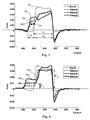
- Curve 13 of the figure 3 represents a signal corresponding to stress measurements for a low running speed of the tire, namely 8 km / h. At this low speed, the presence of a water level on the road has no consequence on the normal stress signal and the signal detected at this speed corresponds to that which can be found on a completely dry road. Thus, when the stress sensor or sensors are outside the direct contact area of the tread with the floor of the roadway, the measured stresses are substantially zero.
- the portion of the curve corresponding to the negative stress measurements corresponds to a section of the tread leaving the crush zone on the ground and taking up the natural curvature of the tire.
- the curves 14, 15 and 16 were obtained experimentally for the same height of water of 2 mm at speeds of 50, 60 and 70 km / h, respectively. These curves have a look substantially different from that of the curve 13. Having recalibrated all the curves at the point where, at the back of the contact area, the stress returns to zero, it is found that the apparent contact area A a is substantially elongated at the beginning of the contact area. A first plate appears whose height increases with speed, it can be estimated that the length of this first plate ⁇ L corresponds to the length of the indirect contact zone A i, that is to say the zone in which a film water is between the tread and the ground. It can also be seen that the length of the direct contact area A d is substantially reduced relative to that of the curve 13.
- the stress is thus always established between the ground and the tread 2 of the tire but via the liquid element constituting the height of water.
- the first plateau obtained on the signal is that of a sensor detecting a stress on the ground via the liquid element corresponding to this height of water.
- This signal therefore represents the resistance opposed by the water to the bread of the tire (hydrostatic pressure), which depends on the running speed according to P ⁇ 1 2 ⁇ ⁇ ⁇ V 2 ( ⁇ : density, V: driving speed).
- the water height present at low speed does not have the effect of presenting the same first plateau on the measured signal because the entry of the sensor into the corresponding volume of water requires a sufficient speed in order to create a tension or a resistance sufficient on the part of the liquid element and therefore a significant constraint.
- the elongation ⁇ L of the contact area is greater than that obtained for a water depth of less than 2 mm because the water depth is frontally in front of the width of the tread of the tire. is more important.
- the contact established by the presence of this liquid medium between the tread of the tire and the floor of the roadway is established higher on the tire so earlier.
- the sensor enters earlier in the portion corresponding to the indirect contact area (because it is done through a film of water) apparent between the ground and the tread 2 of the tire 1.
- the corresponding part of the signal the elongation ⁇ L of the contact area is therefore greater.
- the passage of a tread sensor in the contact area on the floor of the roadway therefore has two parts: a first part corresponding to a contact of the sensor with the floor of the roadway, but via a liquid element (A i ) and a second part corresponding to a direct contact of the sensor with the floor of the roadway (A d ).
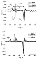
- the figure 5 illustrates calculating a first instantaneous value or criterion ⁇ E used to detect the occurrence of hydroplaning of the invention.
- This figure shows the curves 13d to 16d respectively representing the first derivative of the compression stress measurements according to the value x of the displacement of a sensor in the longitudinal rolling direction X of the tire.
- the curves 13d to 16d correspond to the derivatives of the curves 13 to 16 illustrated in FIG. figure 3 .
- the respective minimums of the stress measurement derivatives are obtained for the measurement index 255, that is to say at the output of the contact area.
- the maximums are obtained during the respective phases of appearance of the trays of constant measurements of the stresses.
- a maximum is obtained as soon as the single plateau appears.
- the value of the first criterion is then ⁇ E 1 .
- curve 14d For a top speed of 50 km / h, curve 14d, there are two positive peaks at the entrance of the contact area corresponding to the two successive fronts of the first and second trays.
- the maximum amplitude peak and the second is the value of ⁇ E is calculated using the second peak.
- the corresponding value of the criterion is slightly lower than the initial value of ⁇ E 1 . There has not been a jump yet.
- ⁇ E l min - l max with l min corresponding to the position where the azimuth of d ⁇ z d x min , and l max corresponding to the position or azimuth of d ⁇ z d x max .
- the first criterion has a value ⁇ E 1 and in the case of the curve 16d, obtained at a speed of 50 km / h, a value ⁇ E 2 .
- the value ⁇ E 2 is very significantly greater than ⁇ E 1 .
- the figure 4 illustrates the calculation of the second criterion or momentary value R z .
- the value of the criterion is -1 since there is only one plate.
- the figure 8 presents the evolution of this second criterion as a function of speed. We see that its value passes gradually from -1 to zero then becomes positive. The zero crossing corresponds to the moment when the compression stresses of the first and second plates become similar, which means that the hydroplaning phenomenon becomes very marked. It is therefore essential to immediately warn the driver of this risk. It is possible to choose as threshold value S 'this zero crossing or a lower value if desired.
- the figure 8 also illustrates the evolution of this second criterion for the two water heights 2 and 8 mm. Unsurprisingly, we find that the higher the speed, the more the influence of the height of water is clear. We also note that beyond the null value of the criterion, the influence of the speed is very marked. A small variation in driving speed can lead to very large variations in the hydroplaning phenomenon.
- a sub-program 23 of the program 11 of the processing unit 8 makes it possible to extract a part of the signal received by the sensors corresponding to a substantially non-zero stress signal, for example typically greater in absolute value. at a threshold.
- the extraction of the part of the signal, for pressure constraints, corresponding to the passage of one or more sensors in the contact area of the tread 2 consists in extracting the signal when the sensor (or sensors) emits a significant signal of stress measurement the duration of this portion of the signal corresponds to the duration of the passage of the sensor in the contact area.
- a data processing is performed for the calculation of ⁇ E criteria and R z (section 26).
- a comparison is then made with thresholds recorded in the data zone 24.
- a first alarm is triggered if a first criterion exceeds a first threshold (section 29) and a second alarm is triggered if a second criterion exceeds a second threshold (section 30). ).
Landscapes
- Engineering & Computer Science (AREA)
- Transportation (AREA)
- Mechanical Engineering (AREA)
- Tires In General (AREA)
- Measuring Fluid Pressure (AREA)
Claims (10)
- Verfahren zur Erfassung eines Aquaplaning-Zustands eines Luftreifens eines Kraftfahrzeugs, der sich auf einem nassen Boden bewegt, wobei der Laufstreifen des Luftreifens mit einem oder mehreren Sensoren (5) ausgestattet ist, von denen jeder die Messung der lokal vom Laufstreifen des Luftreifens erfahrenen Druckbelastung, wenn der Luftreifen auf dem Boden rollt, und die Erzeugung eines diesen Messungen entsprechenden Signals ermöglicht, dadurch gekennzeichnet, dass es die folgenden Schritte aufweist:- Messen der Druckbelastung senkrecht zur Ebene der Straße (σz), wenn der Luftreifen auf dem Boden rollt;- Erzeugen eines diesen Messungen entsprechenden Signals;- Entnahme aus diesem Signal eines Teils bezüglich des Durchgangs des oder der Sensoren durch den scheinbaren Kontaktbereich des Luftreifens auf dem Boden;- Herleiten, von dieser Information, eines Augenblickswerts (ΔE, Rz), der mit dem Vorhandensein einer Zone indirekten Kontakts des scheinbaren Kontaktbereichs des Laufstreifens des Luftreifens auf dem Boden verbunden ist; und- Auslösen eines Alarms, wenn der Augenblickswert eine gegebene Beziehung erfüllt;wobei der Schritt der Herleitung eines Augenblickswerts entspricht:- dem Ableiten des Signals;- der Festlegung des Minimalwerts

 - dem Berechnen des Augenblickswerts ΔE entsprechend der Positionsabweichung zwischen dem Minimal- und dem Maximalwert des abgeleiteten Signals:
- Verfahren nach Anspruch 1, wobei ein Alarm ausgelöst wird, wenn der Augenblickswert ΔE eine gegebene Schwelle überschreitet.
- Verfahren zur Erfassung eines Aquaplaning-Zustands eines Luftreifens eines Fahrzeugs, der sich auf einem nassen Boden bewegt, wobei der Laufstreifen des Luftreifens mit einem oder mehreren Sensoren (5) ausgestattet ist, von denen jeder die Messung der lokal vom Laufstreifen des Luftreifens erfahrenen Druckbelastung, wenn der Luftreifen auf dem Boden rollt, und die Erzeugung eines diesen Messungen entsprechenden Signals ermöglicht, dadurch gekennzeichnet, dass es die folgenden Schritte aufweist:- Messen der Druckbelastung senkrecht zur Ebene der Straße (σz), wenn der Luftreifen auf dem Boden rollt;- Erzeugen eines diesen Messungen entsprechenden Signals;- Entnahme aus diesem Signal eines Teils bezüglich des Durchgangs des oder der Sensoren durch den scheinbaren Kontaktbereich des Luftreifens auf dem Boden;- Herleiten, von dieser Information, eines Augenblickswerts (ΔE, Rz), der mit dem Vorhandensein einer Zone indirekten Kontakts des scheinbaren Kontaktbereichs des Laufstreifens des Luftreifens auf dem Boden verbunden ist; und- Auslösen eines Alarms, wenn der Augenblickswert eine gegebene Beziehung erfüllt;wobei der Schritt der Herleitung eines Augenblickswerts (Rz) entspricht:- wenn der Teil des Signals zwei aufeinanderfolgende Plateaus enthält, der Augenblickswert (Rz) gleich:

ist, wobei σzi die Amplitude der Druckspannungen des ersten Plateaus und σzd die Amplitude der Druckspannungen des zweiten Plateaus darstellt; und- wenn der Teil ein einziges Plateau enthält, der Augenblickswert (Rz) gleich einer Konstanten C ist. - Verfahren nach Anspruch 3, bei dem gilt:

und bei dem C gleich -1 ist. - Verfahren nach Anspruch 3, bei dem gilt:

und bei dem C gleich 0 ist. - Verfahren nach einem der Ansprüche 3 bis 5, wobei ein Alarm ausgelöst wird, wenn der Augenblickswert (Rz) höher als ein gegebener Wert ist.
- Verfahren nach Anspruch 6 in Kombination mit Anspruch 4, wobei ein Alarm ausgelöst wird, wenn der Augenblickswert (Rz) positiv ist.
- Verfahren nach Anspruch 6 in Kombination mit Anspruch 5, wobei ein Alarm ausgelöst wird, wenn der Augenblickswert (Rz) höher als 1 ist.
- Verfahren nach einem der Ansprüche 1 bis 8, wobei nacheinander ein erster Alarm ausgelöst wird, wenn der erste Augenblickswert (ΔE) eine gegebene Schwelle überschreitet, und ein zweiter Alarm höherer Intensität ausgelöst wird, wenn der zweite Augenblickswert (Rz) eine zweite gegebene Schwelle überschreitet.
- Vorrichtung zur Erfassung eines Aquaplaning-Phänomens eines Luftreifens eines Fahrzeugs, der sich auf einem nassen Boden einer Straße bewegt, die aufweist:- einen Luftreifen, von dem ein Laufstreifen mit einem oder mehreren Sensoren (5) ausgestattet ist, von denen jeder die Messung der lokal vom Laufstreifen des Luftreifens beim Rollen auf dem Boden erfahrenen Druckspannungen erlaubt,- Einrichtungen zur Übertragung eines den Messungen dieser Spannungen entsprechenden Signals;- eine Signalverarbeitungseinheit, die aus dem übertragenen Signal einen Signalteil entnehmen kann, der der Anzahl oder der Dauer des Durchgangs des oder der Sensoren durch den Kontaktbereich des Luftreifens beim Rollen auf dem Boden entspricht;dadurch gekennzeichnet, dass sie in der Verarbeitungseinheit ein Programm aufweist, um ausgehend von dem entnommenen Signal das Verfahren nach einem der Ansprüche 1 bis 9 durchzuführen.
Applications Claiming Priority (1)
| Application Number | Priority Date | Filing Date | Title |
|---|---|---|---|
| FR0702575A FR2914744B1 (fr) | 2007-04-06 | 2007-04-06 | Procede de detection d'un phenomene d'hydroplanage d'un pneumatique sur une chaussee |
Publications (2)
| Publication Number | Publication Date |
|---|---|
| EP1977940A1 EP1977940A1 (de) | 2008-10-08 |
| EP1977940B1 true EP1977940B1 (de) | 2013-11-27 |
Family
ID=38663064
Family Applications (1)
| Application Number | Title | Priority Date | Filing Date |
|---|---|---|---|
| EP08154063.5A Not-in-force EP1977940B1 (de) | 2007-04-06 | 2008-04-04 | Verfahren zur Erkennung eines Aquaplaning-Phänomens eines Reifens auf einer Fahrbahn |
Country Status (5)
| Country | Link |
|---|---|
| US (1) | US7832262B2 (de) |
| EP (1) | EP1977940B1 (de) |
| JP (1) | JP5425411B2 (de) |
| CN (1) | CN101281098B (de) |
| FR (1) | FR2914744B1 (de) |
Families Citing this family (10)
| Publication number | Priority date | Publication date | Assignee | Title |
|---|---|---|---|---|
| US7661300B2 (en) * | 2005-03-11 | 2010-02-16 | Michelin Recherche Et Technique S.A. | Flex signature for tire condition |
| FR2914743B1 (fr) * | 2007-04-06 | 2009-05-15 | Michelin Soc Tech | Procede de detection et d'estimation d'un phenomene d'hydroplanage d'un pneumatique sur une chaussee mouillee |
| JP4934185B2 (ja) * | 2009-10-30 | 2012-05-16 | 本田技研工業株式会社 | 車両のスキッド検知装置 |
| JP5018926B2 (ja) * | 2010-04-19 | 2012-09-05 | 株式会社デンソー | 運転補助装置、及びプログラム |
| US10053100B2 (en) * | 2015-10-09 | 2018-08-21 | Cnh Industrial America Llc | Slip control system for an off-road vehicle |
| US11472238B2 (en) | 2017-12-21 | 2022-10-18 | Pirelli Tyre S.P.A. | Method and system for signaling an aquaplane condition of a tyre mounted on a vehicle |
| IT201900014133A1 (it) | 2019-08-06 | 2021-02-06 | Antonio Lupi | Sensore di aquaplaning per qualsiasi tipo di pneumatico |
| US11080949B1 (en) * | 2020-05-04 | 2021-08-03 | Timothy Just | Predictive vehicle operating assistance |
| CN111504666B (zh) * | 2020-05-25 | 2022-05-06 | 中车青岛四方机车车辆股份有限公司 | 一种确定转向架损伤系数的方法及装置 |
| US11774301B2 (en) | 2020-06-16 | 2023-10-03 | The Goodyear Tire & Rubber Company | Tire load estimation system and method |
Family Cites Families (31)
| Publication number | Priority date | Publication date | Assignee | Title |
|---|---|---|---|---|
| US5350035A (en) * | 1991-05-10 | 1994-09-27 | Messerschmitt-Boelkow-Blohm Gmbh | Antihydroplaning system for a motor vehicle |
| JP3052013B2 (ja) * | 1991-10-16 | 2000-06-12 | 本田技研工業株式会社 | ハイドロプレーニング検出装置 |
| DE4242726A1 (de) * | 1992-12-17 | 1994-06-23 | Bert Prof Dr Ing Breuer | Verfahren und Vorrichtung zur Aquaplaning-Erkennung bei Fahrzeugreifen |
| DE4335938A1 (de) * | 1992-12-17 | 1995-04-27 | Continental Ag | Verfahren zur Aquaplaning-Erkennung bei Fahrzeugreifen |
| JP3159596B2 (ja) * | 1994-03-22 | 2001-04-23 | 本田技研工業株式会社 | ハイドロプレーニング現象検出装置 |
| DE19543928C2 (de) * | 1995-11-24 | 1997-09-04 | Daimler Benz Ag | Verfahren zur frühzeitigen Erkennung des Aufschwimmens eines Fahrzeugreifens auf nasser Fahrbahn |
| JP3418121B2 (ja) * | 1997-07-10 | 2003-06-16 | 住友ゴム工業株式会社 | タイヤの摩耗状態検知装置および方法 |
| US5864056A (en) | 1998-02-17 | 1999-01-26 | Bell; Larry D. | Method and apparatus for monitoring the coefficient of friction between a tire and rolling surface, particularly to provide the vehicle operator with coefficient of friction, tire tread wear out and skid warning indications |
| DE19807004A1 (de) | 1998-02-19 | 1999-09-09 | Siemens Ag | Sensorsystem und Verfahren für Überwachung/Messung des Kraftschlusses eines Fahrzeugreifens mit der Fahrbahn und weiterer physikalischer Daten des Reifens |
| US7267148B2 (en) | 1999-08-10 | 2007-09-11 | Michelin Recherche Et Technique S.A. | Measurement of adherence between a vehicle wheel and the roadway |
| BR0002924A (pt) | 1999-08-10 | 2000-10-17 | Michelin Soc Tech | Pneumático e processo de detecção de uma caracterìstica de aderência entre uma roda que possui uma banda de rodagem deformável e um solo de rodagem |
| FR2820501A1 (fr) | 2001-02-07 | 2002-08-09 | Michelin Soc Tech | Mesure d'adherence entre une roue de vehicule et la chaussee |
| EP1259390B1 (de) * | 2000-03-03 | 2008-11-05 | Continental Automotive GmbH | Reifen mit einem sensor sowie verfahren zur bestimmung einer verschleissgrösse eines solchen reifens |
| EP2039540B1 (de) * | 2000-03-16 | 2012-01-11 | Pirelli Tyre S.p.A. | Verfahren zum Bestimmen des Verhaltens eines Reifens in Bewegung |
| DE10025502A1 (de) | 2000-05-23 | 2001-11-29 | Bosch Gmbh Robert | Sensorsystem zur Erfassung von Meßgrößen an einem rotierenden Gegenstand |
| FR2812085B1 (fr) * | 2000-07-20 | 2002-10-25 | Dufournier Technologies S A S | Dispositif et procede de cartographie des effets au sol du passage d'un vehicule |
| JP4606555B2 (ja) | 2000-09-13 | 2011-01-05 | 株式会社ブリヂストン | ハイドロプレーニングの検出方法及びハイドロプレーニング検出装置及び車輌制御装置 |
| DE10060333A1 (de) | 2000-12-04 | 2002-06-13 | Daimler Chrysler Ag | Vorrichtung zur Erkennung einer während des Fahrbetriebes eines Fahrzeuges auftretenden Aquaplaninggefahr |
| DE60231067D1 (de) | 2001-07-10 | 2009-03-19 | Commissariat Energie Atomique | Eine Kraftmesseinrichtung beinhaltender Reifen |
| US6666078B1 (en) * | 2001-12-04 | 2003-12-23 | Dana Corporation | Target tire pressure learning method |
| FR2837748A1 (fr) | 2002-04-02 | 2003-10-03 | Michelin Soc Tech | Pneumatique dote d'une antenne receptrice |
| DE10218781A1 (de) * | 2002-04-26 | 2003-11-13 | Tuev Automotive Gmbh | Auf einer Felge montierbarer Luftreifen, Sensornetz, Umdrehungsmesseinheit und Fahrzeugüberwachungssystem |
| EP1372049A1 (de) * | 2002-06-13 | 2003-12-17 | Société de Technologie Michelin | Servoverfahren zur Aufrechterhaltung des gleitens der Reifen auf einem optimalen Niveau um einen maximalen Reibwert zu erreichen |
| DE10242121B4 (de) | 2002-09-11 | 2017-03-30 | Robert Bosch Gmbh | Fahrzeug mit Aquaplaningerkennung und aktivem Fahrwerk |
| SE0300127D0 (sv) | 2003-01-17 | 2003-01-17 | Imego Ab | Indicator arrangement |
| US7249498B2 (en) | 2003-10-27 | 2007-07-31 | Sumitomo Rubber Industries, Ltd. | System and method for determining tire force |
| JP2005241470A (ja) | 2004-02-26 | 2005-09-08 | Denso Corp | タイヤ作用力検出装置及びタイヤ作用力検出方法 |
| DE102004051654A1 (de) | 2004-10-22 | 2006-04-27 | "Stiftung Caesar" (Center Of Advanced European Studies And Research) | Beschleunigungssensoren im Reifen |
| FR2885409B1 (fr) | 2005-05-04 | 2007-08-31 | Commissariat Energie Atomique | Dispositif de mesure de force a tige rigide |
| JP4747765B2 (ja) * | 2005-09-29 | 2011-08-17 | 株式会社アドヴィックス | 車両のアンチスキッド制御装置 |
| JP2007331659A (ja) | 2006-06-16 | 2007-12-27 | Bridgestone Corp | タイヤ走行状態の推定方法とその装置、及び、センサ付タイヤ |
-
2007
- 2007-04-06 FR FR0702575A patent/FR2914744B1/fr not_active Expired - Fee Related
-
2008
- 2008-04-03 US US12/061,973 patent/US7832262B2/en active Active
- 2008-04-04 EP EP08154063.5A patent/EP1977940B1/de not_active Not-in-force
- 2008-04-04 JP JP2008120703A patent/JP5425411B2/ja not_active Expired - Fee Related
- 2008-04-07 CN CN2008100901568A patent/CN101281098B/zh not_active Expired - Fee Related
Also Published As
| Publication number | Publication date |
|---|---|
| US20080245455A1 (en) | 2008-10-09 |
| CN101281098B (zh) | 2012-09-26 |
| US7832262B2 (en) | 2010-11-16 |
| JP2008273515A (ja) | 2008-11-13 |
| FR2914744A1 (fr) | 2008-10-10 |
| CN101281098A (zh) | 2008-10-08 |
| EP1977940A1 (de) | 2008-10-08 |
| JP5425411B2 (ja) | 2014-02-26 |
| FR2914744B1 (fr) | 2009-07-03 |
Similar Documents
| Publication | Publication Date | Title |
|---|---|---|
| EP1977940B1 (de) | Verfahren zur Erkennung eines Aquaplaning-Phänomens eines Reifens auf einer Fahrbahn | |
| EP1977942B1 (de) | Verfahren zur Erkennung und Abschätzung eines Aquaplaning-Phänomens eines Reifens auf einer nassen Fahrbahn | |
| EP2015206B1 (de) | Verfahren zur Abschätzung der verbleibenden nutzbaren Haftung eines rollenden Reifens | |
| EP2379353B1 (de) | Warnverfahren zur anzeige des verschleisses eines reifens mit einer furche | |
| EP1327131B1 (de) | Verfahren und system oder zentrale zur überwachung des reifenzustandes und zur feststellung der anwesenheit von ketten oder spikes am fahrzeug | |
| EP3083360B1 (de) | Schätzung des haftpotenzials durch beurteilung des rollradius | |
| EP2554443B1 (de) | Vorrichtung und Verfahren zum Bestimmen des Zustands einer Landebahn, Flugzeug mit einer solchen Vorrichtung und Hilfssteuersystem verwendend diesen Landebahnzustand | |
| WO2010106297A1 (fr) | Procede de surveillance de l'etat d'un pneumatique | |
| EP2081781B1 (de) | Verfahren zum anzeigen des von einem reifen erfahrenen alterungsgrads | |
| EP1977941B1 (de) | Abschätzverfahren der Wasserhöhe in Kontakt mit einem Reifen auf einer Fahrbahn | |
| EP1076235B1 (de) | Haftreibungsmessungen zwischen einem Fahrzeugrad und einer Fahrbahn | |
| WO2003070492A2 (fr) | Bandage elastique pour mesurer l'adherence d'un vehicule qui en est equipe sur un sol | |
| WO2006010680A1 (fr) | Estimation du coefficient d'adhérence maximal à partir de la mesure de contraintes dans la bande de roulement d'un pneu | |
| WO2004000620A1 (fr) | Mesure du coefficient d’adherence maximal a partir de la mesure de contraintes dans un bourrelet d’un pneu | |
| EP1953052B1 (de) | Verfahren zur Quantifizierung der Verwendung einer potenziellen maximalen Bodenhaftung eines Reifens | |
| WO2018104679A1 (fr) | Procédé pour obtenir une information redondante de la vitesse d'un véhicule | |
| FR2815712A1 (fr) | Dispositif et procede pour detecter l'adherence d'un pneumatique de vehicule sur le sol, et leurs applications | |
| FR2918455A1 (fr) | Procede de detection d'un glissement local d'un pain de sculpture d'un pneumatique au contact du sol. | |
| EP0380425A1 (de) | Verfahren und Vorrichtung zur Überwachung des Luftdruckes in Fahrzeugreifen | |
| EP4259457A2 (de) | Reifen mit einer lauffläche mit ausgerichteten fasern | |
| FR2918454A1 (fr) | Procede d'estimation de l'adherence globale maximale d'un pneumatique. | |
| FR2924661A1 (fr) | Procede d'estimation d'un angle de derive d'un pneumatique. | |
| FR2904260A1 (fr) | Pneumatique avec un element de bande de roulement calibre |
Legal Events
| Date | Code | Title | Description |
|---|---|---|---|
| PUAI | Public reference made under article 153(3) epc to a published international application that has entered the european phase |
Free format text: ORIGINAL CODE: 0009012 |
|
| AK | Designated contracting states |
Kind code of ref document: A1 Designated state(s): AT BE BG CH CY CZ DE DK EE ES FI FR GB GR HR HU IE IS IT LI LT LU LV MC MT NL NO PL PT RO SE SI SK TR |
|
| AX | Request for extension of the european patent |
Extension state: AL BA MK RS |
|
| 17P | Request for examination filed |
Effective date: 20090408 |
|
| 17Q | First examination report despatched |
Effective date: 20090514 |
|
| AKX | Designation fees paid |
Designated state(s): AT BE BG CH CY CZ DE DK EE ES FI FR GB GR HR HU IE IS IT LI LT LU LV MC MT NL NO PL PT RO SE SI SK TR |
|
| RAP1 | Party data changed (applicant data changed or rights of an application transferred) |
Owner name: MICHELIN RECHERCHE ET TECHNIQUE S.A. Owner name: COMPAGNIE GENERALE DES ETABLISSEMENTS MICHELIN |
|
| GRAP | Despatch of communication of intention to grant a patent |
Free format text: ORIGINAL CODE: EPIDOSNIGR1 |
|
| INTG | Intention to grant announced |
Effective date: 20130823 |
|
| GRAS | Grant fee paid |
Free format text: ORIGINAL CODE: EPIDOSNIGR3 |
|
| GRAA | (expected) grant |
Free format text: ORIGINAL CODE: 0009210 |
|
| AK | Designated contracting states |
Kind code of ref document: B1 Designated state(s): AT BE BG CH CY CZ DE DK EE ES FI FR GB GR HR HU IE IS IT LI LT LU LV MC MT NL NO PL PT RO SE SI SK TR |
|
| REG | Reference to a national code |
Ref country code: GB Ref legal event code: FG4D Free format text: NOT ENGLISH |
|
| REG | Reference to a national code |
Ref country code: CH Ref legal event code: EP |
|
| REG | Reference to a national code |
Ref country code: AT Ref legal event code: REF Ref document number: 642549 Country of ref document: AT Kind code of ref document: T Effective date: 20131215 |
|
| REG | Reference to a national code |
Ref country code: IE Ref legal event code: FG4D Free format text: LANGUAGE OF EP DOCUMENT: FRENCH |
|
| REG | Reference to a national code |
Ref country code: DE Ref legal event code: R096 Ref document number: 602008028950 Country of ref document: DE Effective date: 20140123 |
|
| REG | Reference to a national code |
Ref country code: NL Ref legal event code: VDEP Effective date: 20131127 |
|
| REG | Reference to a national code |
Ref country code: AT Ref legal event code: MK05 Ref document number: 642549 Country of ref document: AT Kind code of ref document: T Effective date: 20131127 |
|
| REG | Reference to a national code |
Ref country code: LT Ref legal event code: MG4D |
|
| PG25 | Lapsed in a contracting state [announced via postgrant information from national office to epo] |
Ref country code: FI Free format text: LAPSE BECAUSE OF FAILURE TO SUBMIT A TRANSLATION OF THE DESCRIPTION OR TO PAY THE FEE WITHIN THE PRESCRIBED TIME-LIMIT Effective date: 20131127 Ref country code: NL Free format text: LAPSE BECAUSE OF FAILURE TO SUBMIT A TRANSLATION OF THE DESCRIPTION OR TO PAY THE FEE WITHIN THE PRESCRIBED TIME-LIMIT Effective date: 20131127 Ref country code: SE Free format text: LAPSE BECAUSE OF FAILURE TO SUBMIT A TRANSLATION OF THE DESCRIPTION OR TO PAY THE FEE WITHIN THE PRESCRIBED TIME-LIMIT Effective date: 20131127 Ref country code: IS Free format text: LAPSE BECAUSE OF FAILURE TO SUBMIT A TRANSLATION OF THE DESCRIPTION OR TO PAY THE FEE WITHIN THE PRESCRIBED TIME-LIMIT Effective date: 20140327 Ref country code: LT Free format text: LAPSE BECAUSE OF FAILURE TO SUBMIT A TRANSLATION OF THE DESCRIPTION OR TO PAY THE FEE WITHIN THE PRESCRIBED TIME-LIMIT Effective date: 20131127 Ref country code: HR Free format text: LAPSE BECAUSE OF FAILURE TO SUBMIT A TRANSLATION OF THE DESCRIPTION OR TO PAY THE FEE WITHIN THE PRESCRIBED TIME-LIMIT Effective date: 20131127 Ref country code: NO Free format text: LAPSE BECAUSE OF FAILURE TO SUBMIT A TRANSLATION OF THE DESCRIPTION OR TO PAY THE FEE WITHIN THE PRESCRIBED TIME-LIMIT Effective date: 20140227 |
|
| PG25 | Lapsed in a contracting state [announced via postgrant information from national office to epo] |
Ref country code: ES Free format text: LAPSE BECAUSE OF FAILURE TO SUBMIT A TRANSLATION OF THE DESCRIPTION OR TO PAY THE FEE WITHIN THE PRESCRIBED TIME-LIMIT Effective date: 20131127 Ref country code: CY Free format text: LAPSE BECAUSE OF FAILURE TO SUBMIT A TRANSLATION OF THE DESCRIPTION OR TO PAY THE FEE WITHIN THE PRESCRIBED TIME-LIMIT Effective date: 20131127 Ref country code: AT Free format text: LAPSE BECAUSE OF FAILURE TO SUBMIT A TRANSLATION OF THE DESCRIPTION OR TO PAY THE FEE WITHIN THE PRESCRIBED TIME-LIMIT Effective date: 20131127 Ref country code: LV Free format text: LAPSE BECAUSE OF FAILURE TO SUBMIT A TRANSLATION OF THE DESCRIPTION OR TO PAY THE FEE WITHIN THE PRESCRIBED TIME-LIMIT Effective date: 20131127 |
|
| PG25 | Lapsed in a contracting state [announced via postgrant information from national office to epo] |
Ref country code: PT Free format text: LAPSE BECAUSE OF FAILURE TO SUBMIT A TRANSLATION OF THE DESCRIPTION OR TO PAY THE FEE WITHIN THE PRESCRIBED TIME-LIMIT Effective date: 20140327 |
|
| PG25 | Lapsed in a contracting state [announced via postgrant information from national office to epo] |
Ref country code: EE Free format text: LAPSE BECAUSE OF FAILURE TO SUBMIT A TRANSLATION OF THE DESCRIPTION OR TO PAY THE FEE WITHIN THE PRESCRIBED TIME-LIMIT Effective date: 20131127 |
|
| REG | Reference to a national code |
Ref country code: DE Ref legal event code: R097 Ref document number: 602008028950 Country of ref document: DE |
|
| PG25 | Lapsed in a contracting state [announced via postgrant information from national office to epo] |
Ref country code: CZ Free format text: LAPSE BECAUSE OF FAILURE TO SUBMIT A TRANSLATION OF THE DESCRIPTION OR TO PAY THE FEE WITHIN THE PRESCRIBED TIME-LIMIT Effective date: 20131127 Ref country code: RO Free format text: LAPSE BECAUSE OF FAILURE TO SUBMIT A TRANSLATION OF THE DESCRIPTION OR TO PAY THE FEE WITHIN THE PRESCRIBED TIME-LIMIT Effective date: 20131127 Ref country code: SK Free format text: LAPSE BECAUSE OF FAILURE TO SUBMIT A TRANSLATION OF THE DESCRIPTION OR TO PAY THE FEE WITHIN THE PRESCRIBED TIME-LIMIT Effective date: 20131127 Ref country code: PL Free format text: LAPSE BECAUSE OF FAILURE TO SUBMIT A TRANSLATION OF THE DESCRIPTION OR TO PAY THE FEE WITHIN THE PRESCRIBED TIME-LIMIT Effective date: 20131127 |
|
| PG25 | Lapsed in a contracting state [announced via postgrant information from national office to epo] |
Ref country code: DK Free format text: LAPSE BECAUSE OF FAILURE TO SUBMIT A TRANSLATION OF THE DESCRIPTION OR TO PAY THE FEE WITHIN THE PRESCRIBED TIME-LIMIT Effective date: 20131127 |
|
| PLBE | No opposition filed within time limit |
Free format text: ORIGINAL CODE: 0009261 |
|
| STAA | Information on the status of an ep patent application or granted ep patent |
Free format text: STATUS: NO OPPOSITION FILED WITHIN TIME LIMIT |
|
| 26N | No opposition filed |
Effective date: 20140828 |
|
| PG25 | Lapsed in a contracting state [announced via postgrant information from national office to epo] |
Ref country code: LU Free format text: LAPSE BECAUSE OF FAILURE TO SUBMIT A TRANSLATION OF THE DESCRIPTION OR TO PAY THE FEE WITHIN THE PRESCRIBED TIME-LIMIT Effective date: 20140404 Ref country code: MC Free format text: LAPSE BECAUSE OF FAILURE TO SUBMIT A TRANSLATION OF THE DESCRIPTION OR TO PAY THE FEE WITHIN THE PRESCRIBED TIME-LIMIT Effective date: 20131127 |
|
| REG | Reference to a national code |
Ref country code: CH Ref legal event code: PL |
|
| REG | Reference to a national code |
Ref country code: DE Ref legal event code: R097 Ref document number: 602008028950 Country of ref document: DE Effective date: 20140828 |
|
| GBPC | Gb: european patent ceased through non-payment of renewal fee |
Effective date: 20140404 |
|
| REG | Reference to a national code |
Ref country code: IE Ref legal event code: MM4A |
|
| PG25 | Lapsed in a contracting state [announced via postgrant information from national office to epo] |
Ref country code: LI Free format text: LAPSE BECAUSE OF NON-PAYMENT OF DUE FEES Effective date: 20140430 Ref country code: CH Free format text: LAPSE BECAUSE OF NON-PAYMENT OF DUE FEES Effective date: 20140430 Ref country code: GB Free format text: LAPSE BECAUSE OF NON-PAYMENT OF DUE FEES Effective date: 20140404 |
|
| PG25 | Lapsed in a contracting state [announced via postgrant information from national office to epo] |
Ref country code: SI Free format text: LAPSE BECAUSE OF FAILURE TO SUBMIT A TRANSLATION OF THE DESCRIPTION OR TO PAY THE FEE WITHIN THE PRESCRIBED TIME-LIMIT Effective date: 20131127 |
|
| PG25 | Lapsed in a contracting state [announced via postgrant information from national office to epo] |
Ref country code: IE Free format text: LAPSE BECAUSE OF NON-PAYMENT OF DUE FEES Effective date: 20140404 |
|
| PG25 | Lapsed in a contracting state [announced via postgrant information from national office to epo] |
Ref country code: MT Free format text: LAPSE BECAUSE OF FAILURE TO SUBMIT A TRANSLATION OF THE DESCRIPTION OR TO PAY THE FEE WITHIN THE PRESCRIBED TIME-LIMIT Effective date: 20131127 |
|
| REG | Reference to a national code |
Ref country code: FR Ref legal event code: PLFP Year of fee payment: 9 |
|
| PG25 | Lapsed in a contracting state [announced via postgrant information from national office to epo] |
Ref country code: BG Free format text: LAPSE BECAUSE OF FAILURE TO SUBMIT A TRANSLATION OF THE DESCRIPTION OR TO PAY THE FEE WITHIN THE PRESCRIBED TIME-LIMIT Effective date: 20131127 |
|
| PG25 | Lapsed in a contracting state [announced via postgrant information from national office to epo] |
Ref country code: GR Free format text: LAPSE BECAUSE OF FAILURE TO SUBMIT A TRANSLATION OF THE DESCRIPTION OR TO PAY THE FEE WITHIN THE PRESCRIBED TIME-LIMIT Effective date: 20140228 |
|
| PG25 | Lapsed in a contracting state [announced via postgrant information from national office to epo] |
Ref country code: HU Free format text: LAPSE BECAUSE OF FAILURE TO SUBMIT A TRANSLATION OF THE DESCRIPTION OR TO PAY THE FEE WITHIN THE PRESCRIBED TIME-LIMIT; INVALID AB INITIO Effective date: 20080404 Ref country code: BE Free format text: LAPSE BECAUSE OF FAILURE TO SUBMIT A TRANSLATION OF THE DESCRIPTION OR TO PAY THE FEE WITHIN THE PRESCRIBED TIME-LIMIT Effective date: 20140430 Ref country code: TR Free format text: LAPSE BECAUSE OF FAILURE TO SUBMIT A TRANSLATION OF THE DESCRIPTION OR TO PAY THE FEE WITHIN THE PRESCRIBED TIME-LIMIT Effective date: 20131127 |
|
| REG | Reference to a national code |
Ref country code: FR Ref legal event code: PLFP Year of fee payment: 10 |
|
| REG | Reference to a national code |
Ref country code: FR Ref legal event code: PLFP Year of fee payment: 11 |
|
| PGFP | Annual fee paid to national office [announced via postgrant information from national office to epo] |
Ref country code: IT Payment date: 20220420 Year of fee payment: 15 Ref country code: FR Payment date: 20220421 Year of fee payment: 15 Ref country code: DE Payment date: 20220420 Year of fee payment: 15 |
|
| REG | Reference to a national code |
Ref country code: DE Ref legal event code: R119 Ref document number: 602008028950 Country of ref document: DE |
|
| PG25 | Lapsed in a contracting state [announced via postgrant information from national office to epo] |
Ref country code: FR Free format text: LAPSE BECAUSE OF NON-PAYMENT OF DUE FEES Effective date: 20230430 Ref country code: DE Free format text: LAPSE BECAUSE OF NON-PAYMENT OF DUE FEES Effective date: 20231103 |
|
| PG25 | Lapsed in a contracting state [announced via postgrant information from national office to epo] |
Ref country code: IT Free format text: LAPSE BECAUSE OF NON-PAYMENT OF DUE FEES Effective date: 20230404 |