EP1977897B1 - Flüssigkeitsübertragungsverfahren und Flüssigkeitsübertragungsvorrichtung - Google Patents
Flüssigkeitsübertragungsverfahren und Flüssigkeitsübertragungsvorrichtung Download PDFInfo
- Publication number
- EP1977897B1 EP1977897B1 EP08005676.5A EP08005676A EP1977897B1 EP 1977897 B1 EP1977897 B1 EP 1977897B1 EP 08005676 A EP08005676 A EP 08005676A EP 1977897 B1 EP1977897 B1 EP 1977897B1
- Authority
- EP
- European Patent Office
- Prior art keywords
- cylinder
- sheet
- liquid
- transfer
- transferred
- Prior art date
- Legal status (The legal status is an assumption and is not a legal conclusion. Google has not performed a legal analysis and makes no representation as to the accuracy of the status listed.)
- Not-in-force
Links
Images

Classifications
-
- B—PERFORMING OPERATIONS; TRANSPORTING
- B41—PRINTING; LINING MACHINES; TYPEWRITERS; STAMPS
- B41F—PRINTING MACHINES OR PRESSES
- B41F23/00—Devices for treating the surfaces of sheets, webs, or other articles in connection with printing
- B41F23/08—Print finishing devices, e.g. for glossing prints
Definitions
- the present invention relates to a liquid transfer method and liquid transfer apparatus which transfer a liquid such as varnish or ink to the two surfaces of a sheet.
- This liquid transfer apparatus comprises a first blanket cylinder (transport cylinder) which holds and conveys a sheet by gripping its one edge, and a second blanket cylinder which opposes the first blanket cylinder. As the sheet passes between the first and second blanket cylinders, varnish is transferred from the second blanket cylinder to the obverse of the sheet, thus coating the obverse of the sheet. Simultaneously, the printing pressure of the second blanket cylinder transfers the varnish from the first blanket cylinder to the reverse of the sheet, thus coating the reverse of the sheet as well.
- overall coating refers to coating of the sheet entirely excluding margins reserved on the leading, trailing, left, and right edges of the sheet.
- overall coating refers to coating that completely covers the images and register marks printed with the ink.
- EP 0 564 856 A1 discloses a method and a device for varnishing and perfecting sheets in a varnishing and perfecting unit.
- a sheet receives a return print on the underside of the sheet in the printing zone after transfer from a feed drum to a back pressure cylinder. Further, a partial varnishing takes place on the face side of a sheet in the region of the printing zone subsequently.
- EP 0 873 867 A2 discloses a coating device for applying varnish to both faces of paper.
- the coating device is provided with a pressure drum for receiving paper from a transfer drum and holding the paper, a first varnish application device for applying varnish to a surface of the paper held by the pressure drum and a second varnish application device which applies the varnish to a rubber blanket on a peripheral face of the pressure drum on an upstream side of a position in which the pressure drum receives the paper.
- the varnish can be applied to the rear face of the paper.
- the present invention has been made to solve this problem and has as its object to prevent the sheet from separating from the transport cylinder, thus improving the transfer quality.
- An upper plate cylinder 1 serves as a varnish supply cylinder (liquid supply cylinder) and is provided with a notch 1a, extending in the axial direction, in part of its circumferential surface.
- a first varnish supply device 2 is a first liquid supply means for supplying varnish to the upper plate cylinder 1, and comprises an upper anilox roller 3 in contact with the upper plate cylinder 1 and a chamber coater 4 which supplies the varnish to the upper anilox roller 3.
- the first varnish supply device 2 and upper plate cylinder 1 constitute a first varnish feeding device (first liquid feeding means) which supplies the varnish to the upper plate cylinder 1.
- An upper blanket cylinder 5 is a printing cylinder serving as a first transfer cylinder, and is in contact with the upper plate cylinder 1 and opposes a blanket cylinder 6 (to be described later).
- the upper blanket cylinder 5 is provided with a notch 5a, extending in the axial direction, in part of its circumferential surface.
- the blanket cylinder 6 is a printing cylinder serving as a transport cylinder.
- the blanket cylinder 6 is provided with a pair of notches 6a, extending in the axial direction, at positions that halve the circumferential surface of the blanket cylinder 6 in the circumferential direction.
- a gripper unit 7 (sheet holding means) which grips and holds the sheet is arranged in each notch 6a.
- a lower plate cylinder 8 serves as a second transfer cylinder in contact with the blanket cylinder 6, and is provided with a notch 8a, extending in the axial direction, in part of its circumferential surface.
- a second varnish supply device 9 is a second liquid supply means for supplying the varnish to the lower plate cylinder 8, and comprises a lower anilox roller 10 in contact with the lower plate cylinder 8, and a chamber coater 11 which supplies the varnish to the lower anilox roller 10.
- the second varnish supply device 9 and lower plate cylinder 8 constitute a second varnish feeding device (second varnish feeding means) which supplies the varnish to the lower plate cylinder 8.
- the upper blanket cylinder 5 opposes the blanket cylinder 6, downstream of an opposing position where an impression cylinder 13 of a printing unit 12 provided upstream of the coating unit opposes the blanket cylinder 6, in the downstream rotational direction of the blanket cylinder 6.
- the lower plate cylinder 8 opposes the blanket cylinder 6, upstream of an opposing position where the impression cylinder 13 of the printing unit 12 opposes the blanket cylinder 6, in the upstream rotational direction of the blanket cylinder 6.
- the varnish supplied from the chamber coater 4 to the upper anilox roller 3 is transferred to the upper blanket cylinder 5 through the upper plate cylinder 1, so that the obverse of printed paper (sheet), passing through the opposing point (nip) where the upper blanket cylinder 5 opposes the blanket cylinder 6, is coated.
- the reverse of the printed sheet is coated with the varnish, transferred from the lower plate cylinder 8 to the circumferential surface of the blanket cylinder 6, by the printing pressure of the upper blanket cylinder 5.
- the sheet with the coated reverse is gripping-changed to the gripper of a delivery chain 14 and conveyed to a sheet delivery device (not shown).
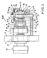
- a first phase adjustment device (first phase adjusting means) 15A provided to the upper plate cylinder 1 and a second phase adjustment device (second phase adjusting means) 15B provided to the lower plate cylinder 8 will be described with reference to Figs. 2 and 3 .
- first and second phase adjustment devices 15A and 15B have the same structure, only the first phase adjustment device 15A will be described, and the second phase adjustment device 15B will be described where necessary.
- an end shaft 1b of the upper plate cylinder 1 is axially supported by an external metal member 17, axially supported by a frame 16 of the printing press, through an internal metal member 18.
- Bolts 20 fix an external gear 19 to the projecting end of the end shaft 1b projecting outside from the frame 16.
- the external gear 19 meshes with an internal gear 21 (to be described later).
- an almost triangular bracket 22 is attached to the frame 16 through a plurality of stays 23 to be parallel to the frame 16.
- a stepped worm wheel 24 is rotatably fitted in a bearing hole 22a of the bracket 22.
- a nut 25 threadably engaging with a threaded portion formed on the distal end of the worm wheel 24 presses a thrust bearing 26 (to be described later) against the bracket 22.
- the thrust bearing 26 and a thrust bearing 27 are interposed on the two sides of the bracket 22 to sandwich it.
- a screw shaft 28 with a flange is inserted in a hole 24a formed in the inner peripheral portion of the worm wheel 24.
- a threaded plate 30 fixed to the worm wheel 24 with a bolt 29 threadably engages with the distal end of a threaded portion 28a of the screw shaft 28.
- a coupling 31 has the internal gear 21 described above on its inner circumferential surface, and a disc 32 is threadably mounted on its one open end.
- One end of the screw shaft 28 described above is fitted in the inner hole of the disc 32.
- the flange of the screw shaft 28 and the nut 33 sandwich the disc 32.
- the flange of the screw shaft 28, the nut 33, and the disc 32 clamp thrust bearings 34 and 35.
- a helical gear 36 is fixed to a flange 31a of the coupling 31 by a ring 37 and bolt 38, and meshes with a drive side helical gear 39. Rotation of the driving side is transmitted to the upper plate cylinder 1 through the helical gears 39 and 36, internal gear 21, and external gear 19. Since the external gear 19 and internal gear 21 slidably mesh with each other and the internal gear 21 has a large face width, even when the coupling 31 moves in the axial direction, the external gear 19 and internal gear 21 do not disengage from each other.
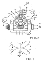
- a bearing box 40 with a box-like shape as shown in Fig. 3 is fixed to the bracket 22 described above.
- a worm 42 meshing with the worm wheel 24 is axially mounted on a worm shaft 41 axially supported by the bearing box 40.
- the worm shaft 41 is connected to a motor (not shown) through a joint 43.
- a linear displacement type potentiometer 45 is fixed to the bracket 46.
- the potentiometer 45 comprises a detection body 48 which is biased in the elongating direction by the spring force of a compression coil spring 47.
- a press body 49 is fixed to the distal end of the screw shaft 28. The upper end of the press body 49 is in contact with the detection body 48. As will be described later, when the screw shaft 28 moves in the axial direction upon phase adjustment of the upper plate cylinder 1, the press body 49 cooperates with the compression coil spring 47 to press the detection body 48.
- the potentiometer 45 detects the forward/backward moving amount of the detection body 48.
- the phase adjustment amount of the upper plate cylinder 1 is calculated from the forward/backward moving amount.
- a panel (not shown) displays the calculated phase adjustment amount.
- the rotation start of that effective impression area 1b of the upper plate cylinder 1, which is continuous to the notch 1a, is positioned upstream of a rotation start of an effective impression area 5b of the upper blanket cylinder 5, which is continuous to the notch 5a, by ⁇ in the rotational direction of the upper plate cylinder 1.
- the lower plate cylinder 8 slightly pivots in the circumferential direction to adjust its phase with respect to the blanket cylinder 6.
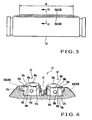
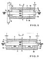
- the mounting structures for blankets 63A and 63B which are mounted on the circumferential surface of the upper plate cylinder 1 and on that of the lower plate cylinder 8 will be described with reference to Figs. 5 and 6 .
- the mounting structure for the upper plate cylinder 1 and that for the lower plate cylinder 8 are identical, only the mounting structure for the varnish supply cylinder blanket (blanket for a liquid supply cylinder) 63A and a varnish supply cylinder sheet member (sheet member for a liquid supply cylinder) 65A which are to be mounted on the upper plate cylinder 1 will be described, and the mounting structure for the second transfer cylinder blanket (blanket for a second transfer cylinder) 63B and a second transfer cylinder sheet member (sheet member for a second transfer cylinder) 65B which are to be mounted on the lower plate cylinder 8 will be described where necessary.
- the upper plate cylinder 1 is provided with a notch 51, extending throughout the entire length of the cylinder, in its circumferential surface.
- a leading edge plate clamp (plate member holding device) 52 and trailing edge plate clamp (plate member holding device) 53 extend in the notch 51 in the axial direction of the cylinder 1 to be parallel to each other.
- the leading edge plate clamp 52 and trailing edge plate clamp 53 are respectively provided with bottom clamping rails 54a and 54b extending in the axial direction of the cylinder 1.
- the bottom clamping rails 54a and 54b are respectively provided with gripping surfaces 55a and 55b and mouthpiece insertion grooves 56a and 56b on their upper surfaces.
- the mouthpiece insertion grooves 56a and 56b continue to the gripping surfaces 55a and 55b, respectively.
- the bottom surfaces of the mouthpiece insertion grooves 56a and 56b are parallel to the gripping surfaces 55a and 55b, respectively, and extend in the axial direction of the cylinder 1.
- Spacers 57a and 57b are fixed to the bottom surfaces of the mouthpiece insertion grooves 56a and 56, respectively.
- the gripper boards 58a and 58b are respectively provided with gripping surfaces 60a and 60b which oppose the gripping surfaces 55a and 55b of the bottom clamping rails 54a and 54b, respectively.
- the distal ends of the gripping surfaces 60a and 60b cover the mouthpiece insertion grooves 56a and 56b, respectively.
- Round rod-like cams 61a and 61b are in contact with the rear ends of the gripper boards 58a and 58b, respectively. When the cams 61a and 61b are pivoted, the gripper boards 58a and 58b swing about the bolts 59a and 59b as swing centers, respectively.
- a case in which the varnish supply cylinder blanket 63A is to be mounted on the upper plate cylinder 1 (or a case in which the second transfer cylinder blanket 63B is to be mounted on the lower plate cylinder 8) will be described.
- a mouthpiece 62a attached to one end of the varnish supply cylinder blanket 63A (or second transfer cylinder blanket 63B) is inserted in the mouthpiece insertion groove 56a of the bottom clamping rail 54a.
- the cam 61a is pivoted so that the distal end of the gripper board 58a covers the mouthpiece insertion groove 56a.
- the distal end of the gripper board 58a urges the mouthpiece 62a to fix it in the mouthpiece insertion groove 56a.
- the varnish supply cylinder blanket 63A (or second transfer cylinder blanket 63B) is wound around the circumferential surface of the upper plate cylinder 1 (or lower plate cylinder 8), and a mouthpiece 62b attached to the other end of the varnish supply cylinder blanket 63A (or second transfer cylinder blanket 63B) is inserted in the mouthpiece insertion groove 56b of the bottom clamping rail 54b.
- the cam 61b is pivoted so that the distal end of the gripper board 58b covers the mouthpiece insertion groove 56b.
- the distal end of the gripper board 58b urges the mouthpiece 62b to fix it in the mouthpiece insertion groove 56b.
- the varnish supply cylinder sheet member 65A is interposed between the varnish supply cylinder blanket 63A and the circumferential surface of the upper plate cylinder 1, and is a so-called blanket underlying member.
- the varnish with the same shape as the outer shape of the varnish supply cylinder sheet member 65A is transferred to the obverse of the sheet, being conveyed by the blanket cylinder 6, through the upper blanket cylinder 5. More specifically, the varnish with the same width as a length W of the varnish supply cylinder sheet member 65A in the widthwise direction is transferred to the obverse of the sheet, and the varnish with the same length as the circumferential length of the varnish supply cylinder sheet member 65A is transferred to the obverse of the sheet.
- the second transfer cylinder sheet member 65B is interposed between the second transfer cylinder blanket 63B and the circumferential surface of the lower plate cylinder 8, and is a so-called blanket underlying member.
- the varnish with the same shape as the outer shape of the second transfer cylinder sheet member 65B is transferred to the reverse of the sheet, being conveyed by the blanket cylinder 6, through the blanket cylinder 6. More specifically, the varnish with the same width as a length W of the second transfer cylinder sheet member 65B in the widthwise direction is transferred to the reverse of the sheet, and the varnish with the same length as the circumferential length of the second transfer cylinder sheet member 65B is transferred to the reverse of the sheet.
- the first phase adjustment device 15A adjusts the phase of the upper plate cylinder 1 to be delayed from the phase of the upper blanket cylinder 5 by ⁇ , and the second phase adjustment device 15B adjusts the phase of the lower plate cylinder 8.
- the first and second varnish feeding devices described above supply the varnish to the upper blanket cylinder 5 and blanket cylinder 6, respectively.
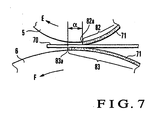
- a leading (downstream in the sheet convey direction or in the direction of an arrow A) margin 70a of an obverse 70A of the sheet 70 which is not coated with the varnish 71 becomes larger by a length ⁇ than a leading margin 70b of a reverse 70B of the sheet 70 which is not coated with the varnish 71.
- a leading edge 72a of a coating region 72 of the obverse 70A of the sheet 70 is positioned on the trailing side (upstream in the sheet convey direction or in the direction of an arrow B) of a leading edge 73a of a coating region 73 of the reverse 70B of the sheet 70 by the length ⁇ .
- the adjustment ranges of the first and second phase adjustment devices 15A and 15B are set such that a minimum value L1min of the length of the leading margin 70a of the obverse 70A of the sheet 70 which is adjusted by the first phase adjustment device 15A becomes lager than a maximum value L2max of the length of the leading margin 70b of the reverse 70B of the sheet 70 which is adjusted by the second phase adjustment device 15B.
- the lengths of the leading margins 70a and 70b refer to the lengths from a leading edge 70c of the sheet 70 to leading edges 72a and 73a of the coating regions (liquid transfer regions) 72 and 73, respectively, in the sheet convey direction.
- the lengths of the trailing margins refer to the lengths from a trailing edge 70d of the sheet 70 to trailing edges 72b and 73b of the coating regions (liquid transfer regions) 72 and 73, respectively, in the sheet convey direction.
- the left and right margin lengths refer to the lengths from left and right trailing edges 70e and 70f of the sheet 70 to left and right trailing edges 72c and 72d and left and right trailing edges 73c and 73d of the coating regions (liquid transfer regions) 72 and 73, respectively, in the direction of sheet width.
- the length of the varnish supply cylinder sheet member 65A in the circumferential direction is smaller than the length of the second transfer cylinder sheet member 65B in the circumferential direction (the directions of the arrows A and B), so that the trailing edge 72b of the coating region 72 of the obverse 70A of the sheet 70 is located closer to the leading side by a length ⁇ than the trailing edge 73b of the coating region 73 of the reverse 70B of the sheet 70.
- the circumferential direction of the varnish supply cylinder sheet member 65A refers to the direction that corresponds to the circumferential direction of the upper plate cylinder 1 when the varnish supply cylinder sheet member 65A is mounted on the upper plate cylinder 1.
- the circumferential direction of the second transfer cylinder sheet member 65B refers to the direction that corresponds to the circumferential direction of the lower plate cylinder 8 when the second transfer cylinder sheet member 65B is mounted on the lower plate cylinder 8.
- the length of the varnish supply cylinder sheet member 65A in the widthwise direction is smaller than that of the second transfer cylinder sheet member 65B in the widthwise direction (the direction perpendicular to the circumferential direction) such that the left and right (in the widthwise direction or directions of arrows C and D) edges 72c and 72d of the coating region 72 of the obverse 70A of the sheet 70 are located within the sheet 70 to be inside the left and right (in the widthwise direction or the directions of arrows C and D) trailing edges 73c and 73d of the coating region 73 of the reverse 70B of the sheet 70 each by a length ⁇ than.
- the widthwise direction of the varnish supply cylinder sheet member 65A refers to the direction that corresponds to the axial direction of the upper plate cylinder 1 when the varnish supply cylinder sheet member 65A is mounted on the upper plate cylinder 1.
- the widthwise direction of the second transfer cylinder sheet member 65B refers to the direction that corresponds to the axial direction of the lower plate cylinder 8 when the second transfer cylinder sheet member 65B is mounted on the lower plate cylinder 8.
- the tackiness of the varnish on the reverse 70B of the sheet 70 serves to prevent the leading edge of the sheet 70 from separating from the blanket cylinder 6 to undesirably stick to the circumferential surface of the upper blanket cylinder 5.
- the blanket cylinder 6 suppresses varnish nonuniformities in the coating region 73 of the reverse 70B of the sheet 70, thus improving the coating quality.
- the varnish is applied to the reverse 70B of the sheet 70 even after it is applied to the obverse 70A of the sheet 70.
- the trailing edge 70d of the sheet 70 passes between the blanket cylinder 6 and upper blanket cylinder 5
- the trailing edge of the obverse 70A of the sheet 70 does not stick to the circumferential surface of the upper blanket cylinder 5.
- the blanket cylinder 6 suppresses varnish nonuniformities in the coating region 73 of the reverse 70B of the sheet 70, thus improving the coating quality.
- the sheet 70 passes between the blanket cylinder 6 and upper blanket cylinder 5, the sheet 70 is coated such that the left and right edges 72c and 72d of the coating region 72 of the obverse 70A of the sheet 70 is located within the sheet 70 to be inside the left and right edges 73c and 73d of the coating region 73 of the reverse 70B of the sheet 70 by the length ⁇ .
- the coating region 73 of the reverse 70B of the sheet 70 is larger than the coating region 72 of the obverse 70A of the sheet 70 in this manner, after the sheet 70 passes between the blanket cylinder 6 and upper blanket cylinder 5, the left and right edges of the obverse 70A of the sheet 70 do not stick to the circumferential surface of the upper blanket cylinder 5.
- the blanket cylinder 6 suppresses varnish nonuniformities in the coating region 73 of the reverse 70B of the sheet 70, thus improving the coating quality.
- varnish (coating liquid) is employed as the liquid to be transferred.
- the present invention can also be applied to ink with a comparatively high viscosity.
- the sheet to which the liquid is to be transferred is exemplified by paper sheet
- the transfer target can be any other sheet.
- a non-rigid sheet such as a synthetic resin film or vinyl film can be employed as the transfer target sheet.
- a phase signifies a position on the cylinder in the rotational direction and is expressed by an angle with respect to the reference position of the cylinder.
Landscapes
- Engineering & Computer Science (AREA)
- Mechanical Engineering (AREA)
- Rotary Presses (AREA)
- Printing Methods (AREA)
- Inking, Control Or Cleaning Of Printing Machines (AREA)
- Decoration By Transfer Pictures (AREA)
- Handling Of Sheets (AREA)
Claims (14)
- Flüssigkeitsübertragungsverfahren, bei dem eine Flüssigkeit auf beide Oberflächen eines Förderbogens übertragen wird, umfassend die Schritte:Fördern des Bogens (70) über einen Transportzylinder (6), der den Bogen hält und fördert, und der einem ersten Übertragungszylinder (5) gegenüberliegt, undÜbertragen einer Flüssigkeit auf eine Oberfläche (70A) des Bogens (70) über den ersten Übertragungszylinder (5); undÜbertragen einer Flüssigkeit auf die andere Oberfläche (70B) des Bogens über den Transportzylinder (6),dadurch gekennzeichnet, dassder Schritt eines Übertragens der Flüssigkeit auf beide Oberflächen des Bogens den Schritt umfasst eines Positionierens einer Kante (72a) eines Bereichs (72), der stromabwärts in einer Bogenförderrichtung gelegen ist, an der einen Oberfläche (70A) des Bogens (70), wo die Flüssigkeit übertragen wird, weiter stromaufwärts in der Bogenförderrichtung von einer Kante (73a) von einem Bereich (73), der in der Bogenförderrichtung stromabwärts gelegen ist, an der andere Oberfläche (70B) des Bogens (70), wo die Flüssigkeit übertragen wird, so dass die Flüssigkeitsübertragung auf die andere Oberfläche (70B) erfolgt, bevor die Flüssigkeitsübertragung auf der einen Oberfläche (70A) stattfindet.
- Verfahren gemäß Anspruch 1, bei dem der Schritt eines Übertragens den Schritt umfasst eines Beschichtens eines gesamten Bereichs (72) von jeder der zwei Oberflächen (70A, B) des Bogens (70) ausgenommen ein Rand (70a, b) unter Verwendung einer Beschichtungsflüssigkeit als die Flüssigkeit.
- Verfahren gemäß Anspruch 1, bei dem der Schritt eines Übertragens den Schritt umfasst eines Positionierens einer Kante (72a) des Bereichs (72) an der einen Oberfläche des Bogens (70A), stromaufwärts in der Bogenförderrichtung gelegen, wo die Flüssigkeit übertragen werden soll, um stromabwärts in der Bogenförderrichtung von einer Kante (73a) des Bereichs (73) an der anderen Oberfläche des Bogens (70B) zu liegen, stromaufwärts in der Bogenförderrichtung gelegen, wo die Flüssigkeit übertragen werden soll.
- Verfahren gemäß Anspruch 1, bei dem der Schritt eines Übertragens weiter umfasst den Schritt eines Positionierens einer Kante des Bereichs an einer Oberfläche des Bogens, in einer Richtung senkrecht zu der Bogenförderrichtung, wo die Flüssigkeit übertragen werden soll, um innerhalb einer Kante des Bereichs an der anderen Oberfläche des Bogens zu liegen, in der Richtung senkrecht zu der Bogenförderrichtung, wo die Flüssigkeit übertragen werden soll.
- Verfahren gemäß Anspruch 1, weiter umfassend den Schritt eines Zuführens der Flüssigkeit zu jedem von dem ersten Übertragungszylinder (5) und dem Transportzylinder (6), so dass eine Kante (82a) eines Bereichs (82) des ersten Übertragungszylinders (5), in einer Drehrichtung stromabwärts gelegen, wo die Flüssigkeit auf den ersten Übertragungszylinder (5) übertragen werden soll, stromaufwärts in der Drehrichtung des ersten Übertragungszylinders (5) angeordnet ist, von einer Kante (83a) eines Bereichs (83) des Transportzylinders (6), stromabwärts in der Drehrichtung gelegen, wo die Flüssigkeit auf den Transportzylinder (6) übertragen werden soll.
- Flüssigkeitsübertragungsvorrichtung, über die Flüssigkeit auf beide Oberflächen von einem Förderbogen übertragen wird, umfassend:einen Transportzylinder (6), der den Bogen hält und fördert, und der einem ersten Transferzylinder (5) gegenüberliegt, undder erste Übertragungszylinder (5) eine Flüssigkeit auf eine Oberfläche (70A) des Bogens (70) überträgt; undder Transportzylinder (6) eine Flüssigkeit auf die andere Oberfläche (70B) des Bogens überträgt,dadurch gekennzeichnet, dass der erste Übertragungszylinder und der Transportzylinder dazu ausgelegt sind, die Flüssigkeit auf beide Oberflächen des Bogens derart zu übertragen, dass eine Kante (72a) von einem Bereich (72), in einer Bogenförderrichtung stromabwärts gelegen, an der einen Oberfläche (70A) des Bogens, wo die Flüssigkeit übertragen wird, weiter stromaufwärts in der Bogenförderrichtung von einer Kante (73a) von einem Bereich (73) gelegen ist, stromabwärts in der Bogenförderrichtung gelegen, an der anderen Oberfläche (70B) des Bogens, wo die Flüssigkeit übertragen wird, so dass die Flüssigkeitsübertragung auf die andere Oberfläche (70B) vor der Flüssigkeitsübertragung auf die eine Oberfläche (70A) erfolgt.
- Vorrichtung gemäß Anspruch 6,
bei der die auf die beiden Oberflächen (70A, B) des Bogens (70) zu übertragende Flüssigkeit eine Beschichtungsflüssigkeit umfasst, und
der erste Übertragungszylinder (5) und der Transportzylinder (6) die Flüssigkeit auf einen gesamten Bereich (72, 73) von jeder der beiden Oberflächen des Bogens ein Rand ausgenommen übertragen. - Vorrichtung gemäß Anspruch 6,
bei der der erste Übertragungszylinder (5) und der Transportzylinder (6) die Flüssigkeit derart übertragen, dass eine Kante von dem Bereich an einer Oberfläche des Bogens, die stromaufwärts in der Bogenförderrichtung gelegen ist, wo die Flüssigkeit übertragen werden soll, stromabwärts in der Bogenförderrichtung von einer Kante von dem Bereich an der anderen Oberfläche des Bogens angeordnet ist, stromabwärts gelegen in der Bogenförderrichtung, wo die Flüssigkeit übertragen werden soll. - Vorrichtung gemäß Anspruch 6, bei der der erste Übertragungszylinder (5) und der Transportzylinder (6) die Flüssigkeit derart übertragen, dass eine Kante von dem Bereich an einer Oberfläche des Bogens, in einer Richtung senkrecht zu der Bogenförderrichtung, wo die Flüssigkeit übertragen werden soll, derart angeordnet ist, um innerhalb einer Kante des Bereichs an der anderen Oberfläche des Bogens zu liegen, in der Richtung senkrecht zu der Bogenförderrichtung, wo die Flüssigkeit übertragen werden soll.
- Vorrichtung gemäß Anspruch 6, weiter umfassend einen Flüssigkeitszuführzylinder (1), der in Kontakt mit dem ersten Übertragungszylinder (5) gelangt, um die Flüssigkeit daran zuzuführen,
wobei eine Phase des Flüssigkeitszuführzylinders zu der von dem ersten Übertragungszylinder verzögert ist. - Vorrichtung gemäß Anspruch 10, weiter umfassend:ein erstes Phasenanpassmittel (15A) zum Anpassen der Phase des Flüssigkeitszuführzylinders bezüglich des ersten Übertragungszylinders,einen zweiten Übertragungszylinder (8), der in Kontakt mit dem Transportzylinder gelangt, um die Flüssigkeit daran zu übertragen, undein zweites Phasenanpassmittel (15B) zum Anpassen einer Phase des zweiten Übertragungszylinders bezüglich des Transportzylinders,wobei das erste Phasenanpassmittel und das zweite Phasenanpassmittel die Phasen derart anpassen, dass ein Minimalwert (L1) von einer Länge eines Randes (70a) der einen Oberfläche des Bogens, die in der Förderrichtung stromabwärts gelegen ist, größer ist als der Maximalwert (L2max) von einer Länge eines Randes (70b) von der anderen Oberfläche des Bogens ist, die in der Förderrichtung stromabwärts gelegen ist.
- Vorrichtung gemäß Anspruch 6, weiter umfassend
ein erstes Flüssigkeitsbeschickungsmittel (1, 2) zum Zuführen der Flüssigkeit auf den ersten Übertragungszylinder (5), und
ein zweites Flüssigkeitsbeschickungsmittel (8, 9) zum Zuführen der Flüssigkeit auf den Transportzylinder (6),
wobei das erste Flüssigkeitsbeschickungsmittel und das zweite Flüssigkeitsbeschickungsmittel jeweils die Flüssigkeit auf den ersten Übertragungszylinder und dem Transportzylinder derart zuführen, dass eine Kante von einem Bereich von dem ersten Übertragungszylinder, die in einer Drehrichtung stromabwärts gelegen ist, wo die Flüssigkeit auf den ersten Übertragungszylinder übertragen werden soll, in der Drehrichtung des ersten Übertragungszylinders stromaufwärts gelegen angeordnet ist, von einer Kante von einem Bereich des Transportzylinders, der in der Drehrichtung stromabwärts gelegen ist, wo die Flüssigkeit auf den Transportzylinder übertragen werden soll. - Vorrichtung gemäß Anspruch 11,
bei der der Flüssigkeitszuführzylinder umfasst:ein Drucktuch (63A) für den Flüssigkeitszuführzylinder, um an einer Umfangsfläche des Flüssigkeitszuführzylinders befestigt zu werden, undein Bogenelement (65A) für den Flüssigkeitszuführzylinder, um zwischen dem Drucktuch für den Flüssigkeitszuführzylinder und der Umfangsfläche des Flüssigkeitszuführzylinders eingelegt zu werden,der zweite Übertragungszylinder ein Drucktuch (63B) für den zweiten Übertragungszylinder umfasst, um an einer Umfangsfläche des zweiten Übertragungszylinders befestigt zu werden, undein Bogenelement (65B) für den zweiten Übertragungszylinder, um zwischen dem Drucktuch für den zweiten Übertragungszylinder und der Umfangsfläche des zweiten Übertragungszylinders eingelegt zu werden, undeine Länge des Bogenelements für den Flüssigkeitszuführzylinder in einer Umfangsrichtung des Flüssigkeitszuführzylinders geringer ist als die des Bogenelements für den zweiten Übertragungszylinder in einer Umfangsrichtung des zweiten Übertragungszylinders. - Vorrichtung gemäß Anspruch 11,
bei der der Flüssigkeitszuführzylinder ein Drucktuch (63A) für den Flüssigkeitszuführzylinder umfasst, um an einer Umfangsfläche des Flüssigkeitszuführzylinders befestigt zu werden, und
ein Bogenelement (65A) für den Flüssigkeitszuführzylinder, um zwischen dem Drucktuch für den Flüssigkeitszuführzylinder und der Umfangsfläche des Flüssigkeitszuführzylinders eingelegt zu werden,
der zweite Übertragungszylinder ein Drucktuch (63b) für den zweiten Übertragungszylinder umfasst, um an einer Umfangsfläche des zweiten Übertragungszylinders befestigt zu werden, und
ein Bogenelement (65B) für den zweiten Übertragungszylinder, um zwischen dem Drucktuch für den zweiten Übertragungszylinder und der Umfangsfläche des zweiten Übertragungszylinders eingelegt zu werden, und
eine Länge des Bogenelements für den Flüssigkeitszuführzylinder in einer axialen Richtung des Flüssigkeitszuführzylinders geringer ist als die von dem Bogenelement für den zweiten Übertragungszylinder in einer axialen Richtung des zweiten Übertragungszylinders.
Applications Claiming Priority (1)
| Application Number | Priority Date | Filing Date | Title |
|---|---|---|---|
| JP2007081309 | 2007-03-27 |
Publications (3)
| Publication Number | Publication Date |
|---|---|
| EP1977897A2 EP1977897A2 (de) | 2008-10-08 |
| EP1977897A3 EP1977897A3 (de) | 2012-01-04 |
| EP1977897B1 true EP1977897B1 (de) | 2013-08-28 |
Family
ID=39708580
Family Applications (1)
| Application Number | Title | Priority Date | Filing Date |
|---|---|---|---|
| EP08005676.5A Not-in-force EP1977897B1 (de) | 2007-03-27 | 2008-03-26 | Flüssigkeitsübertragungsverfahren und Flüssigkeitsübertragungsvorrichtung |
Country Status (4)
| Country | Link |
|---|---|
| US (1) | US8844439B2 (de) |
| EP (1) | EP1977897B1 (de) |
| JP (1) | JP5237660B2 (de) |
| CN (1) | CN101274510B (de) |
Citations (1)
| Publication number | Priority date | Publication date | Assignee | Title |
|---|---|---|---|---|
| EP1319508A1 (de) * | 2001-12-14 | 2003-06-18 | Komori Corporation | Vorrichtung zum Lackieren |
Family Cites Families (5)
| Publication number | Priority date | Publication date | Assignee | Title |
|---|---|---|---|---|
| US2677971A (en) * | 1953-01-06 | 1954-05-11 | Henry B Greenwood | Angular adjustment device |
| DE4211638C2 (de) | 1992-04-07 | 1995-06-29 | Roland Man Druckmasch | Verfahren und Vorrichtung zum Lackieren sowie zum Widerdruck von Bogen in einer Lackiereinheit mit Widerdruckwerk |
| US5350623A (en) * | 1992-09-21 | 1994-09-27 | Derrick Steven L | Compressible blanket assembly |
| JPH10296953A (ja) * | 1997-04-23 | 1998-11-10 | Komori Corp | コーティング装置 |
| DE102004016673B4 (de) | 2004-04-05 | 2006-06-29 | Koenig & Bauer Ag | Bogendruckmaschine für Schön- und Widerdruck |
-
2008
- 2008-03-21 JP JP2008074585A patent/JP5237660B2/ja not_active Expired - Fee Related
- 2008-03-26 US US12/079,571 patent/US8844439B2/en not_active Expired - Fee Related
- 2008-03-26 EP EP08005676.5A patent/EP1977897B1/de not_active Not-in-force
- 2008-03-27 CN CN 200810087879 patent/CN101274510B/zh not_active Expired - Fee Related
Patent Citations (1)
| Publication number | Priority date | Publication date | Assignee | Title |
|---|---|---|---|---|
| EP1319508A1 (de) * | 2001-12-14 | 2003-06-18 | Komori Corporation | Vorrichtung zum Lackieren |
Also Published As
| Publication number | Publication date |
|---|---|
| US20080236420A1 (en) | 2008-10-02 |
| EP1977897A2 (de) | 2008-10-08 |
| CN101274510A (zh) | 2008-10-01 |
| JP2008265314A (ja) | 2008-11-06 |
| US8844439B2 (en) | 2014-09-30 |
| EP1977897A3 (de) | 2012-01-04 |
| CN101274510B (zh) | 2013-05-15 |
| JP5237660B2 (ja) | 2013-07-17 |
Similar Documents
| Publication | Publication Date | Title |
|---|---|---|
| KR100438111B1 (ko) | 매엽지(枚葉紙)인쇄기용압동(壓胴) | |
| US6041706A (en) | Complete release blanket | |
| US7427065B2 (en) | Printer | |
| EP0477283B1 (de) | Zurückziehbare beschichtungsvorrichtung mit gummituchzylinder | |
| US9533486B2 (en) | Printing press for security printing and method for changing a printing forme and printing press start-up | |
| US20120118186A1 (en) | Lateral Correcting Device and Prining Press | |
| US20160129684A1 (en) | Method and device for setting ink-conducting rotational bodies of a printing press | |
| JP2997084B2 (ja) | 印刷用版を湿し印刷するための方法 | |
| JPH0647908A (ja) | 多色刷平版印刷機 | |
| US6272985B1 (en) | Link arm mechanism for adjustable spacing of plate and blanket cylinders in a rotary offset printing press | |
| EP1977897B1 (de) | Flüssigkeitsübertragungsverfahren und Flüssigkeitsübertragungsvorrichtung | |
| US9027475B2 (en) | Method for changing edition on a rotary press | |
| JPH0564880A (ja) | 輪転印刷機の版胴 | |
| US5309839A (en) | Method and apparatus for facilitating the printing of verso sides and the varnishing of recto sides of sheets | |
| JP2001138492A (ja) | 枚葉紙印刷用モジュール式印刷機システム | |
| EP1211069B1 (de) | Druckmaschine | |
| JP4776339B2 (ja) | 印刷機および印刷機の運転方法 | |
| US20110132216A1 (en) | Stack angle compensation arrangement for a skewing adjustment system in an offset printing press | |
| GB2096543A (en) | Adjustments in printing presses | |
| JP3788767B2 (ja) | 版胴 | |
| JPH115291A (ja) | 多色印刷装置および両面印刷方法 | |
| DE102011080321B4 (de) | Greiferanordnung an Bogen führenden Zylindern | |
| US20180361767A1 (en) | Rotogravure unit including a pull roller and narrow-web rotary printing machine | |
| JP2008162283A (ja) | フォイル転写装置を備える枚葉紙印刷機 | |
| JP4414170B2 (ja) | 多色枚葉印刷機 |
Legal Events
| Date | Code | Title | Description |
|---|---|---|---|
| PUAI | Public reference made under article 153(3) epc to a published international application that has entered the european phase |
Free format text: ORIGINAL CODE: 0009012 |
|
| AK | Designated contracting states |
Kind code of ref document: A2 Designated state(s): AT BE BG CH CY CZ DE DK EE ES FI FR GB GR HR HU IE IS IT LI LT LU LV MC MT NL NO PL PT RO SE SI SK TR |
|
| AX | Request for extension of the european patent |
Extension state: AL BA MK RS |
|
| PUAL | Search report despatched |
Free format text: ORIGINAL CODE: 0009013 |
|
| AK | Designated contracting states |
Kind code of ref document: A3 Designated state(s): AT BE BG CH CY CZ DE DK EE ES FI FR GB GR HR HU IE IS IT LI LT LU LV MC MT NL NO PL PT RO SE SI SK TR |
|
| AX | Request for extension of the european patent |
Extension state: AL BA MK RS |
|
| RIC1 | Information provided on ipc code assigned before grant |
Ipc: B41F 23/08 20060101AFI20111125BHEP |
|
| 17P | Request for examination filed |
Effective date: 20120704 |
|
| AKX | Designation fees paid |
Designated state(s): AT BE BG CH CY CZ DE DK EE ES FI FR GB GR HR HU IE IS IT LI LT LU LV MC MT NL NO PL PT RO SE SI SK TR |
|
| GRAP | Despatch of communication of intention to grant a patent |
Free format text: ORIGINAL CODE: EPIDOSNIGR1 |
|
| GRAP | Despatch of communication of intention to grant a patent |
Free format text: ORIGINAL CODE: EPIDOSNIGR1 |
|
| INTG | Intention to grant announced |
Effective date: 20130429 |
|
| GRAS | Grant fee paid |
Free format text: ORIGINAL CODE: EPIDOSNIGR3 |
|
| GRAA | (expected) grant |
Free format text: ORIGINAL CODE: 0009210 |
|
| AK | Designated contracting states |
Kind code of ref document: B1 Designated state(s): AT BE BG CH CY CZ DE DK EE ES FI FR GB GR HR HU IE IS IT LI LT LU LV MC MT NL NO PL PT RO SE SI SK TR |
|
| REG | Reference to a national code |
Ref country code: GB Ref legal event code: FG4D |
|
| REG | Reference to a national code |
Ref country code: CH Ref legal event code: NV Representative=s name: LUCHS AND PARTNER AG PATENTANWAELTE, CH Ref country code: CH Ref legal event code: EP |
|
| REG | Reference to a national code |
Ref country code: AT Ref legal event code: REF Ref document number: 629081 Country of ref document: AT Kind code of ref document: T Effective date: 20130915 |
|
| REG | Reference to a national code |
Ref country code: IE Ref legal event code: FG4D |
|
| REG | Reference to a national code |
Ref country code: DE Ref legal event code: R096 Ref document number: 602008027111 Country of ref document: DE Effective date: 20131024 |
|
| REG | Reference to a national code |
Ref country code: NL Ref legal event code: T3 |
|
| REG | Reference to a national code |
Ref country code: AT Ref legal event code: MK05 Ref document number: 629081 Country of ref document: AT Kind code of ref document: T Effective date: 20130828 |
|
| REG | Reference to a national code |
Ref country code: LT Ref legal event code: MG4D |
|
| PG25 | Lapsed in a contracting state [announced via postgrant information from national office to epo] |
Ref country code: PT Free format text: LAPSE BECAUSE OF FAILURE TO SUBMIT A TRANSLATION OF THE DESCRIPTION OR TO PAY THE FEE WITHIN THE PRESCRIBED TIME-LIMIT Effective date: 20131230 Ref country code: NO Free format text: LAPSE BECAUSE OF FAILURE TO SUBMIT A TRANSLATION OF THE DESCRIPTION OR TO PAY THE FEE WITHIN THE PRESCRIBED TIME-LIMIT Effective date: 20131128 Ref country code: SE Free format text: LAPSE BECAUSE OF FAILURE TO SUBMIT A TRANSLATION OF THE DESCRIPTION OR TO PAY THE FEE WITHIN THE PRESCRIBED TIME-LIMIT Effective date: 20130828 Ref country code: AT Free format text: LAPSE BECAUSE OF FAILURE TO SUBMIT A TRANSLATION OF THE DESCRIPTION OR TO PAY THE FEE WITHIN THE PRESCRIBED TIME-LIMIT Effective date: 20130828 Ref country code: IS Free format text: LAPSE BECAUSE OF FAILURE TO SUBMIT A TRANSLATION OF THE DESCRIPTION OR TO PAY THE FEE WITHIN THE PRESCRIBED TIME-LIMIT Effective date: 20131228 Ref country code: CY Free format text: LAPSE BECAUSE OF FAILURE TO SUBMIT A TRANSLATION OF THE DESCRIPTION OR TO PAY THE FEE WITHIN THE PRESCRIBED TIME-LIMIT Effective date: 20130626 Ref country code: HR Free format text: LAPSE BECAUSE OF FAILURE TO SUBMIT A TRANSLATION OF THE DESCRIPTION OR TO PAY THE FEE WITHIN THE PRESCRIBED TIME-LIMIT Effective date: 20130828 Ref country code: LT Free format text: LAPSE BECAUSE OF FAILURE TO SUBMIT A TRANSLATION OF THE DESCRIPTION OR TO PAY THE FEE WITHIN THE PRESCRIBED TIME-LIMIT Effective date: 20130828 |
|
| PG25 | Lapsed in a contracting state [announced via postgrant information from national office to epo] |
Ref country code: FI Free format text: LAPSE BECAUSE OF FAILURE TO SUBMIT A TRANSLATION OF THE DESCRIPTION OR TO PAY THE FEE WITHIN THE PRESCRIBED TIME-LIMIT Effective date: 20130828 Ref country code: GR Free format text: LAPSE BECAUSE OF FAILURE TO SUBMIT A TRANSLATION OF THE DESCRIPTION OR TO PAY THE FEE WITHIN THE PRESCRIBED TIME-LIMIT Effective date: 20131129 Ref country code: PL Free format text: LAPSE BECAUSE OF FAILURE TO SUBMIT A TRANSLATION OF THE DESCRIPTION OR TO PAY THE FEE WITHIN THE PRESCRIBED TIME-LIMIT Effective date: 20130828 Ref country code: SI Free format text: LAPSE BECAUSE OF FAILURE TO SUBMIT A TRANSLATION OF THE DESCRIPTION OR TO PAY THE FEE WITHIN THE PRESCRIBED TIME-LIMIT Effective date: 20130828 Ref country code: LV Free format text: LAPSE BECAUSE OF FAILURE TO SUBMIT A TRANSLATION OF THE DESCRIPTION OR TO PAY THE FEE WITHIN THE PRESCRIBED TIME-LIMIT Effective date: 20130828 Ref country code: BE Free format text: LAPSE BECAUSE OF FAILURE TO SUBMIT A TRANSLATION OF THE DESCRIPTION OR TO PAY THE FEE WITHIN THE PRESCRIBED TIME-LIMIT Effective date: 20130828 |
|
| PG25 | Lapsed in a contracting state [announced via postgrant information from national office to epo] |
Ref country code: CY Free format text: LAPSE BECAUSE OF FAILURE TO SUBMIT A TRANSLATION OF THE DESCRIPTION OR TO PAY THE FEE WITHIN THE PRESCRIBED TIME-LIMIT Effective date: 20130828 |
|
| PG25 | Lapsed in a contracting state [announced via postgrant information from national office to epo] |
Ref country code: CZ Free format text: LAPSE BECAUSE OF FAILURE TO SUBMIT A TRANSLATION OF THE DESCRIPTION OR TO PAY THE FEE WITHIN THE PRESCRIBED TIME-LIMIT Effective date: 20130828 Ref country code: EE Free format text: LAPSE BECAUSE OF FAILURE TO SUBMIT A TRANSLATION OF THE DESCRIPTION OR TO PAY THE FEE WITHIN THE PRESCRIBED TIME-LIMIT Effective date: 20130828 Ref country code: DK Free format text: LAPSE BECAUSE OF FAILURE TO SUBMIT A TRANSLATION OF THE DESCRIPTION OR TO PAY THE FEE WITHIN THE PRESCRIBED TIME-LIMIT Effective date: 20130828 Ref country code: SK Free format text: LAPSE BECAUSE OF FAILURE TO SUBMIT A TRANSLATION OF THE DESCRIPTION OR TO PAY THE FEE WITHIN THE PRESCRIBED TIME-LIMIT Effective date: 20130828 Ref country code: RO Free format text: LAPSE BECAUSE OF FAILURE TO SUBMIT A TRANSLATION OF THE DESCRIPTION OR TO PAY THE FEE WITHIN THE PRESCRIBED TIME-LIMIT Effective date: 20130828 |
|
| PG25 | Lapsed in a contracting state [announced via postgrant information from national office to epo] |
Ref country code: IT Free format text: LAPSE BECAUSE OF FAILURE TO SUBMIT A TRANSLATION OF THE DESCRIPTION OR TO PAY THE FEE WITHIN THE PRESCRIBED TIME-LIMIT Effective date: 20130828 Ref country code: ES Free format text: LAPSE BECAUSE OF FAILURE TO SUBMIT A TRANSLATION OF THE DESCRIPTION OR TO PAY THE FEE WITHIN THE PRESCRIBED TIME-LIMIT Effective date: 20130828 |
|
| REG | Reference to a national code |
Ref country code: DE Ref legal event code: R097 Ref document number: 602008027111 Country of ref document: DE |
|
| PLBE | No opposition filed within time limit |
Free format text: ORIGINAL CODE: 0009261 |
|
| STAA | Information on the status of an ep patent application or granted ep patent |
Free format text: STATUS: NO OPPOSITION FILED WITHIN TIME LIMIT |
|
| 26N | No opposition filed |
Effective date: 20140530 |
|
| REG | Reference to a national code |
Ref country code: DE Ref legal event code: R097 Ref document number: 602008027111 Country of ref document: DE Effective date: 20140530 |
|
| REG | Reference to a national code |
Ref country code: NL Ref legal event code: V1 Effective date: 20141001 |
|
| PG25 | Lapsed in a contracting state [announced via postgrant information from national office to epo] |
Ref country code: LU Free format text: LAPSE BECAUSE OF FAILURE TO SUBMIT A TRANSLATION OF THE DESCRIPTION OR TO PAY THE FEE WITHIN THE PRESCRIBED TIME-LIMIT Effective date: 20140326 |
|
| REG | Reference to a national code |
Ref country code: CH Ref legal event code: PL |
|
| GBPC | Gb: european patent ceased through non-payment of renewal fee |
Effective date: 20140326 |
|
| REG | Reference to a national code |
Ref country code: FR Ref legal event code: ST Effective date: 20141128 |
|
| REG | Reference to a national code |
Ref country code: IE Ref legal event code: MM4A |
|
| PG25 | Lapsed in a contracting state [announced via postgrant information from national office to epo] |
Ref country code: CH Free format text: LAPSE BECAUSE OF NON-PAYMENT OF DUE FEES Effective date: 20140331 Ref country code: FR Free format text: LAPSE BECAUSE OF NON-PAYMENT OF DUE FEES Effective date: 20140331 Ref country code: IE Free format text: LAPSE BECAUSE OF NON-PAYMENT OF DUE FEES Effective date: 20140326 Ref country code: LI Free format text: LAPSE BECAUSE OF NON-PAYMENT OF DUE FEES Effective date: 20140331 Ref country code: GB Free format text: LAPSE BECAUSE OF NON-PAYMENT OF DUE FEES Effective date: 20140326 |
|
| PG25 | Lapsed in a contracting state [announced via postgrant information from national office to epo] |
Ref country code: NL Free format text: LAPSE BECAUSE OF NON-PAYMENT OF DUE FEES Effective date: 20141001 |
|
| PG25 | Lapsed in a contracting state [announced via postgrant information from national office to epo] |
Ref country code: MT Free format text: LAPSE BECAUSE OF FAILURE TO SUBMIT A TRANSLATION OF THE DESCRIPTION OR TO PAY THE FEE WITHIN THE PRESCRIBED TIME-LIMIT Effective date: 20130828 |
|
| PG25 | Lapsed in a contracting state [announced via postgrant information from national office to epo] |
Ref country code: BG Free format text: LAPSE BECAUSE OF FAILURE TO SUBMIT A TRANSLATION OF THE DESCRIPTION OR TO PAY THE FEE WITHIN THE PRESCRIBED TIME-LIMIT Effective date: 20130828 Ref country code: MC Free format text: LAPSE BECAUSE OF FAILURE TO SUBMIT A TRANSLATION OF THE DESCRIPTION OR TO PAY THE FEE WITHIN THE PRESCRIBED TIME-LIMIT Effective date: 20130828 |
|
| PG25 | Lapsed in a contracting state [announced via postgrant information from national office to epo] |
Ref country code: TR Free format text: LAPSE BECAUSE OF FAILURE TO SUBMIT A TRANSLATION OF THE DESCRIPTION OR TO PAY THE FEE WITHIN THE PRESCRIBED TIME-LIMIT Effective date: 20130828 Ref country code: HU Free format text: LAPSE BECAUSE OF FAILURE TO SUBMIT A TRANSLATION OF THE DESCRIPTION OR TO PAY THE FEE WITHIN THE PRESCRIBED TIME-LIMIT; INVALID AB INITIO Effective date: 20080326 |
|
| PGFP | Annual fee paid to national office [announced via postgrant information from national office to epo] |
Ref country code: DE Payment date: 20190312 Year of fee payment: 12 |
|
| REG | Reference to a national code |
Ref country code: DE Ref legal event code: R119 Ref document number: 602008027111 Country of ref document: DE |
|
| PG25 | Lapsed in a contracting state [announced via postgrant information from national office to epo] |
Ref country code: DE Free format text: LAPSE BECAUSE OF NON-PAYMENT OF DUE FEES Effective date: 20201001 |