EP1975013B1 - Airbag-Klammer / -Befestigung - Google Patents
Airbag-Klammer / -Befestigung Download PDFInfo
- Publication number
- EP1975013B1 EP1975013B1 EP08005259A EP08005259A EP1975013B1 EP 1975013 B1 EP1975013 B1 EP 1975013B1 EP 08005259 A EP08005259 A EP 08005259A EP 08005259 A EP08005259 A EP 08005259A EP 1975013 B1 EP1975013 B1 EP 1975013B1
- Authority
- EP
- European Patent Office
- Prior art keywords
- fastener
- members
- air bag
- arm
- installation
- Prior art date
- Legal status (The legal status is an assumption and is not a legal conclusion. Google has not performed a legal analysis and makes no representation as to the accuracy of the status listed.)
- Not-in-force
Links
- 238000009434 installation Methods 0.000 claims description 48
- 239000000463 material Substances 0.000 claims description 9
- 238000000034 method Methods 0.000 claims description 9
- 238000004891 communication Methods 0.000 claims description 3
- 238000005452 bending Methods 0.000 claims description 2
- 238000012790 confirmation Methods 0.000 description 4
- 230000000007 visual effect Effects 0.000 description 4
- 238000000465 moulding Methods 0.000 description 2
- 239000004952 Polyamide Substances 0.000 description 1
- 230000000712 assembly Effects 0.000 description 1
- 238000000429 assembly Methods 0.000 description 1
- 238000013037 co-molding Methods 0.000 description 1
- 238000010276 construction Methods 0.000 description 1
- 230000005489 elastic deformation Effects 0.000 description 1
- 238000001746 injection moulding Methods 0.000 description 1
- 239000002184 metal Substances 0.000 description 1
- 239000002991 molded plastic Substances 0.000 description 1
- 229920002647 polyamide Polymers 0.000 description 1
- 238000004080 punching Methods 0.000 description 1
- 238000000926 separation method Methods 0.000 description 1
Images


Classifications
-
- B—PERFORMING OPERATIONS; TRANSPORTING
- B60—VEHICLES IN GENERAL
- B60R—VEHICLES, VEHICLE FITTINGS, OR VEHICLE PARTS, NOT OTHERWISE PROVIDED FOR
- B60R21/00—Arrangements or fittings on vehicles for protecting or preventing injuries to occupants or pedestrians in case of accidents or other traffic risks
- B60R21/02—Occupant safety arrangements or fittings, e.g. crash pads
- B60R21/16—Inflatable occupant restraints or confinements designed to inflate upon impact or impending impact, e.g. air bags
- B60R21/20—Arrangements for storing inflatable members in their non-use or deflated condition; Arrangement or mounting of air bag modules or components
-
- F—MECHANICAL ENGINEERING; LIGHTING; HEATING; WEAPONS; BLASTING
- F16—ENGINEERING ELEMENTS AND UNITS; GENERAL MEASURES FOR PRODUCING AND MAINTAINING EFFECTIVE FUNCTIONING OF MACHINES OR INSTALLATIONS; THERMAL INSULATION IN GENERAL
- F16B—DEVICES FOR FASTENING OR SECURING CONSTRUCTIONAL ELEMENTS OR MACHINE PARTS TOGETHER, e.g. NAILS, BOLTS, CIRCLIPS, CLAMPS, CLIPS OR WEDGES; JOINTS OR JOINTING
- F16B21/00—Means for preventing relative axial movement of a pin, spigot, shaft or the like and a member surrounding it; Stud-and-socket releasable fastenings
- F16B21/09—Releasable fastening devices with a stud engaging a keyhole slot
Definitions
- the present disclosure relates to automobile air bag fasteners and a method for installing fasteners to connect automobile vehicle air bag assemblies.
- fasteners are used to join the air bag directly to a vehicle panel or to a trim piece which is subsequently installed to sections or metal body portions of the automobile.
- Common fasteners used for these applications have a torque applied to the fastener which is remotely connected to an information collection device such as a computer, which receives an indication of the torque applied. When a predetermined torque value is indicated, an auditable record is generated of the completed installation of the fastener.
- Drawbacks of the torque fastener are the costs of the fastener and the need for both the torque application tool and the electronic circuitry required to record the torque signal. Also, remote indication of a correctly applied torque does not by itself ensure that the fastener and therefore the air bag have been installed in the correct location in the vehicle.
- Clip fasteners have been substituted for the above torque fasteners due to their reduced costs and simplified installation.
- Clip fasteners are commonly made of molded plastic material. When the clip fastener is made of a polymeric material and is not installed using an electrically connected torque driver, an auditable electronic record of clip fastener installation is commonly not available. A visual, auditable confirmation of correct installation of each clip fastener is therefore required.
- Known clip fasteners do not provide for ease of installation and a visual, auditable confirmation of their correct installation.
- Document WO 2005/022019 A1 discloses a clip for retaining films, flat-strip cables or the like.
- the clip is constituted of a lower part and an upper part connected by a hinge member, the first and second parts adapted to rotate from a fastener open condition to engage each other into a fastener closed position, the fastener closed position being adapted to have an airbag member positioned between the first and second part, and an arm extending from the second part and adapted to rotate with respect to the second part, the arm extending from the second part in the fastener closed condition and operable to engage the second part.
- an airbag installation fastener includes first and second fastener members connected by a hinge member.
- the first and second fastener members are adapted to rotate from a fastener open condition to engage each other in a fastener closed position.
- the fastener closed position provides for an air bag member positioned between the first and second fastener members.
- Each of the first and second fastener members has an aperture adapted to receive a vehicle connected stud to support both the airbag installation fastener and the air bag member from the stud.
- An arm extending from the second fastener member is adapted to rotate with respect to the second fastener member. The arm extends from the second fastener member in the fastener closed condition and is operable to both engage the second fastener member and to abut the stud to visually indicate a fastener completed installation condition.
- the body includes first and second fastener members and a hinge member between the first and second fastener members.
- At least one deflectable engagement post homogenously extends from one of the first and second fastener members.
- the other one of the first and second fastener members has an aperture adapted to receive the engagement post to engage the first and second fastener members.
- a hinge pin homogenously connected to the second fastener member is received in a hinge pin aperture of a hinge arm homogenously connected to the first fastener member.
- the first and second fastener members are adapted to rotate from the fastener open condition to a fastener closed condition frangibly disconnecting the hinge pin from the hinge arm.
- the fastener closed condition has the first and second fastener members engaged to each other by the engagement post and adapted to receive an air bag member between the first and second fastener members.
- a second fastener member adapted to engage the first fastener member has a recessed surface adapted to receive the raised surface of the first fastener member.
- the first and second fastener members are adapted to receive an air bag member having an aperture aligned with respect to the raised surface when the raised surface is received in the recessed surface.
- a method for installing an airbag installation fastener is provided.
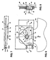
- Figure 1 is a top perspective view of an air bag bracket/fastener of the present disclosure in a fully open condition
- Figure 2 is a bottom perspective view of the air bag bracket/fastener of Figure 1 ;
- Figure 3 is a bottom plan view of the air bag bracket/fastener of Figure 1 ;
- Figure 4 is a side elevational view of the air bag bracket/fastener of Figure 3 ;
- Figure 5 is an end elevational view of the air bag bracket/fastener of Figure 3 ;
- Figure 6 is a top plan view of a fully installed air bag bracket/fastener of the present disclosure with respect to an extending portion of an air bag;
- Figure 7 is a side elevational view of the fully installed air bag bracket/fastener of Figure 6 ;
- Figure 8 is a cross sectional end elevational view taken at section 8 of Figure 6 ;
- Figure 9 is a cross sectional side elevational view taken at section 9 of Figure 6 ;
- Figure 10 is a cross sectional side elevational view taken at section 10 of Figure 6 ;
- Figure 11 is a bottom perspective view of a partially installed air bag bracket/fastener of the present disclosure with respect to an extending portion of an air bag;
- Figure 12 is a bottom perspective view of a fully installed air bag bracket/fastener of the present disclosure with respect to an extending portion of an air bag;
- Figure 13 is a top perspective view of the fully installed air bag bracket/fastener of Figure 12 .
- an air bag bracket fastener 10 molded as a single homogenous part or body from a polymeric material includes a first fastener member 12 and a second fastener member 14 separated by a hinge section 16.
- First fastener member 12 includes a deflectable engagement post 18 which is received through a post receiving aperture 20 provided in second fastener member. 14 to engage first fastener member 12 to second fastener member 14 in a fastener closed condition (shown in reference to Figures 6-8 ).
- Second fastener member 14 includes a second deflectable engagement post 22 which is received and engaged to first fastener member 12 at a post receiving aperture or slot 24 of first body member 12.
- a deflectable catch arm 26 extends laterally away from second body member 14.
- the first and second fastener members 12, 14, the hinge member 16, and the deflectable catch arm 26 are all homogenously joined in a fastener open condition shown, defined as an as-molded condition of bracket fastener 10.
- First fastener member 12 further includes a raised engagement ring 28 having a plurality of radially extending keys 29 which can be equidistantly spaced about a perimeter of raised engagement ring 28.
- Raised engagement ring 28 is adapted to be received within a recessed receiving ring 30 of second fastener member 14.
- a plurality of key slots 31 substantially equivalent in size and spacing to the radially extending keys 29 are also positioned about recessed receiving ring 30 and are adapted to receive individual ones of the radially extending keys 29 when raised engagement ring 28 is received within recessed receiving ring 30.
- Bracket fastener 10 can be changed from the fully open extended position to a closed condition by rotating first fastener member 12 towards second fastener member 14 about hinge section 16 in a fastener closing direction "A" until a first body surface 32 of first fastener member 12 substantially contacts a second body surface 33 of second fastener member 14.
- first fastener member 12 further includes a first keyway aperture 34
- second fastener member 14 includes a similarly sized second keyway aperture 35.
- first and second keyway apertures 34, 35 are co-axially aligned with each other.
- a raised perimeter wall 36 is provided about a perimeter of first fastener member 12 opposite to first body surface 32
- a similar raised perimeter wall 38 is provided about a perimeter of second body member 14 opposite to second body surface 33.
- Raised perimeter walls 36, 38 are provided to increase the stiffness of each of first and second fastener members 12, 14.
- Deflectable catch arm 26 is homogenously connected to second body member 14 at a bending and attachment location 40.
- a free end of deflectable catch arm 26 includes a first keyhole post 42 and a second keyhole post 44.
- First and second keyhole posts 42, 44 are spaced from each other and adapted to be lockingly engaged within second keyway aperture 35 as will be described in better detail in reference to Figure 6 .
- Items 28', 30' refer to opposite faces of raised engagement ring 28 and recessed receiving ring 30, respectively.
- hinge section 16 includes each of a first and second hinge arm 46, 48 homogenously extending from first body member 12.
- a first and second hinge pin 50, 52 are received within each of first and second hinge arms 46, 48 respectively.
- First and second hinge pins 50, 52 are homogenously connected to a hinge extending member 54 which homogenously extends from second fastener member 14.
- First keyway aperture 34 of first body member 12 includes a substantially circular aperture portion 56 having an elongated slot 58 in communication therewith.
- a deflectable tab 60 extends partially into circular aperture portion 56.
- a raised slot wall 62 extends substantially about each of circular aperture portion 56 and elongated slot 58 to provide increased stiffness in the area of circular aperture portion 56.
- Second keyway aperture 35 of second fastener member 14 includes a second circular aperture portion 64 and a second elongated slot 66 in communication therewith.
- a ramped member 67 is created on a face 68 of second fastener member 14. Ramped member 67 is substantially flush with face 68 where it is proximately located with respect to second circular aperture portion 64 and increases gradually in height and away from face 68 as it extends in a direction of second elongated slot 66 and away from second circular aperture portion 64.
- Deflectable catch arm 26 also includes a semi-circular free end 69 where first and second keyhole posts 42, 44 are homogeneously connected.
- a semi-circular notch 70 is also created in semi-circular free end 69 which is oriented to open in the same direction as second elongated slot 66 extends.
- Bracket fastener 10 in the fastener open condition has a total fastener length "B” and a total fastener width "C". According to several embodiments of the present disclosure, total fastener length "B" is approximately 162.3 mm, and total fastener width "C" is approximately 42.3 mm.
- each of first and second keyhole posts 42, 44 include a ramped barb end 72, 74, respectively.
- First and second keyhole posts 42, 44 homogenously extend from a first face 76 of an enhanced thickness portion 78 of deflectable catch arm 26.
- Enhanced thickness portion 78 is connected to second fastener member 14 by a reduced thickness portion 80 which allows deflectable catch arm 26 to rotate with respect to second fastener member 14.
- Deflectable engagement post 18 and second deflectable engagement post 22 have barbed ends which extend opposite to or away from each other.
- Second deflectable engagement post 22 includes a ramped barb 82 and similarly, deflectable engagement post 18 includes a ramped barb 84.
- a post-to-post dimension "D" is maintained between distal ends of each of first and second keyhole posts 42, 44 and distal ends of each of deflectable engagement post 18 and second deflectable engagement post 22.
- post-to-post dimension "D" is approximately 12.1 mm.
- hinge section 16 Each of first and second hinge pins 50, 52 have a substantially triangular shape. First and second hinge pins 50, 52 are received in and co-molded with a triangular shaped aperture 86 of both first and second hinge arms 46, 48. Material flashing 87 created by molding gates when hinge section 16 is molded is frangible when first and second fastener members 12, 14 are rotated towards each other, breaking the homogenously joined condition of the as-molded body of bracket fastener 10. With specific reference to Figure 5 , post-to-post total dimension "D" defines the portion having a largest depth of bracket fastener 10.
- Bracket fastener 10 is used by sandwiching an extending portion 88 of an air bag 89 between each of first and second fastener members 12, 14.
- the air bag 89 includes an aperture (not visible in these views) which is aligned with the raised engagement ring 28 and the air bag 89 is partially engaged by the plurality of radially extending keys 29.
- First and second fastener members 12, 14 are then rotated about hinge section 16 to engage them using engagement post 18 and second deflectable engagement post 22 with the air bag extending portion 88 sandwiched in between.
- Bracket fastener 10 together with extending portion 88 of air bag 89 form a sub-assembly which can be assembled for example by an air bag manufacturer or supplier.
- the fastener/air bag sub-assembly can be shipped for example to an automobile manufacturer or component installer wherein the sub-assembly of bracket fastener 10 and air bag 89 are installed for example onto a T-stud fastener 90 having a fastener head 92.
- a perimeter edge 94 of ramped member 67 extends beyond a fastener head diameter "F" of fastener head 92 such that pulling bracket fastener 10 and air bag 89 in a direction "Z" with respect to T-stud 90 frictionally engages fastener head 92 onto ramped member 67 with sufficient clearance to allow for individual variations in thickness of air bag 89 and construction tolerances of bracket fastener 10.
- the completed or fully installed position is defined when deflectable catch arm 26 is rotated about reduced thickness portion 80 and first and second keyhole posts 42, 44 (not visible in this view) are engaged within second keyway aperture 35 of second body member 14.
- a radius "G" of semi-circular notch 70 formed in semi-circular free end 69 positions semi-circular notch 70 proximate to or in abutment with a portion of fastener head 92 which acts as a redundant locking member to prevent removal of bracket fastener 10.
- deflectable tab 60 and deflectable catch arm 26 prevent motion of T-stud 90 in a release direction "K".
- a clearance "J" can also be provided between deflectable catch arm 26 and fastener head 92.
- a shank 96 of T-stud 90 is commonly attached to a vehicle panel 98 using a connection joint 100 such as a welded joint.
- T-stud 90 can also be attached to vehicle panel 98 in other ways including but not limited to a threaded connection, or a thread and nut combination.
- an assembled fastener thickness "H” is approximately 11.2 mm. It is also noted that the triangular points or ends of each of first and second hinge pins 50, 52 are each frictionally engaged with one of a plurality of inner walls 101 defined by triangular-shaped aperture 86. This frictional engagement also provides resistance to separation of first and second body members 12, 14.
- fastener head 92 of T-stud 90 abuts a raised surface 102 of ring 30'.
- Shank 96 is received within each of elongated slot 58 and second elongated slot 66.
- An aperture is created by cutting, punching, or similar removal technique to remove material from extending portion 88 of air bag 89.
- This aperture has a diameter substantially equal to or larger than a diameter of raised engagement ring 28 so that extending portion 88 is disposed between first and second fastener members 12, 14 with the aperture overlapped and engaged by radially extending keys 29 (not shown in this view).
- a cavity 103 is therefore provided between first and second body members 12, 14 where material of air bag 89 is not present between raised engagement ring 28 and recessed receiving ring 30. Cavity 103 provides clearance for installation of bracket fastener 10 about T-stud 90 as well as installation of first and second keyhole posts 42, 44 in second circular aperture portion 64.
- ramped barb 82 of second deflectable engagement post 22 includes a ramped surface 104.
- Ramped surface 104 allows second deflectable engagement post 22 to elastically deflect in an installation deflection direction "L”.
- ramped barb 84 of deflectable engagement post 18 also has a ramped surface 106 which allows deflectable engagement post 18 to elastically deflect in an installation deflection direction "M”.
- bracket fastener 10 with respect to air bag 89 is shown.
- This sub-assembly can be completed for example at an air bag manufacturer by partial installation of bracket fastener 10 with respect to extending portion 88 of air bag 89.
- the sub-assembly is completed by rotating first and second fastener members 12, 14 until the two body members are engaged to each other using deflectable engagement post 18 and second deflectable engagement post 22 (not clearly visible in this view).
- Deflectable catch arm 26 remains in its extended position shown. This sub-assembly of components can then be shipped to an installer of air bag 89.
- bracket fastener 10 when the sub-assembly as shown in Figure 11 is received by an installer of air bag 89, the installation of bracket fastener 10 can be continued by inserting bracket fastener 10 over the fastener head 92 of T-stud 90 which elastically deflects deflectable tab 60 (away from the viewer as shown in Figure 12 ) to allow fastener head 92 to be received within circular aperture portion 56. By then pulling both bracket fastener 10 and air bag 89 in an installation direction "N" with respect to T-stud 90, shank 96 is positioned within elongated slot 58 as shown. Second deflectable engagement post 22 and second keyhole post 44 are also shown in their snap engaged positions.
- deflectable catch arm 26 is rotated at reduced thickness portion 80 until semi-circular free end 69 is positioned as shown having semi-circular notch 70 positioned proximate to (i.e.: in a side-by-side configuration with) fastener head 92 which provides visual confirmation that the assembly is complete as well as preventing motion of bracket fastener 10 in either of the installation direction "N" or a removal direction "P".
- the position of semi-circular, free end 69 as shown therefore provides an auditable indication of a complete and correct installation of bracket fastener 10.
- Air bag bracket fasteners 10 of the present disclosure can be made of one or more polymeric materials suitable for molding for example by an injection molding process.
- bracket fastener 10 is made using a polyamide 6-6 material.
- T-studs used in applications for bracket fasteners 10 of the present disclosure can have a shank diameter of approximately 5 mm and a head diameter of approximately 9 mm. These dimensions and the other dimensions defined herein are not limiting to the present disclosure and can vary at the discretion of the manufacturer to suit different quantities or sizes of T-studs, or different attachment fasteners such as screws, bolts, and the like.
- Air bag bracket fasteners of the present disclosure offer several advantages. By co-molding each of the body members, hinge portion, and catch arm, a fastener is created which tends to remain in a fully open or extended position until the body members are rotated. Once rotated to a closed condition, the barbed posts and the interference or friction between the triangular-shaped hinge pins and the corresponding walls of the hinge pin apertures act to resist re-opening of the fastener after an air bag extending portion is engaged between the body members. By combining keyway apertures with a deflectable tab, when the fasteners of the present disclosure engage a fastener such as a T-stud, the fastener further resists removal.
- a fastener such as a T-stud
- the catch arm with a corresponding T-stud notch of the present disclosure used as a final installation step provides both a visual confirmation of a completed fastener installation, as well as a redundant locking member to further resist removal or re-opening of the air bag bracket fastener.
- the keys and corresponding key slots of the present disclosure provide for engagement of the air bag extending portion both before and after the air bag bracket fastener is closed.
Landscapes
- Engineering & Computer Science (AREA)
- Mechanical Engineering (AREA)
- Air Bags (AREA)
Claims (14)
- Airbaginstallations-Befestigungseinrichtung (10) mit:einem ersten und einem zweiten Befestigungseinrichtungs-Glied (12, 14), die mittels eines Gelenkgliedes (16) miteinander verbunden sind, wobei das erste und das zweite Befestigungseinrichtungs-Glied (12, 14) dazu ausgelegt sind, von einem Befestigungseinrichtungs-Offenzustand zum Eingriff aneinander in eine Befestigungseinrichtungs-Geschlossenposition zu rotieren, wobei ein Airbagglied (88) eines Airbags (89) in der Befestigungseinrichtungs-Geschlossenposition zwischen dem ersten und dem zweiten Befestigungseinrichtungs-Glied (12, 14) positioniert werden kann, wobei jedes des ersten und des zweiten Befestigungseinrichtungs-Gliedes (12, 14) eine Öffnung (34, 35) aufweist, die dazu ausgelegt ist, einen mit einem Fahrzeug verbundenen Bolzen (90) aufzunehmen, um sowohl die Airbaginstallations-Befestigungseinrichtung (10) als auch das Airbagglied (88) an dem Bolzen (90) zu lagern, undeinem Arm (26), der sich von dem zweiten Befestigungseinrichtungs-Glied (14) erstreckt und dazu ausgelegt ist, in Bezug auf das zweite Befestigungseinrichtungs-Glied (14) zu rotieren, wobei der Arm (26) sich in dem Befestigungseinrichtungs-Geschlossenzustand von dem zweiten Befestigungseinrichtungs-Glied (14) erstreckt und betriebsbereit ist, sowohl an dem zweiten Befestigungseinrichtungs-Glied (14) anzugreifen als auch an dem Bolzen (90) anzustoßen, um einen vervollständigten Befestigungseinrichtungs-Installationszustand visuell anzuzeigen.
- Airbaginstallations-Befestigungseinrichtung nach Anspruch 1, ferner mit:einem erhabenen Eingriffsring (28) des ersten Befestigungseinrichtungs-Gliedes (12), wobei der erhabene Eingriffsring (28) die Öffnung (34) aufweist, die sich durch den erhabenen Eingriffsring (28) hindurch erstreckt; undeinem ausgenommenen Aufnahmering (30) des zweiten Befestigungseinrichtungs-Gliedes (14), wobei der ausgenommene Aufnahmering (30) dazu ausgelegt ist, den erhabenen Eingriffsring (28) in der Befestigungseinrichtungs-Geschlossenposition aufzunehmen.
- Airbaginstallations-Befestigungseinrichtung nach Anspruch 2, ferner mit:einer Vielzahl von Nasen (29), die sich von dem erhabenen Eingriffsring (28) in radialer Richtung erstrecken, undeiner Vielzahl von Nasenschlitzen (31), die in dem ausgenommenen Aufnahmering (30) ausgebildet und so angeordnet sind, dass sie einzelnen der Nasen (29) des erhabenen Eingriffsrings (28) in der Befestigungseinrichtungs-Geschlossenposition entsprechen und diese aufnehmen,wobei das Airbagglied (88) eine Öffnung aufweist, die mit dem erhabenen Eingriffsring (28) ausgerichtet ist, und wobei das Airbagglied (88) von der Vielzahl von Nasen (29) teilweise ergriffen ist.
- Airbaginstallations-Befestigungseinrichtung nach einem der Ansprüche 1 - 3, wobei der Arm (26) aufweist:wenigstens ein Hakenelement (42, 44), das dazu ausgelegt ist, in der Öffnung (35) des zweiten Befestigungseinrichtungs-Gliedes (14) aufgenommen zu werden; undeine Auskerbung (70), die dazu ausgelegt ist, einen Kopf des Bolzens (90), zumindest teilweise aufzunehmen, wobei die Auskerbung (70) in einer Konfiguration seitlich in Bezug auf den Bolzen (90) angeordnet ist, was eine Sichtbarkeit des Bolzens (90) und des Arms (26) in dem vervollständigten Installationszustand ermöglicht.
- Airbaginstallations-Befestigungseinrichtung nach einem der Ansprüche 1 - 4, wobei der Arm (26) einen Abschnitt (80) erster Dicke und einen Abschnitt (78) zweiter Dicke aufweist, wobei der Abschnitt (80) erster Dicke homogen mit dem zweiten Befestigungseinrichtungs-Glied (14) verbunden ist und dünner ist als der Abschnitt (78) zweiter Dicke, um ein Biegen des Arms (26) in dem Abschnitt (80) erster Dicke zu unterstützen, wobei der Abschnitt (78) zweiter Dicke sich frei von dem zweiten Befestigungseinrichtungs-Glied (14) weg erstreckt.
- Airbaginstallations-Befestigungseinrichtung nach einem der Ansprüche 1 - 5, wobei das erste Befestigungseinrichtungs-Glied (12) ein sich erstreckendes auslenkbares Glied (18) aufweist, das ein Hakenende besitzt, das dazu ausgelegt ist, in einer Öffnung (20) des zweiten Befestigungseinrichtungs-Gliedes (14) aufgenommen zu werden, um das erste und das zweite Befestigungseinrichtungs-Glied (12, 14) in der Befestigungseinrichtungs-Geschlossenposftion in Eingriff zu bringen.
- Airbaginstallations-Befestigungseinrichtung nach einem der Ansprüche 1 - 6, wobei das zweite Befestigungseinrichtungs-Glied (14) ein sich erstreckendes auslenkbares Glied (22) aufweist, das ein Hakenende besitzt, das dazu ausgelegt ist, in einem Schlitz (24) des ersten Befestigungseinrichtungs-Gliedes (12) aufgenommen zu werden, um das erste und das zweite Befestigungseinrichtungs-Glied (12, 14) in der Befestigungseinrichtungs-Geschlossenposition miteinander in Eingriff zu bringen.
- Airbaginstallations-Befestigungseinrichtung nach einem der Ansprüche 1 - 7, wobei jede der ersten und der zweiten Öffnung (34, 35) eine Schlüsselnutausnehmung definiert, die eine im Wesentlichen kreisförmige Öffnung (56, 64) in Verbindung mit einem länglichen Schlitz (58, 66) aufweist
- Airbaginstallations-Befestigungseinrichtung nach einem der Ansprüche 1 - 8, wobei das erste und das zweite Befestigungseinrichtungs-Glied (12, 14), das Gelenkglied (16) und der Arm (26) in dem Befestigungseinrichtungs-Offenzustand sämtlich homogen miteinander verbunden sind und aus einem formbaren Polymermaterial hergestellt sind.
- Airbaginstallations-Befestigungseinrichtung nach einem der Ansprüche 1 - 9, wobei das wenigstens eine Hakenelement (42, 44) ein erstes und ein zweites Hakenelement (42, 44) aufweist, die einander gegenüberliegen, wobei jedes des ersten und des zweiten Hakenelementes (42, 44) eine Auflauffläche aufweist, die betriebsbereit ist, um eine Auslenkung des ersten und des zweiten Hakenelementes (42, 44) zu unterstützen.
- Airbaganordnung mit einem Airbag (89) und einer Airbaginstallations-Befestigungseinrichtung nach einem der Ansprüche 1 bis 10.
- Verfahren zum Installieren einer Airbaginstallations-Befestigungseinrichtung (10), wobei die Airbaginstallations-Befestigungseinrichtung (10) einen Polymerkörper aufweist, der in einem Befestigungseinrichtungs-Offenzustand homogen miteinander verbundene Glieder aufweist, wobei der Körper ein erstes und ein zweites Befestigungseinrichtungs-Glied (12, 14) aufweist, die durch ein Gelenkglied (16) miteinander verbunden sind, wobei der Körper einen erhabenen Eingriffsring (28) des ersten Befestigungseinrichtungs-Gliedes (12) aufweist, wobei der Körper einen ausgenommenen Ring (30) des zweiten Befestigungseinrichtungs-Gliedes (14) aufweist, wobei der Körper eine auslenkbare Eingriffssäule (18, 22) aufweist, die sich homogen von einem des ersten und des zweiten Befestigungseinrichtungs-Gliedes (12, 14) erstreckt, und wobei der Körper ein Armglied (26) aufweist, das sich homogen von dem zweiten Befestigungseinrichtungs-Glied (14) erstreckt, wobei das Verfahren aufweist:Rotieren des ersten und des zweiten Befestigungseinrichtungs-Gliedes (12, 14) aufeinander zu um das Gelenkglied (16) herum, bis die auslenkbare Eingriffssäule (18, 22) von einer Öffnung (20, 24) des anderen von erstem und zweitem Befestigungseinrichtungs-Glied (12, 14) aufgenommen ist, um das erste und das zweite Befestigungseinrichtungs-Glied (12, 14) miteinander in Eingriff zu bringen, wobei ein Airbagglied (88) sandwichartig dazwischen aufgenommen ist,Anbringen des ersten und des zweiten Befestigungseinrichtungs-Gliedes (12, 14), und zwar mit dem sandwichartig dazwischen aufgenommenen Airbagglied (88), an einem mit einem Fahrzeug verbundenen Befestigungseinrichtungs-Glied (90), undVerschwenken des Armgliedes (26), so dass das Armglied (26) an dem zweiten Befestigungseinrichtungs-Glied (14) angreift und um das Armglied (26) in der Nachbarschaft des mit dem Fahrzeug verbundenen Befestigungseinrichtungs-Gliedes (90) zu positionieren, um eine vervollständigte Installation der Airbaginstallations-Befestigungseinrichtung (10) visuell anzuzeigen.
- Verfahren nach Anspruch 12, ferner mit dem Schritt des Ausrichtens einer Öffnung des Airbaggliedes (88) mit dem erhabenen Eingriffsring (28), und zwar vor dem Rotationsschritt.
- Verfahren nach Anspruch 12 oder 13, ferner mit dem Schritt, einen Gelenkstift (50, 52) homogen mit dem zweiten Befestigungseinrichtungs-Glied (14) zu verbinden, wobei der Gelenkstift (50, 52) dazu ausgelegt ist, in einer Gelenkstiftöffnung eines Gelenkarms (46, 48) aufgenommen zu werden, der homogen mit dem ersten Befestigungseinrichtungs-Glied (12) verbunden ist.
Applications Claiming Priority (2)
| Application Number | Priority Date | Filing Date | Title |
|---|---|---|---|
| US92060907P | 2007-03-29 | 2007-03-29 | |
| US12/041,906 US7669883B2 (en) | 2007-03-29 | 2008-03-04 | Air bag bracket/fastener |
Publications (3)
| Publication Number | Publication Date |
|---|---|
| EP1975013A2 EP1975013A2 (de) | 2008-10-01 |
| EP1975013A3 EP1975013A3 (de) | 2010-12-01 |
| EP1975013B1 true EP1975013B1 (de) | 2013-02-27 |
Family
ID=39535271
Family Applications (1)
| Application Number | Title | Priority Date | Filing Date |
|---|---|---|---|
| EP08005259A Not-in-force EP1975013B1 (de) | 2007-03-29 | 2008-03-20 | Airbag-Klammer / -Befestigung |
Country Status (3)
| Country | Link |
|---|---|
| US (1) | US7669883B2 (de) |
| EP (1) | EP1975013B1 (de) |
| JP (2) | JP5349824B2 (de) |
Cited By (1)
| Publication number | Priority date | Publication date | Assignee | Title |
|---|---|---|---|---|
| EP3156668A1 (de) | 2015-10-15 | 2017-04-19 | Newfrey LLC | Befestigungsklammer und befestigungsverfahren |
Families Citing this family (8)
| Publication number | Priority date | Publication date | Assignee | Title |
|---|---|---|---|---|
| US7861384B2 (en) * | 2004-09-06 | 2011-01-04 | Takata-Petri Ag | Airbag arrangement and tools |
| US7887086B2 (en) * | 2008-09-12 | 2011-02-15 | Key Safety Systems, Inc. | Curtain air bag module and mounting clip |
| DE102009011481B4 (de) * | 2009-03-06 | 2015-02-19 | Autoliv Development Ab | Befestigungsbeschlag und Befestigungsvorrichtung zur Befestigung eines Airbags an einer Fahrzeugstruktur |
| DE102009022322A1 (de) * | 2009-05-22 | 2010-11-25 | Daimler Ag | Verfahren zum Befestigen eines Halteelements eines Airbags |
| DE102009022323A1 (de) * | 2009-05-22 | 2010-11-25 | Daimler Ag | Airbagbefestigungsvorrichtung mit Schieber |
| US10093239B2 (en) * | 2014-11-12 | 2018-10-09 | Ford Global Technologies Llc | Retention feature for snap-in attachments |
| US9505368B2 (en) | 2015-02-27 | 2016-11-29 | Tk Holdings Inc. | Fastener and fastening system for an airbag assembly |
| CA2991497A1 (en) | 2015-07-07 | 2017-01-12 | Toyota Boshoku America, Inc. | Mistake proof brackets for installation of seat trim cover airbag strip to a seat frame |
Family Cites Families (108)
| Publication number | Priority date | Publication date | Assignee | Title |
|---|---|---|---|---|
| JPS36022343B1 (de) * | 1959-12-24 | 1961-11-18 | Univ Tokyo | |
| US3638640A (en) * | 1967-11-01 | 1972-02-01 | Robert F Shaw | Oximeter and method for in vivo determination of oxygen saturation in blood using three or more different wavelengths |
| JPS4812001U (de) * | 1971-06-21 | 1973-02-10 | ||
| US4142383A (en) * | 1977-08-17 | 1979-03-06 | Eberhart Glass Blowing Ltd. | Liquid filled sealed glass ornament and method |
| JPS5813190Y2 (ja) * | 1979-01-23 | 1983-03-14 | 北川工業株式会社 | フラットケ−ブル押え具 |
| USRE32361E (en) * | 1979-05-14 | 1987-02-24 | Medtronic, Inc. | Implantable telemetry transmission system for analog and digital data |
| JPS56125515U (de) * | 1980-02-27 | 1981-09-24 | ||
| US4326535A (en) * | 1980-05-13 | 1982-04-27 | Akron City Hospital | Circuit and method for the radiotelemetry of esophageal pH in an ECG radiotelemetry system |
| US4523279A (en) * | 1980-11-24 | 1985-06-11 | Oximetrix, Inc. | Apparatus for determining oxygen saturation levels in blood |
| US4431004A (en) * | 1981-10-27 | 1984-02-14 | Bessman Samuel P | Implantable glucose sensor |
| US5186172A (en) * | 1982-03-22 | 1993-02-16 | Mountpelier Investments, S.A. | Remote sensing tonometric catheter apparatus |
| US4571292A (en) * | 1982-08-12 | 1986-02-18 | Case Western Reserve University | Apparatus for electrochemical measurements |
| US4571589A (en) * | 1982-11-22 | 1986-02-18 | Cordis Corporation | Biomedical implant with high speed, low power two-way telemetry |
| WO1984002839A1 (en) * | 1983-01-21 | 1984-08-02 | Ramm Associates | Implantable hyperthermia device and system |
| US4961422A (en) * | 1983-01-21 | 1990-10-09 | Marchosky J Alexander | Method and apparatus for volumetric interstitial conductive hyperthermia |
| US4575676A (en) * | 1983-04-04 | 1986-03-11 | Advanced Research And Applications Corporation | Method and apparatus for radiation testing of electron devices |
| US4655880A (en) * | 1983-08-01 | 1987-04-07 | Case Western Reserve University | Apparatus and method for sensing species, substances and substrates using oxidase |
| US4519401A (en) * | 1983-09-20 | 1985-05-28 | Case Western Reserve University | Pressure telemetry implant |
| US4638436A (en) * | 1984-09-24 | 1987-01-20 | Labthermics Technologies, Inc. | Temperature control and analysis system for hyperthermia treatment |
| US4642463A (en) * | 1985-01-11 | 1987-02-10 | Thoms William H | Intelligent radiation monitor |
| US4651741A (en) * | 1985-05-30 | 1987-03-24 | Baxter Travenol Laboratories, Inc. | Method and apparatus for determining oxygen saturation in vivo |
| US5012411A (en) * | 1985-07-23 | 1991-04-30 | Charles J. Policastro | Apparatus for monitoring, storing and transmitting detected physiological information |
| DK334787A (da) * | 1986-07-01 | 1988-01-02 | Terumo Corp | Apparat til maaling af biologisk information |
| US5083031A (en) * | 1986-08-19 | 1992-01-21 | International Sensor Technology, Inc. | Radiation dosimeters |
| DE3700119A1 (de) * | 1987-01-03 | 1988-07-14 | Inst Diabetestechnologie Gemei | Implantierbarer elektrochemischer sensor |
| US4804847A (en) * | 1987-01-27 | 1989-02-14 | Medrad, Inc. | Radiation detector with an ionizable gas atop an integrated circuit |
| US4935345A (en) * | 1987-04-07 | 1990-06-19 | Arizona Board Of Regents | Implantable microelectronic biochemical sensor incorporating thin film thermopile |
| US4750495A (en) * | 1987-06-05 | 1988-06-14 | Medtronic, Inc. | Oxygen sensing pacemaker |
| US4796641A (en) * | 1987-07-06 | 1989-01-10 | Data Sciences, Inc. | Device and method for chronic in-vivo measurement of internal body pressure |
| US4913153A (en) * | 1987-11-13 | 1990-04-03 | Florida International University | Personal dosimeter |
| US4989601A (en) * | 1988-05-02 | 1991-02-05 | Medical Engineering & Development Institute, Inc. | Method, apparatus, and substance for treating tissue having neoplastic cells |
| US4900422A (en) * | 1988-07-05 | 1990-02-13 | Bryan Avron I | System for monitoring and reporting the operability and calibration status of a dissolved oxygen sensor |
| US5098547A (en) * | 1988-10-11 | 1992-03-24 | Bryan Avron I | Dissolved oxygen sensor calibration, monitoring and reporting system |
| US6219573B1 (en) * | 1989-04-14 | 2001-04-17 | Exergen Corporation | Radiation detector probe |
| US5193538A (en) * | 1989-02-14 | 1993-03-16 | Siemens Aktiengesellschaft | In vivo implantable medical device with battery monitoring circuitry |
| US5127404A (en) * | 1990-01-22 | 1992-07-07 | Medtronic, Inc. | Telemetry format for implanted medical device |
| US5109850A (en) * | 1990-02-09 | 1992-05-05 | Massachusetts Institute Of Technology | Automatic blood monitoring for medication delivery method and apparatus |
| DE4015264C1 (de) * | 1990-05-12 | 1991-07-18 | Schott Glaswerke | |
| US5117113A (en) * | 1990-07-06 | 1992-05-26 | Thompson And Nielson Electronics Ltd. | Direct reading dosimeter |
| WO1992000766A1 (en) * | 1990-07-06 | 1992-01-23 | Iit Research Institute | Method and apparatus for rendering medical materials safe |
| US5252962A (en) * | 1990-08-03 | 1993-10-12 | Bio Medic Data Systems | System monitoring programmable implantable transponder |
| KR930002824B1 (ko) * | 1990-08-21 | 1993-04-10 | 손병기 | 감이온 전계효과 트랜지스터를 이용한 바이오 센서용 측정회로 |
| US5117824A (en) * | 1990-11-14 | 1992-06-02 | Medtronic, Inc. | Apparatus for monitoring electrical physiologic signals |
| JP2646848B2 (ja) * | 1990-11-30 | 1997-08-27 | 日本電気株式会社 | グルコースセンサの測定方法 |
| US5205294A (en) * | 1991-02-19 | 1993-04-27 | Pacific Communications, Inc. | Apparatus and methodology for digital telemetry of biomedical signals |
| US5318023A (en) * | 1991-04-03 | 1994-06-07 | Cedars-Sinai Medical Center | Apparatus and method of use for a photosensitizer enhanced fluorescence based biopsy needle |
| US5377676A (en) * | 1991-04-03 | 1995-01-03 | Cedars-Sinai Medical Center | Method for determining the biodistribution of substances using fluorescence spectroscopy |
| GB9107751D0 (en) * | 1991-04-12 | 1991-05-29 | Elopak Systems | Treatment of material |
| DE4139122C1 (de) * | 1991-11-28 | 1993-04-08 | Fenzlein, Paul-Gerhard, 8500 Nuernberg, De | |
| US5178404A (en) * | 1992-01-09 | 1993-01-12 | Johnson Chen | Contraction controller for collapsible type contractible baggage cart |
| US5400382A (en) * | 1992-04-19 | 1995-03-21 | Alpha Omega Technologies, Inc. | Automated irradiator for the processing of products and a method of operation |
| US5355880A (en) * | 1992-07-06 | 1994-10-18 | Sandia Corporation | Reliable noninvasive measurement of blood gases |
| US5676651A (en) * | 1992-08-06 | 1997-10-14 | Electric Boat Corporation | Surgically implantable pump arrangement and method for pumping body fluids |
| US5330634A (en) * | 1992-08-28 | 1994-07-19 | Via Medical Corporation | Calibration solutions useful for analyses of biological fluids and methods employing same |
| US5620479A (en) * | 1992-11-13 | 1997-04-15 | The Regents Of The University Of California | Method and apparatus for thermal therapy of tumors |
| US5383909A (en) * | 1993-01-29 | 1995-01-24 | Medtronic, Inc. | Diagnostic telemetry system for an apparatus for detection and treatment of tachycardia and fibrillation |
| US5324315A (en) * | 1993-08-12 | 1994-06-28 | Medtronic, Inc. | Closed-loop downlink telemetry and method for implantable medical device |
| US5497772A (en) * | 1993-11-19 | 1996-03-12 | Alfred E. Mann Foundation For Scientific Research | Glucose monitoring system |
| NL9400534A (nl) * | 1994-04-05 | 1995-11-01 | Rijksuniversiteit | Systeem voor het bepalen van een samenstelling van radionucliden. |
| US5507786A (en) * | 1994-04-14 | 1996-04-16 | Pacesetter, Inc. | System and method for measuring and storing parametric data pertaining to operating characteristics of an implantable medical device |
| US5493825A (en) * | 1994-04-19 | 1996-02-27 | Clear-Deck Systems, Inc. | Light-transmissive decking assembly |
| SE9401402D0 (sv) * | 1994-04-25 | 1994-04-25 | Siemens Elema Ab | Medicinskt implantat |
| US5626862A (en) * | 1994-08-02 | 1997-05-06 | Massachusetts Institute Of Technology | Controlled local delivery of chemotherapeutic agents for treating solid tumors |
| US5626630A (en) * | 1994-10-13 | 1997-05-06 | Ael Industries, Inc. | Medical telemetry system using an implanted passive transponder |
| US5591217A (en) * | 1995-01-04 | 1997-01-07 | Plexus, Inc. | Implantable stimulator with replenishable, high value capacitive power source and method therefor |
| US5606163A (en) * | 1995-01-11 | 1997-02-25 | The United States Of America As Represented By The Secretary Of The Navy | All-optical, rapid readout, fiber-coupled thermoluminescent dosimeter system |
| US5620472A (en) * | 1995-01-12 | 1997-04-15 | Pacesetter, Inc. | Apparatus and method for dynamically interpreting and displaying a real-time telemetry link |
| US5593430A (en) * | 1995-01-27 | 1997-01-14 | Pacesetter, Inc. | Bus system for interconnecting an implantable medical device with a plurality of sensors |
| ES2112069T3 (es) * | 1995-02-04 | 1998-03-16 | Baumann & Haldi Sa | Sistema individual de medida, de tratamiento y de transmision de parametros esencialmente fisiologicos. |
| US5596199A (en) * | 1995-02-06 | 1997-01-21 | Clemson University | Passive solid state microdosimeter with electronic readout |
| US5517313A (en) * | 1995-02-21 | 1996-05-14 | Colvin, Jr.; Arthur E. | Fluorescent optical sensor |
| US5633161A (en) * | 1995-03-29 | 1997-05-27 | Millennium Pharmaceuticals, Inc. | Murine gene fomy030 coding for tumor progression inhibitor |
| US5759199A (en) * | 1995-08-02 | 1998-06-02 | Pacesetter, Inc. | System and method for ambulatory monitoring and programming of an implantable medical device |
| US5720771A (en) * | 1995-08-02 | 1998-02-24 | Pacesetter, Inc. | Method and apparatus for monitoring physiological data from an implantable medical device |
| US5857463A (en) * | 1995-10-13 | 1999-01-12 | Neoprobe Corporation | Remotely controlled apparatus and system for tracking and locating a source of photoemissions |
| US5732704A (en) * | 1995-10-13 | 1998-03-31 | Neoprobe Corporation | Radiation based method locating and differentiating sentinel nodes |
| US5637876A (en) * | 1995-11-07 | 1997-06-10 | Isp Investments Inc. | Radiation dosimetry method and apparatus |
| JP3796635B2 (ja) * | 1996-03-06 | 2006-07-12 | 富士写真フイルム株式会社 | 蛍光検出装置 |
| JP3218966B2 (ja) * | 1996-03-13 | 2001-10-15 | 豊田合成株式会社 | エアバッグ装置を内蔵したガーニッシュ部材 |
| US5744805A (en) * | 1996-05-07 | 1998-04-28 | University Of Michigan | Solid state beta-sensitive surgical probe |
| US6076009A (en) * | 1997-05-05 | 2000-06-13 | The University Of Michigan | Solid state beta-sensitive surgical probe |
| DE19621996C2 (de) * | 1996-05-31 | 1998-04-09 | Siemens Ag | Verfahren zur Herstellung einer Kombination eines Drucksensors und eines elektrochemischen Sensors |
| US5731957A (en) * | 1996-06-24 | 1998-03-24 | Texas Instruments Incorporated | Transponder including a fluid cushioning medium and a method for its production |
| IT1289760B1 (it) * | 1996-12-17 | 1998-10-16 | Hospal Dasco Spa | Impianto di sterilizzazione di prodotti medicali tramite irraggiamento di raggi beta. |
| USD423377S (en) * | 1997-03-18 | 2000-04-25 | Neoprobe Corporation | Radiation detecting probe |
| USD424453S (en) * | 1997-03-18 | 2000-05-09 | Neoprobe Corporation | Detector unit for radiation detecting probe |
| US5960522A (en) * | 1997-05-21 | 1999-10-05 | Micron Electronics, Inc. | Ribbon cable alligator clamp |
| JP2920291B2 (ja) * | 1997-08-28 | 1999-07-19 | トヨタ自動車株式会社 | 頭部保護エアバッグ装置 |
| CA2215369C (en) * | 1997-09-12 | 2008-11-18 | Nicholas Garry Tarr | Method of monitoring radiation using a floating gate field effect transistor dosimeter, and dosimeter for use therein |
| US5916167A (en) * | 1997-10-10 | 1999-06-29 | Neoprobe Corporation | Surgical probe apparatus and system |
| US6240312B1 (en) * | 1997-10-23 | 2001-05-29 | Robert R. Alfano | Remote-controllable, micro-scale device for use in in vivo medical diagnosis and/or treatment |
| US6031454A (en) * | 1997-11-13 | 2000-02-29 | Sandia Corporation | Worker-specific exposure monitor and method for surveillance of workers |
| US5891179A (en) * | 1997-11-20 | 1999-04-06 | Paceseter, Inc. | Method and apparatus for monitoring and displaying lead impedance in real-time for an implantable medical device |
| US5855203A (en) * | 1997-12-19 | 1999-01-05 | Matter; Jean-Paul | Respiratory circuit with in vivo sterilization |
| US6239724B1 (en) * | 1997-12-30 | 2001-05-29 | Remon Medical Technologies, Ltd. | System and method for telemetrically providing intrabody spatial position |
| US6363940B1 (en) * | 1998-05-14 | 2002-04-02 | Calypso Medical Technologies, Inc. | System and method for bracketing and removing tissue |
| US6047214A (en) * | 1998-06-09 | 2000-04-04 | North Carolina State University | System and method for powering, controlling, and communicating with multiple inductively-powered devices |
| US6015390A (en) * | 1998-06-12 | 2000-01-18 | D. Krag Llc | System and method for stabilizing and removing tissue |
| US6242741B1 (en) * | 1998-10-23 | 2001-06-05 | United States Surgical Corporation | Radiation detection apparatus |
| JP3716646B2 (ja) * | 1998-11-05 | 2005-11-16 | タカタ株式会社 | 布シート及びその車体への取付構造 |
| JP2001241408A (ja) * | 2000-02-29 | 2001-09-07 | Sumitomo Wiring Syst Ltd | フラットハーネス用クランプ |
| DE10340571B3 (de) * | 2003-09-01 | 2005-04-21 | Newfrey Llc, Newark | Klemme zum Halten von flachen Gegenständen |
| JP2006007933A (ja) * | 2004-06-24 | 2006-01-12 | Nippon Pop Rivets & Fasteners Ltd | カーテンシールドエアバッグのガーニッシュ用クリップ |
| US7861384B2 (en) * | 2004-09-06 | 2011-01-04 | Takata-Petri Ag | Airbag arrangement and tools |
| ES2377264T3 (es) * | 2005-04-22 | 2012-03-26 | Lisi Automotive Rapid | Elemento de fijación para la colocación y retención de un airbag en una carrocer�?a de automóvil. |
| US7523958B2 (en) * | 2006-03-14 | 2009-04-28 | Delphi Technologies, Inc. | Bracket for securing side airbag for automotive vehicle |
| US7568723B2 (en) * | 2006-08-23 | 2009-08-04 | Autoliv Asp, Inc. | Self-closing leadwire clip and airbag housing |
| US7753402B2 (en) * | 2006-10-09 | 2010-07-13 | Key Safety Systems, Inc. | Air bag assembly and clip therefor |
-
2008
- 2008-03-04 US US12/041,906 patent/US7669883B2/en active Active
- 2008-03-20 EP EP08005259A patent/EP1975013B1/de not_active Not-in-force
- 2008-03-28 JP JP2008087568A patent/JP5349824B2/ja not_active Expired - Fee Related
-
2013
- 2013-06-06 JP JP2013120128A patent/JP2013166556A/ja active Pending
Cited By (2)
| Publication number | Priority date | Publication date | Assignee | Title |
|---|---|---|---|---|
| EP3156668A1 (de) | 2015-10-15 | 2017-04-19 | Newfrey LLC | Befestigungsklammer und befestigungsverfahren |
| DE102015117536A1 (de) | 2015-10-15 | 2017-04-20 | Newfrey Llc | Befestigungsclip und Befestigungsverfahren |
Also Published As
| Publication number | Publication date |
|---|---|
| JP2013166556A (ja) | 2013-08-29 |
| EP1975013A3 (de) | 2010-12-01 |
| EP1975013A2 (de) | 2008-10-01 |
| JP5349824B2 (ja) | 2013-11-20 |
| US7669883B2 (en) | 2010-03-02 |
| US20080238046A1 (en) | 2008-10-02 |
| JP2008247382A (ja) | 2008-10-16 |
Similar Documents
| Publication | Publication Date | Title |
|---|---|---|
| EP1975013B1 (de) | Airbag-Klammer / -Befestigung | |
| EP0145238B1 (de) | Seitlich verstellbare Befestigungsvorrichtung | |
| JP3450342B2 (ja) | 止め具 | |
| CA2539425C (en) | Vehicle body panel with integral clip | |
| US7337505B1 (en) | Panel fastener | |
| EP2267318A1 (de) | Artikelfixiervorrichtung | |
| US6315510B1 (en) | Screw grommet | |
| US20080193251A1 (en) | Fastener | |
| KR20150122091A (ko) | 크램핑 파스너 장치 | |
| US8051539B2 (en) | Blade fastener for trim member | |
| KR20100092481A (ko) | 다중-각도 팝-인 기계식 체결구 | |
| US8443493B2 (en) | Fastening device | |
| JP2007125233A (ja) | フックの取付けユニット | |
| US20080018081A1 (en) | Air bag module for vehicles | |
| US7415752B2 (en) | Resilient fastener for fixing two parts onto each other | |
| US7871102B2 (en) | Air bag fastener assembly | |
| US11454270B2 (en) | Fastening element for insertion into an opening of a vehicle body part and method for assembly of such a fastening element | |
| CN116044872A (zh) | 紧固件夹组件 | |
| CN105882552A (zh) | 磁性紧固夹 | |
| EP2737148B1 (de) | Bauelementbefestigung mit einer schnappfunktion | |
| US10436233B2 (en) | Spring clip with frangible features indicating correct installation | |
| US20030183735A1 (en) | Fastener for simple holes | |
| JP5450760B1 (ja) | 板状部材に対する部品の取付構造 | |
| US10246031B1 (en) | Self-retaining angled fastening device for securing a component to a panel in a vehicle | |
| US10464457B1 (en) | Vehicle door armrest substrate having integral high retention fastener |
Legal Events
| Date | Code | Title | Description |
|---|---|---|---|
| PUAI | Public reference made under article 153(3) epc to a published international application that has entered the european phase |
Free format text: ORIGINAL CODE: 0009012 |
|
| AK | Designated contracting states |
Kind code of ref document: A2 Designated state(s): AT BE BG CH CY CZ DE DK EE ES FI FR GB GR HR HU IE IS IT LI LT LU LV MC MT NL NO PL PT RO SE SI SK TR |
|
| AX | Request for extension of the european patent |
Extension state: AL BA MK RS |
|
| PUAL | Search report despatched |
Free format text: ORIGINAL CODE: 0009013 |
|
| AK | Designated contracting states |
Kind code of ref document: A3 Designated state(s): AT BE BG CH CY CZ DE DK EE ES FI FR GB GR HR HU IE IS IT LI LT LU LV MC MT NL NO PL PT RO SE SI SK TR |
|
| AX | Request for extension of the european patent |
Extension state: AL BA MK RS |
|
| AKY | No designation fees paid | ||
| 17P | Request for examination filed |
Effective date: 20110518 |
|
| RBV | Designated contracting states (corrected) |
Designated state(s): AT BE BG CH CY LI |
|
| RBV | Designated contracting states (corrected) |
Designated state(s): AT BE BG CH CY CZ LI |
|
| RBV | Designated contracting states (corrected) |
Designated state(s): AT BE BG CH CY CZ DE DK EE ES FI FR GB GR HR HU IE IS IT LI LT LU LV MC MT NL NO PL PT RO SE SI SK TR |
|
| REG | Reference to a national code |
Ref country code: DE Ref legal event code: R108 Ref document number: 602008022401 Country of ref document: DE Effective date: 20110811 |
|
| GRAP | Despatch of communication of intention to grant a patent |
Free format text: ORIGINAL CODE: EPIDOSNIGR1 |
|
| GRAS | Grant fee paid |
Free format text: ORIGINAL CODE: EPIDOSNIGR3 |
|
| GRAA | (expected) grant |
Free format text: ORIGINAL CODE: 0009210 |
|
| AK | Designated contracting states |
Kind code of ref document: B1 Designated state(s): AT BE BG CH CY CZ DE DK EE ES FI FR GB GR HR HU IE IS IT LI LT LU LV MC MT NL NO PL PT RO SE SI SK TR |
|
| REG | Reference to a national code |
Ref country code: GB Ref legal event code: FG4D |
|
| REG | Reference to a national code |
Ref country code: CH Ref legal event code: EP |
|
| REG | Reference to a national code |
Ref country code: AT Ref legal event code: REF Ref document number: 598314 Country of ref document: AT Kind code of ref document: T Effective date: 20130315 |
|
| REG | Reference to a national code |
Ref country code: IE Ref legal event code: FG4D |
|
| REG | Reference to a national code |
Ref country code: DE Ref legal event code: R096 Ref document number: 602008022401 Country of ref document: DE Effective date: 20130425 |
|
| PGFP | Annual fee paid to national office [announced via postgrant information from national office to epo] |
Ref country code: ES Payment date: 20130326 Year of fee payment: 6 |
|
| REG | Reference to a national code |
Ref country code: AT Ref legal event code: MK05 Ref document number: 598314 Country of ref document: AT Kind code of ref document: T Effective date: 20130227 |
|
| REG | Reference to a national code |
Ref country code: LT Ref legal event code: MG4D |
|
| PG25 | Lapsed in a contracting state [announced via postgrant information from national office to epo] |
Ref country code: NO Free format text: LAPSE BECAUSE OF FAILURE TO SUBMIT A TRANSLATION OF THE DESCRIPTION OR TO PAY THE FEE WITHIN THE PRESCRIBED TIME-LIMIT Effective date: 20130527 Ref country code: IS Free format text: LAPSE BECAUSE OF FAILURE TO SUBMIT A TRANSLATION OF THE DESCRIPTION OR TO PAY THE FEE WITHIN THE PRESCRIBED TIME-LIMIT Effective date: 20130627 Ref country code: LT Free format text: LAPSE BECAUSE OF FAILURE TO SUBMIT A TRANSLATION OF THE DESCRIPTION OR TO PAY THE FEE WITHIN THE PRESCRIBED TIME-LIMIT Effective date: 20130227 Ref country code: AT Free format text: LAPSE BECAUSE OF FAILURE TO SUBMIT A TRANSLATION OF THE DESCRIPTION OR TO PAY THE FEE WITHIN THE PRESCRIBED TIME-LIMIT Effective date: 20130227 Ref country code: ES Free format text: LAPSE BECAUSE OF FAILURE TO SUBMIT A TRANSLATION OF THE DESCRIPTION OR TO PAY THE FEE WITHIN THE PRESCRIBED TIME-LIMIT Effective date: 20130607 Ref country code: SE Free format text: LAPSE BECAUSE OF FAILURE TO SUBMIT A TRANSLATION OF THE DESCRIPTION OR TO PAY THE FEE WITHIN THE PRESCRIBED TIME-LIMIT Effective date: 20130227 |
|
| REG | Reference to a national code |
Ref country code: NL Ref legal event code: VDEP Effective date: 20130227 |
|
| PG25 | Lapsed in a contracting state [announced via postgrant information from national office to epo] |
Ref country code: FI Free format text: LAPSE BECAUSE OF FAILURE TO SUBMIT A TRANSLATION OF THE DESCRIPTION OR TO PAY THE FEE WITHIN THE PRESCRIBED TIME-LIMIT Effective date: 20130227 Ref country code: SI Free format text: LAPSE BECAUSE OF FAILURE TO SUBMIT A TRANSLATION OF THE DESCRIPTION OR TO PAY THE FEE WITHIN THE PRESCRIBED TIME-LIMIT Effective date: 20130227 Ref country code: PT Free format text: LAPSE BECAUSE OF FAILURE TO SUBMIT A TRANSLATION OF THE DESCRIPTION OR TO PAY THE FEE WITHIN THE PRESCRIBED TIME-LIMIT Effective date: 20130627 Ref country code: LV Free format text: LAPSE BECAUSE OF FAILURE TO SUBMIT A TRANSLATION OF THE DESCRIPTION OR TO PAY THE FEE WITHIN THE PRESCRIBED TIME-LIMIT Effective date: 20130227 Ref country code: GR Free format text: LAPSE BECAUSE OF FAILURE TO SUBMIT A TRANSLATION OF THE DESCRIPTION OR TO PAY THE FEE WITHIN THE PRESCRIBED TIME-LIMIT Effective date: 20130528 Ref country code: BE Free format text: LAPSE BECAUSE OF FAILURE TO SUBMIT A TRANSLATION OF THE DESCRIPTION OR TO PAY THE FEE WITHIN THE PRESCRIBED TIME-LIMIT Effective date: 20130227 Ref country code: PL Free format text: LAPSE BECAUSE OF FAILURE TO SUBMIT A TRANSLATION OF THE DESCRIPTION OR TO PAY THE FEE WITHIN THE PRESCRIBED TIME-LIMIT Effective date: 20130227 |
|
| PG25 | Lapsed in a contracting state [announced via postgrant information from national office to epo] |
Ref country code: HR Free format text: LAPSE BECAUSE OF FAILURE TO SUBMIT A TRANSLATION OF THE DESCRIPTION OR TO PAY THE FEE WITHIN THE PRESCRIBED TIME-LIMIT Effective date: 20130227 |
|
| PG25 | Lapsed in a contracting state [announced via postgrant information from national office to epo] |
Ref country code: NL Free format text: LAPSE BECAUSE OF FAILURE TO SUBMIT A TRANSLATION OF THE DESCRIPTION OR TO PAY THE FEE WITHIN THE PRESCRIBED TIME-LIMIT Effective date: 20130227 Ref country code: DK Free format text: LAPSE BECAUSE OF FAILURE TO SUBMIT A TRANSLATION OF THE DESCRIPTION OR TO PAY THE FEE WITHIN THE PRESCRIBED TIME-LIMIT Effective date: 20130227 Ref country code: RO Free format text: LAPSE BECAUSE OF FAILURE TO SUBMIT A TRANSLATION OF THE DESCRIPTION OR TO PAY THE FEE WITHIN THE PRESCRIBED TIME-LIMIT Effective date: 20130227 Ref country code: CZ Free format text: LAPSE BECAUSE OF FAILURE TO SUBMIT A TRANSLATION OF THE DESCRIPTION OR TO PAY THE FEE WITHIN THE PRESCRIBED TIME-LIMIT Effective date: 20130227 Ref country code: SK Free format text: LAPSE BECAUSE OF FAILURE TO SUBMIT A TRANSLATION OF THE DESCRIPTION OR TO PAY THE FEE WITHIN THE PRESCRIBED TIME-LIMIT Effective date: 20130227 Ref country code: EE Free format text: LAPSE BECAUSE OF FAILURE TO SUBMIT A TRANSLATION OF THE DESCRIPTION OR TO PAY THE FEE WITHIN THE PRESCRIBED TIME-LIMIT Effective date: 20130227 Ref country code: MC Free format text: LAPSE BECAUSE OF NON-PAYMENT OF DUE FEES Effective date: 20130331 |
|
| REG | Reference to a national code |
Ref country code: CH Ref legal event code: PL |
|
| PG25 | Lapsed in a contracting state [announced via postgrant information from national office to epo] |
Ref country code: CY Free format text: LAPSE BECAUSE OF FAILURE TO SUBMIT A TRANSLATION OF THE DESCRIPTION OR TO PAY THE FEE WITHIN THE PRESCRIBED TIME-LIMIT Effective date: 20130227 |
|
| REG | Reference to a national code |
Ref country code: IE Ref legal event code: MM4A |
|
| PLBE | No opposition filed within time limit |
Free format text: ORIGINAL CODE: 0009261 |
|
| STAA | Information on the status of an ep patent application or granted ep patent |
Free format text: STATUS: NO OPPOSITION FILED WITHIN TIME LIMIT |
|
| PG25 | Lapsed in a contracting state [announced via postgrant information from national office to epo] |
Ref country code: CH Free format text: LAPSE BECAUSE OF NON-PAYMENT OF DUE FEES Effective date: 20130331 Ref country code: LI Free format text: LAPSE BECAUSE OF NON-PAYMENT OF DUE FEES Effective date: 20130331 Ref country code: IE Free format text: LAPSE BECAUSE OF NON-PAYMENT OF DUE FEES Effective date: 20130320 |
|
| 26N | No opposition filed |
Effective date: 20131128 |
|
| REG | Reference to a national code |
Ref country code: DE Ref legal event code: R097 Ref document number: 602008022401 Country of ref document: DE Effective date: 20131128 |
|
| PGFP | Annual fee paid to national office [announced via postgrant information from national office to epo] |
Ref country code: IT Payment date: 20140320 Year of fee payment: 7 |
|
| PG25 | Lapsed in a contracting state [announced via postgrant information from national office to epo] |
Ref country code: MT Free format text: LAPSE BECAUSE OF FAILURE TO SUBMIT A TRANSLATION OF THE DESCRIPTION OR TO PAY THE FEE WITHIN THE PRESCRIBED TIME-LIMIT Effective date: 20130227 |
|
| PG25 | Lapsed in a contracting state [announced via postgrant information from national office to epo] |
Ref country code: TR Free format text: LAPSE BECAUSE OF FAILURE TO SUBMIT A TRANSLATION OF THE DESCRIPTION OR TO PAY THE FEE WITHIN THE PRESCRIBED TIME-LIMIT Effective date: 20130227 |
|
| PG25 | Lapsed in a contracting state [announced via postgrant information from national office to epo] |
Ref country code: HU Free format text: LAPSE BECAUSE OF FAILURE TO SUBMIT A TRANSLATION OF THE DESCRIPTION OR TO PAY THE FEE WITHIN THE PRESCRIBED TIME-LIMIT; INVALID AB INITIO Effective date: 20080320 Ref country code: BG Free format text: LAPSE BECAUSE OF FAILURE TO SUBMIT A TRANSLATION OF THE DESCRIPTION OR TO PAY THE FEE WITHIN THE PRESCRIBED TIME-LIMIT Effective date: 20130227 Ref country code: LU Free format text: LAPSE BECAUSE OF NON-PAYMENT OF DUE FEES Effective date: 20130320 |
|
| PG25 | Lapsed in a contracting state [announced via postgrant information from national office to epo] |
Ref country code: IT Free format text: LAPSE BECAUSE OF NON-PAYMENT OF DUE FEES Effective date: 20150320 |
|
| REG | Reference to a national code |
Ref country code: FR Ref legal event code: PLFP Year of fee payment: 9 |
|
| PGFP | Annual fee paid to national office [announced via postgrant information from national office to epo] |
Ref country code: DE Payment date: 20160315 Year of fee payment: 9 |
|
| PGFP | Annual fee paid to national office [announced via postgrant information from national office to epo] |
Ref country code: GB Payment date: 20160316 Year of fee payment: 9 |
|
| REG | Reference to a national code |
Ref country code: FR Ref legal event code: PLFP Year of fee payment: 10 |
|
| REG | Reference to a national code |
Ref country code: DE Ref legal event code: R119 Ref document number: 602008022401 Country of ref document: DE |
|
| GBPC | Gb: european patent ceased through non-payment of renewal fee |
Effective date: 20170320 |
|
| PG25 | Lapsed in a contracting state [announced via postgrant information from national office to epo] |
Ref country code: DE Free format text: LAPSE BECAUSE OF NON-PAYMENT OF DUE FEES Effective date: 20171003 |
|
| REG | Reference to a national code |
Ref country code: FR Ref legal event code: PLFP Year of fee payment: 11 |
|
| PG25 | Lapsed in a contracting state [announced via postgrant information from national office to epo] |
Ref country code: GB Free format text: LAPSE BECAUSE OF NON-PAYMENT OF DUE FEES Effective date: 20170320 |
|
| PGFP | Annual fee paid to national office [announced via postgrant information from national office to epo] |
Ref country code: FR Payment date: 20190213 Year of fee payment: 12 |
|
| PG25 | Lapsed in a contracting state [announced via postgrant information from national office to epo] |
Ref country code: FR Free format text: LAPSE BECAUSE OF NON-PAYMENT OF DUE FEES Effective date: 20200331 |