EP1973818B1 - Fördervorrichtung mit schubelement - Google Patents
Fördervorrichtung mit schubelement Download PDFInfo
- Publication number
- EP1973818B1 EP1973818B1 EP07700107A EP07700107A EP1973818B1 EP 1973818 B1 EP1973818 B1 EP 1973818B1 EP 07700107 A EP07700107 A EP 07700107A EP 07700107 A EP07700107 A EP 07700107A EP 1973818 B1 EP1973818 B1 EP 1973818B1
- Authority
- EP
- European Patent Office
- Prior art keywords
- pusher
- elements
- conveying device
- conveying
- pusher elements
- Prior art date
- Legal status (The legal status is an assumption and is not a legal conclusion. Google has not performed a legal analysis and makes no representation as to the accuracy of the status listed.)
- Not-in-force
Links
- 125000006850 spacer group Chemical group 0.000 claims abstract description 17
- 230000005540 biological transmission Effects 0.000 description 11
- 238000005096 rolling process Methods 0.000 description 3
- 238000004519 manufacturing process Methods 0.000 description 2
- 230000006978 adaptation Effects 0.000 description 1
- 230000001419 dependent effect Effects 0.000 description 1
- 238000005516 engineering process Methods 0.000 description 1
- 230000005484 gravity Effects 0.000 description 1
- 230000002441 reversible effect Effects 0.000 description 1
- 238000007665 sagging Methods 0.000 description 1
Images
Classifications
-
- B—PERFORMING OPERATIONS; TRANSPORTING
- B65—CONVEYING; PACKING; STORING; HANDLING THIN OR FILAMENTARY MATERIAL
- B65G—TRANSPORT OR STORAGE DEVICES, e.g. CONVEYORS FOR LOADING OR TIPPING, SHOP CONVEYOR SYSTEMS OR PNEUMATIC TUBE CONVEYORS
- B65G15/00—Conveyors having endless load-conveying surfaces, i.e. belts and like continuous members, to which tractive effort is transmitted by means other than endless driving elements of similar configuration
- B65G15/28—Conveyors with a load-conveying surface formed by a single flat belt, not otherwise provided for
-
- B—PERFORMING OPERATIONS; TRANSPORTING
- B65—CONVEYING; PACKING; STORING; HANDLING THIN OR FILAMENTARY MATERIAL
- B65G—TRANSPORT OR STORAGE DEVICES, e.g. CONVEYORS FOR LOADING OR TIPPING, SHOP CONVEYOR SYSTEMS OR PNEUMATIC TUBE CONVEYORS
- B65G35/00—Mechanical conveyors not otherwise provided for
- B65G35/08—Mechanical conveyors not otherwise provided for comprising trains of unconnected load-carriers, e.g. belt sections, movable in a path, e.g. a closed path, adapted to contact each other and to be propelled by means arranged to engage each load-carrier in turn
Definitions
- the invention relates to the field of conveyor technology and in particular to a conveying device with push elements according to the preamble of claim 1.
- a conveyor system which promotes rigid slats with intermediate compressive elements pushing and pulling.
- the compressible elements are biased in the conveying direction, ie partially compressed, and can be guided around curves without gaps in the conveying surface arise.
- the slats have laterally protruding Teeth on, so that they can be driven by correspondingly shaped teeth of a drive means.
- a quick and easy to use transport aid which has several each rotatable about an axis roller pairs.
- the axles are connected in the middle by a flexible band. At the ends, the axles each have wheels with a larger diameter than the rollers.
- the transport aid can be designed in any tracks, after which the rollers serve as a runway for loads. By means of the wheels, the transport aid can also be moved.
- rollers In the WO 2005/113 391 and the WO 2005/113392 No conveyor systems but rolling bearings are disclosed. In these are for receiving high load forces rotating rollers before. These rollers run around an oval roller body and are spaced from each other by running bodies. The rollers roll as on a conventional rolling bearing on the one hand on the roller body and on the other hand on a counter-body, and thus absorb a load force between the roller body and the counter body.
- the EP 0 488 296 A1 discloses a conveyor in which individual support members, which are not hung together, are pushed through a guide.
- the support elements each have rollers at both ends, with which they roll in a guide.
- the support members are cylindrically shaped or, in another embodiment, when pushed against each other, form a reasonably flat surface. In the latter embodiment, the support elements are spaced apart by spacer elements. If the carrier elements are conveyed around a curve, the spacer elements rub against each other and thus complicate the promotion.
- each of the pusher elements in each case has at least one roller element and at least one spacer body, wherein the at least one spacer body is designed for spacing pusher elements which follow one another in the conveyor device.
- successive thrust elements extend in the conveying direction from a first end to a second end, and the thrust elements are movably mounted in the region of the first end by the at least one roller element with respect to a conveyor track. In the region of the second end, the thrust elements are each supported on a subsequent thrust element. There are successive thrust elements with respect to each other only on pressure but not on train loadable.
- the pushers are therefore not coupled together, and can only transmit thrust. In other words, the pushers are loose against each other and, as long as they are not pushed against each other, can move away from each other. This makes it possible to manufacture and provide the pushers individually.
- the pusher elements are individually filled in a conveyor track. It is not necessary to tune a length of a belt or a chain exactly to the length of the conveyor track. For example, just as many pusher elements are filled as possible. In this case, when all other pushers are pushed against each other, normally a gap between two pushers remain. When driving the sequence of pushers these are pushed together, and only just before a drive can create such a gap.
- the Conveyor can be designed so that this gap is in an area where it does not bother.
- the pushers have roller elements, which reduces the force necessary to drive a series of pushers.
- a thrust element is not at both ends by, for example, rollers, which are yes part of the thrust element, mounted directly opposite the conveyor track, but only at one end.
- the pusher element is mounted indirectly via an adjacent (preceding or following) pusher element with respect to the conveyor track.
- the drive can act on the roller elements and / or on the distancing bodies and / or on carrier elements of the pusher elements. These are formed in preferred embodiments of the invention with cams or drivers.
- the one or more roller elements with respect to the at least one distancing body are rotatable about exactly one common geometric axis.
- a "common geometric axis" means that the roller elements are rotatable about the same axis of rotation in the geometric sense.
- This axis of rotation may be formed by separate physical axle elements which are aligned with each other, or by a common physical axis or a common shaft.
- Each of the pusher elements thus has only one axis about which rotate its roller elements, and vice versa so also the pusher element about this axis with respect to the roller elements is rotatable.
- the roller elements have more than one geometric axis: Preferably, respectively two rollers with parallel axes arranged at the first end of a thrust element and are spaced apart in the direction perpendicular to the axial direction.
- the two rollers preferably rotate substantially in the same plane.
- the rollers run in a conveyor track, which encloses the push elements with the rollers and is supported rollingly at the first end.
- the thrust elements at the second end are each positively collided against a first end of an adjacent thrust element.
- the pusher elements on support areas, which extend almost, but not quite up to the conveyor during normal unwinding.
- the pushers rotate slightly until they are slidably supported by the support portions on the conveyor track. Since the pusher elements are only turned away to a limited extent, they are pushed back into the correct position during the renewed abutment by the respectively adjacent pusher element.
- the distancing body on thrust transfer surfaces which are formed as a segment of a cylindrical surface or spherical surface, wherein the cylinder axis coincides with the axis, respectively, the ball center lies on the axis of the respective thrust element.
- the pusher elements each have a carrier element for conveying objects.
- a conveyor device for conveying objects can be created, wherein the objects are placed, for example, on a flat surface of the support elements.
- the carrier elements of successive pushers are formed corresponding to each other and move when moving the pushers about a curve, the carrier elements to each other sliding, wherein load surfaces of the carrier elements together form a surface for conveying objects.
- a conveying surface is similar to a conveyor belt, but with much higher load capacity, without sagging and without the support rollers being felt by the belt.
- the carrier elements comprise means for temporarily holding objects, for example grippers.
- the pusher elements are driven by a drive wheel and drive in turn a driven wheel. Between these wheels, a conveyor track of the pushers may have a substantially arbitrary course. It can thus be realized as a transmission for transmitting high forces with a free choice of the position of the axes of the drive and output.
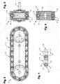
- FIG. 1 shows two pushers 2 in one embodiment of the invention. Viewed in the conveying direction, the pusher elements 2 have a single distancing body 4 in the center of the pusher element 2, and a respective roller 3, which is arranged rotatable about the axis 5, to the left and right of the distancing body 4.
- the Distanzianss stresses 4 are elongated and have thrust transfer surfaces 12, one of which are each formed as a segment of a spherical surface, wherein the ball center is located on the axis 5.
- the other thrust transfer surfaces 12 are located away from the axis 5 and formed as spherical shells with the same radius.
- this embodiment is not exclusively suitable for tracks whose axes of curvature are parallel and / or perpendicular to the axes 5.
- the rollers 3 may be mounted individually on the axle 5, or be attached to a common shaft which passes through the distancing body 4.
- the rollers 3 each have a flange, that is a section with a larger radius and with an oblique edge 17 for lateral guidance.
- the rollers 3 can be pushed around a curve similar to a railroad whose axis of curvature is perpendicular to the axes 5 of the pushers 2.
- a wheel flange on the rollers and the Distanzianss stresses 4 and / or the guide body 10 may have means for lateral guidance, such as grooves or protruding elements.
- the rollers may also have grooves and / or cambered for lateral guidance, i. be barrel-shaped.
- Figures 2-4 show different views and sections of a transmission with the pushers 2 of the FIG. 1 ,
- the conveyor device 1 thus does not work to convey other objects, but to promote the thrust elements 2 itself to a rotating conveyor track 7, and for transmitting power via the pushers 2.
- the drive / output function is also reversible.
- drive wheel 8 and output gear 18 have different radii.
- FIG. 2 shows a side view
- FIG. 3 a cross section in the region of a drive wheel 8 or output gear 18, and
- FIG. 4 a cross section in the intermediate area.
- a wall of the conveyor track 7 acts as a guide surface 13: If a gap arises between two pushers 2, the Distanzianss redesign 4 can only turn away so far until the free end, that is the end remote from the axis 5, on the guide surface 13 is present. When the gap is closed later, the thrust transfer surface 12 of the subsequent pusher element 2 pushes the distancing body 4 back into the middle position, as is normal in the pushing force transmission.
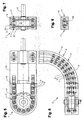
- FIG. 5 shows a side view of the transmission
- FIG. 6 a partial supervision
- FIG. 7 a cross section in the region of a deflection or driven wheel 18
- FIG. 8 a cross section in the intermediate area.
- such a transmission can be realized with pushing elements 2 pushing elements 2 without rollers 3, wherein the drive wheel 8 and output gear 18 engage the push elements themselves.
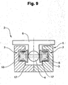
- FIG. 9 shows a part of a conveying device 1 with a pushing element 2 with a support member 6.
- the support member 6 is attached to the spacer body 4 or formed integrally therewith.
- the guide body 10 has a circumferential slot through which the carrier element 6 extends outwards.
- the conveyor track 7 is curved only about an axis perpendicular to the axes 5.
- the conveyor track 7 can also have any spatial curvatures in all directions and twists or torsions.
- the spacer body 4 have a cylindrical thrust transfer surface 12, whose cylinder axis is parallel to the axes of curvature, and the support elements 6 have first contact surfaces 14, which are also cylindrical with the cylinder axis parallel to the axes of curvature.
Landscapes
- Engineering & Computer Science (AREA)
- Mechanical Engineering (AREA)
- Rollers For Roller Conveyors For Transfer (AREA)
- Chain Conveyers (AREA)
- Electrical Discharge Machining, Electrochemical Machining, And Combined Machining (AREA)
- Die Bonding (AREA)
- Container, Conveyance, Adherence, Positioning, Of Wafer (AREA)
- Advancing Webs (AREA)
- Auxiliary Devices For And Details Of Packaging Control (AREA)
- Pusher Or Impeller Conveyors (AREA)
Description
- Die Erfindung bezieht sich auf das Gebiet der Fördertechnik und insbesondere auf eine Fördervorrichtung mit Schubelementen gemäss dem Oberbegriff des Patentanspruches 1.
- Bei bekannten Fördersystemen, welche Bänder oder Ketten von gleichartigen Elementen aufweisen, muss stets die Länge der Bänder oder Ketten an die Länge der Fördereinrichtung angepasst werden. Die Bänder oder Ketten müssen in die Fördereinrichtung eingefädelt werden und anschliessend zu einem umlaufenden Gebilde verbunden und gespannt werden. Bei bandähnlichen Fördereinrichtungen soll zudem eine möglichst ebene Oberfläche zur Aufnahme von zu fördernden Gegenständen gebildet werden. Ferner soll zum Bewegen der Einrichtung möglichst wenig Kraft aufzuwenden sein.
- In der
WO 2004/063059 A1 ist ein Fördersystem beschrieben, welches steife Lamellen mit dazwischen liegenden kompressiblen Elementen schiebend und ziehend fördert. Die kompressiblen Elemente sind in Förderrichtung vorgespannt, d.h. teilweise komprimiert, und können um Kurven geführt werden, ohne dass Lücken in der Förderfläche entstehen. Die Lamellen weisen seitlich hervorstehende Zähne auf, so dass sie durch korrespondierend geformte Zähne eines Antriebsmittels angetrieben werden können. - In der
FR 143 262 - In der
WO 2005/113 391 und derWO 2005/113392 werden keine Fördersysteme, sondern Wälzlager offenbart. In diesen liegen zur Aufnahme von hohen Lastkräften umlaufende Rollen vor. Diese Rollen laufen um einen ovalen Rollenkörper und sind durch mitlaufende Körper voneinander beabstandet. Die Rollen rollen wie bei einem üblichen Wälzlager einerseits auf dem Rollenkörper und andererseits an einem Gegenkörper ab, und nehmen so eine Lastkraft zwischen Rollenkörper und Gegenkörper auf. - Die
EP 0 488 296 A1 offenbart eine Fördereinrichtung, in welcher einzelne Trägerelemente, welche nicht aneinander gehängt sind, durch eine Führung geschoben werden. Die Trägerelemente weisen an den beiden Enden jeweils Rollen auf, mit welchen sie in einer Führung abrollen. Die Trägerelemente sind zylindrisch geformt oder bilden, in einer anderen Ausführungsform, wenn sie gegeneinander geschoben sind, eine einigermassen ebene Fläche. In der letztgenannten Ausführungsform sind die Trägerelemente durch Distanzelemente voneinander beabstandet. Wenn die Trägerelemente um eine Kurve gefördert werden, reiben die Distanzelemente aneinander und erschweren so die Förderung. - Keine der bekannten Fördervorrichtungen weist die gewünschten Eigenschaften auf.
- Es ist Aufgabe der Erfindung, eine Fördervorrichtung mit Schubelementen der eingangs genannten Art zu schaffen, welche eine Übertragung hoher Kräfte erlaubt, und einfach, ohne besondere Anpassungsarbeiten, montiert werden kann. Eine weitere Aufgabe der Erfindung ist, eine Fördervorrichtung zu schaffen, die eine ebene und hoch belastbare Lastfläche ohne Lücken aufweist. Eine weitere Ausführungsform der Erfindung ist, eine Fördervorrichtung zu schaffen, welche als Getriebe zur Übertragung hoher Kräfte um Kurven herum verwendbar ist.
- Diese Aufgabe löst eine Fördervorrichtung mit Schubelementen mit den Merkmalen des Patentanspruches 1.
- In der Fördervorrichtung mit Schubelementen weist jedes der Schubelemente jeweils mindestens ein Rollenelement und mindestens einen Distanzierungskörper auf, wobei der mindestens eine Distanzierungskörper zur Beabstandung von Schubelementen, welche in der Fördervorrichtung aufeinander folgen, ausgebildet ist. Dabei erstrecken sich aufeinanderfolgende Schubelemente in Förderrichtung von einem ersten Ende zu einem zweiten Ende, und sind die Schubelemente im Bereich des ersten Endes durch das mindestens eine Rollenelement gegenüber einer Förderbahn beweglich gelagert. Im Bereich des zweiten Endes sind die die Schubelemente jeweils an einem anschliessenden Schubelement abgestützt. Es sind aufeinander folgende Schubelemente bezüglich einander nur auf Druck aber nicht auf Zug belastbar.
- Die Schubelemente sind also nicht miteinander gekoppelt, und können nur Schubkräfte übertragen. Mit anderen Worten: die Schubelemente liegen lose gegeneinander und können sich, solange sie nicht gegeneinander gestossen werden, voneinander weg bewegen. Dies macht es möglich, die Schubelemente einzeln herzustellen und bereitzustellen. Beim Herstellen der Fördervorrichtung werden die Schubelemente einzeln in eine Förderbahn eingefüllt. Es ist nicht erforderlich, eine Länge eines Bandes oder einer Kette genau auf die Länge der Förderbahn abzustimmen. Es werden beispielsweise gerade so viele Schubelemente wie möglich eingefüllt. Dabei wird, wenn alle anderen Schubelemente gegeneinander geschoben sind, im Normalfall noch eine Lücke zwischen zwei Schubelementen verbleiben. Beim Antreiben der Folge von Schubelementen werden diese zusammengeschoben, und nur gerade vor einem Antrieb kann eine solche Lücke entstehen. Die Fördervorrichtung kann so ausgelegt werden, dass diese Lücke in einem Bereich liegt, wo sie nicht stört.
- Die Schubelemente weisen Rollenelemente auf, was die notwendige Kraft zum Antreiben einer Folge von Schubelementen verringert. Ein Schubelement ist nicht an beiden Enden durch beispielsweise Rollen, welche ja Teil des Schubelementes sind, direkt gegenüber der Förderbahn gelagert, sondern nur an einem Ende. Am anderen Ende ist das Schubelement indirekt über ein benachbartes (vorangehendes oder nachfolgendes) Schubelement gegenüber der Förderbahn gelagert. Dadurch, dass die Schubelemente nur an einem Ende gelagert sind, wobei die Schubelemente sich gegenseitig stützen, wird der Rollwiderstand im Vergleich zu mehrachsigen Ausführungen klein gehalten. Der Antrieb kann an den Rollenelementen und/oder an den Distanzierungskörpern und/oder an Trägerelementen der Schubelemente angreifen. Dazu sind diese in bevorzugten Ausführungsformen der Erfindung mit Nocken oder Mitnehmern ausgebildet.
- In einer bevorzugten Ausführungsform der Erfindung sind das oder die Rollenelemente bezüglich des mindestens einen Distanzierungskörpers um genau eine gemeinsame geometrische Achse drehbar. Das heisst also, dass zwei oder mehr Rollen, die am ersten Ende des Schubelementes gelagert sind, koaxial zueinander sind. Eine "gemeinsame geometrische Achse" bedeutet in anderen Worten, dass die Rollenelemente um dieselbe Drehachse im geometrischen Sinne drehbar sind. Diese Drehachse kann durch separate physische Achselemente, die miteinander fluchten gebildet sein, oder aber durch eine gemeinsame physische Achse oder eine gemeinsame Welle. Jedes der Schubelemente weist also nur eine Achse auf, um welche sich seine Rollenelemente drehen, und umgekehrt ist also auch das Schubelement um diese Achse bezüglich der Rollenelemente drehbar.
- In einer anderen bevorzugten Ausführungsform der Erfindung weisen die Rollenelemente mehr als eine geometrische Achse auf: Vorzugsweise sind jeweils zwei Rollen mit parallelen Achsen am ersten Ende eines Schubelementes angeordnet und sind in der Richtung senkrecht zu der Achsrichtung voneinander beabstandet. Die beiden Rollen drehen sich dabei vorzugsweise im wesentlichen in derselben Ebene. Die Rollen laufen in einer Förderbahn, welche die Schubelemente mit den Rollen umschliesst und am ersten Ende rollend abstützt. Auch hier sind die Schubelemente am zweiten Ende jeweils formschlüssig gegen ein erstes Ende eines benachbarten Schubelementes gestossen. Zwischen dem ersten und dem zweiten Ende weisen die Schubelemente Abstützbereiche auf, welche beim normalen Abrollen fast, aber nicht ganz bis zur Förderbahn reichen. Im Zustand, in welchem die Schubelemente voneinander weg bewegt sind, drehen sich die Schubelemente leicht ab, bis sie durch die Abstützbereiche gleitend an der Förderbahn abgestützt sind. Da die Schubelemente nur beschränkt weggedreht sind, werden sie beim erneuten Aneinanderstossen durch das jeweils benachbarte Schubelement wieder in die korrekte Lage geschoben.
- Dasselbe gilt für die Ausführungsformen mit nur einer geometrischen Achse der Rollen: Wenn zwischen zwei Schubelementen, die nicht gegeneinander gestossen werden eine Lücke entsteht, so wird sich das Schubelement aufgrund der Schwerkraft oder aufgrund anderer Kräfte um diese Achse drehen. Wenn die Schubelemente wieder gegeneinander gestossen werden, müssen die Schubelemente wieder in die korrekte gegenseitige Lage gelangen. Zu diesem Zweck weist die Förderbahn Führungsmittel zum losen Führen der Distanzierungskörper auf. Diese Führungsmittel verhindern, dass sich die Schubelemente oder auch nur die Distanzierungskörper zu weit aus der korrekten Position weg drehen.
- In einer bevorzugten Ausführungsform der Erfindung weisen die Distanzierungskörper Schubübertragungsflächen auf, welche als Segment einer Zylinderfläche oder Kugelfläche geformt sind, wobei die Zylinderachse mit der Achse zusammenfällt, respektive der Kugelmittelpunkt auf der Achse des jeweiligen Schubelementes liegt. Dies erlaubt, wenn sich die Schubelemente um eine Kurve der Förderbahn bewegen, eine gegenseitige Verdrehung der Distanzierungskörper ohne Änderung des Abstandes zwischen den Achsen der Schubelemente.
- In einer weiteren bevorzugten Ausführungsform der Erfindung weisen die Schubelemente jeweils ein Trägerelement zum Fördern von Gegenständen auf. Damit kann eine Fördervorrichtung zum Fördern von Gegenständen erstellt werden, wobei die Gegenstände beispielsweise auf eine flache Oberfläche der Trägerelemente gelegt werden.
- In einer weiteren bevorzugten Ausführungsform der Erfindung sind die Trägerelemente von aufeinanderfolgenden Schubelementen korrespondierend zueinander geformt und bewegen sich beim Bewegen der Schubelemente um eine Kurve die Trägerelemente gleitend zueinander, wobei Lastflächen der Trägerelemente gemeinsam eine Oberfläche zum Fördern von Gegenständen bilden. Eine solche Förderfläche ist ähnlich einem Förderband, aber mit viel höherer Belastbarkeit, ohne Durchhängen und ohne dass Stützrollen durch das Band spürbar werden.
- In anderen bevorzugten Ausführungsformen der Erfindung weisen die Trägerelemente Mittel zum zeitweisen Festhalten von Gegenständen auf, beispielsweise Greifer.
- In einer weiteren bevorzugten Ausführungsform der Erfindung werden die Schubelemente durch ein Antriebsrad angetrieben und treiben selber wiederum ein Abtriebsrad an. Zwischen diesen Rädern kann eine Förderbahn der Schubelemente einen im wesentlichen beliebigen Verlauf aufweisen. Es kann so also ein Getriebe zur Übertragung hoher Kräfte mit einer freien Wahl der Lage der Achsen von Antrieb und Abtrieb realisiert werden.
- Weitere bevorzugte Ausführungsformen gehen aus den abhängigen Patentansprüchen hervor.
- Im folgenden wird der Erfindungsgegenstand anhand von bevorzugten Ausführungsbeispielen, welche in den beiliegenden Zeichnungen dargestellt sind, näher erläutert. Es zeigen jeweils schematisch:
- Figur 1
- zwei Schubelemente in einer Ausführungsform der Erfindung;
- Figur 2-4
- verschiedene Ansichten und Schnitte eines Getriebes mit den Schubelementen der
Figur 1 ; - Figur 5-8
- verschiedene Ansichten und Schnitte eines weiteren Getriebes; und
- Figur 9
- einen Teil einer Fördervorrichtung mit einem Schubelement mit einem Trägerelement.
- Die in den Zeichnungen verwendeten Bezugszeichen und deren Bedeutung sind in der Bezugszeichenliste zusammengefasst aufgelistet. Grundsätzlich sind in den Figuren gleiche Teile mit gleichen Bezugszeichen versehen.
-
Figur 1 zeigt zwei Schubelemente 2 in einer Ausführungsform der Erfindung. Die Schubelemente 2 weisen in Förderrichtung betrachtet einen einzelnen Distanzierungskörper 4 in der Mitte des Schubelementes 2 auf, und links und rechts des Distanzierungskörpers 4 je eine Rolle 3, welche um die Achse 5 drehbar angeordnet ist. - Die Distanzierungskörper 4 sind länglich und weisen Schubübertragungsflächen 12 auf, von denen die einen jeweils als Segment einer Kugelfläche geformt sind, wobei der Kugelmittelpunkt auf der Achse 5 liegt. Die anderen Schubübertragungsflächen 12 sind von der Achse 5 entfernt angeordnet und als Kugelschalen mit gleichem Radius ausgebildet. Diese Ausführungsform ist dadurch vor allem aber nicht ausschliesslich für Bahnen geeignet, deren Krümmungsachsen parallel und/oder senkrecht zu den Achsen 5 verlaufen.
- Die Rollen 3 können einzeln auf der Achse 5 gelagert sein, oder an einer gemeinsamen Welle, welche durch den Distanzierungskörper 4 führt, befestigt sein. In einer bevorzugten Ausführungsform der Erfindung weisen die Rollen 3 jeweils einen Spurkranz auf, also einen Abschnitt mit grösserem Radius und mit einer schrägen Flanke 17 zur seitlichen Führung. Damit können die Rollen 3 ähnlich wie bei einer Eisenbahn um eine Kurve geschoben werden, deren Krümmungsachse senkrecht zu den Achsen 5 der Schubelemente 2 verläuft. Anstelle eines Spurkranzes an den Rollen können auch die Distanzierungskörper 4 und/oder die Führungskörper 10 Mittel zur seitlichen Führung aufweisen, beispielsweise Nuten oder hervorstehende Elemente. Die Rollen können zur seitlichen Führung ebenfalls Nuten aufweisen und/oder bombiert, d.h. fassähnlich geformt sein.
-
Figuren 2-4 zeigen verschiedene Ansichten und Schnitte eines Getriebes mit den Schubelementen 2 derFigur 1 . Hier wirkt die Fördervorrichtung 1 also nicht zum Fördern von weiteren Gegenständen, sondern zum Fördern der Schubelemente 2 selber um eine umlaufende Förderbahn 7, und zur Kraftübertragung über die Schubelemente 2. Dabei wird eines der Umlenkräder als Antriebsrad 8 und das andere als Abtriebsrad 18 verwendet. Die Funktion Antrieb/Abtrieb ist aber auch umkehrbar. In einer anderen Ausführungsform der Erfindung weisen Antriebsrad 8 und Abtriebsrad 18 unterschiedliche Radien auf. -
Figur 2 zeigt eine Seitenansicht,Figur 3 einen Querschnitt im Bereich eines Antriebsrades 8 oder Abtriebsrades 18, undFigur 4 einen Querschnitt im dazwischen liegenden Bereich. InFigur 4 ist ersichtlich, wie eine Wand der Förderbahn 7 als Führungsfläche 13 wirkt: Falls zwischen zwei Schubelementen 2 eine Lücke entsteht, kann sich der Distanzierungskörper 4 nur soweit wegdrehen, bis das freie Ende, das heisst das von der Achse 5 entfernte Ende, an der Führungsfläche 13 anliegt. Wenn später die Lücke geschlossen wird, drückt die Schubübertragungsfläche 12 des nachfolgenden Schubelementes 2 den Distanzierungskörper 4 wieder in die mittlere Lage, wie sie bei der stossenden Kraftübertragung normal ist. -
Figuren 5-8 zeigen verschiedene Ansichten und Schnitte eines weiteren Getriebes. Das Wirkprinzip ist dasselbe wie bei der Ausführungsform gemäss denFiguren 2 - 4 , jedoch ist hier eine Führung um zwei verschiedene Krümmungsachsen illustriert. Die Achsen von Antriebsrad 8 und Abtriebsrad 18 sind also nicht parallel zueinander.Figur 5 zeigt eine Seitenansicht des Getriebes,Figur 6 eine teilweise Aufsicht,Figur 7 einen Querschnitt im Bereich eines Umlenk-oder Abtriebsrades 18, undFigur 8 einen Querschnitt im dazwischen liegenden Bereich. Im Prinzip kann ein solches Getriebe mit stossenden Schubelementen 2 auch mit Schubelementen 2 ohne Rollen 3 realisiert werden, wobei Antriebsrad 8 und Abtriebsrad 18 an den Schubelementen selber angreifen. -
Figur 9 zeigt einen Teil einer Fördervorrichtung 1 mit einem Schubelement 2 mit einem Trägerelement 6. Das Trägerelement 6 ist am Distanzierungskörper 4 befestigt oder mit diesem einstückig ausgebildet. Der Führungskörper 10 weist einen umlaufenden Schlitz auf, durch welchen sich das Trägerelement 6 nach aussen erstreckt. In einer bevorzugten Ausführungsform der Erfindung ist die Förderbahn 7 nur um eine Achse senkrecht zu den Achsen 5 gekrümmt. Die Förderbahn 7 kann grundsätzlich auch beliebige räumliche Krümmungen in alle Richtungen und Verdrehungen respektive Tordierungen aufweisen. Die Distanzierungskörper 4 weisen eine zylindrische Schubübertragungsfläche 12 auf, deren Zylinderachse parallel zu den Krümmungsachsen verläuft, und die Trägerelemente 6 weisen erste Kontaktflächen 14 auf, die ebenfalls zylindrisch mit der Zylinderachse parallel zu den Krümmungsachsen sind. -
- 1
- Fördervorrichtung
- 2
- Schubelement
- 3
- Rolle
- 4
- Distanzierungskörper
- 5
- Achse
- 6
- Trägerelement
- 7
- Förderbahn
- 8
- Antriebsrad
- 9
- Ausnehmung
- 10
- Führungskörper
- 11
- Antriebswelle
- 12
- Schubübertragungsfläche
- 13
- Führungsfläche
- 14
- erste Kontaktfläche
- 15
- zweite Kontaktfläche
- 16
- Lastfläche
- 17
- Flanke
- 18
- Abtriebsrad
Claims (6)
- Fördervorrichtung (1) zum Fördern von einzelnen Schubelementen (2), dadurch gekennzeichnet, dass jedes der Schubelemente (2) jeweils mindestens ein Rollenelement (3) und mindestens einen Distanzierungskörper (4) aufweist, wobei der mindestens eine Distanzierungskörper (4) zur Beabstandung von Schubelementen (2), welche in der Fördervorrichtung (1) aufeinander folgen, ausgebildet ist, und wobei sich aufeinanderfolgende Schubelemente (2) in Förderrichtung von einem ersten Ende zu einem zweiten Ende erstrecken, und die Schubelemente (2) im Bereich des ersten Endes durch das mindestens eine Rollenelement (3) gegenüber einer Förderbahn (7) beweglich gelagert sind, und die Schubelemente (2) im Bereich des zweiten Endes an einem anschliessenden Schubelement (2) abgestützt sind, und dass aufeinander folgende Schubelemente (2) bezüglich einander nur auf Druck aber nicht auf Zug belastbar sind, dadurch gekennzeichnet, dass in Förderrichtung betrachtet ein Distanzierungskörper (4) in der Mitte des Schubelementes (2) angeordnet ist und links und rechts des Distanzierungskörpers (4) je eine Rolle (3) um eine Achse (5) drehbar angeordnet ist, wobei jedes der Schubelemente nur eine solche Achse (5) mit Rollen (3) aufweist.
- Fördervorrichtung (1) gemäss Anspruch 1, dadurch gekennzeichnet, dass die Schubübertragungsflächen (12) des Distanzierungskörpers (4) auf der einen Seite als Kugelflächen und auf der anderen Seite als Kugelschalen ausgebildet sind, und der Mittelpunkt der Kugelflächen jeweils auf der Achse (5) liegt.
- Fördervorrichtung (1) gemäss Anspruch 1 oder 2, dadurch gekennzeichnet, dass die Rollen (3) jeweils einen Abschnitt mit einer schrägen Flanke (17) zur seitlichen Führung aufweisen.
- Fördervorrichtung (1) gemäss einem der Ansprüche 1 bis 3, dadurch gekennzeichnet, dass die Fördervorrichtung (1) als Getriebe zum Übertragen von Kraft von einem Antriebsmittel (8) auf ein Abtriebsmittel (18) ausgebildet ist, wobei ein Satz von Schubelementen (2) durch die Fördervorrichtung (1) um eine umlaufende Förderbahn (7) geführt ist und die Schubelemente (2) dabei zeitweise mit dem Antriebsmittel (8) und dem Abtriebsmittel (18) im Eingriff sind.
- Fördervorrichtung (1) gemäss einem der Ansprüche 1 bis 4, dadurch gekennzeichnet, dass die Förderbahn (7) Führungsmittel (13) zum losen Führen der Distanzierungskörper (4) aufweist, so dass bei Schubelementen (2), die sich voneinander wegbewegt haben, beim erneuten gegeneinander Bewegen die Distanzierungskörper (4) in die korrekte Position zur Schubübertragung gelangen, und in dieser Position aufeinander abgestützt sind.
- Schubelement (2), zur Verwendung in der Fördervorrichtung (1) gemäss einem der bisherigen Ansprüche.
Priority Applications (4)
| Application Number | Priority Date | Filing Date | Title |
|---|---|---|---|
| DK09008958.2T DK2110344T3 (da) | 2006-01-13 | 2007-01-08 | Transportindretning med skubbeelement |
| PL09008958T PL2110344T3 (pl) | 2006-01-13 | 2007-01-08 | Urządzenie transportowe z elementem przesuwającym |
| PL07700107T PL1973818T3 (pl) | 2006-01-13 | 2007-01-08 | Urządzenie transportowe z elementem pchanym |
| EP09008958A EP2110344B1 (de) | 2006-01-13 | 2007-01-08 | Fördervorrichtung mit Schubelement |
Applications Claiming Priority (2)
| Application Number | Priority Date | Filing Date | Title |
|---|---|---|---|
| CH562006 | 2006-01-13 | ||
| PCT/CH2007/000009 WO2007079603A1 (de) | 2006-01-13 | 2007-01-08 | Fördervorrichtung mit schubelement |
Related Child Applications (2)
| Application Number | Title | Priority Date | Filing Date |
|---|---|---|---|
| EP09008958A Division EP2110344B1 (de) | 2006-01-13 | 2007-01-08 | Fördervorrichtung mit Schubelement |
| EP09008958.2 Division-Into | 2009-07-09 |
Publications (2)
| Publication Number | Publication Date |
|---|---|
| EP1973818A1 EP1973818A1 (de) | 2008-10-01 |
| EP1973818B1 true EP1973818B1 (de) | 2010-05-19 |
Family
ID=36072243
Family Applications (2)
| Application Number | Title | Priority Date | Filing Date |
|---|---|---|---|
| EP07700107A Not-in-force EP1973818B1 (de) | 2006-01-13 | 2007-01-08 | Fördervorrichtung mit schubelement |
| EP09008958A Not-in-force EP2110344B1 (de) | 2006-01-13 | 2007-01-08 | Fördervorrichtung mit Schubelement |
Family Applications After (1)
| Application Number | Title | Priority Date | Filing Date |
|---|---|---|---|
| EP09008958A Not-in-force EP2110344B1 (de) | 2006-01-13 | 2007-01-08 | Fördervorrichtung mit Schubelement |
Country Status (11)
| Country | Link |
|---|---|
| US (1) | US7857124B2 (de) |
| EP (2) | EP1973818B1 (de) |
| JP (2) | JP5256046B2 (de) |
| AT (1) | ATE468289T1 (de) |
| AU (1) | AU2007204545B2 (de) |
| CA (1) | CA2636385A1 (de) |
| DE (1) | DE502007003842D1 (de) |
| DK (2) | DK2110344T3 (de) |
| ES (2) | ES2392620T3 (de) |
| PL (2) | PL1973818T3 (de) |
| WO (1) | WO2007079603A1 (de) |
Families Citing this family (3)
| Publication number | Priority date | Publication date | Assignee | Title |
|---|---|---|---|---|
| US7987973B2 (en) | 2008-08-18 | 2011-08-02 | Ammeraal Beltech Modular A/S | Pushing belt |
| US10752446B2 (en) * | 2015-09-25 | 2020-08-25 | Habasit Ag | Hybrid modular belt |
| CN108725830A (zh) * | 2017-04-17 | 2018-11-02 | 攸县天帆电池制造有限公司 | 前上偏心力前平衡梁挂钩拖动机航母电磁飞轮蓄能弹射器 |
Family Cites Families (15)
| Publication number | Priority date | Publication date | Assignee | Title |
|---|---|---|---|---|
| US3102153A (en) * | 1958-05-02 | 1963-08-27 | Metallgesellschaft Ag | Sintering apparatus |
| JPS58144007A (ja) * | 1982-02-23 | 1983-08-27 | Imai Tekkosho:Kk | ブロツク搬送装置 |
| JPH0242652Y2 (de) * | 1985-04-03 | 1990-11-14 | ||
| US5064054A (en) * | 1989-05-25 | 1991-11-12 | Hoppmann Corporation | Overlapping flat surface transport carrier conveyor |
| JPH0624227U (ja) * | 1991-11-20 | 1994-03-29 | 東洋製罐株式会社 | ウイケット移送用ローラ |
| DE19701579B4 (de) | 1996-12-13 | 2006-10-26 | Dbt Gmbh | Gliederkette für Kettenförderer, insbesondere Kettenkratzförderer für den Bergbaueinsatz |
| US5791455A (en) * | 1996-12-16 | 1998-08-11 | Tekno, Inc. | High tension conveyor chain with rollers |
| IT249695Y1 (it) * | 2000-01-13 | 2003-05-28 | Fata Automation | Impianto di trasporto con trasportatore dotato di rulli folli di appoggio di elementi di trasporto |
| DE20205069U1 (de) * | 2002-03-30 | 2003-05-08 | KRONES AG, 93073 Neutraubling | Transportvorrichtung für Stückgüter |
| NL1022344C2 (nl) | 2003-01-10 | 2004-07-26 | Marinus Tieme Ilmer | Inrichting voor het verplaatsen van objecten over zowel een recht als een gebogen traject. |
| US6896122B2 (en) * | 2003-06-20 | 2005-05-24 | Rapistan Systems Advertising Corp. | Chain conveyor and clip |
| JP2005206327A (ja) * | 2004-01-23 | 2005-08-04 | Fuji Electric Systems Co Ltd | モールドコンベヤ |
| EP1758801B1 (de) | 2004-05-21 | 2009-12-02 | WRH Walter Reist Holding AG | Rollenelement |
| CH703149B1 (de) | 2004-05-21 | 2011-11-30 | Wrh Walter Reist Holding Ag | Rollenantriebselement. |
| US7523820B1 (en) * | 2008-02-22 | 2009-04-28 | Precision Motion Industries, Inc. | Rolling element chain |
-
2007
- 2007-01-08 JP JP2008549737A patent/JP5256046B2/ja not_active Expired - Fee Related
- 2007-01-08 AU AU2007204545A patent/AU2007204545B2/en not_active Ceased
- 2007-01-08 CA CA002636385A patent/CA2636385A1/en not_active Abandoned
- 2007-01-08 DK DK09008958.2T patent/DK2110344T3/da active
- 2007-01-08 WO PCT/CH2007/000009 patent/WO2007079603A1/de not_active Ceased
- 2007-01-08 DE DE502007003842T patent/DE502007003842D1/de active Active
- 2007-01-08 US US12/160,697 patent/US7857124B2/en not_active Expired - Fee Related
- 2007-01-08 DK DK07700107.1T patent/DK1973818T3/da active
- 2007-01-08 ES ES09008958T patent/ES2392620T3/es active Active
- 2007-01-08 EP EP07700107A patent/EP1973818B1/de not_active Not-in-force
- 2007-01-08 PL PL07700107T patent/PL1973818T3/pl unknown
- 2007-01-08 AT AT07700107T patent/ATE468289T1/de active
- 2007-01-08 EP EP09008958A patent/EP2110344B1/de not_active Not-in-force
- 2007-01-08 PL PL09008958T patent/PL2110344T3/pl unknown
- 2007-01-08 ES ES07700107T patent/ES2346582T3/es active Active
-
2010
- 2010-01-05 JP JP2010000707A patent/JP5238728B2/ja not_active Expired - Fee Related
Also Published As
| Publication number | Publication date |
|---|---|
| JP5238728B2 (ja) | 2013-07-17 |
| EP1973818A1 (de) | 2008-10-01 |
| JP5256046B2 (ja) | 2013-08-07 |
| ES2346582T3 (es) | 2010-10-18 |
| PL1973818T3 (pl) | 2011-01-31 |
| PL2110344T3 (pl) | 2013-01-31 |
| US7857124B2 (en) | 2010-12-28 |
| CA2636385A1 (en) | 2007-07-19 |
| ATE468289T1 (de) | 2010-06-15 |
| JP2010100434A (ja) | 2010-05-06 |
| EP2110344B1 (de) | 2012-08-01 |
| JP2009523111A (ja) | 2009-06-18 |
| US20100163371A1 (en) | 2010-07-01 |
| WO2007079603A1 (de) | 2007-07-19 |
| DK2110344T3 (da) | 2012-11-05 |
| DK1973818T3 (da) | 2010-09-06 |
| ES2392620T3 (es) | 2012-12-12 |
| AU2007204545B2 (en) | 2012-03-08 |
| DE502007003842D1 (de) | 2010-07-01 |
| AU2007204545A1 (en) | 2007-07-19 |
| EP2110344A1 (de) | 2009-10-21 |
Similar Documents
| Publication | Publication Date | Title |
|---|---|---|
| EP2289822B1 (de) | Stützvorrichtung zum Fördern schwerer Lasten | |
| EP2289823B1 (de) | Stützvorrichtung für eine Fördereinrichtung und Verfahren zum Betrieb einer Fördereinrichtung | |
| EP2163494B1 (de) | Rollenelement | |
| EP2117971B1 (de) | Fördersystem | |
| DE2100240C3 (de) | Mehrfachgutförderer, insbesondere für den Transport von Personen, mit sich ändernder Fördergeschwindigkeit | |
| DE2636160A1 (de) | Endlosfoerderer | |
| CH703149B1 (de) | Rollenantriebselement. | |
| EP2766620B1 (de) | Teleskopierendes führungssystem | |
| DE69120051T2 (de) | Hochgeschwindigkeitsrollenbau | |
| EP2314529B1 (de) | Transporteinheit mit Stauröllchenketten | |
| EP1412265B1 (de) | Staufähiges kurvenelement für ein transfersystem | |
| EP1375390A2 (de) | Vorrichtung zur Förderung von Stückgütern | |
| EP2613996A1 (de) | Vorrichtung zum fördern von fahrzeugkarosserien | |
| EP1973818B1 (de) | Fördervorrichtung mit schubelement | |
| EP2210832A1 (de) | Fördervorrichtung und Rollkörper | |
| DE2729091A1 (de) | Schlupfgesteuerter, drehmomentbegrenzter transmissionsantrieb | |
| EP2212221B1 (de) | Antrieb von fördermitteln oder geförderten gegenständen | |
| EP3689796B1 (de) | Laufrollen mit vorspannung bei mechanischer kurvenführung | |
| EP1858782A1 (de) | Fördervorrichtung, rollenkörper und förderkörper | |
| EP2754626A1 (de) | Fördervorrichtung mit konkavem Gurt | |
| DE4300271A1 (de) | Kurvengängiger Kurzbandförderer | |
| DE202019005294U1 (de) | Rollenförderer und neuartige Antriebsscheibeneinheit | |
| DE3805870A1 (de) | Foerdervorrichtung fuer spreizanlagen und dergl. | |
| EP0492096A1 (de) | Förderbahn zum staudruckfreien Transport runder oder rundähnlicher Teile |
Legal Events
| Date | Code | Title | Description |
|---|---|---|---|
| PUAI | Public reference made under article 153(3) epc to a published international application that has entered the european phase |
Free format text: ORIGINAL CODE: 0009012 |
|
| 17P | Request for examination filed |
Effective date: 20080711 |
|
| AK | Designated contracting states |
Kind code of ref document: A1 Designated state(s): AT BE BG CH CY CZ DE DK EE ES FI FR GB GR HU IE IS IT LI LT LU LV MC NL PL PT RO SE SI SK TR |
|
| 17Q | First examination report despatched |
Effective date: 20081210 |
|
| GRAP | Despatch of communication of intention to grant a patent |
Free format text: ORIGINAL CODE: EPIDOSNIGR1 |
|
| RIN1 | Information on inventor provided before grant (corrected) |
Inventor name: REIST, WALTER |
|
| GRAS | Grant fee paid |
Free format text: ORIGINAL CODE: EPIDOSNIGR3 |
|
| GRAA | (expected) grant |
Free format text: ORIGINAL CODE: 0009210 |
|
| AK | Designated contracting states |
Kind code of ref document: B1 Designated state(s): AT BE BG CH CY CZ DE DK EE ES FI FR GB GR HU IE IS IT LI LT LU LV MC NL PL PT RO SE SI SK TR |
|
| REG | Reference to a national code |
Ref country code: GB Ref legal event code: FG4D Free format text: NOT ENGLISH |
|
| REG | Reference to a national code |
Ref country code: CH Ref legal event code: EP |
|
| REG | Reference to a national code |
Ref country code: IE Ref legal event code: FG4D Free format text: LANGUAGE OF EP DOCUMENT: GERMAN |
|
| REF | Corresponds to: |
Ref document number: 502007003842 Country of ref document: DE Date of ref document: 20100701 Kind code of ref document: P |
|
| REG | Reference to a national code |
Ref country code: CH Ref legal event code: NV Representative=s name: FREI PATENTANWALTSBUERO AG |
|
| REG | Reference to a national code |
Ref country code: NL Ref legal event code: T3 |
|
| REG | Reference to a national code |
Ref country code: DK Ref legal event code: T3 |
|
| REG | Reference to a national code |
Ref country code: SE Ref legal event code: TRGR |
|
| REG | Reference to a national code |
Ref country code: ES Ref legal event code: FG2A Ref document number: 2346582 Country of ref document: ES Kind code of ref document: T3 |
|
| LTIE | Lt: invalidation of european patent or patent extension |
Effective date: 20100519 |
|
| PG25 | Lapsed in a contracting state [announced via postgrant information from national office to epo] |
Ref country code: LT Free format text: LAPSE BECAUSE OF FAILURE TO SUBMIT A TRANSLATION OF THE DESCRIPTION OR TO PAY THE FEE WITHIN THE PRESCRIBED TIME-LIMIT Effective date: 20100519 |
|
| REG | Reference to a national code |
Ref country code: SK Ref legal event code: T3 Ref document number: E 7783 Country of ref document: SK |
|
| PG25 | Lapsed in a contracting state [announced via postgrant information from national office to epo] |
Ref country code: IS Free format text: LAPSE BECAUSE OF FAILURE TO SUBMIT A TRANSLATION OF THE DESCRIPTION OR TO PAY THE FEE WITHIN THE PRESCRIBED TIME-LIMIT Effective date: 20100919 Ref country code: LV Free format text: LAPSE BECAUSE OF FAILURE TO SUBMIT A TRANSLATION OF THE DESCRIPTION OR TO PAY THE FEE WITHIN THE PRESCRIBED TIME-LIMIT Effective date: 20100519 Ref country code: SI Free format text: LAPSE BECAUSE OF FAILURE TO SUBMIT A TRANSLATION OF THE DESCRIPTION OR TO PAY THE FEE WITHIN THE PRESCRIBED TIME-LIMIT Effective date: 20100519 |
|
| PG25 | Lapsed in a contracting state [announced via postgrant information from national office to epo] |
Ref country code: CY Free format text: LAPSE BECAUSE OF FAILURE TO SUBMIT A TRANSLATION OF THE DESCRIPTION OR TO PAY THE FEE WITHIN THE PRESCRIBED TIME-LIMIT Effective date: 20100602 |
|
| PG25 | Lapsed in a contracting state [announced via postgrant information from national office to epo] |
Ref country code: EE Free format text: LAPSE BECAUSE OF FAILURE TO SUBMIT A TRANSLATION OF THE DESCRIPTION OR TO PAY THE FEE WITHIN THE PRESCRIBED TIME-LIMIT Effective date: 20100519 Ref country code: PT Free format text: LAPSE BECAUSE OF FAILURE TO SUBMIT A TRANSLATION OF THE DESCRIPTION OR TO PAY THE FEE WITHIN THE PRESCRIBED TIME-LIMIT Effective date: 20100920 |
|
| REG | Reference to a national code |
Ref country code: PL Ref legal event code: T3 |
|
| PG25 | Lapsed in a contracting state [announced via postgrant information from national office to epo] |
Ref country code: RO Free format text: LAPSE BECAUSE OF FAILURE TO SUBMIT A TRANSLATION OF THE DESCRIPTION OR TO PAY THE FEE WITHIN THE PRESCRIBED TIME-LIMIT Effective date: 20100519 |
|
| PLBE | No opposition filed within time limit |
Free format text: ORIGINAL CODE: 0009261 |
|
| STAA | Information on the status of an ep patent application or granted ep patent |
Free format text: STATUS: NO OPPOSITION FILED WITHIN TIME LIMIT |
|
| 26N | No opposition filed |
Effective date: 20110222 |
|
| PG25 | Lapsed in a contracting state [announced via postgrant information from national office to epo] |
Ref country code: GR Free format text: LAPSE BECAUSE OF FAILURE TO SUBMIT A TRANSLATION OF THE DESCRIPTION OR TO PAY THE FEE WITHIN THE PRESCRIBED TIME-LIMIT Effective date: 20100820 |
|
| REG | Reference to a national code |
Ref country code: DE Ref legal event code: R097 Ref document number: 502007003842 Country of ref document: DE Effective date: 20110221 |
|
| PG25 | Lapsed in a contracting state [announced via postgrant information from national office to epo] |
Ref country code: MC Free format text: LAPSE BECAUSE OF NON-PAYMENT OF DUE FEES Effective date: 20110131 |
|
| PGFP | Annual fee paid to national office [announced via postgrant information from national office to epo] |
Ref country code: DK Payment date: 20130121 Year of fee payment: 7 Ref country code: CZ Payment date: 20121231 Year of fee payment: 7 Ref country code: FI Payment date: 20130111 Year of fee payment: 7 Ref country code: IE Payment date: 20130122 Year of fee payment: 7 Ref country code: SE Payment date: 20130122 Year of fee payment: 7 |
|
| PG25 | Lapsed in a contracting state [announced via postgrant information from national office to epo] |
Ref country code: LU Free format text: LAPSE BECAUSE OF NON-PAYMENT OF DUE FEES Effective date: 20110108 |
|
| PGFP | Annual fee paid to national office [announced via postgrant information from national office to epo] |
Ref country code: SK Payment date: 20130107 Year of fee payment: 7 Ref country code: BE Payment date: 20130128 Year of fee payment: 7 Ref country code: PL Payment date: 20130104 Year of fee payment: 7 |
|
| PG25 | Lapsed in a contracting state [announced via postgrant information from national office to epo] |
Ref country code: BG Free format text: LAPSE BECAUSE OF FAILURE TO SUBMIT A TRANSLATION OF THE DESCRIPTION OR TO PAY THE FEE WITHIN THE PRESCRIBED TIME-LIMIT Effective date: 20100819 Ref country code: TR Free format text: LAPSE BECAUSE OF FAILURE TO SUBMIT A TRANSLATION OF THE DESCRIPTION OR TO PAY THE FEE WITHIN THE PRESCRIBED TIME-LIMIT Effective date: 20100519 |
|
| PG25 | Lapsed in a contracting state [announced via postgrant information from national office to epo] |
Ref country code: HU Free format text: LAPSE BECAUSE OF FAILURE TO SUBMIT A TRANSLATION OF THE DESCRIPTION OR TO PAY THE FEE WITHIN THE PRESCRIBED TIME-LIMIT Effective date: 20100519 |
|
| PGFP | Annual fee paid to national office [announced via postgrant information from national office to epo] |
Ref country code: FR Payment date: 20140123 Year of fee payment: 8 |
|
| PGFP | Annual fee paid to national office [announced via postgrant information from national office to epo] |
Ref country code: GB Payment date: 20140121 Year of fee payment: 8 |
|
| BERE | Be: lapsed |
Owner name: WRH WALTER REIST HOLDING A.G. Effective date: 20140131 |
|
| PG25 | Lapsed in a contracting state [announced via postgrant information from national office to epo] |
Ref country code: CZ Free format text: LAPSE BECAUSE OF NON-PAYMENT OF DUE FEES Effective date: 20140108 |
|
| REG | Reference to a national code |
Ref country code: DK Ref legal event code: EBP Effective date: 20140131 |
|
| REG | Reference to a national code |
Ref country code: SE Ref legal event code: EUG |
|
| REG | Reference to a national code |
Ref country code: SK Ref legal event code: MM4A Ref document number: E 7783 Country of ref document: SK Effective date: 20140108 |
|
| PG25 | Lapsed in a contracting state [announced via postgrant information from national office to epo] |
Ref country code: FI Free format text: LAPSE BECAUSE OF NON-PAYMENT OF DUE FEES Effective date: 20140108 |
|
| REG | Reference to a national code |
Ref country code: IE Ref legal event code: MM4A |
|
| PG25 | Lapsed in a contracting state [announced via postgrant information from national office to epo] |
Ref country code: SE Free format text: LAPSE BECAUSE OF NON-PAYMENT OF DUE FEES Effective date: 20140109 Ref country code: SK Free format text: LAPSE BECAUSE OF NON-PAYMENT OF DUE FEES Effective date: 20140108 |
|
| PG25 | Lapsed in a contracting state [announced via postgrant information from national office to epo] |
Ref country code: DK Free format text: LAPSE BECAUSE OF NON-PAYMENT OF DUE FEES Effective date: 20140131 Ref country code: BE Free format text: LAPSE BECAUSE OF NON-PAYMENT OF DUE FEES Effective date: 20140131 Ref country code: IE Free format text: LAPSE BECAUSE OF NON-PAYMENT OF DUE FEES Effective date: 20140108 |
|
| REG | Reference to a national code |
Ref country code: PL Ref legal event code: LAPE |
|
| PG25 | Lapsed in a contracting state [announced via postgrant information from national office to epo] |
Ref country code: PL Free format text: LAPSE BECAUSE OF NON-PAYMENT OF DUE FEES Effective date: 20140108 |
|
| GBPC | Gb: european patent ceased through non-payment of renewal fee |
Effective date: 20150108 |
|
| PG25 | Lapsed in a contracting state [announced via postgrant information from national office to epo] |
Ref country code: GB Free format text: LAPSE BECAUSE OF NON-PAYMENT OF DUE FEES Effective date: 20150108 |
|
| REG | Reference to a national code |
Ref country code: FR Ref legal event code: ST Effective date: 20150930 |
|
| PG25 | Lapsed in a contracting state [announced via postgrant information from national office to epo] |
Ref country code: FR Free format text: LAPSE BECAUSE OF NON-PAYMENT OF DUE FEES Effective date: 20150202 |
|
| PGFP | Annual fee paid to national office [announced via postgrant information from national office to epo] |
Ref country code: CH Payment date: 20151215 Year of fee payment: 10 |
|
| PGFP | Annual fee paid to national office [announced via postgrant information from national office to epo] |
Ref country code: NL Payment date: 20160120 Year of fee payment: 10 |
|
| PGFP | Annual fee paid to national office [announced via postgrant information from national office to epo] |
Ref country code: ES Payment date: 20160112 Year of fee payment: 10 Ref country code: IT Payment date: 20160127 Year of fee payment: 10 Ref country code: DE Payment date: 20160120 Year of fee payment: 10 |
|
| PGFP | Annual fee paid to national office [announced via postgrant information from national office to epo] |
Ref country code: AT Payment date: 20160121 Year of fee payment: 10 |
|
| REG | Reference to a national code |
Ref country code: DE Ref legal event code: R119 Ref document number: 502007003842 Country of ref document: DE |
|
| REG | Reference to a national code |
Ref country code: CH Ref legal event code: PL |
|
| REG | Reference to a national code |
Ref country code: NL Ref legal event code: MM Effective date: 20170201 |
|
| REG | Reference to a national code |
Ref country code: AT Ref legal event code: MM01 Ref document number: 468289 Country of ref document: AT Kind code of ref document: T Effective date: 20170108 |
|
| PG25 | Lapsed in a contracting state [announced via postgrant information from national office to epo] |
Ref country code: CH Free format text: LAPSE BECAUSE OF NON-PAYMENT OF DUE FEES Effective date: 20170131 Ref country code: AT Free format text: LAPSE BECAUSE OF NON-PAYMENT OF DUE FEES Effective date: 20170108 Ref country code: LI Free format text: LAPSE BECAUSE OF NON-PAYMENT OF DUE FEES Effective date: 20170131 |
|
| PG25 | Lapsed in a contracting state [announced via postgrant information from national office to epo] |
Ref country code: DE Free format text: LAPSE BECAUSE OF NON-PAYMENT OF DUE FEES Effective date: 20170801 Ref country code: NL Free format text: LAPSE BECAUSE OF NON-PAYMENT OF DUE FEES Effective date: 20170201 |
|
| PG25 | Lapsed in a contracting state [announced via postgrant information from national office to epo] |
Ref country code: IT Free format text: LAPSE BECAUSE OF NON-PAYMENT OF DUE FEES Effective date: 20170108 |
|
| PG25 | Lapsed in a contracting state [announced via postgrant information from national office to epo] |
Ref country code: ES Free format text: LAPSE BECAUSE OF NON-PAYMENT OF DUE FEES Effective date: 20170109 |
|
| REG | Reference to a national code |
Ref country code: ES Ref legal event code: FD2A Effective date: 20181119 |