EP1972253A1 - Verkapseltes medizinprodukt-führungssystem und kontrollverfahren - Google Patents
Verkapseltes medizinprodukt-führungssystem und kontrollverfahren Download PDFInfo
- Publication number
- EP1972253A1 EP1972253A1 EP06843528A EP06843528A EP1972253A1 EP 1972253 A1 EP1972253 A1 EP 1972253A1 EP 06843528 A EP06843528 A EP 06843528A EP 06843528 A EP06843528 A EP 06843528A EP 1972253 A1 EP1972253 A1 EP 1972253A1
- Authority
- EP
- European Patent Office
- Prior art keywords
- magnetic field
- medical device
- encapsulated medical
- output signal
- magnet
- Prior art date
- Legal status (The legal status is an assumption and is not a legal conclusion. Google has not performed a legal analysis and makes no representation as to the accuracy of the status listed.)
- Withdrawn
Links
Images


Classifications
-
- A—HUMAN NECESSITIES
- A61—MEDICAL OR VETERINARY SCIENCE; HYGIENE
- A61B—DIAGNOSIS; SURGERY; IDENTIFICATION
- A61B1/00—Instruments for performing medical examinations of the interior of cavities or tubes of the body by visual or photographical inspection, e.g. endoscopes; Illuminating arrangements therefor
- A61B1/04—Instruments for performing medical examinations of the interior of cavities or tubes of the body by visual or photographical inspection, e.g. endoscopes; Illuminating arrangements therefor combined with photographic or television appliances
- A61B1/041—Capsule endoscopes for imaging
-
- A—HUMAN NECESSITIES
- A61—MEDICAL OR VETERINARY SCIENCE; HYGIENE
- A61B—DIAGNOSIS; SURGERY; IDENTIFICATION
- A61B1/00—Instruments for performing medical examinations of the interior of cavities or tubes of the body by visual or photographical inspection, e.g. endoscopes; Illuminating arrangements therefor
- A61B1/00147—Holding or positioning arrangements
- A61B1/00158—Holding or positioning arrangements using magnetic field
-
- A—HUMAN NECESSITIES
- A61—MEDICAL OR VETERINARY SCIENCE; HYGIENE
- A61B—DIAGNOSIS; SURGERY; IDENTIFICATION
- A61B34/00—Computer-aided surgery; Manipulators or robots specially adapted for use in surgery
- A61B34/70—Manipulators specially adapted for use in surgery
-
- A—HUMAN NECESSITIES
- A61—MEDICAL OR VETERINARY SCIENCE; HYGIENE
- A61B—DIAGNOSIS; SURGERY; IDENTIFICATION
- A61B34/00—Computer-aided surgery; Manipulators or robots specially adapted for use in surgery
- A61B34/70—Manipulators specially adapted for use in surgery
- A61B34/73—Manipulators for magnetic surgery
Definitions
- the present invention relates to a guidance system for an encapsulated medical device inserted into an intracavital for obtaining internal biological information, and a method of controlling the same.
- a medical device guidance system configured to be magnetically induced has been proposed as disclosed in Jpn. Pat. Appln. KOKAI Publication No. 2004-255174 .
- a medical device guidance system is inserted into an intracavital, a capsule unit provided with spiral projections around the perimeter contains a magnet magnetized in the direction perpendicular to the longitudinal direction, and the advancing direction of the capsule unit can be smoothly changed by a magnetic field generated by a magnetic field control unit and a rotational magnetic field generator based on operating instructions.
- the direction of the capsule unit can be changed upon taking pictures, and an image of a desired part of the intracavital can be picked up.
- Jpn. Pat. Appln. KOKAI Publication No. 2003-111720 proposes an apparatus, which takes pictures of an inspection area in the body of a patient by generating a 3D gradient magnetic field for determining the positions of a carrier, which contains a linear magnet and a measuring instrument or a sample collecting device, and functions as a robot to move freely in the body of a patient, by moving it in the body under remote control.
- a first encapsulated medical device guidance system has an internal information acquisition unit to acquire internal biological information; a communication unit to output the acquired internal biological information to the outside as an output signal; an encapsulated medical device having a magnet; a magnetic field generator which acts on the magnet, and generates a magnetic field for moving the encapsulated medical device in an objective direction; and a control unit to control the magnetic field generator in synchronization with the output signal sent from the communication unit.
- a second encapsulated medical device guidance system comprises an internal information acquisition unit to acquire internal biological information; a communication unit to output the acquired internal biological information to the outside as an output signal; an encapsulated medical device having a magnet; a position detector to detect the position of the encapsulated medical device; and a magnetic field generator which acts on the magnet, and generates a magnetic field for moving the encapsulated medical device in an objective direction, wherein the control unit controls the magnetic field generator in synchronization with the output signal, and the position detector detects the position of the encapsulated medical device in synchronization with the output signal.
- a third encapsulated medical device guidance system comprises an internal information acquisition unit to acquire internal biological information; a communication unit to output the acquired internal biological information to the outside as an output signal at regular intervals; an encapsulated medical device having a magnet; a position detector to detect the position of the encapsulated medical device; a magnetic field generator which acts on the magnet, and generates a magnetic field for moving the encapsulated medical device in an objective direction; and a control unit to control the magnetic field in synchronization with the output signal, wherein the control unit receives information about the position and attitude of the encapsulated medical device detected by the position detector, calculates the direction and magnitude of a magnetic field to be generated by the magnetic field generator, while the output signal is being output, and controls the magnetic field generator to generate a magnetic field, while the output signal is not being output.
- a fourth encapsulated medical device guidance system comprises an internal information acquisition unit to acquire internal biological information; a communication unit to output the acquired internal biological information to the outside as an output signal; an encapsulated medical device having a magnet; a first magnetic field generator which acts on the magnet, and generates a magnetic field for moving the encapsulated medical device in an objective direction; a second magnetic field generator which acts on the magnet, and generates a magnetic field for reducing the gravity applied to the encapsulated medical device; and a control unit to control the first and second magnetic field generators in synchronization with the output signal.
- a fifth encapsulated medical device guidance system comprises an internal information acquisition unit to acquire internal biological information; a communication unit to output the acquired internal biological information to the outside as an output signal; an encapsulated medical device having a magnet; a magnetic field generator which acting on the magnet, and generates a magnetic field synthesized from a magnetic field for moving the encapsulated medical device in an objective direction and a magnetic field for reducing the gravity applied to the encapsulated medical device; and a control unit to control the magnetic field generator in synchronization with the output signal.
- a method of controlling an encapsulated medical device guidance system which is a method of controlling a system to guide an encapsulated medical device for observing an intracavital while moving in an objective direction in an intracavital, by a magnetic field acting on a magnet provided in an encapsulated medial device, wherein when internal biological information acquired by the encapsulated medical device in the intracavital is sent as an output signal, generation of the magnetic field is stopped in synchronization with the output signal in the period of sending the output signal.
- a method of controlling an encapsulated medical device guidance system which is a method of controlling a system to guide an encapsulated medical device for observing an intracavital while moving in an objective direction in the intracavital based on a detected position, by a magnetic field acting on a magnet provided in an encapsulated medial device, wherein when internal biological information acquired by the encapsulated medical device in the intracavital is sent as an output signal, generation of the magnetic field is stopped, and a position of the encapsulated medical device is detected in synchronization with the output signal in the period of sending the output signal.
- a method of controlling an encapsulated medical device guidance system which is a method of controlling a system to guide an encapsulated medical device for observing an intracavital while moving in an objective direction in an intracavital based on detected position and attitude, by a magnetic field acting on a magnet provided in an encapsulated medial device, wherein a direction and magnitude of the magnetic field to be generated are calculated based on information about detected position and attitude of the encapsulated medical device, while the output signal is being sent, and the magnetic field is generated based on the calculation result, while the output signal is not being sent.
- a method of controlling an encapsulated medical device guidance system which is a method of controlling a system to guide an encapsulated medical device for observing an intracavital while moving in an objective direction in an intracavital based on detected position and attitude, by a magnetic field acting on a magnet provided in an encapsulated medial device, wherein the magnitude of the magnetic field to be generated is controlled by adjusting a duration time of a magnetic field.
- a method of controlling an encapsulated medical device guidance system which is a method of controlling a system to guide an encapsulated medical device for observing an intracavital while moving in an objective direction in an intracavital based on detected position and attitude, by a magnetic field acting on a magnet provided in an encapsulated medial device, wherein the magnitude of the magnetic field to be generated is controlled by adjusting the number of magnetic field pulses.
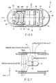
- FIG. 1 An explanation will be given on an encapsulated medical device guidance system according to one embodiment of the invention shown in FIG. 1 .
- This encapsulated medical device guidance system is largely divided into a capsule endoscope 21 shown in FIG. 2 - FIG. 6 , and a magnetic guidance unit 1 which generates a magnetic field for guiding a capsule endoscope.
- a capsule endoscope 21 is taken and explained as an example.
- the magnetic guidance unit 1 mainly comprises a guidance coil group (X1, X2, Y1, Y2, Z1, Z2, D1, D2, D3, D4, D5, D6, D7, D8), a power supply 2 for guidance coils, a guidance control unit 3, a controller 4, a sense coil unit 5 (5a - 5i), a position detector 6, a receiving antenna unit 7 (7a, 7b, 7c), an antenna selector 8, a receiving unit 9, a display unit 10, a drive coil 11, and a drive coil driver 12.
- a guidance coil group X1, X2, Y1, Y2, Z1, Z2, D1, D2, D3, D4, D5, D6, D7, D8
- a power supply 2 for guidance coils
- a guidance control unit 3 mainly comprises a guidance control unit 3, a controller 4, a sense coil unit 5 (5a - 5i), a position detector 6, a receiving antenna unit 7 (7a, 7b, 7c), an antenna selector 8, a receiving unit 9, a display unit 10, a drive coil 11, and
- Each of fourteen guidance coils X1, X2, Y1, Y2, Z1, Z2 and D1 - D8 has an air-core electromagnet, and forms an induction magnetic field generator.
- the guidance coils are arranged in each side of a rectangular parallelepiped.
- the direction of moving the capsule endoscope 21 forward and backward is assumed to be an X-axis direction
- the axis horizontally perpendicular to the X-axis direction is assumed to be a the Y-axis direction
- a gravitational axis vertically perpendicular to the X-axis direction is assumed be a Z-axis direction.
- the guidance coils X1 and X2 are placed opposing each other around the surfaces of front and rear sides, forming magnetic lines of force along the X-axis direction, and becoming vertical to the X-axis.
- the guidance coil X1 side is assumed to be the front
- the guidance coil X2 side is assumed to be the rear. Moving from the guidance coil X2 to the guidance coil X1 is assumed to be moving forward, and moving in the reverse direction is assumed to be moving backward.
- the guidance coils Y1 and Y2 are placed opposing each other around the surfaces of both sides, forming magnetic lines of force along the Y-axis direction, and becoming vertical to the Y-axis direction.
- two guidance coils D3 and D7 are arranged inside the guidance coil Y1 so as to divide the plane into two parts
- two guidance coils D1 and D5 are arranged inside the guidance coil Y2 so as to divide the plane into two parts.
- the guidance coils Z1 and Z2 are placed opposing each other around the top and bottom planes with respect to the Z-axis direction, forming magnetic lines of force along the Z-axis direction.
- two guidance coils D4 and D8 are arranged inside the guidance coil Z1 so as to divide the plane into two parts
- two guidance coils D2 and D6 are arranged inside the guidance coil Z2 so as to divide the plane into two parts.
- the guidance coil Z1 side is assumed to be the top
- the guidance coil Z2 side is assumed to be the bottom. Moving from the guidance coil Z2 to the guidance coil Z1 is assumed to be moving upward, and moving in the reverse direction is assumed to be moving downward.
- An alternating magnetic field formed by the drive coil 11 acts on the magnetic induction coil 31 and generates an induction current, and a magnetic field is generated from the magnetic induction coil.
- This alternating magnetic field includes one or more frequency components close to a resonance frequency generated by a coil (magnetic induction coil 31) and capacitor 33 described later provided in the capsule endoscope 21.
- the generated induction magnetic field is detected by the sense coils 5a - 5i, a signal including the position information is generated, and the signal is sent to the position detector 6. Based on this signal, the position detector calculates the position and posture information in the capsule endoscope 21. The position and attitude information is sent to the guidance control unit 3, and used for calculation of a magnetic field to be generated by the guidance coil group.
- the group of guidance coils X1, X2, Y1, Y2, Z1, Z2, and D1 - D8 is a first magnetic gradient generating means, which generates a magnetic gradient (a first magnetic gradient) to act on the magnet (magnetic substance) in the capsule endoscope 21, and pull the endoscope in a desired direction by moving longitudinally, horizontally and vertically.
- the guidance coil Z1 eliminates the influence of gravity when pulling the capsule endoscope 21 in a desired direction by moving up the endoscope by the above-mentioned guidance coil group, by generating a magnetic gradient (a second magnetic gradient) to act on the magnet in the capsule endoscope 21 to cancel the force of moving down the endoscope moved by the gravity.
- the guidance coils D4 and D8 can also generate the same force as the guidance coil Z1.
- the guidance coil Z1 is a second magnetic gradient generating means to eliminate the influence of gravity when moving the endoscope in a desired direction.
- the guidance coil Z2 eliminates the influence of buoyancy when pulling the capsule endoscope 21 in a desired direction by moving down the endoscope by the above-mentioned guidance coil group, by generating a magnetic to act on the magnet in the capsule endoscope 21 to cancel the force of moving up the endoscope moved by the buoyancy.
- the guidance coils D2 and D6 can also generate the same force as the guidance coil Z2.
- the opposingly placed guidance coils X1 and X2, Y1 and Y2, and Z1 and Z2 generate a uniform magnetic field within the space surrounded by these guidance coils when a magnetic field is generated in the same direction, and forms a gradient magnetic filed when a magnetic field is generated in the opposite direction.
- the coils S1 - D8 can form a highly uniform magnetic field or a gradient magnetic field by driving appropriately. Therefore, by controlling these fourteen guidance coils, it is possible to generate a magnetic field having desired intensity and gradient within a desired space.
- the guidance coil group in addition to moving the capsule endoscope 21 longitudinally, horizontally and vertically, it is possible to incline the endoscope to a position rising to the front, for example, by generating a magnetic field to tilt the distal end side up and proximal end side down, by combining the guidance coils X1, X2, Y1, Y2, Z1, Z2 and D1 - D8.
- These guidance coils are connected to the power supply 2 for guidance coils driven individually.
- the power supply 2 for guidance coils is controlled by the instruction from the guidance control unit 3, appropriately supplies power to an guidance coil necessary for generating a magnetic field, and generates a desired magnetic field in a desired space.
- Nine sense amplifiers 5a - 5i constituting the sense coil group 5 are arranged to be parallel to the side provided with the guidance coil Y1 and uniform in a plane, so that the correct position and attitude of the capsule endoscope 21 can be obtained.
- the position related to the Z-axis is detected by providing a pair of opposingly placed the sense coil group 5 and drive coil 11.
- the position detector 6 receives an instruction to specify a position information detection timing from the guidance control unit 3, and drives the drive coil driver 12 based on the instruction.
- the drive coil driver 12 generates a magnetic field by supplying an AC current to the drive coil 11, and generates an induction magnetic field in the capsule endoscope 21 in the magnetic field.
- Each sense coil of the sense coil group 5 detects a signal based on the induction magnetic field generated from the capsule endoscope 21, and outputs it to the position detector 6.
- the position detector 6 generates the position and attitude information of the capsule endoscope 21 from the signal based on the induction magnetic field, and outputs it to the guidance control unit 3.
- the guidance control unit 3 determines a desired moving direction considering the position and attitude information of the capsule endoscope 21 from the position detector 6, and instructs the power supply 2 for guidance coils to generate a magnetic field suitable for moving in that direction.
- the power supply 2 for guidance coils feeds a current to the guidance coils X1, X2, Y1, Y2, Z1, Z2 and D1 - D8 according to the instruction from the guidance control unit 3. Therefore, a magnetic field suitable for that moving is generated by the guidance coils, and the capsule endoscope 21 can be smoothly guided.
- the controller 4 is an input unit, which instructs the advancing direction and gradient of the capsule endoscope 21, by the operation of an input device by the operator, for example, tilting a joystick to a desired direction.
- an input device for example, tilting a joystick to a desired direction.
- buttons arranged to instruct all directions, a touch panel, or a line-of-sight input unit is available as a means to operate the controller 4.
- the guidance control unit 3 receives an instruction signal from the controller 4, position and attitude information from the position detector 6, and signals related to the driving states of the guidance coils from the receiving unit 9, calculates a magnetic force (a magnetic field) for moving the capsule endoscope 21 to a desired position, determines magnetic forces generated by the induction coils X1, X2, Y1, Y2, Z1, Z2 and D1 - D8 for generating the magnetic force, and sends an instruction to the power supply for each guidance coil.
- a magnetic force a magnetic field
- the guidance control unit 3 stops generation of a magnetic field during a communication period over which the image data taken by the capsule endoscope 21 is sent to the receiving unit 9. At the same time, during this communication period, the position detector 6 drives the drive coil 11 based on the instruction from the guidance control unit 3, and acquires position information from the sense coil group 5.
- Three receiving antennas 7 are connected to the receiving unit through an antenna selector 8 for selecting the antennas.
- These receiving antennas 7 consist of a receiving antenna 7a (AX) for receiving communication data (internal biological information including image data) from the X-axis direction, a receiving antenna 7b (AY) for receiving internal biological information from the Y-axis direction, and a receiving antenna 7c (AZ) for receiving internal biological information from the Z-axis direction.
- the receiving antennas 7 can detect internal biological information in three axis directions.
- the antenna selector 8 selects the antennas 7a, 7b and 7c to be used for communication.
- the antenna selector 8 receives the intensity, direction and gradient of a magnetic field generated by the guidance coil group at the position of each antenna, identifies a receiving antenna influenced minimum by the magnetic field, and selects that receiving antenna. By selecting such a receiving antenna 7, the communication between the receiving unit 9 and capsule endoscope 21 can be stabilized.
- the receiving unit 9 sends the guidance control unit 3 the timing of receiving internal biological information from the capsule endoscope 21.
- the guidance control unit 3 stops generation of an induction magnetic field by the guidance coil group and drive coil 11, during the communication period for sending internal biological information (image data). Due to this stoppage, the receiving unit can receive the internal biological information from the capsule endoscope 21 without being influenced by an induction magnetic field.
- the communication period does not overlap the moving operation and position detection period, and it is possible to eliminate a noise in the internal biological information caused by an induction magnetic field, or an influence of an induction magnetic field on the receiving antenna.
- this stop operation is useful in the point that image data is not influenced by a noise, and the receiving antenna is prevented from being influenced by an induction magnetic field, when a magnetic field generated close to the capsule endoscope 21 has high intensity and much gradient, or when a magnetic field generated close the receiving antenna 7 has high intensity and much gradient. Further, even if a magnetic field generated by the guidance coil has high intensity, the position detector 6 can be normally operated.
- the display unit 10 consists of a liquid crystal display, and displays an image taken by the capsule endoscope 21 received the receiving unit 9.
- the data such as photographing situation related to the displayed image may be displayed on the screen together with the image.
- FIG. 2 shows the sectional view showing the configuration of a first capsule endoscope according to the embodiment.
- a capsule case 23 of the first capsule endoscope 21 consists of a transparent semiround distal end case 23a placed in the front end side, and a cylindrical proximal end case 23b with a semiround rear end passing infrared rays.
- the capsule case 23 contains a capsule endoscope described later, and is enclosed watertight.
- the capsule endoscope 21 advances in the cylinder axial direction indicated by C in FIG. 2 .
- a main body of the capsule endoscope is largely divided into an image pickup unit to take pictures of the medial wall surface of a passage in an intracavital of a patient, a power supply unit to drive the image pickup unit, an induction magnetic field generator to generate an induction magnetic field by the above-mentioned drive coil 11, a magnet to drive the capsule endoscope 21, and a transmission unit to transmit internal biological information including acquired image data to the receiving antenna 7.
- the image pickup unit comprises a photographing optics 26 having a fixed-focus lens, an image pickup element 25 consisting of CMOS or CCD mounted on an image pickup side substrate 24a, an illumination unit 39 consisting of a light controllable LED provided close to the photographing optics 26, and an image processing circuit 27 to perform predetermined image processing for an image signal from the image pickup element 25 mounted on the image pickup side substrate 24a in the rear side of the image pickup element 25.
- the image pickup side substrate 24a, power supply side substrate 24b, and front side substrate 43 for a cell are sealed with adhesive as a single unit 29 fixed with an adhesive.
- the power supply unit comprises a small cell 32 consisting of a button cell, a pair of substrate 43 (43a and 43b) for a cell provided with a not-shown power supply terminal to take out power from the small cell 32, a heat-shrink tube 34 to fix the small cell 32 just like holding by the cell substrate, a power supply side substrate 24b whose circuit wiring is electrically connected to the circuit wiring of the image pickup side substrate 24 by a flexible substrate, and a power supply circuit 28 provided on the power supply side substrate 24b and powered by the small cell 32.
- the magnetic field generator comprises a magnet 30 provided on the perimeter of the adhesive fixed unit 29, a magnetic induction coil 31 provided through the magnet 30, and a capacitor 33 provided on the substrate for a cell in the front end side, composing a CL resonance circuit together with the magnetic induction coil 31.
- the magnetic induction coil 31 is shaped like a ring with a maximum outside diameter a little smaller than the inside diameter of the capsule case 23.
- the magnet 30 converges an external magnetic field in the magnetic induction coil 31.
- a material with high saturation magnetic flux density and permeability such as amorphous magnet and fine med (HITACHI KINNZOKU)
- HITACHI KINNZOKU amorphous magnet and fine med
- a circular drive magnet 42 is placed on the rear substrate 43b for a cell.
- a neodymium cobalt is suitable, but not limited to this material.
- the magnet 42 has an N-pole magnetized upward and a S-pole magnetized downward, so that the direction of magnetic lines of force becomes along the Z-axis direction.
- the transmission unit comprises a communication circuit 36 mounted on the rear side (the magnet 42 side) of a substrate 40 for transmission, an antenna 37 placed on the front surface side (the proximal end case 23b), a shielding part 35 to cover the exposed communication circuit 36 and to shield a magnetic force of the magnet 42, and an optical switch 38 which is mounted on the substrate 40 for transmission on the side provided with the antenna 27, and turns on/off the capsule endoscope.
- the magnetizing direction of the magnet 42 and the direction of the antenna 37 connected to the transmission circuit 36 are determined by changing the angle by 90 degree. This is done for establishing the condition that the magnetic field generated by the magnet 42 enters at an angle displaced 90 degree from the direction of the antenna 37. Therefore, the influence of the magnetic field from the magnet 42 upon the antenna 37 is reduced to minimum.
- the shielding part 35 is made of magnetic material, and has an effect to absorb the magnetic field close to the antenna 37. Therefore, the intensity of the magnetic field applied to the antenna 37 can be reduced, and the influence of the magnetic field on the radio communication between the transmission circuit 36 and antenna 37 can be decreased, and stable radio communication can be realized.
- the optical switch 38 is sensitive to infrared rays.
- the proximal end case 23b of the capsule case 23 is made of material to pass infrared rays (in the wavelength sensed by the optical switch) in at least the part close to the optical switch.
- infrared rays are applied to the optical switch 38 from a not-shown infrared rays emitter, the optical switch turns on, power is supplied from the small cell 32 through the power supply circuit, and photographing and transmission are started.
- the circuit of the optical switch 38 is configured to permit a toggle operation. Once infrared rays are applied, the capsule endoscope is kept on. It is permitted to add a configuration, which turns off the endoscope when infrared rays are applied in the on state.
- the influence of the strong magnetic field of the magnet 42 to the transmission circuit and radio circuit e.g., a noise is superposed, or a communicable distance is reduced
- clear image data with less noise can be sent to the receiving unit 9.
- FIG. 3 is a sectional view showing the configuration of a second capsule endoscope according to the embodiment.
- the second capsule endoscope is provided with a spiral part 41 formed by winding a wire with a circular cross section, on the perimeter of the capsule case 23, unlike the first capsule endoscope.
- the other parts are the same as the first capsule endoscope, and given the same reference numerals, and an explanation on these parts will be omitted.
- a revolving magnetic field to the second capsule endoscope is formed to a guidance coil group by the drive power supply from the power supply 2 for guidance coils, and the second capsule endoscope 21 is rotated about the axis C in the direction R as shown in FIG. 3 .
- the second capsule endoscope 21 is moved forward or backward along the axis C, according to the direction of rotating the spiral part 41. Further, as it is possible to rotate the second capsule endoscope 21 in the tilt position, the capsule endoscope can be moved forward or backward in the slanting direction.
- the second capsule endoscope configured as above provides the same function and effect as the first capsule endoscope.
- FIG. 4 is a sectional view showing the configuration of a third capsule endoscope according to the embodiment.
- the third capsule endoscope is configured by replacing the positions of the magnet 42 and the magnetic induction coil 31 in the first capsule endoscope.
- the other parts are the same as the first capsule endoscope, and given the same reference numerals, and an explanation on these parts will be omitted.
- FIG. 4 shows an example of configuration in which the induction coils 52 and 53 are placed in the directions of axes Z and Y. In the vicinity of the induction coils 52 and 53, capacitors 54 and 55 are placed to connect both ends of the induction coils for forming a LC resonance circuit, and adjusted to obtain a different resonance frequency.
- the crossed induction coils 52 and 53 generate an induction magnetic field by the magnetic field formed by the drive coil 11.
- the direction of the axis C i.e., the capsule endoscope advancing direction
- the direction of the axis C can be detected by obtaining the direction of each induction coil by a respective resonance frequency.
- a magnet 51 is arranged along the cylindrical axis (along the axis C) of the endoscope (with the N-pole set forward and S-pole set backward).
- a ring-shaped magnet or a barrel-shaped arrangement of stick magnets is provided on the perimeter of the bond fixed part 29.
- the third capsule endoscope configured as above can provide the same function and effect as the first capsule endoscope.
- FIG. 5 is a sectional view showing the configuration of a fourth capsule endoscope according to the embodiment.
- the fourth capsule endoscope is configured by replacing the magnet 42, transmission circuit 36 and antenna 37 in the first capsule endoscope.
- the other parts are the same as the first capsule endoscope, and given the same reference numerals, and an explanation on these parts will be omitted.
- the transmission circuit 36 and antenna 37 are enclosed by the shielding part 62, except the electromagnetic wave emitting direction of the antenna 37, a window for an optical switch is opened, and the optical switch 38 is placed there.
- a plurality of optical switch 38 may be provided in different directions.
- the shielding part is provided adjacent to the substrate 43b for a cell, and a magnet 63 equivalent to the magnet 42 in the first capsule endoscope is provided in the rear of the substrate.
- a proximal end case 61 of the capsule case 23 is shaped not semiround, but flat in the rear end. The rear end may be shaped semiround.
- the fourth capsule endoscope configured as above can provide the same function and effect as the first capsule endoscope. Further, with this configuration, the magnetic lines of force close to the antenna 37 can be decreased in the intensity by penetrating through the shielding part 62. Therefore, deterioration of transmission performance can be prevented by reducing the influence of the magnetic field generated by the magnet 63 on the antenna 37.
- the amount of magnetic flux entering the substrate can be decreased by evaporating a magnet as a shielding member, or by using a thin film forming technique such as sputtering. Therefore, the circuit formed in the capsule endoscope 21 can be prevented from malfunctioning due to an ill effect of a magnetic field of a magnet and guidance coil.
- FIG. 6 is a sectional view showing configuration of a fifth capsule endoscope according to the embodiment.
- the internal biological information (image data) is transmitted wirelessly (by radio waves) by using the communication circuit 36 and antenna 37.
- the fifth capsule endoscope uses a so-called electric field communication system. Namely, electrodes 64 and 65 exposed to the capsule case surface are provided, a current signal as internal biological information is flowed between the electrodes through an intracavital tissue as an examinee, thereby generating an electric field in a living organism, and the internal biological information is received by an electric field sensor fit to the body surface of a patient, instead of the receiving antenna.
- the other parts are the same as the first capsule endoscope, and given the same reference numerals, and an explanation on these parts will be omitted.
- radio waves are not used as a communication medium, an ill effect on the receiving unit and transmission line is eliminated, a noise is hardly superposed, and a stable clear image is obtained, in addition to the function and effect obtained by the first capsule endoscope.
- the communication circuit and antenna can be omitted, the configuration becomes simple, and the capsule case can be miniaturized furthermore.
- FIG. 7 is a view showing an example of magnetic lines of force in a magnetic field viewed from the Y-axis direction upon guidance, with respect to the first capsule endoscope shown in FIG. 2 .
- This magnetic field is formed in a space surrounded by the guidance coils Z1, Z2, D2, D4, D6 and D8.
- the capsule endoscope is placed in this space with the distal end facing the direction from the guidance coil X2 to guidance coil X1 (in the X-axis direction) shown in FIG. 6 .
- the guidance coil Z1 In this magnetic field, the guidance coil Z1 generates a magnetic force upward in the Z-axis direction as shown in the drawing.
- the capsule endoscope 21 generates a magnetic field with the intensity weak in the lower direction (the guidance coil Z2 side) and strong in the upper direction.
- the magnet 42 in the capsule endoscope 21 is given an attractive force in the direction of a strong magnetic field, i.e., upward (called here an upward attractive force).
- the capsule endoscope 21 is moved up in the space.
- the guidance control unit 3 By controlling the strength of the upward attractive force by the guidance control unit 3, it is possible to make the state that gravity acting upon the capsule endoscope 21 is cancelled.
- a magnetic field is formed in the guidance coils D2 and D4 as shown in FIG. 7 , and a pulling force for moving forward is generated. Therefore, when the magnetic fields of the guidance coils D2 and D4 are superposed on the magnetic field of the guidance coil Z1, the capsule endoscope 21 is moved forward while canceling the gravity acting on the endoscope itself.
- the capsule endoscope 21 is moved with its own weight (the mass of the capsule endoscope X acceleration of gravity) put on the intracavital tissue.
- the capsule endoscope 21 is reduced in its own weight, and moved in the state that a reaction force is weakened by viscosity, the endoscope can be equally moved even by a magnetic field with a lower intensity.
- this upward attractive force is excessively applied, the capsule endoscope 21 is unnecessarily floated from the intracavital tissue.
- the capsule endoscope 21 is floated from the intracavital tissue, the capsule endoscope comes close to the guidance coil Z1, the attractive force is weakened furthermore, and the capsule endoscope is suddenly attracted to the guidance coil Z1 and may be floated over the level desired by the user.
- FIG. 8(a) shows the intensity and generation timing of a magnetic field generated by the guidance coil Z1 to generate an upward attractive force in the Z-axis direction.
- FIG. 8(b) shows the intensity and generation timing of a magnetic field generated by the guidance coils D2 and D4 to generate a pulling force in the X-axis direction.
- FIG. 8(c) shows the timing for the position detector 6 to get signals (position and attitude information signals) based on the induction magnetic field, from each sense coil 5.
- FIG. 8(d) shows the timing of photographing internal biological information, and the timing of transmission and halt of transmission of internal biological information from the capsule endoscope 21 to the receiving unit 9.
- FIG. 8(e) shows the positions of the intracavital surface and endoscope in the Z-axis direction.
- the operation timing shown in FIG. 8 is set on the basis of the timing of photographing and transmitting image data by the capsule endoscope 21.
- the timing is not to be limited to this, and may be set as appropriate.
- the position of the capsule endoscope 21 is detected.
- the magnetic field intensity of the guidance coil Z1 is increased to raise the capsule endoscope (to n2) at the next timing.
- the intensity of generated magnetic field is lowered (n3) at the next timing.
- the relationship between the positions of the intracavital surface and capsule endoscope 21 in the Z-axis direction shown in FIG. 8(e) is conceptual, and actually, the capsule endoscope 21 substantially contacts the intracavital surface, and its weight is not substantially placed on the intracavital surface (the endoscope does not sink by its own weight).
- an upward magnetic field in the Z-direction as shown in FIG. 7 is generated in the guidance coils D2 and D4.
- This magnetic field increases the gradient in the direction from the guidance coil X2 to the guidance coil X1, and becomes a pulling force for the capsule endoscope 21 to be pulled forward along the X-axis direction. Therefore, the capsule endoscope 21 is pulled forward by the guidance coils D2 and D4 with the gravity cancelled by the magnetic field of the guidance coil Z1, and is smoothly moved with less friction on the intracavital surface.
- the magnetic field generated by the guidance coils D2 and D4 is increased in the gradient at the position of the capsule endoscope, and the pulling force is increased. Namely, the moving speed of the capsule endoscope is increased. To move the capsule endoscope 21 at a constant speed, it is necessary to keep the propulsive force constant. Therefore, the intensity of the magnetic field generated in the guidance coils D2 and D4 is gradually decreased as shown in FIG. 8(b) .
- the magnetic field intensity is controlled based on the position information of the capsule endoscope 21, the gravity applied to the endoscope is cancelled, and the frictional force acting between the capsule endoscope 21 and intracavital tissue is decreased.
- the operation of guiding the endoscope can be made easy by decreasing the resistance caused by the movement, and the endoscope can be equally moved by a magnetic field with a lower intensity.
- the intensity of a magnetic field is controlled by the number of applying an on signal with a predetermined short pulse width to a drive signal applied to the guidance coils Z1, D2 and D4 in a period over which one magnetic field is generated.
- a magnetic field is generated like a pulse in each guidance coil, the intervals between the generated magnetic fields are controlled, and the intensity of each magnetic field is controlled as a result. This is realized by adding a known switching circuit to the power supply 2 for guidance coils.
- the guidance coils Z1, D2 and D4 generate a magnetic field like a pulse, and the intensity of each magnetic field is controlled by controlling the intervals between the generated magnetic fields.
- the configuration of the power supply for guidance coils can be made simple.
- An equivalent control method can be realized by using a PWM (Pulse Width Modulation) control method, which controls the on time (pulse width).
- the third control method shown in FIG. 10 realizes similar movement of the capsule endoscope 21 by driving different combinations of guidance coils, unlike the first control method.
- the third capsule endoscope shown in FIG. 4 is suitable for the third control method.
- the magnet 51 is arranged along the cylindrical axis (in the direction of the axis C) of the endoscope (with the N-pole set forward and S-pole set backward).
- the magnetic induction coils 52 and 53 are crossed (here, perpendicular to each other), and each induction coil is also arranged perpendicular to the direction of the magnetic lines of force of the magnet 51.
- a wire is wound around a core made of a needle-like magnet, and the capacitors 54 and 55 are connected to the induction coils.
- the L-component or C-component of these two induction coils 52 and 53 is adjusted to have different resonance frequencies.
- the direction of magnetic lines of force from the magnet 51 can be arranged to be vertical to the longitudinal direction of the induction coils 52 and 53, and the influence of the magnetic field from the magnet 51 can be reduced to minimum, and the direction of the capsule endoscope can be determined by detecting the directions of two induction coils 52 and 53.
- the magnet incorporated in the capsule endoscope 21 shown in FIG. 10 is faced to the advancing direction (in the X-direction shown in FIG. 10 ) of the capsule endoscope 21, but the same control as shown in FIG. 7 is possible by adding a magnetic field as shown in FIG. 10 .
- a magnetic field as shown in FIG. 10 .
- the guidance coils D4 and D8 by generating a gradient magnetic field with the intensity gradually increased in the Z-axis direction (upward) by the guidance coils D4 and D8, an attractive force opposed to gravity is formed, and a gradient magnetic field is generated with the intensity gradually increased in the X-direction from the guidance coil X (the direction to the left side), and the capsule endoscope 21 can be moved in the X-direction with the gravity decreased.
- a first magnetic field advancing upward in the Z-axis direction is generated by using the guidance coils Z1 and Z2 among fourteen guidance coils X1, X2, Y, Y2, Z1, Z2, and D1 - D8, and a second magnetic field advancing to the left side in the X-axis direction is generated by using the guidance coils X1, and X2. It is possible to inline only the first magnetic field generated by the guidance coils Z1 and Z2.
- a magnetic field synthesized from the first and second magnetic fields is an external magnetic field H in FIG. 11 .
- the capsule endoscope 21 does not become parallel to the external magnetic field H.
- magnetization of the magnet 42 is assumed to be M
- the external magnetic field is assumed to be H
- the angle formed by M and H is assumed to be ⁇
- the mass of the capsule endoscope 21 is assumed to be m
- the gravity acceleration is assumed to be g
- the angle formed by the Z-direction and the direction of the capsule endoscope 21 is assumed to be ⁇
- the gravity of the capsule endoscope 21 is assumed to be G
- the pivot of rotation when the capsule endoscope 21 is faced upward and ⁇ is changed is assumed to be P
- the distance from the pivot P is assumed to be 1.
- the pivot P can be the center of the semiround shape of the exterior end portion on the side not provided with the image pickup optics 26 in the capsule endoscope 21.
- a magnetic field generated by the guidance coil group is controlled in this way.
- the capsule endoscope 21 can be directed to a desired direction (the ⁇ direction) without being influenced by gravity.
- an electric field is formed in the guidance coil X1 to generate an attractive force to pull in the forward direction, for example, while the capsule endoscope 21 is existing in the tilt position in such a magnetic field, the capsule endoscope 21 is moved forward while keeping the tilt position in the state that only the proximal end portion of the capsule case 23 contacts the medial wall of the digestive organs.
- the capsule endoscope By moving in this way, the capsule endoscope easily rides over an uneven spot on a pathway on the medial wall of the digestive organs. Further, by superposing an electric field to cancel gravity by using the guidance coil Z1, the capsule endoscope can be moved with a decreased frictional force.
- a desired position is realized by forming magnetic fields by a plurality of guidance coil.
- a guidance coil group X1/ X2 and Z1/Z2 are used to incline the capsule endoscope to the position as shown in FIG. 12 .
- the guidance coils Z1 and Z2 are used to form a third magnetic field toward the Z-axis downward, and the guidance coils Z1 and Z2 are used to form a fourth magnetic field toward the X-axis direction.
- a magnetic field to cancel the gravity applied to the capsule endoscope is formed, the magnetic field is superposed on a magnetic field to move the capsule endoscope or change the attitude of the capsule endoscope, the whole endoscope is floated to reduce the area to contact the intracavital surface, and a frictional resistance is decreased. Therefore, the capsule endoscope can be easily operated and controlled, an error in movement caused by gravity and sensed by the operator when the capsule endoscope is moved or the attitude of the endoscope can be eliminated, and the operation corresponding to the operating amount can be realized.
- the data transmission and position detection can be made without being influenced by the magnetic fields generated by the guidance coils, and the stability of the encapsulated medical device guidance system is improved.
- the capsule endoscope By controlling the attitude of the capsule endoscope, the capsule endoscope can be moved in the start-up tilt position with the distal end directed upward, and can easily ride over even an uneven area difficult to move on the intracavital surface on the pathway.
- Such movement in the tilt position with the distal end or proximal end portion contacting the intracavital surface can be realized by a magnetic field with the intensity lower than a magnetic field for floating the whole capsule endoscope, and a large output of a power supply for guidance coils is not required, and the capsule endoscope can be miniaturized.
- the present invention provides an encapsulated medical device guidance system, which generates a magnetic field environment for an encapsulated medical device to face to a desired direction, eliminates an error in movement caused by gravity acting during operation, decreases a frictional resistance, and works appropriately by a weak attractive force.
Priority Applications (2)
| Application Number | Priority Date | Filing Date | Title |
|---|---|---|---|
| EP11004808.9A EP2384687B1 (de) | 2005-12-27 | 2006-12-27 | System zum Führen einer verkapselten medizinischen Vorrichtung |
| EP10014249A EP2335559A1 (de) | 2005-12-27 | 2006-12-27 | System zum Führen einer verkapselten medizinischen Vorrichtung |
Applications Claiming Priority (2)
| Application Number | Priority Date | Filing Date | Title |
|---|---|---|---|
| JP2005376277 | 2005-12-27 | ||
| PCT/JP2006/326146 WO2007077896A1 (ja) | 2005-12-27 | 2006-12-27 | カプセル型医療装置誘導システム及びその制御方法 |
Related Child Applications (1)
| Application Number | Title | Priority Date | Filing Date |
|---|---|---|---|
| EP11004808.9A Division EP2384687B1 (de) | 2005-12-27 | 2006-12-27 | System zum Führen einer verkapselten medizinischen Vorrichtung |
Publications (2)
| Publication Number | Publication Date |
|---|---|
| EP1972253A1 true EP1972253A1 (de) | 2008-09-24 |
| EP1972253A4 EP1972253A4 (de) | 2010-03-03 |
Family
ID=38218110
Family Applications (4)
| Application Number | Title | Priority Date | Filing Date |
|---|---|---|---|
| EP10014249A Withdrawn EP2335559A1 (de) | 2005-12-27 | 2006-12-27 | System zum Führen einer verkapselten medizinischen Vorrichtung |
| EP06843528A Withdrawn EP1972253A4 (de) | 2005-12-27 | 2006-12-27 | Verkapseltes medizinprodukt-führungssystem und kontrollverfahren |
| EP06843530A Expired - Fee Related EP1972255B1 (de) | 2005-12-27 | 2006-12-27 | System zur führung eines kapselförmigen medizinprodukts und kontrollverfahren dafür |
| EP11004808.9A Expired - Fee Related EP2384687B1 (de) | 2005-12-27 | 2006-12-27 | System zum Führen einer verkapselten medizinischen Vorrichtung |
Family Applications Before (1)
| Application Number | Title | Priority Date | Filing Date |
|---|---|---|---|
| EP10014249A Withdrawn EP2335559A1 (de) | 2005-12-27 | 2006-12-27 | System zum Führen einer verkapselten medizinischen Vorrichtung |
Family Applications After (2)
| Application Number | Title | Priority Date | Filing Date |
|---|---|---|---|
| EP06843530A Expired - Fee Related EP1972255B1 (de) | 2005-12-27 | 2006-12-27 | System zur führung eines kapselförmigen medizinprodukts und kontrollverfahren dafür |
| EP11004808.9A Expired - Fee Related EP2384687B1 (de) | 2005-12-27 | 2006-12-27 | System zum Führen einer verkapselten medizinischen Vorrichtung |
Country Status (5)
| Country | Link |
|---|---|
| US (2) | US9039606B2 (de) |
| EP (4) | EP2335559A1 (de) |
| JP (2) | JP4891924B2 (de) |
| CN (3) | CN102688014B (de) |
| WO (2) | WO2007077896A1 (de) |
Cited By (8)
| Publication number | Priority date | Publication date | Assignee | Title |
|---|---|---|---|---|
| EP1891885A1 (de) * | 2006-08-21 | 2008-02-27 | Olympus Medical Systems Corp. | Kapselendoskop |
| EP1969989A1 (de) * | 2005-12-28 | 2008-09-17 | Olympus Medical Systems Corp. | System zur einführung in eine zu untersuchende person und beobachtungsverfahren in einer zu untersuchenden person |
| EP2135545A3 (de) * | 2008-06-19 | 2010-02-17 | Olympus Medical Systems Corporation | System und Verfahren zur magnetischen Navigation |
| WO2011076498A1 (de) * | 2009-12-23 | 2011-06-30 | Siemens Aktiengesellschaft | Spulensystem und verfahren zur berührungslosen magnetischen navigation eines magnetischen körpers in einem arbeitsraum |
| WO2011076497A1 (de) * | 2009-12-23 | 2011-06-30 | Siemens Aktiengesellschaft | Spulensystem und verfahren zur berührungslosen magnetischen navigation eines magnetischen körpers in einem arbeitsraum |
| EP2371263A1 (de) * | 2009-11-09 | 2011-10-05 | Olympus Medical Systems Corp. | Führungssystem für eine medizinische kapselartige vorrichtung und verfahren zur führung der medizinischen kapselartigen vorrichtung |
| US9601930B2 (en) | 2012-09-28 | 2017-03-21 | Broadcom Corporation | Power transmitting device having device discovery and power transfer capabilities |
| EP2393445B1 (de) * | 2009-02-05 | 2019-11-20 | Siemens Healthcare GmbH | Vorrichtung zum ablösen einer endoskopiekapsel von einer oberfläche einer flüssigkeit |
Families Citing this family (50)
| Publication number | Priority date | Publication date | Assignee | Title |
|---|---|---|---|---|
| CN101511258B (zh) * | 2006-09-14 | 2011-07-20 | 奥林巴斯医疗株式会社 | 医疗用引导系统以及医疗装置的控制方法 |
| WO2009022667A1 (ja) * | 2007-08-13 | 2009-02-19 | Olympus Medical Systems Corp. | 体内観察システムおよび体内観察方法 |
| JP5399253B2 (ja) * | 2007-09-26 | 2014-01-29 | オリンパスメディカルシステムズ株式会社 | 被検体内導入システム |
| DE102007051861B4 (de) * | 2007-10-30 | 2020-03-12 | Olympus Corporation | Verfahren zur Führung eines Kapsel-Endoskops und Endoskopsystem |
| DE102008008681A1 (de) | 2008-02-12 | 2009-09-03 | Siemens Aktiengesellschaft | Fahrwerkstraverse für ein Schienenfahrzeug |
| JP5121523B2 (ja) | 2008-03-24 | 2013-01-16 | オリンパスメディカルシステムズ株式会社 | 位置検出システム |
| DE102008018723B3 (de) * | 2008-04-14 | 2009-07-16 | Siemens Aktiengesellschaft | Verfahren zur Bewegungssteuerung einer Endoskopiekapsel |
| JP5248911B2 (ja) * | 2008-05-09 | 2013-07-31 | オリンパスメディカルシステムズ株式会社 | カプセル型医療装置 |
| JP5415717B2 (ja) * | 2008-06-19 | 2014-02-12 | オリンパスメディカルシステムズ株式会社 | 検査装置およびこれを用いた磁気誘導システム |
| JP5199020B2 (ja) * | 2008-10-17 | 2013-05-15 | オリンパスメディカルシステムズ株式会社 | 磁気誘導システムおよび磁気誘導システムの作動方法 |
| US8235888B2 (en) | 2008-07-08 | 2012-08-07 | Olympus Medical Systems Corp. | System for guiding capsule medical device |
| CN101623196B (zh) * | 2008-07-08 | 2013-04-03 | 奥林巴斯医疗株式会社 | 引导系统以及引导方法 |
| US20100010306A1 (en) * | 2008-07-08 | 2010-01-14 | Olympus Medical Systems Corp. | System for guiding capsule medical device |
| US8241206B2 (en) * | 2008-07-08 | 2012-08-14 | Olympus Medical Systems Corp. | System for guiding capsule medical device |
| DE102008049198B4 (de) * | 2008-09-26 | 2017-03-02 | Siemens Healthcare Gmbh | Spulensystem, medizinisches Gerät und Verfahren zur berührungslosen magnetischen Navigation eines magnetischen Körpers in einem Arbeitsraum |
| JP2010110432A (ja) * | 2008-11-05 | 2010-05-20 | Olympus Corp | 無線型被検体内情報取得装置 |
| EP2353489A4 (de) * | 2008-11-28 | 2015-11-25 | Olympus Corp | System zum führen einer verkapselten medizinischen vorrichtung |
| DE102009010286B3 (de) * | 2009-02-24 | 2010-11-25 | Siemens Aktiengesellschaft | Vorrichtung zum berührungslosen Führen eines Körpers in einem Arbeitsraum nebst zugehöriger Magnetfelderzeugungseinrichtung und zugehörigem magnetischen Körper |
| CN102421349B (zh) * | 2009-03-10 | 2015-08-12 | 奥林巴斯医疗株式会社 | 位置检测系统以及位置检测方法 |
| DE102009013354B4 (de) * | 2009-03-16 | 2011-02-17 | Siemens Aktiengesellschaft | Spulensystem, medizinische Vorrichtung sowie Verfahren zur berührungslosen magnetischen Navigation eines magnetischen Körpers in einem Arbeitsraum |
| DE102009013352B4 (de) * | 2009-03-16 | 2011-02-03 | Siemens Aktiengesellschaft | Spulenanordnungen zur Führung eines magnetischen Objekts in einem Arbeitsraum |
| JP4674276B1 (ja) * | 2009-11-09 | 2011-04-20 | オリンパスメディカルシステムズ株式会社 | カプセル型医療装置用誘導システム |
| EP2465408A4 (de) * | 2009-11-10 | 2014-11-05 | Olympus Medical Systems Corp | System zur führung einer medizinischen kapselvorrichtung und verfahren zur führung einer medizinischen kapselvorrichtung |
| WO2011072060A2 (en) * | 2009-12-08 | 2011-06-16 | Magnetecs Corporation | Diagnostic and therapeutic magnetic propulsion capsule and method for using the same |
| EP2347699B1 (de) * | 2010-01-22 | 2018-11-07 | Novineon Healthcare Technology Partners Gmbh | Kapselendoskop mit Magnetantrieb |
| DE102010006258A1 (de) | 2010-01-28 | 2011-08-18 | Siemens Aktiengesellschaft, 80333 | Verfahren zur berührungslosen magnetischen Navigation |
| WO2011102161A1 (ja) * | 2010-02-18 | 2011-08-25 | オリンパスメディカルシステムズ株式会社 | 位置検出システムおよび位置検出方法 |
| EP2471438A4 (de) * | 2010-03-05 | 2012-08-01 | Olympus Medical Systems Corp | Kapselartiges endoskop-hochfahrsystem |
| WO2011118253A1 (ja) * | 2010-03-26 | 2011-09-29 | オリンパスメディカルシステムズ株式会社 | カプセル型医療装置用誘導システムおよびカプセル型医療装置の誘導方法 |
| JP5259881B2 (ja) * | 2011-01-28 | 2013-08-07 | オリンパスメディカルシステムズ株式会社 | カプセル型医療装置用誘導システムおよび磁界発生装置 |
| DE102011004825B4 (de) * | 2011-02-28 | 2019-05-02 | Siemens Healthcare Gmbh | Verfahren zum Steuern des Transports einer ein magnetisches Moment aufweisenden Endoskopkapsel |
| DE102011078500B4 (de) * | 2011-07-01 | 2015-01-15 | Siemens Aktiengesellschaft | Verfahren und Einrichtung zur Steuerung einer Endoskopkapsel |
| KR101256408B1 (ko) * | 2011-08-25 | 2013-04-25 | 전남대학교산학협력단 | 마이크로로봇시스템 및 관형소화기관 검사용 캡슐형내시경시스템 |
| US10045713B2 (en) | 2012-08-16 | 2018-08-14 | Rock West Medical Devices, Llc | System and methods for triggering a radiofrequency transceiver in the human body |
| KR101410214B1 (ko) * | 2012-11-23 | 2014-06-20 | 전남대학교산학협력단 | 캡슐형 내시경 구동 제어시스템 및 이를 포함하는 캡슐형 내시경 시스템 |
| CN102973235A (zh) * | 2012-11-27 | 2013-03-20 | 深圳市资福技术有限公司 | 一种胶囊内窥镜及其方位控制装置 |
| CN103181748A (zh) * | 2012-12-20 | 2013-07-03 | 深圳市资福技术有限公司 | 一种胶囊内窥镜运行姿态的控制系统和控制方法 |
| CN105263391A (zh) * | 2013-03-11 | 2016-01-20 | 基文影像公司 | 操纵可吞入式体内装置的操纵线圈结构 |
| DK3060102T3 (da) | 2013-10-22 | 2021-06-07 | Rock West Medical Devices Llc | System til at lokalisere en pillesensor, der kan sluges, med tre sendeelementer |
| JP6521707B2 (ja) | 2014-07-10 | 2019-05-29 | キヤノン株式会社 | 穿刺プランニング装置及び穿刺システム |
| CN107072475A (zh) * | 2014-12-08 | 2017-08-18 | 奥林巴斯株式会社 | 胶囊型内窥镜系统 |
| JP6028132B1 (ja) * | 2015-01-06 | 2016-11-16 | オリンパス株式会社 | 誘導装置及びカプセル型医療装置誘導システム |
| JP6028131B1 (ja) * | 2015-03-30 | 2016-11-16 | オリンパス株式会社 | カプセル型内視鏡システムおよび磁界発生装置 |
| US10478047B2 (en) * | 2016-09-23 | 2019-11-19 | Ankon Medical Technologies (Shanghai) Co., Ltd | System and method for using a capsule device |
| CN110708998A (zh) * | 2017-06-13 | 2020-01-17 | 奥林巴斯株式会社 | 天线支架及天线单元 |
| CN211511733U (zh) * | 2019-06-17 | 2020-09-18 | 深圳硅基智控科技有限公司 | 胶囊内窥镜的磁控装置 |
| CN110638416B (zh) * | 2019-09-29 | 2022-06-21 | 北京华亘安邦科技有限公司 | 一种胶囊内镜的悬浮控制方法及装置 |
| CN111184497B (zh) * | 2020-04-08 | 2020-07-17 | 上海安翰医疗技术有限公司 | 胶囊内窥镜控制方法及系统 |
| CN112656353A (zh) * | 2021-02-01 | 2021-04-16 | 河南省中医院(河南中医药大学第二附属医院) | 一种防雾型肛肠内窥镜 |
| CN113100690A (zh) * | 2021-03-29 | 2021-07-13 | 谈斯聪 | 一种体内微型机器人装置、最优化治疗调控系统及方法 |
Citations (3)
| Publication number | Priority date | Publication date | Assignee | Title |
|---|---|---|---|---|
| US5681260A (en) * | 1989-09-22 | 1997-10-28 | Olympus Optical Co., Ltd. | Guiding apparatus for guiding an insertable body within an inspected object |
| US20020188174A1 (en) * | 1998-09-09 | 2002-12-12 | Olympus Optical Co., Ltd. | Endoscope shape detecting apparatus controlled according to connection state of magnetic field generating means |
| JP2003260026A (ja) * | 2002-03-08 | 2003-09-16 | Olympus Optical Co Ltd | 医療用磁気誘導装置 |
Family Cites Families (19)
| Publication number | Priority date | Publication date | Assignee | Title |
|---|---|---|---|---|
| US5654864A (en) * | 1994-07-25 | 1997-08-05 | University Of Virginia Patent Foundation | Control method for magnetic stereotaxis system |
| US6401723B1 (en) * | 2000-02-16 | 2002-06-11 | Stereotaxis, Inc. | Magnetic medical devices with changeable magnetic moments and method of navigating magnetic medical devices with changeable magnetic moments |
| AU2002307762A1 (en) * | 2001-04-18 | 2002-10-28 | Bbms Ltd. | Navigating and maneuvering of an in vivo vechicle by extracorporeal devices |
| DE10142253C1 (de) | 2001-08-29 | 2003-04-24 | Siemens Ag | Endoroboter |
| JP2004298560A (ja) * | 2003-04-01 | 2004-10-28 | Olympus Corp | カプセル内視鏡システム |
| JP4503930B2 (ja) * | 2003-01-30 | 2010-07-14 | オリンパス株式会社 | 医療装置 |
| JP4091004B2 (ja) | 2003-02-04 | 2008-05-28 | オリンパス株式会社 | 医療装置誘導システム |
| JP2004289560A (ja) * | 2003-03-24 | 2004-10-14 | Sony Corp | 画像記録再生方法および画像記録再生装置 |
| DE10340925B3 (de) * | 2003-09-05 | 2005-06-30 | Siemens Ag | Magnetspulensystem zur berührungsfreien Bewegung eines magnetischen Körpers in einem Arbeitsraum |
| DE10341092B4 (de) * | 2003-09-05 | 2005-12-22 | Siemens Ag | Anlage zur berührungsfreien Bewegung und/oder Fixierung eines magnetischen Körpers in einem Arbeitsraum unter Verwendung eines Magnetspulensystems |
| DE10343494B4 (de) * | 2003-09-19 | 2006-06-14 | Siemens Ag | Magnetisch navigierbare Einrichtung für den Einsatz auf dem Gebiet der medizinischen Endoskopie |
| DE10346678A1 (de) * | 2003-10-08 | 2005-05-12 | Siemens Ag | Endoskopieeinrichtung umfassend eine Endoskopiekapsel oder einen Endoskopiekopf mit einer Bildaufnahmeeinrichtung sowie Bildgebungsverfahren für eine solche Endoskopieeinrichtung |
| JP4414725B2 (ja) * | 2003-10-28 | 2010-02-10 | オリンパス株式会社 | カプセル型医療装置 |
| JP4515747B2 (ja) * | 2003-10-27 | 2010-08-04 | オリンパス株式会社 | カプセル型医療装置 |
| US7751866B2 (en) * | 2004-03-08 | 2010-07-06 | Olympus Corporation | Detecting system of position and posture of capsule medical device |
| JP5030392B2 (ja) * | 2004-06-14 | 2012-09-19 | オリンパス株式会社 | 医療装置の位置検出システムおよび医療装置誘導システム |
| CN1332629C (zh) * | 2004-09-02 | 2007-08-22 | 上海交通大学 | 主动式肠道内窥镜机器人系统 |
| DE102006010730A1 (de) * | 2005-03-17 | 2006-09-28 | Siemens Ag | Einrichtung zur Positions- und/oder Orientierungsbestimmung eines navigierbaren Objects |
| DE102007051861B4 (de) * | 2007-10-30 | 2020-03-12 | Olympus Corporation | Verfahren zur Führung eines Kapsel-Endoskops und Endoskopsystem |
-
2006
- 2006-12-27 EP EP10014249A patent/EP2335559A1/de not_active Withdrawn
- 2006-12-27 CN CN201210156822.XA patent/CN102688014B/zh not_active Expired - Fee Related
- 2006-12-27 EP EP06843528A patent/EP1972253A4/de not_active Withdrawn
- 2006-12-27 JP JP2007552971A patent/JP4891924B2/ja not_active Expired - Fee Related
- 2006-12-27 EP EP06843530A patent/EP1972255B1/de not_active Expired - Fee Related
- 2006-12-27 WO PCT/JP2006/326146 patent/WO2007077896A1/ja active Application Filing
- 2006-12-27 JP JP2007552018A patent/JP5042037B2/ja not_active Expired - Fee Related
- 2006-12-27 WO PCT/JP2006/326148 patent/WO2007074888A1/ja active Application Filing
- 2006-12-27 EP EP11004808.9A patent/EP2384687B1/de not_active Expired - Fee Related
- 2006-12-27 CN CN2006800496316A patent/CN101351143B/zh not_active Expired - Fee Related
- 2006-12-27 CN CN2006800496227A patent/CN101351141B/zh active Active
-
2008
- 2008-06-26 US US12/146,712 patent/US9039606B2/en not_active Expired - Fee Related
- 2008-06-26 US US12/147,262 patent/US20080306340A1/en not_active Abandoned
Patent Citations (3)
| Publication number | Priority date | Publication date | Assignee | Title |
|---|---|---|---|---|
| US5681260A (en) * | 1989-09-22 | 1997-10-28 | Olympus Optical Co., Ltd. | Guiding apparatus for guiding an insertable body within an inspected object |
| US20020188174A1 (en) * | 1998-09-09 | 2002-12-12 | Olympus Optical Co., Ltd. | Endoscope shape detecting apparatus controlled according to connection state of magnetic field generating means |
| JP2003260026A (ja) * | 2002-03-08 | 2003-09-16 | Olympus Optical Co Ltd | 医療用磁気誘導装置 |
Non-Patent Citations (1)
| Title |
|---|
| See also references of WO2007077896A1 * |
Cited By (17)
| Publication number | Priority date | Publication date | Assignee | Title |
|---|---|---|---|---|
| EP1969989A1 (de) * | 2005-12-28 | 2008-09-17 | Olympus Medical Systems Corp. | System zur einführung in eine zu untersuchende person und beobachtungsverfahren in einer zu untersuchenden person |
| EP1969989A4 (de) * | 2005-12-28 | 2011-05-04 | Olympus Medical Systems Corp | System zur einführung in eine zu untersuchende person und beobachtungsverfahren in einer zu untersuchenden person |
| US8790247B2 (en) | 2005-12-28 | 2014-07-29 | Olympus Medical Systems Corp. | Body-insertable device system and in-vivo observation method |
| US8162821B2 (en) | 2005-12-28 | 2012-04-24 | Olympus Medical Systems Corp. | Body-insertable device positioning system and in-vivo observation method |
| EP2484272A3 (de) * | 2005-12-28 | 2012-08-22 | Olympus Medical Systems Corp. | In den Körper einsetzbares Vorrichtungssystem und In-vivo-Beobachtungsverfahren |
| EP1891885A1 (de) * | 2006-08-21 | 2008-02-27 | Olympus Medical Systems Corp. | Kapselendoskop |
| US8419620B2 (en) | 2008-06-19 | 2013-04-16 | Olympus Medical Systems Corp. | Magnetically guiding system and magnetically guiding method |
| EP2135545A3 (de) * | 2008-06-19 | 2010-02-17 | Olympus Medical Systems Corporation | System und Verfahren zur magnetischen Navigation |
| US8968185B2 (en) | 2008-06-19 | 2015-03-03 | Olympus Medical Systems Corp. | Magnetically guiding system and magnetically guiding method |
| US8303485B2 (en) | 2008-06-19 | 2012-11-06 | Olympus Medical Systems Corp. | Magnetically guiding system and magnetically guiding method |
| EP2393445B1 (de) * | 2009-02-05 | 2019-11-20 | Siemens Healthcare GmbH | Vorrichtung zum ablösen einer endoskopiekapsel von einer oberfläche einer flüssigkeit |
| US8444550B2 (en) | 2009-11-09 | 2013-05-21 | Olympus Medical Systems Corp. | Capsule medical device guidance system and method for guiding capsule medical device |
| EP2371263A4 (de) * | 2009-11-09 | 2012-05-16 | Olympus Medical Systems Corp | Führungssystem für eine medizinische kapselartige vorrichtung und verfahren zur führung der medizinischen kapselartigen vorrichtung |
| EP2371263A1 (de) * | 2009-11-09 | 2011-10-05 | Olympus Medical Systems Corp. | Führungssystem für eine medizinische kapselartige vorrichtung und verfahren zur führung der medizinischen kapselartigen vorrichtung |
| WO2011076497A1 (de) * | 2009-12-23 | 2011-06-30 | Siemens Aktiengesellschaft | Spulensystem und verfahren zur berührungslosen magnetischen navigation eines magnetischen körpers in einem arbeitsraum |
| WO2011076498A1 (de) * | 2009-12-23 | 2011-06-30 | Siemens Aktiengesellschaft | Spulensystem und verfahren zur berührungslosen magnetischen navigation eines magnetischen körpers in einem arbeitsraum |
| US9601930B2 (en) | 2012-09-28 | 2017-03-21 | Broadcom Corporation | Power transmitting device having device discovery and power transfer capabilities |
Also Published As
| Publication number | Publication date |
|---|---|
| CN101351141B (zh) | 2011-07-13 |
| WO2007074888A1 (ja) | 2007-07-05 |
| EP1972255A1 (de) | 2008-09-24 |
| US20080294006A1 (en) | 2008-11-27 |
| US9039606B2 (en) | 2015-05-26 |
| US20080306340A1 (en) | 2008-12-11 |
| EP2384687A1 (de) | 2011-11-09 |
| CN102688014A (zh) | 2012-09-26 |
| WO2007077896A1 (ja) | 2007-07-12 |
| JP4891924B2 (ja) | 2012-03-07 |
| CN101351143A (zh) | 2009-01-21 |
| EP1972255A4 (de) | 2010-03-03 |
| JP5042037B2 (ja) | 2012-10-03 |
| EP1972253A4 (de) | 2010-03-03 |
| CN101351143B (zh) | 2012-07-04 |
| EP1972255B1 (de) | 2012-03-28 |
| JPWO2007077896A1 (ja) | 2009-06-11 |
| CN101351141A (zh) | 2009-01-21 |
| CN102688014B (zh) | 2015-03-18 |
| EP2335559A1 (de) | 2011-06-22 |
| EP2384687B1 (de) | 2016-05-11 |
| JPWO2007074888A1 (ja) | 2009-06-04 |
Similar Documents
| Publication | Publication Date | Title |
|---|---|---|
| EP2384687B1 (de) | System zum Führen einer verkapselten medizinischen Vorrichtung | |
| JP4827525B2 (ja) | カプセル型医療装置誘導システム | |
| KR100889160B1 (ko) | 자기 안내 의료 장치 | |
| EP1955644B1 (de) | System zum nachweis der position eines medizinprodukts, führungssystem für ein medizinprodukt und verfahren zum nachweis der position eines medizinprodukts | |
| JP2007175188A5 (de) | ||
| US8187166B2 (en) | Minimally invasive medical system employing a magnetically controlled endo-robot | |
| US20130331649A1 (en) | Magnetically maneuverable in-vivo device | |
| JP4542326B2 (ja) | カプセル型医療装置誘導システム | |
| EP2561797B1 (de) | Mikrorobotersystem und Kapselendoskopsystem zur Prüfung eines röhrenförmigen Verdauungsapparats |
Legal Events
| Date | Code | Title | Description |
|---|---|---|---|
| PUAI | Public reference made under article 153(3) epc to a published international application that has entered the european phase |
Free format text: ORIGINAL CODE: 0009012 |
|
| 17P | Request for examination filed |
Effective date: 20080723 |
|
| AK | Designated contracting states |
Kind code of ref document: A1 Designated state(s): DE FR GB |
|
| RIN1 | Information on inventor provided before grant (corrected) |
Inventor name: AOKI, ISAOC Inventor name: KIMURA, ATSUSHIC Inventor name: UCHIYAMA, AKIOC |
|
| DAX | Request for extension of the european patent (deleted) | ||
| RBV | Designated contracting states (corrected) |
Designated state(s): DE FR GB |
|
| A4 | Supplementary search report drawn up and despatched |
Effective date: 20100129 |
|
| 17Q | First examination report despatched |
Effective date: 20100423 |
|
| DAC | Divisional application: reference to earlier application (deleted) | ||
| STAA | Information on the status of an ep patent application or granted ep patent |
Free format text: STATUS: THE APPLICATION IS DEEMED TO BE WITHDRAWN |
|
| 18D | Application deemed to be withdrawn |
Effective date: 20110618 |