EP1970098A2 - Steuerung für Ultraschalltherapiegerät - Google Patents
Steuerung für Ultraschalltherapiegerät Download PDFInfo
- Publication number
- EP1970098A2 EP1970098A2 EP08012090A EP08012090A EP1970098A2 EP 1970098 A2 EP1970098 A2 EP 1970098A2 EP 08012090 A EP08012090 A EP 08012090A EP 08012090 A EP08012090 A EP 08012090A EP 1970098 A2 EP1970098 A2 EP 1970098A2
- Authority
- EP
- European Patent Office
- Prior art keywords
- controller
- ultrasound
- ultrasonic transducer
- processor
- treatment
- Prior art date
- Legal status (The legal status is an assumption and is not a legal conclusion. Google has not performed a legal analysis and makes no representation as to the accuracy of the status listed.)
- Withdrawn
Links
- 238000009210 therapy by ultrasound Methods 0.000 title claims description 6
- 238000011282 treatment Methods 0.000 claims abstract description 79
- 238000002604 ultrasonography Methods 0.000 claims abstract description 44
- 230000005669 field effect Effects 0.000 claims description 7
- 239000004020 conductor Substances 0.000 claims description 5
- 238000012163 sequencing technique Methods 0.000 claims description 3
- 230000001143 conditioned effect Effects 0.000 claims 2
- 230000000007 visual effect Effects 0.000 claims 2
- 239000003990 capacitor Substances 0.000 description 11
- 230000008878 coupling Effects 0.000 description 6
- 238000010168 coupling process Methods 0.000 description 6
- 238000005859 coupling reaction Methods 0.000 description 6
- 230000001276 controlling effect Effects 0.000 description 5
- 238000010586 diagram Methods 0.000 description 5
- 230000006870 function Effects 0.000 description 5
- 238000000034 method Methods 0.000 description 5
- 208000027418 Wounds and injury Diseases 0.000 description 4
- 238000002161 passivation Methods 0.000 description 4
- PEDCQBHIVMGVHV-UHFFFAOYSA-N Glycerine Chemical compound OCC(O)CO PEDCQBHIVMGVHV-UHFFFAOYSA-N 0.000 description 3
- 230000008901 benefit Effects 0.000 description 3
- 230000002354 daily effect Effects 0.000 description 3
- 230000006378 damage Effects 0.000 description 3
- 230000000694 effects Effects 0.000 description 3
- 238000004146 energy storage Methods 0.000 description 3
- 230000035876 healing Effects 0.000 description 3
- 208000014674 injury Diseases 0.000 description 3
- 239000004973 liquid crystal related substance Substances 0.000 description 3
- 239000000463 material Substances 0.000 description 3
- WHXSMMKQMYFTQS-UHFFFAOYSA-N Lithium Chemical compound [Li] WHXSMMKQMYFTQS-UHFFFAOYSA-N 0.000 description 2
- 238000006243 chemical reaction Methods 0.000 description 2
- 238000009434 installation Methods 0.000 description 2
- 229910052744 lithium Inorganic materials 0.000 description 2
- 230000000737 periodic effect Effects 0.000 description 2
- 230000008569 process Effects 0.000 description 2
- 210000004872 soft tissue Anatomy 0.000 description 2
- 238000011269 treatment regimen Methods 0.000 description 2
- 238000012935 Averaging Methods 0.000 description 1
- 208000010392 Bone Fractures Diseases 0.000 description 1
- 230000003213 activating effect Effects 0.000 description 1
- 230000004913 activation Effects 0.000 description 1
- 230000009286 beneficial effect Effects 0.000 description 1
- 230000001186 cumulative effect Effects 0.000 description 1
- 230000007547 defect Effects 0.000 description 1
- 230000003111 delayed effect Effects 0.000 description 1
- 238000001514 detection method Methods 0.000 description 1
- 230000003203 everyday effect Effects 0.000 description 1
- 230000001747 exhibiting effect Effects 0.000 description 1
- 230000003721 exogen phase Effects 0.000 description 1
- 239000012467 final product Substances 0.000 description 1
- 230000000774 hypoallergenic effect Effects 0.000 description 1
- 239000006210 lotion Substances 0.000 description 1
- 230000007257 malfunction Effects 0.000 description 1
- 230000007246 mechanism Effects 0.000 description 1
- 230000005055 memory storage Effects 0.000 description 1
- 239000000203 mixture Substances 0.000 description 1
- 230000004048 modification Effects 0.000 description 1
- 238000012986 modification Methods 0.000 description 1
- 239000003921 oil Substances 0.000 description 1
- 238000003359 percent control normalization Methods 0.000 description 1
- 230000001902 propagating effect Effects 0.000 description 1
- 230000001105 regulatory effect Effects 0.000 description 1
- 230000000630 rising effect Effects 0.000 description 1
- 230000001225 therapeutic effect Effects 0.000 description 1
- 210000002303 tibia Anatomy 0.000 description 1
- 210000001519 tissue Anatomy 0.000 description 1
- 210000000689 upper leg Anatomy 0.000 description 1
- XLYOFNOQVPJJNP-UHFFFAOYSA-N water Substances O XLYOFNOQVPJJNP-UHFFFAOYSA-N 0.000 description 1
Images


Classifications
-
- A—HUMAN NECESSITIES
- A61—MEDICAL OR VETERINARY SCIENCE; HYGIENE
- A61B—DIAGNOSIS; SURGERY; IDENTIFICATION
- A61B8/00—Diagnosis using ultrasonic, sonic or infrasonic waves
- A61B8/42—Details of probe positioning or probe attachment to the patient
- A61B8/4272—Details of probe positioning or probe attachment to the patient involving the acoustic interface between the transducer and the tissue
- A61B8/4281—Details of probe positioning or probe attachment to the patient involving the acoustic interface between the transducer and the tissue characterised by sound-transmitting media or devices for coupling the transducer to the tissue
-
- A—HUMAN NECESSITIES
- A61—MEDICAL OR VETERINARY SCIENCE; HYGIENE
- A61B—DIAGNOSIS; SURGERY; IDENTIFICATION
- A61B8/00—Diagnosis using ultrasonic, sonic or infrasonic waves
- A61B8/42—Details of probe positioning or probe attachment to the patient
- A61B8/4209—Details of probe positioning or probe attachment to the patient by using holders, e.g. positioning frames
- A61B8/4227—Details of probe positioning or probe attachment to the patient by using holders, e.g. positioning frames characterised by straps, belts, cuffs or braces
-
- A—HUMAN NECESSITIES
- A61—MEDICAL OR VETERINARY SCIENCE; HYGIENE
- A61N—ELECTROTHERAPY; MAGNETOTHERAPY; RADIATION THERAPY; ULTRASOUND THERAPY
- A61N7/00—Ultrasound therapy
-
- B—PERFORMING OPERATIONS; TRANSPORTING
- B06—GENERATING OR TRANSMITTING MECHANICAL VIBRATIONS IN GENERAL
- B06B—METHODS OR APPARATUS FOR GENERATING OR TRANSMITTING MECHANICAL VIBRATIONS OF INFRASONIC, SONIC, OR ULTRASONIC FREQUENCY, e.g. FOR PERFORMING MECHANICAL WORK IN GENERAL
- B06B1/00—Methods or apparatus for generating mechanical vibrations of infrasonic, sonic, or ultrasonic frequency
- B06B1/02—Methods or apparatus for generating mechanical vibrations of infrasonic, sonic, or ultrasonic frequency making use of electrical energy
- B06B1/0207—Driving circuits
- B06B1/0223—Driving circuits for generating signals continuous in time
- B06B1/0238—Driving circuits for generating signals continuous in time of a single frequency, e.g. a sine-wave
- B06B1/0246—Driving circuits for generating signals continuous in time of a single frequency, e.g. a sine-wave with a feedback signal
-
- H—ELECTRICITY
- H02—GENERATION; CONVERSION OR DISTRIBUTION OF ELECTRIC POWER
- H02J—CIRCUIT ARRANGEMENTS OR SYSTEMS FOR SUPPLYING OR DISTRIBUTING ELECTRIC POWER; SYSTEMS FOR STORING ELECTRIC ENERGY
- H02J7/00—Circuit arrangements for charging or depolarising batteries or for supplying loads from batteries
- H02J7/00032—Circuit arrangements for charging or depolarising batteries or for supplying loads from batteries characterised by data exchange
- H02J7/00036—Charger exchanging data with battery
-
- H—ELECTRICITY
- H02—GENERATION; CONVERSION OR DISTRIBUTION OF ELECTRIC POWER
- H02J—CIRCUIT ARRANGEMENTS OR SYSTEMS FOR SUPPLYING OR DISTRIBUTING ELECTRIC POWER; SYSTEMS FOR STORING ELECTRIC ENERGY
- H02J7/00—Circuit arrangements for charging or depolarising batteries or for supplying loads from batteries
- H02J7/00047—Circuit arrangements for charging or depolarising batteries or for supplying loads from batteries with provisions for charging different types of batteries
-
- A—HUMAN NECESSITIES
- A61—MEDICAL OR VETERINARY SCIENCE; HYGIENE
- A61B—DIAGNOSIS; SURGERY; IDENTIFICATION
- A61B17/00—Surgical instruments, devices or methods
- A61B17/22—Implements for squeezing-off ulcers or the like on inner organs of the body; Implements for scraping-out cavities of body organs, e.g. bones; for invasive removal or destruction of calculus using mechanical vibrations; for removing obstructions in blood vessels, not otherwise provided for
- A61B17/225—Implements for squeezing-off ulcers or the like on inner organs of the body; Implements for scraping-out cavities of body organs, e.g. bones; for invasive removal or destruction of calculus using mechanical vibrations; for removing obstructions in blood vessels, not otherwise provided for for extracorporeal shock wave lithotripsy [ESWL], e.g. by using ultrasonic waves
- A61B17/2251—Implements for squeezing-off ulcers or the like on inner organs of the body; Implements for scraping-out cavities of body organs, e.g. bones; for invasive removal or destruction of calculus using mechanical vibrations; for removing obstructions in blood vessels, not otherwise provided for for extracorporeal shock wave lithotripsy [ESWL], e.g. by using ultrasonic waves characterised by coupling elements between the apparatus, e.g. shock wave apparatus or locating means, and the patient, e.g. details of bags, pressure control of bag on patient
- A61B2017/2253—Implements for squeezing-off ulcers or the like on inner organs of the body; Implements for scraping-out cavities of body organs, e.g. bones; for invasive removal or destruction of calculus using mechanical vibrations; for removing obstructions in blood vessels, not otherwise provided for for extracorporeal shock wave lithotripsy [ESWL], e.g. by using ultrasonic waves characterised by coupling elements between the apparatus, e.g. shock wave apparatus or locating means, and the patient, e.g. details of bags, pressure control of bag on patient using a coupling gel or liquid
-
- H—ELECTRICITY
- H02—GENERATION; CONVERSION OR DISTRIBUTION OF ELECTRIC POWER
- H02J—CIRCUIT ARRANGEMENTS OR SYSTEMS FOR SUPPLYING OR DISTRIBUTING ELECTRIC POWER; SYSTEMS FOR STORING ELECTRIC ENERGY
- H02J2310/00—The network for supplying or distributing electric power characterised by its spatial reach or by the load
- H02J2310/10—The network having a local or delimited stationary reach
- H02J2310/20—The network being internal to a load
- H02J2310/23—The load being a medical device, a medical implant, or a life supporting device
Definitions
- This disclosure relates to the generation of ultrasound signals and, more particularly, to an ultrasonic controller for use with an ultrasonic transducer to accelerate the process of healing in both hard and soft tissue.
- the therapeutic value of ultrasonic waves is known.
- Various techniques and devices are used to apply ultrasound waves to various areas of the body.
- a pulsed radio-frequency ultrasonic signal applied via a transducer to the skin of a patient and is directed to the site of the wound.
- the radio-frequency signal is in the range of 1.3 to 2 MHZ, and it consists of pulses at a repetition rate of 100 to 1000 Hz, with each pulse having a duration in the range of 10 to 20,000 microseconds. See, e.g. U.S. Patent No. 4,530,360 to Duarte and U.S. Patent No. 5,520,612 to Winder et al .
- U.S. Patent Nos. 5,003,965 and 5,186,162 both to Talish and Lifshey describe an ultrasonic delivery system where the R-F generator and transducer are both part of a modular applicator unit that is placed at the skin location. The signals controlling the duration of ultrasonic pulses and the pulse repetition frequency are generated apart from the applicator unit.
- Talish '965 and Talish '162 also describe fixture apparatus for attaching the applicator unit so that the operative surface is adjacent the skin location. In Talish '965 and Talish '162, the skin is surrounded by a cast, while in U.S. Patent No.
- Talish '160 5,211,160 to Talish and Lifshey fixture apparatus is described for mounting on uncovered body parts (i.e., without a cast or other medical wrapping).
- Talish '160 also describes various improvements to the applicator unit.
- Duarte, Talish '965, Talish '162 and Talish '160, are all incorporated into this application by reference.
- an ultrasonic wave coupling material e.g. a conductive gel
- a conductive gel is used between the surface of the skin and the transducer head. If an inadequate amount of gel is used or it is improperly applied by the patient to herself, the treatment session will not be as effective as it should be. Therefore, a need exists for determining whether or not a gel layer is properly applied or even if the patient forgets to apply the gel before treatment.
- Ultrasonic treatment systems are made up of many components. Variations in component tolerances in the output driver circuitry or the output transducer, for example, create a need to perform minor adjustments to the output power level in order to achieve the required level of compliance. Although a manual tuning component traditionally works, its use requires a labor intensive process which can raise the cost of the final product. Therefore, a need to reliably set power levels and perform minor adjustments for ultrasonic transducers exists.
- a controller for driving an ultrasonic transducer includes a processor, responsive to a feedback signal, for generating control signals to an output driver which is responsive to the control signals, to cause the ultrasonic transducer to generate ultrasound having a power level corresponding to the control signal.
- the controller is preferably attached to a sensing circuit to determine the presence of a sufficient amount of ultrasound conductive gel associated with the ultrasonic transducer, and for generating the feedback signal therefrom.
- the controller includes data logging capabilities to record treatment data and prevent inappropriate treatment delivery.
- the processor creates the desired operating frequency.
- the controller creates an environment for a simple, safe and efficient ultrasonic self-treatment by patients.
- the microprocessor used in the controller creates the operating frequency and can warn of a low battery condition or insufficient amount of ultrasound conducting gel. It can limit the usage of the transducer to prevent over treatment by comparing use data with acceptable limits and disabling the transducer if the limits have been exceeded. It can also be used as a switching regulator to improve lithium battery life.
- the device is contemplated to be portable for ease of transport by patients and can be configured for use with a wide variety of power supplies at a number of different anatomical treatment sites.
- An ultrasound delivery controller system for driving ultrasonic transducers includes a plurality of controller boards, each board for controlling an ultrasound transducer wherein one of the plurality of boards is a master board for controlling and sequencing the other boards.
- the present invention includes the use of a microprocessor to receive and output electrical signals from a feedback circuit and to an ultrasonic transducer:
- the microprocessor can receive signals from a sensing circuit and produce a warning sign to the user of the ultrasonic treatment device.
- the microprocessor can be used to log treatment times and intervals between treatments.
- the microprocessor can also be used to output varying power levels to the ultrasonic transducer.
- a compliance indicator may also be provided to, inter alia, inform the patient as to whether they have been complying with the prescribed treatment regimen.
- the microprocessor can be input with treatment, use and/or control parameters to facilitate, e.g., compliance, return and/or disabling of the unit.
- the microprocessor can be programmed for 1 treatment sequence, two or more sequences or an unlimited number of sequences.
- the microprocessor can also limit the number of times per day the unit can be used to avoid potential misuse. Further details are described herein.
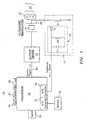
- FIG. 1 shows a schematic diagram of an ultrasonic transducer controller 10 with an AC current detector circuit 12 connected to an ultrasonic transducer 14.
- the transducer controller includes a processor 16, which could be a microprocessor used in conjunction with an ultrasonic transducer 14.
- the processor 16 generates control signals which are amplified by an output driver 18 to the desired power level and imparted to the ultrasonic transducer 14.
- a preferred transducer could be an air backed quarter wave matched transducer.
- the delivery of ultrasound to a target 20 requires an efficient coupling path between the transducer and the patient's skin and soft tissue.
- a material for ultrasound coupling is used, typical characteristics include coupling, hypoallergenic composition and slow to dry. Commonly used materials are sonically conductive materials, such as glycerol, water, oils, lotions, etc.
- a layer of gel 22 is preferred and often used to effect a proper interface for propagating ultrasonic waves 24 into the body 20.
- the application of gel to the surface of an ultrasonic transducer changes the acoustic load impedance on the transducer such that the electrical current flowing through the transducer tends to be reduced. If gel is absent or present in an insufficient amount, the current through the transducer will be excessive.
- the amount of current flowing through the transducer can be used as an indicator as to whether gel is available to couple the ultrasonic waves through the interface between the transducer and the patient's body. Conversely, if no current is flowing (zero current) then there may have been a malfunction of the transducer or more often of a cable or connection to the transducer. Also, because ultrasound is reflected from the gel/tissue media, a receiver can be used to sense reflected ultrasound signals. If little or no reflected signal is received, an insufficient gel signal can be given.
- the detector circuit 12 is in series with the transducer 14.
- a current sensing resistor R1 is connected between a transducer side which contacts a patient's skin and electrical common. When current flows through the transducer, it induces a proportional but small voltage across the current sensing resistor R1. This voltage will be referenced to common since the current sensing resistor R1 is connected to electrical common.
- the current sensing function of R1 can be performed with either an inductor or a capacitor to provide an equivalent impedance magnitude as R1. Whereas the resistor is dissipative, the inductor or capacitor is nearly without loss. This has the advantage of saving battery power.
- the current sensing resistor R1 is wired in parallel with a peak detector circuit 24.
- the peak detector circuit 24 includes a diode D1 in series with a capacitor C1 and resistor R2 which are in parallel with one another.
- the peak detector circuit 24 is also referenced to common.
- the purpose of the peak detector circuit 24 is to rectify the periodic alternating voltage across the current sensing resistor R1.
- the alternating signal is filtered and a proportional DC magnitude is derived.
- the diode D1 rectifies the signal, capacitor C1 smooths the DC signal and resistor R2 discharges C1 when there is no signal on R1.
- the equivalent function of R2 can be performed in the processor 16 if the A/D sense port for A/D converter 26 can be selectively changed to a digital ground to discharge C1.
- the DC signal's magnitude can be sampled by the processor 16 to determine if adequate gel is present or if the transducer 14 is not functioning.
- One method of detection includes the conversion of the analog DC magnitude, or the feedback signal, into a digital value through the use of an analog to digital converter 26 (herein A/D converter).
- A/D converter 26 is shown integrated with the processor 16. Alternately, the A/D converter 26 can be placed on a printed circuit board (not shown) along with other components of the processor 16.
- the software code is preferably encrypted for security.
- the feedback signal is read from a connection point between the diode D1 and C1 of the peak detector circuit.
- the feedback signal is proportional to the transducer current and is a function of the motional impedance of the transducer which varies as a function of the acoustic impedance at the face of the transducer 28.
- the processor 16 senses the acoustic impedance through the analog to digital conversion from the current detector circuit 12. The motional impedance will be lowest with good skin contact at the face of the transducer. If an unsatisfactory acoustic coupling is detected, the user is given an indication by means of an alarm, for example a light emitting diode 34 on the unit next to the word "GEL".
- FIG. 1A shows an alternative embodiment of the gel sensing means wherein a reflected signal receiver 31 is used to receive a reflected portion of an ultrasound signal. If a reflected signal of insufficient magnitude is received, a low gel warning is generated and the signal can be suspended.
- a processor or microprocessor 16 and transducer 14 can be powered by an energy storage device 30, such as a battery. It is therefore necessary to give a patient warning when the energy storage device runs low.
- an energy storage device 30 such as a battery.
- the power from the energy storage device 30 is sampled.
- the value of the voltage is converted from an analog signal to a digital signal by means of an A/D converter 32.
- the digital signal can be compared to a predetermined value stored in the memory of the microprocessor 16. If the energy source is low an alarm is activated, such as a liquid crystal display 36, indicating "Bat Low", for example, or a light emitting diode.
- the transducer controller can be activated by a switch 38 or a button located on or near the processor.
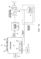
- FIG. 2 is a schematic of the transducer controller 10 with digital output ports connected to an output driver 18.
- Output bits b 0 , b 1 , and b 2 can be generated by the microprocessor 16 or stored in the microprocessor's memory for retrieval at the appropriate time.
- the bits represent a high or low voltage ("1" or "0", respectively).
- Output bits b 0 , b 1 and b 2 are passed through resistors having a magnitude proportional to the bits place value, thereby creating more current for a given bit value of "1". For example a "high" bit on line b 3 generates a current proportionally greater than a "high” on line b 1 because the resistance in the line is greater at b 1 .
- the resistors, R3, R4, R5 and diode D2 are connected to the same node, or control signal line 40, to produce an ultrasound control signal proportional to the output bits.
- the control signal line is connected to common through a capacitor C2.
- the control signal line current can be varied by the line resistances R3, R4 and R5 which set the charging rate of the capacitor C2.
- R idle sets a minimum charge rate.
- C2 drives the voltage in the control signal line 40 which is then amplified by an output driver 18. Different charge rates of capacitor C2 create varied power levels in the transducer 14 once the signal is amplified. The amount of variation of the signal can be controlled by the word size at the output of the controller.
- the control signal must be amplified prior to being applied across the transducer 14. Any stable AC voltage amplifier providing a gain in the range of about 3 to 5 and capable of driving a 50 ⁇ load is possible.
- the amplifier could contain a Field Effect Transistor (FET) having its gate coupled to the control signal line 40.
- FET Field Effect Transistor
- Diode D2 can be connected between the b idle bit output and an end of the capacitor C2 opposite the common connection. D2 would allow for a fast discharge of C2 once a predetermined time has elapsed which may be determined by the digital bits cyclically switching to OFF. This would disable the output driver 18 and, therefore, the transducer.
- a switching regulator 70 may be connected to L1 of the output driver 18 and the resistors at a node A.
- the switching regulator 70 is powered by battery 30 and controlled by the processor 16, i.e., turned on for treatment and off for sleep.
- the switching regulator 70 enables the use of any size battery because the output voltage supplied, V variable supply , can be regulated. Thus, alkaline batteries, etc. can be used. Typical batteries provide 6-12 volts.
- Using the regulator allows the battery voltage to be adjusted to a higher value, for example, 10-15 volts. This enables a higher voltage to be supplied to the output driver 18 for ultrasound treatment.
- the output of switching regulator 70 may be set by adjusting the values of the resistors R3-R5, for example.
- a CMOS digital buffer 72 may be included.
- the buffer 72 includes two invertors which are connected in-line on the control signal line 40.
- Control signal line 40 connects to the FET of the output driver 18.
- the buffer 72 increases the switching efficiency of FET.
- the buffer switches from low to high when the control signal amplitude as shown in FIG. 3 rises to approximately 50% full amplitude and off when falling below approximately 50% control signal amplitude. In this manner, the slowly rising control signals in FIG. 3 are converted to a pulse width modulated square wave drive signal for the FET.
- the buffer 72 is more temperature stable since it comprises CMOS transistors and reduces the temperature dependency of the FET for switching the output driver 18 on and off. This is advantageous in a battery powered system since battery power is conserved in efficiently switched systems.
- the sensing circuit can provide an estimate of and control the input power to the transducer 14.
- the circuit includes a current sensor, a voltage sensor, a multiplier and an averaging circuit, such as a low pass filter.
- the analog power estimate at the output of the averager is converted to a digital signal by means of the A/D converter 26 in the processor 16. This digital value can then be compared to a stored reference and the differential used to adjust the control signal to the FET of the output driver, thereby controlling the acoustic power output of the transducer to within prescribed limits.
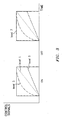
- FIG. 3 shows a time plot of several control signals corresponding to a given output power level.
- the power level numbers correspond to the example outlined in TABLE 1, above.
- the highest power level, 7, is achieved by the fastest charge up of capacitor C2.
- the y-axis represents voltage, for example, and is limited by the capacitor C2 and other circuit parameters. The maximum voltage is achieved quickly when the largest charging current corresponding to the highest bit word value is encountered. For intermediate power settings charging the capacitor is delayed resulting in a shorter duty cycle as shown in FIG. 3 .
- FIG. 4 demonstrates a memory allocation scheme for recording the time of treatment and the interval between treatments.
- An optimized daily treatment time has been shown to be a consistent 20 minute session. The effects of longer daily treatments (over 20 minutes per session) are not in the overall treatment plan for a patient. Therefore, a mechanism for ensuring correct treatment time is desirable.
- Information recording can be employed through processor memory.
- An electrically erasable programmable read only memory (EEPROM) device (not shown) could be used, for example.
- Each recorded entry consists of 3 bytes or 24 bits of memory.
- a first byte 42 (8 bits) would contain the number of whole days that have elapsed since the previous treatment. Eight (8) bits allow the storage of an integer numbers form 0 to 255.
- the number of days exceeds 255 than it can be recorded as 255. This can also be used as an indicator to disable the unit after a set number of days. For example if treatment is to be for 3 weeks, a limit of 21 may be used in conjunction with a rule in software to disable the unit.
- a second byte 44 and part of a third byte 48a can be used to store the number of minutes that have elapsed since the last treatment. Eleven (11) bits are capable of storing an integer from 0 to 2047. Since there are only 1440 minutes in a day, only the integers 0 to 1439 are needed in these bits. In this way the number of days and minutes is recorded since the last treatment session. The remaining five (5) bits of the 24 would represent the amount of time in minutes of a given session. The five bits can contain an equivalent binary number from 0 to 31, of which only 0 to 20 would be needed since the time of the session would be monitored by software to automatically end the session at 20 minutes.
- the data collected by the processor 16 can be used to not only log the patient's treatment, but also to prevent the patient from extending the treatment.
- a first counter (not shown) is provided in the processor that allows a patient to reinitiate a session that has been interrupted. Once a patient begins a new 20 minute treatment session, a four hour clock is started. If the patient is interrupted during the session the remaining treatment time remains available to continue treatment within the four hour time limit. When the four hour time period expires the patient can no longer receive treatment and the remaining time left in the session is no longer available. For example, a patient begins a new 20 minute treatment session, after 10 minutes the patient is interrupted. The remaining ten minutes of treatment must be used within the next 3 hours and 50 minutes or that treatment time is lost.
- Counters (not shown) on the processor can keep track of treatment frequency and disable the transducer if the patient attempts treatment sessions within the 12 hour period or 2 times in 36 hours. For example, if a patient desires to move up a treatment session by 12 hours from the normally prescribed 24 hour period, it is possible. However, he must wait 24 hours before the next treatment can be performed to satisfy the requirement of a maximum of 2 sessions per 36 hour period.
- a further use for the processor includes providing a means for defining the number of treatments a given unit can perform without being recharged or reprogrammed.
- a unit is programmed using an EEPROM, which does not require battery power, to store a set number of sessions or the total amount of time available to the patient. Different types of injuries may require a different number of treatment sessions.
- an electronic key input code
- a smart battery a battery which identifies itself by an input code
- the processor may also include programming which requires prepayment prior to activation or payment prior to or contemporaneous with a treatment or sequence of treatments. This feature could facilitate return of the unit and avoid potential unauthorized use.
- an end-of-file disabling program can be provided which inactivates/disables the unit after a predetermined number of uses and/or the passage of a predetermined time period.
- FIG. 5 and 6 show a preferred embodiment of the controller in practical use.
- the processor 16, output driver 18, battery 30, sensing circuit 12 and related circuitry (not shown in FIGS. 5 and 6 ) can all be assembled into housing 54.
- a "GEL" alarm 62, a "BAT LOW” alarm 66 and a compliance indicator 67 can be positioned on top of the housing 54 in plain view of the patient.
- a power button 64 can be located on the housing for easy access by the patient.
- FIG. 5 shows the ultrasonic transducer head 50 prior to installation within an insert 52 which is mounted in a cast 60.
- the unit 68 can be secured to the patient by straps 56.
- a flexible cable 58 can be used to connect the unit 68 to transducer head 50.
- FIG. 6 shows the transducer head 50 installed in the insert 52 and secured by a cover 62.
- the insert 52 and therefore the transducer head 50 are located over the injured area and the ultrasound conductive material (not shown) is placed between the transducer
- unit 68 is configurable into different housings.
- Ultrasonic transducer controller 10 ( FIG. 1 ) may be included within commercially available devices, for example an SAFHS 2000 available commercially from Exogen, Inc, Piscataway, NJ. Ultrasonic transducer controller 10 ( FIG. 1 ) may be configured with appropriate inputs and outputs to work with or control the SAFHS 2000 unit in accordance with the present invention.
- the microprocessor of the present invention is also contemplated for use in passivation of the battery power supply.
- Lithium batteries while exhibiting long shelf life, on the order of about 8 years are subject to oxide buildup which increases the internal resistance of the battery. When the internal resistance increases to a point where there is insufficient current to drive the controller, the unit will not function.
- the microprocessor senses this oxide layer buildup, also referred to as the passivation layer, and applies a resistance less than the resistance of the controller to effectively burn off at least a portion of the passivation layer thus permitting full operation of the controller without the need to replace the battery.
- the microprocessor can be provided with two clock circuits with one circuit assigned to time keeping and the other circuit activating the processor at a reduced power level on a periodic basis to clear the passivation layer.
- the processor could be activated once a day to run for about 5 seconds at a power level of 100 mA. This step keeps the battery chemistry in good operating condition and maximizes useful battery life.
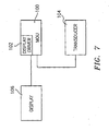
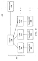
- a main operating unit 100 includes a liquid crystal display (LCD) interface board or display driver 102.
- a transducer 104 connects to unit 100 where feedback is processed and transferred to board 102 and output to a liquid crystal display 106.
- Display 106 is preferably mounted on unit 100. Information displayed on display 106 includes treatment time elapsed or remaining, number of days left in the treatment regimen, warnings or error messages, etc.
- a plurality of controller boards 202 may be included in a main operating unit 200.
- a master board 204 is included and comprises circuitry for controlling, synchronizing and or sequencing slave boards 206. Each board controls outputs to a transducer 208.
- Transducers 208 may be positioned about a treatment site to form an array of transducers appropriately located to better treat an injury, for example at different locations about a patient's thigh to treat a tibia. Transducers 208 are sequenced so as to minimize interference between ultrasound waves supplied by each transducer.
- master board 204 supplied time shifted enable signals to slave boards 206 to provide time staggering treatment delivery from different transducers. In a preferred embodiment, time shifts between transducers are between about 200 microseconds to about 800 microseconds.
Landscapes
- Health & Medical Sciences (AREA)
- Life Sciences & Earth Sciences (AREA)
- Engineering & Computer Science (AREA)
- Physics & Mathematics (AREA)
- Veterinary Medicine (AREA)
- Nuclear Medicine, Radiotherapy & Molecular Imaging (AREA)
- Radiology & Medical Imaging (AREA)
- Biomedical Technology (AREA)
- Animal Behavior & Ethology (AREA)
- General Health & Medical Sciences (AREA)
- Public Health (AREA)
- Pathology (AREA)
- Biophysics (AREA)
- Heart & Thoracic Surgery (AREA)
- Medical Informatics (AREA)
- Molecular Biology (AREA)
- Surgery (AREA)
- Power Engineering (AREA)
- Mechanical Engineering (AREA)
- Acoustics & Sound (AREA)
- Percussion Or Vibration Massage (AREA)
- Surgical Instruments (AREA)
- Ultra Sonic Daignosis Equipment (AREA)
- Apparatuses For Generation Of Mechanical Vibrations (AREA)
Applications Claiming Priority (3)
| Application Number | Priority Date | Filing Date | Title |
|---|---|---|---|
| US09/040,157 US6261249B1 (en) | 1998-03-17 | 1998-03-17 | Ultrasonic treatment controller including gel sensing circuit |
| EP05008868A EP1566201B1 (de) | 1998-03-17 | 1999-03-17 | Steuerung für Ultraschalltherapiegerät |
| EP99913930A EP1064053B1 (de) | 1998-03-17 | 1999-03-17 | Steuerung für ultraschalltherapiegerät |
Related Parent Applications (3)
| Application Number | Title | Priority Date | Filing Date |
|---|---|---|---|
| EP05008868A Division EP1566201B1 (de) | 1998-03-17 | 1999-03-17 | Steuerung für Ultraschalltherapiegerät |
| EP99913930.6 Division | 1999-03-17 | ||
| EP05008868.1 Division | 2005-04-22 |
Publications (2)
| Publication Number | Publication Date |
|---|---|
| EP1970098A2 true EP1970098A2 (de) | 2008-09-17 |
| EP1970098A3 EP1970098A3 (de) | 2011-05-25 |
Family
ID=21909434
Family Applications (3)
| Application Number | Title | Priority Date | Filing Date |
|---|---|---|---|
| EP05008868A Expired - Lifetime EP1566201B1 (de) | 1998-03-17 | 1999-03-17 | Steuerung für Ultraschalltherapiegerät |
| EP99913930A Expired - Lifetime EP1064053B1 (de) | 1998-03-17 | 1999-03-17 | Steuerung für ultraschalltherapiegerät |
| EP08012090A Withdrawn EP1970098A3 (de) | 1998-03-17 | 1999-03-17 | Steuerung für Ultraschalltherapiegerät |
Family Applications Before (2)
| Application Number | Title | Priority Date | Filing Date |
|---|---|---|---|
| EP05008868A Expired - Lifetime EP1566201B1 (de) | 1998-03-17 | 1999-03-17 | Steuerung für Ultraschalltherapiegerät |
| EP99913930A Expired - Lifetime EP1064053B1 (de) | 1998-03-17 | 1999-03-17 | Steuerung für ultraschalltherapiegerät |
Country Status (9)
| Country | Link |
|---|---|
| US (1) | US6261249B1 (de) |
| EP (3) | EP1566201B1 (de) |
| JP (1) | JP4088417B2 (de) |
| AT (2) | ATE299738T1 (de) |
| AU (1) | AU763050B2 (de) |
| CA (1) | CA2324007C (de) |
| DE (2) | DE69940173D1 (de) |
| ES (2) | ES2245825T3 (de) |
| WO (1) | WO1999047209A1 (de) |
Cited By (1)
| Publication number | Priority date | Publication date | Assignee | Title |
|---|---|---|---|---|
| US10086216B2 (en) | 2010-10-12 | 2018-10-02 | Smith & Nephew, Inc. | Medical device |
Families Citing this family (71)
| Publication number | Priority date | Publication date | Assignee | Title |
|---|---|---|---|---|
| US7108663B2 (en) | 1997-02-06 | 2006-09-19 | Exogen, Inc. | Method and apparatus for cartilage growth stimulation |
| US7789841B2 (en) | 1997-02-06 | 2010-09-07 | Exogen, Inc. | Method and apparatus for connective tissue treatment |
| US5904659A (en) | 1997-02-14 | 1999-05-18 | Exogen, Inc. | Ultrasonic treatment for wounds |
| DE69933555T2 (de) | 1998-05-06 | 2007-06-14 | Exogen, Inc., Memphis | Ultraschallbandagen |
| WO2000004831A1 (en) | 1998-07-21 | 2000-02-03 | Acoustic Sciences Associates | Synthetic structural imaging and volume estimation of biological tissue organs |
| JP4132682B2 (ja) | 1999-05-21 | 2008-08-13 | エクソジェン インコーポレイテッド | 超音波および電磁気による組織治療装置および方法 |
| CA2377866A1 (en) | 1999-06-14 | 2000-12-21 | Roger J. Talish | Method and kit for cavitation-induced tissue healing with low intensity ultrasound |
| US7024248B2 (en) * | 2000-10-16 | 2006-04-04 | Remon Medical Technologies Ltd | Systems and methods for communicating with implantable devices |
| US7283874B2 (en) | 2000-10-16 | 2007-10-16 | Remon Medical Technologies Ltd. | Acoustically powered implantable stimulating device |
| US6764446B2 (en) | 2000-10-16 | 2004-07-20 | Remon Medical Technologies Ltd | Implantable pressure sensors and methods for making and using them |
| JP4126228B2 (ja) | 2000-10-25 | 2008-07-30 | エクソジェン インコーポレイテッド | 変換器取付用組立体 |
| US6893435B2 (en) * | 2000-10-31 | 2005-05-17 | Gyrus Medical Limited | Electrosurgical system |
| US6507210B1 (en) * | 2000-11-22 | 2003-01-14 | Ulysses Esd, Inc. | System and method for power testing a chassis |
| US7387612B2 (en) * | 2001-03-28 | 2008-06-17 | Cybersonics, Inc. | Floating probe for ultrasonic transducers |
| US7429248B1 (en) | 2001-08-09 | 2008-09-30 | Exogen, Inc. | Method and apparatus for controlling acoustic modes in tissue healing applications |
| CA2543725A1 (en) * | 2002-10-28 | 2004-05-06 | John Perrier | Ultrasonic medical device |
| JP2006521902A (ja) * | 2003-03-31 | 2006-09-28 | ライポソニックス, インコーポレイテッド | 渦型トランスデューサー |
| US7857773B2 (en) * | 2003-12-30 | 2010-12-28 | Medicis Technologies Corporation | Apparatus and methods for the destruction of adipose tissue |
| CA2546265A1 (en) * | 2003-12-30 | 2005-07-21 | Liposonix, Inc. | Systems and methods for the destruction of adipose tissue |
| JP2007516810A (ja) * | 2003-12-30 | 2007-06-28 | ライポソニックス, インコーポレイテッド | 動作制御を有する超音波治療ヘッド |
| US20050193451A1 (en) * | 2003-12-30 | 2005-09-01 | Liposonix, Inc. | Articulating arm for medical procedures |
| US20050154308A1 (en) * | 2003-12-30 | 2005-07-14 | Liposonix, Inc. | Disposable transducer seal |
| US20050154309A1 (en) * | 2003-12-30 | 2005-07-14 | Liposonix, Inc. | Medical device inline degasser |
| US8337407B2 (en) * | 2003-12-30 | 2012-12-25 | Liposonix, Inc. | Articulating arm for medical procedures |
| US10219815B2 (en) | 2005-09-22 | 2019-03-05 | The Regents Of The University Of Michigan | Histotripsy for thrombolysis |
| US20080306388A1 (en) * | 2006-01-06 | 2008-12-11 | Smith & Nephew, Inc. | Non-Strap Treatment Applicator |
| US8078278B2 (en) | 2006-01-10 | 2011-12-13 | Remon Medical Technologies Ltd. | Body attachable unit in wireless communication with implantable devices |
| US20070249938A1 (en) * | 2006-04-20 | 2007-10-25 | Donald J. Shields | Systems, devices, and methods employing therapeutic ultrasound of living tissues |
| US8038622B2 (en) * | 2007-08-03 | 2011-10-18 | Innoscion, Llc | Wired and wireless remotely controlled ultrasonic transducer and imaging apparatus |
| US9295444B2 (en) | 2006-11-10 | 2016-03-29 | Siemens Medical Solutions Usa, Inc. | Transducer array imaging system |
| US20080114251A1 (en) * | 2006-11-10 | 2008-05-15 | Penrith Corporation | Transducer array imaging system |
| US8142200B2 (en) * | 2007-03-26 | 2012-03-27 | Liposonix, Inc. | Slip ring spacer and method for its use |
| WO2008118908A1 (en) | 2007-03-26 | 2008-10-02 | Remon Medical Technologies, Ltd. | Biased acoustic switch for implantable medical device |
| US9070856B1 (en) | 2007-06-14 | 2015-06-30 | Misonix, Incorporated | Waveform generator for driving electromechanical device |
| US8659208B1 (en) | 2007-06-14 | 2014-02-25 | Misonix, Inc. | Waveform generator for driving electromechanical device |
| FR2920083B1 (fr) * | 2007-08-21 | 2011-01-14 | Michel Trezon | Dispositif d'epilation autonome, compact et miniaturise pour detruire les poils par lumiere pulsee |
| US20090240146A1 (en) * | 2007-10-26 | 2009-09-24 | Liposonix, Inc. | Mechanical arm |
| US9672471B2 (en) | 2007-12-18 | 2017-06-06 | Gearbox Llc | Systems, devices, and methods for detecting occlusions in a biological subject including spectral learning |
| US20100036269A1 (en) * | 2008-08-07 | 2010-02-11 | Searete Llc, A Limited Liability Corporation Of The State Of Delaware | Circulatory monitoring systems and methods |
| US9717896B2 (en) | 2007-12-18 | 2017-08-01 | Gearbox, Llc | Treatment indications informed by a priori implant information |
| AU2009208982B2 (en) | 2008-02-01 | 2013-07-04 | Solta Medical, Inc. | Therapy head for use with an ultrasound system |
| WO2009158062A1 (en) | 2008-06-27 | 2009-12-30 | Cardiac Pacemakers, Inc. | Systems and methods of monitoring the acoustic coupling of medical devices |
| US7812504B1 (en) | 2008-06-27 | 2010-10-12 | Microtrend Systems Inc. | Apparatus for high efficiency, high safety ultrasound power delivery with digital efficiency indicator and one clock cycle shutdown |
| CN102171337A (zh) | 2008-08-26 | 2011-08-31 | 智能纳米股份有限公司 | 用超声波方法促进动物细胞生长 |
| US8962290B2 (en) | 2008-08-26 | 2015-02-24 | Intelligentnano Inc. | Enhanced animal cell growth using ultrasound |
| US9012192B2 (en) | 2008-08-26 | 2015-04-21 | Intelligentnano Inc. | Ultrasound enhanced growth of microorganisms |
| DE112008004008T5 (de) | 2008-08-29 | 2011-06-30 | Harmonic Drive Systems Inc. | Wellgetriebe mit einem zusammengesetzten Zahnprofil, das bei positiver Verformung eingreift |
| JP5492903B2 (ja) | 2008-10-27 | 2014-05-14 | カーディアック ペースメイカーズ, インコーポレイテッド | 植込型装置を充電するための方法およびシステム |
| US20100217161A1 (en) * | 2009-02-25 | 2010-08-26 | Avi Shalgi | Delivery of therapeutic focused energy |
| US9844333B2 (en) | 2009-03-24 | 2017-12-19 | International Business Machines Corporation | Remote delivery and monitoring of health care |
| WO2011074061A1 (ja) * | 2009-12-14 | 2011-06-23 | キヤノン株式会社 | 超音波制御装置及び記録材判別装置 |
| CA2815474C (en) * | 2010-10-22 | 2019-10-29 | Kevin J. Tanis | Medical device |
| AU2011354720A1 (en) * | 2011-01-14 | 2013-05-30 | Debra Ann Arrington | Medical device with temperature sensor |
| DE102011115906A1 (de) * | 2011-10-14 | 2013-04-18 | Wellcomet Gmbh | System zum Erzeugen von Ultraschallwellen und Verfahren zur Konfiguration eines Ultraschallsystems |
| US11406415B2 (en) | 2012-06-11 | 2022-08-09 | Tenex Health, Inc. | Systems and methods for tissue treatment |
| WO2014105725A1 (en) | 2012-12-28 | 2014-07-03 | Volcano Corporation | Intravascular ultrasound imaging apparatus, interface architecture, and method of manufacturing |
| KR102107728B1 (ko) * | 2013-04-03 | 2020-05-07 | 삼성메디슨 주식회사 | 휴대용 초음파 장치, 휴대용 초음파 시스템 및 초음파 진단 방법 |
| US10780298B2 (en) | 2013-08-22 | 2020-09-22 | The Regents Of The University Of Michigan | Histotripsy using very short monopolar ultrasound pulses |
| US9504471B2 (en) | 2013-09-25 | 2016-11-29 | Cybersonics, Inc. | Ultrasonic generator systems and methods |
| KR102243037B1 (ko) | 2014-03-18 | 2021-04-21 | 삼성메디슨 주식회사 | 초음파 진단 장치 및 그 동작방법 |
| US9962181B2 (en) | 2014-09-02 | 2018-05-08 | Tenex Health, Inc. | Subcutaneous wound debridement |
| US10268229B2 (en) * | 2014-12-23 | 2019-04-23 | Zoll Medical Corporation | Adjustable electrical equipment |
| CN104682515A (zh) * | 2015-03-06 | 2015-06-03 | 中山智芯电子科技有限公司 | 一种热疗保健的移动电源 |
| ES2948135T3 (es) | 2015-06-24 | 2023-08-31 | Univ Michigan Regents | Sistemas de terapia de histotripsia para el tratamiento del tejido cerebral |
| CN110115054B (zh) * | 2016-11-29 | 2022-11-15 | P&P超G有限公司 | 防止设备的未授权使用 |
| US10571435B2 (en) | 2017-06-08 | 2020-02-25 | Covidien Lp | Systems and methods for digital control of ultrasonic devices |
| CA3084318A1 (en) * | 2017-12-08 | 2019-06-13 | Neural Analytics, Inc. | Systems and methods for gel management |
| CN120324803A (zh) | 2018-11-28 | 2025-07-18 | 希斯托索尼克斯公司 | 组织摧毁术系统及方法 |
| AU2021332372A1 (en) | 2020-08-27 | 2023-03-16 | The Regents Of The University Of Michigan | Ultrasound transducer with transmit-receive capability for histotripsy |
| EP4608504A1 (de) | 2022-10-28 | 2025-09-03 | Histosonics, Inc. | Histotripsiesysteme und -verfahren |
| AU2024257180A1 (en) | 2023-04-20 | 2025-09-18 | Histosonics, Inc. | Histotripsy systems and associated methods including user interfaces and workflows for treatment planning and therapy |
Citations (5)
| Publication number | Priority date | Publication date | Assignee | Title |
|---|---|---|---|---|
| US4530360A (en) | 1981-11-19 | 1985-07-23 | Duarte Luiz R | Method for healing bone fractures with ultrasound |
| US5003965A (en) | 1988-09-14 | 1991-04-02 | Meditron Corporation | Medical device for ultrasonic treatment of living tissue and/or cells |
| US5186162A (en) | 1988-09-14 | 1993-02-16 | Interpore Orthopaedics, Inc. | Ultrasonic transducer device for treatment of living tissue and/or cells |
| US5211160A (en) | 1988-09-14 | 1993-05-18 | Interpore Orthopaedics, Inc. | Ultrasonic orthopedic treatment head and body-mounting means therefor |
| US5520612A (en) | 1994-12-30 | 1996-05-28 | Exogen, Inc. | Acoustic system for bone-fracture therapy |
Family Cites Families (11)
| Publication number | Priority date | Publication date | Assignee | Title |
|---|---|---|---|---|
| US4441486A (en) | 1981-10-27 | 1984-04-10 | Board Of Trustees Of Leland Stanford Jr. University | Hyperthermia system |
| US4708127A (en) | 1985-10-24 | 1987-11-24 | The Birtcher Corporation | Ultrasonic generating system with feedback control |
| AU7752587A (en) | 1986-09-29 | 1988-04-21 | Dynawave Corporation | Ultrasound therapy device |
| US5184605A (en) | 1991-01-31 | 1993-02-09 | Excel Tech Ltd. | Therapeutic ultrasound generator with radiation dose control |
| US5314401A (en) | 1991-03-29 | 1994-05-24 | Amei Technologies Inc. | Conformable PEMF transducer |
| DE4125950C1 (de) | 1991-08-06 | 1992-11-05 | Dornier Medizintechnik Gmbh, 8000 Muenchen, De | |
| US5415167A (en) | 1992-01-10 | 1995-05-16 | Wilk; Peter J. | Medical system and associated method for automatic diagnosis and treatment |
| US5541489A (en) | 1994-12-15 | 1996-07-30 | Intel Corporation | Smart battery power availability feature based on battery-specific characteristics |
| US5556372A (en) | 1995-02-15 | 1996-09-17 | Exogen, Inc. | Apparatus for ultrasonic bone treatment |
| GB2303552A (en) | 1995-07-24 | 1997-02-26 | Gar Investment Corp | Ultrasound apparatus for non invasive cellulite reduction |
| US5699803A (en) * | 1996-08-09 | 1997-12-23 | Emerson Electric Co. | Method of performing ultrasonic examination |
-
1998
- 1998-03-17 US US09/040,157 patent/US6261249B1/en not_active Expired - Lifetime
-
1999
- 1999-03-17 DE DE69940173T patent/DE69940173D1/de not_active Expired - Lifetime
- 1999-03-17 EP EP05008868A patent/EP1566201B1/de not_active Expired - Lifetime
- 1999-03-17 AT AT99913930T patent/ATE299738T1/de active
- 1999-03-17 ES ES99913930T patent/ES2245825T3/es not_active Expired - Lifetime
- 1999-03-17 AT AT05008868T patent/ATE418361T1/de not_active IP Right Cessation
- 1999-03-17 WO PCT/US1999/005856 patent/WO1999047209A1/en not_active Ceased
- 1999-03-17 JP JP2000536442A patent/JP4088417B2/ja not_active Expired - Fee Related
- 1999-03-17 EP EP99913930A patent/EP1064053B1/de not_active Expired - Lifetime
- 1999-03-17 EP EP08012090A patent/EP1970098A3/de not_active Withdrawn
- 1999-03-17 DE DE69926221T patent/DE69926221T2/de not_active Expired - Lifetime
- 1999-03-17 CA CA2324007A patent/CA2324007C/en not_active Expired - Fee Related
- 1999-03-17 AU AU31894/99A patent/AU763050B2/en not_active Ceased
- 1999-03-17 ES ES05008868T patent/ES2318379T3/es not_active Expired - Lifetime
Patent Citations (5)
| Publication number | Priority date | Publication date | Assignee | Title |
|---|---|---|---|---|
| US4530360A (en) | 1981-11-19 | 1985-07-23 | Duarte Luiz R | Method for healing bone fractures with ultrasound |
| US5003965A (en) | 1988-09-14 | 1991-04-02 | Meditron Corporation | Medical device for ultrasonic treatment of living tissue and/or cells |
| US5186162A (en) | 1988-09-14 | 1993-02-16 | Interpore Orthopaedics, Inc. | Ultrasonic transducer device for treatment of living tissue and/or cells |
| US5211160A (en) | 1988-09-14 | 1993-05-18 | Interpore Orthopaedics, Inc. | Ultrasonic orthopedic treatment head and body-mounting means therefor |
| US5520612A (en) | 1994-12-30 | 1996-05-28 | Exogen, Inc. | Acoustic system for bone-fracture therapy |
Cited By (4)
| Publication number | Priority date | Publication date | Assignee | Title |
|---|---|---|---|---|
| US10086216B2 (en) | 2010-10-12 | 2018-10-02 | Smith & Nephew, Inc. | Medical device |
| US10639502B2 (en) | 2010-10-12 | 2020-05-05 | Smith & Nephew, Inc. | Medical device |
| US11565134B2 (en) | 2010-10-12 | 2023-01-31 | Smith & Nephew, Inc. | Medical device |
| US12403331B2 (en) | 2010-10-12 | 2025-09-02 | Smith & Nephew, Inc. | Medical device |
Also Published As
| Publication number | Publication date |
|---|---|
| CA2324007A1 (en) | 1999-09-23 |
| EP1064053A1 (de) | 2001-01-03 |
| DE69940173D1 (de) | 2009-02-05 |
| ATE299738T1 (de) | 2005-08-15 |
| DE69926221T2 (de) | 2006-05-24 |
| JP4088417B2 (ja) | 2008-05-21 |
| ATE418361T1 (de) | 2009-01-15 |
| CA2324007C (en) | 2011-07-12 |
| ES2318379T3 (es) | 2009-05-01 |
| AU3189499A (en) | 1999-10-11 |
| EP1566201A3 (de) | 2005-09-07 |
| EP1970098A3 (de) | 2011-05-25 |
| ES2245825T3 (es) | 2006-01-16 |
| DE69926221D1 (de) | 2005-08-25 |
| AU763050B2 (en) | 2003-07-10 |
| EP1064053B1 (de) | 2005-07-20 |
| EP1566201B1 (de) | 2008-12-24 |
| WO1999047209A1 (en) | 1999-09-23 |
| US6261249B1 (en) | 2001-07-17 |
| JP2002506701A (ja) | 2002-03-05 |
| EP1566201A2 (de) | 2005-08-24 |
Similar Documents
| Publication | Publication Date | Title |
|---|---|---|
| EP1566201B1 (de) | Steuerung für Ultraschalltherapiegerät | |
| CA2285593C (en) | Apparatus for ultrasonic bone treatment | |
| EP0201271B1 (de) | Einrichtung zur Muskelstimulation | |
| US5836995A (en) | Portable muscle stimulator with pulse width control | |
| US8131374B2 (en) | Electrical nerve stimulation device | |
| US6050952A (en) | Method for noninvasive monitoring and control of blood pressure | |
| US5733313A (en) | RF coupled, implantable medical device with rechargeable back-up power source | |
| CA2339285C (en) | Pemf treatment for osteoporosis and tissue growth stimulation | |
| CA1200285A (en) | Electrical stimulating apparatus | |
| US4895154A (en) | Electronic stimulating device for enhanced healing of soft tissue wounds | |
| US6175763B1 (en) | Electrotransport drug delivery device having tactile signaling means | |
| JPS6068868A (ja) | 生体の代謝特性感化用電気装置 | |
| JP2004337298A (ja) | 低周波治療装置、方法、プログラム及び記録媒体 | |
| US20130172957A1 (en) | Non-invasive nerve stimulator circuit | |
| USRE39359E1 (en) | Portable muscle stimulator with pulse width control | |
| JP2713149B2 (ja) | 無線式生体内埋め込み受信機制御方式 | |
| WO1998055077A2 (en) | Method and apparatus for ridding the human body of pathogens | |
| EP1350540B1 (de) | Vorrichtung zur Ultraschall-Knochenbehandlung | |
| JPH05166A (ja) | 低周波治療器 |
Legal Events
| Date | Code | Title | Description |
|---|---|---|---|
| PUAI | Public reference made under article 153(3) epc to a published international application that has entered the european phase |
Free format text: ORIGINAL CODE: 0009012 |
|
| AC | Divisional application: reference to earlier application |
Ref document number: 1566201 Country of ref document: EP Kind code of ref document: P Ref document number: 1064053 Country of ref document: EP Kind code of ref document: P |
|
| AK | Designated contracting states |
Kind code of ref document: A2 Designated state(s): AT BE CH CY DE DK ES FI FR GB GR IE IT LI LU MC NL PT SE |
|
| PUAL | Search report despatched |
Free format text: ORIGINAL CODE: 0009013 |
|
| AK | Designated contracting states |
Kind code of ref document: A3 Designated state(s): AT BE CH CY DE DK ES FI FR GB GR IE IT LI LU MC NL PT SE |
|
| 17P | Request for examination filed |
Effective date: 20111125 |
|
| AKX | Designation fees paid |
Designated state(s): AT BE CH CY DE DK ES FI FR GB GR IE IT LI LU MC NL PT SE |
|
| STAA | Information on the status of an ep patent application or granted ep patent |
Free format text: STATUS: THE APPLICATION IS DEEMED TO BE WITHDRAWN |
|
| 18D | Application deemed to be withdrawn |
Effective date: 20111126 |