EP1969433B1 - Transportsystem zur überwachung industrieller prozesse - Google Patents
Transportsystem zur überwachung industrieller prozesse Download PDFInfo
- Publication number
- EP1969433B1 EP1969433B1 EP06845768A EP06845768A EP1969433B1 EP 1969433 B1 EP1969433 B1 EP 1969433B1 EP 06845768 A EP06845768 A EP 06845768A EP 06845768 A EP06845768 A EP 06845768A EP 1969433 B1 EP1969433 B1 EP 1969433B1
- Authority
- EP
- European Patent Office
- Prior art keywords
- door
- camera
- rail
- pneumatic system
- move
- Prior art date
- Legal status (The legal status is an assumption and is not a legal conclusion. Google has not performed a legal analysis and makes no representation as to the accuracy of the status listed.)
- Ceased
Links
Images




Classifications
-
- G—PHYSICS
- G05—CONTROLLING; REGULATING
- G05B—CONTROL OR REGULATING SYSTEMS IN GENERAL; FUNCTIONAL ELEMENTS OF SUCH SYSTEMS; MONITORING OR TESTING ARRANGEMENTS FOR SUCH SYSTEMS OR ELEMENTS
- G05B19/00—Program-control systems
- G05B19/02—Program-control systems electric
- G05B19/04—Program control other than numerical control, i.e. in sequence controllers or logic controllers
- G05B19/042—Program control other than numerical control, i.e. in sequence controllers or logic controllers using digital processors
-
- G—PHYSICS
- G05—CONTROLLING; REGULATING
- G05B—CONTROL OR REGULATING SYSTEMS IN GENERAL; FUNCTIONAL ELEMENTS OF SUCH SYSTEMS; MONITORING OR TESTING ARRANGEMENTS FOR SUCH SYSTEMS OR ELEMENTS
- G05B2219/00—Program-control systems
- G05B2219/20—Pc systems
- G05B2219/24—Pc safety
- G05B2219/24028—Explosion free control, intrinsically safe
-
- G—PHYSICS
- G05—CONTROLLING; REGULATING
- G05B—CONTROL OR REGULATING SYSTEMS IN GENERAL; FUNCTIONAL ELEMENTS OF SUCH SYSTEMS; MONITORING OR TESTING ARRANGEMENTS FOR SUCH SYSTEMS OR ELEMENTS
- G05B2223/00—Indexing scheme associated with group G05B23/00
- G05B2223/06—Remote monitoring
Definitions
- the invention relates to systems and methods for introducing and withdrawing equipment into an environment, and in particular, introducing and withdrawing a camera into a high temperature environment.
- Harsh and extreme environments include high temperature environments such as the inside of a furnace, caustic chemical environments, and high pressure environments. The extremes of these environments however do not lessen the need for the monitoring of the industrial process. Consequently, industries would benefit from a system that could monitor industrial processes under extreme conditions.
- the invention consists in an apparatus comprising:
- the invention consist in a method comprising:
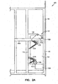
- Figures 1 and 2 illustrate an embodiment of a transport system that moves a visible and/or an infrared (IR) camera enclosed in an industrial housing along a rail. While the embodiment of Figures 1 and 2 show a transport system of the invention in connection with an IR camera; those of skill in the art will readily realize that the invention is not limited to an IR camera, but that embodiments of the transport system of Figures 1 and 2 could also transport other pieces of equipment as well. Additionally, while the embodiment of Figure 1 is discussed in connection with an industrial furnace, those of skill in the art will readily realize that the transport system of Figures 1 and 2 can be used in connection with other pieces of industrial equipment also.
- IR infrared
- the support and transport structure 100 of Figure 1 has a frame 105. Attached to the frame 105 is a first motion transport system.
- the first motion transport system is a pneumatic transport system that consists of a rail 110 and a trolley structure 115.
- the rail 110 is one that is manufactured by Tol-o-matic® of Hamel, Minnesota (www.tolomatic.com ).
- the frame 105 is attached to the outside of the wall of an industrial housing 140, and the pneumatic transport system is attached to the frame 105.
- the wall of the industrial housing 140 is an outside wall of a furnace.
- Positioned on top of the trolley structure 115 is an enclosure 120.
- the enclosure 120 contains a stepper motor 126 and a shaft 127.
- the stepper motor and shaft have wheels 128, 129 attached thereto respectively, and wheels 128, 129 are coupled via a belt, a chain, a gearing system or other means 130. ( See Figure 2 ).
- a control box 137 that houses a control processor and electrical and pneumatic controls. Also attached to the control box 137 is a reservoir 138 for the storage of pneumatic air.
- a second industrial housing 135 is connected to the end of shaft 127 opposite that of the wheel 129. In an embodiment, the industrial housing 135 encloses a camera, such as an IR camera.
- a second motion transport system that, like the first motion transport system, may be a pneumatic transport system. In the embodiment of Figure 1 , such a pneumatic transport system has a rail 150, a second trolley structure 156, and a door 154.
- the second trolley structure is attached to the door 154 with attachments 157 and tension springs 153 that attach the door 154 to the pneumatic transport system via a door trolley structure 156.
- the door trolley 156 in Figures 1 and 2 is depicted in generic form to indicate that several connecting mechanisms known in the art could be used to connect the door 154 to the trolley structure 156.
- the attachment 157 includes a triangular bracket 157a and a roller 158b to connect the bracket 157a to the trolley structure 156.
- the door covers an opening 160 in the industrial housing wall 140 ( Figure 2 ).
- the transport system 100 supports and transports the industrial housing 135 into and out of an industrial environment.
- the industrial environment is a furnace
- the industrial housing 135 encloses an IR camera.
- An exploded view of an embodiment of an industrial housing 135 and an IR camera is illustrated in Figure 3 .
- the housing 135 has a bottom plate 171, and encloses a camera 170.
- An opening 172 receives the camera lens (not shown in Figure 3 ) that is attached to the camera 170.
- the camera lens is enclosed and protected by a window 173 and lens housing 174 that is attached to the industrial housing.
- a coupling unit 175 attaches onto the housing wall, and serves to connect the housing 135 to the shaft 127.
- the industrial housing 135 is manufactured out of hardened stainless steel, and the window 173 is made out of sapphire.
- the lens attached to the camera may be a wide angle lens, a narrow angle lens, and/or a telescoping lens.
- the door 154 has been moved in the direction of arrow A.
- the movement of the door along arrow A occurs by activating the second pneumatic transport system, which moves door trolley 156 and the door 154 along rail 150, thereby exposing opening 160 in the industrial wall 140.
- attachments 157 A&B and tension springs 153 A&B secure the door 154 to the door trolley 156.
- the attachment 157 between door trolley 156 and the door 154 has compression springs 157C to ensure a tight seal between the door 154 and the wall 140 when the door trolley 156 is in the lowered position.
- Tension springs 153 A&B between door 154 and door trolley 156 is to ensure the door is held against the door trolley and away from the wall 140 when the door trolley is in the upper position.
- the compression spring force of attachments 157 A&B releases and tension springs 153 A&B pull door 154 toward door trolley 156 and away from the wall 140. This ensures that there is no interference between the door 154 and the wall 140 or other structure.
- both the door trolley 156 and door 154 move in the direction of arrow A.
- attachment 157A pushes the door 154 away from the door trolley 156 toward wall 140.
- the tension spring 153A first pulls the door 154 back away from the industrial wall 140 and then door trolley 156 and door 154 move together in the direction of arrow A.
- an adapter can be welded or otherwise coupled onto the wall of the industrial housing. The surface of the adapter that contacts the door 154 can then be machined to accurately mate with the door.
- Figure 2 further shows that enclosure 120, shaft 127, and housing 135 have been moved along rail 110 via the activation of the first pneumatic transport system.
- the housing 135 itself has been moved through opening 160 into the industrial housing 140.
- Figure 2 further illustrates that the industrial housing 135 has been rotated from a home position as illustrated in Figure 1 (as determined by the direction that the window 173 and lens housing 174 is pointed), to a deployed position as illustrated in Figure 2 .
- the industrial housing is attached to the shaft 127 by a mechanism that allows the industrial housing 135 to tilt when it is in the industrial housing 140.
- the transport structure 100 is connected to a processor housed in control box 137 that controls the functions of the transport system 100.
- a flowchart outlining an embodiment of the control process is illustrated in Figure 4 .
- the control process 400 at block 405 (a process control computer) transmits a signal to the camera 170 to determine the temperature of the camera. If the temperature of the camera is too high, for example because of a recent incursion into a furnace, the process control will not move the camera into the furnace.
- a timed loop is programmed into the processor logic to poll the temperature again, and see if the temperature is low enough to be inserted into the furnace.
- the insertion of the camera is on a timed and scheduled basis, and the system then waits for the next scheduled time to insert the camera into the furnace.
- an operator provides a command to the processor to move the camera into the furnace, and if insertion does not occur because the temperature of the camera is too high, the operator can wait before reissuing the command.
- image and rotation angle commands are transmitted from the camera to a programmable logic controller (PLC) housed in control box 137 (block 412).
- PLC programmable logic controller
- the image command readies the IR camera 170 for capturing images, and the rotation command is sent to the PLC which communicates with the stepper motor controller, housed in control box 137, which rotates the camera so that the window 173 and lens housing 174 will be pointed in the desired direction at 427.
- the PLC checks to see if the industrial housing 135, the enclosure 120, and the control box 137 have been successfully purged.
- a purge system 139 housed in control box 137, establishes a positive pressure in the enclosure 120, the control box 137, and the housing 135. This positive pressure keeps contaminants from leaking into these structures. If the Purge is OK, the PLC then checks in block 420 whether the camera 135 is out and the door 154 is closed. If the camera is out and the door 154 to the housing 140 is closed, the PLC checks in block 425 to see if the camera window 173 and lens housing 174 are located in the home position. If the camera is home, signals are then sent to the stepper motor at 427 so that the camera is rotated the desired number of degrees to the desired angle ( i . e . the deployed position).
- a variable representing the health or status of the PLC is set to zero and sent to the camera in block 430, and the camera communicates a PLC health error indication to the process computer.
- the processor sends a signal to energize a pneumatic valve which opens the door 154 that seals the housing 140.
- the processor checks to see if the door successfully opened. If the door did not open successfully, the PLC health status is set to zero at 430, and the PLC sends the information to the camera. If the door successfully opened, the first pneumatic transport system is energized at 447, and the housing 135 and camera 170 are moved through the housing wall 140. The processor then determines if the camera was moved into the housing successfully at 450. If it was not, the PLC status is once again set to zero. If the processor determines that the camera was moved into the furnace successfully, images are captured by the camera at 460.
- the camera then communicates with the process computer in block 405 and transfers the images. These images may be transmitted via wired or unwired means. Then, after a short time in the furnace at 465 (three seconds in one embodiment), the PLC sends a signal to the first pneumatic transport system at 470 to energize the valve again so that the housing and camera are removed from the furnace. The PLC checks to see if the camera was successfully removed from the furnace at 475. If it was, not, the PLC status is set to zero. If the camera was successfully removed from the furnace, the close door valve of the second pneumatic transport system is reenergized at 480, and the door 154 is closed. The PLC checks to see if the door was successfully closed (485), and if it was not, PLC status is set to zero.
- the processor status is set to zero and the system goes into a failsafe state. If instrument air is lost in the failsafe state, the pneumatic air in the reservoir 138 is used by the system to remove the camera from the furnace (if the camera is in the furnace wen the problem occurs), and to shut the door 154 (if once again the door is open when the problem occurs).
- This failsafe operation prevents the situation where the furnace door remains open because of a failure of some part of the system.
- an alternative power supply such as a battery or gas-powered generator, could be used to put the system into the failsafe mode.
Landscapes
- Physics & Mathematics (AREA)
- General Physics & Mathematics (AREA)
- Engineering & Computer Science (AREA)
- Automation & Control Theory (AREA)
- Waste-Gas Treatment And Other Accessory Devices For Furnaces (AREA)
- Testing Or Calibration Of Command Recording Devices (AREA)
- Studio Devices (AREA)
- Power-Operated Mechanisms For Wings (AREA)
Claims (9)
- Vorrichtung, die Folgendes umfasst:einen Rahmen (105);ein erstes Druckluftsystem (110, 115, 137), das an dem Rahmen befestigt ist; ein zweites Druckluftsystem (137, 150, 156), das an dem Rahmen befestigt ist;ein Industriegehäuse (135), das mit dem ersten Druckluftsystem verbunden ist;einen Motor (126), wobei der Motor mit dem ersten Druckluftsystem und dem Industriegehäuse verbunden ist;eine Welle (127), wobei die Welle den Motor mit dem Industriegehäuse verbindet;eine speicherprogrammierbare Steuerung (137), die mit dem ersten Druckluftsystem und dem zweiten Druckluftsystem gekoppelt ist, wobei die speicherprogrammierbare Steuerung in einem Steuerkasten (137) untergebracht ist;eine Ummantelung (120) zur Aufnahme des Motors;eine Tür (154), die mit dem zweiten Druckluftsystem verbunden ist;ein Spülsystem (139) zur Erzeugung eines Überdrucks in dem Steuerkasten, der Ummantelung, die den Motor aufnimmt und dem Industriegehäuse; undeinen industriellen Ausrüstungsgegenstand (140),wobei der Rahmen an dem industriellen Ausrüstungsgegenstand befestigt ist.
- Vorrichtung nach Anspruch 1, wobei die industrielle Ausrüstung einen Ofen (140) umfasst.
- Vorrichtung nach Anspruch 1 oder 2, die weiterhin eine Kamera (170) umfasst, die in dem Industriegehäuse (135) enthalten ist, wobei die Kamera eine Infrarotkamera mit einem Weitwinkelobjektiv (173) umfasst.
- Vorrichtung nach einem der vorhergehenden Ansprüche, die weiterhin Folgendes umfasst:ein zweites Laufwerk (156), das an dem zweiten Druckluftsystem (137, 150) befestigt ist; undein Stellglied (157), das das zweite Laufwerk mit der Tür (154) verbindet;wobei das zweite Druckluftsystem (137, 150, 156) bewirkt, dass sich die Tür in einer ersten Richtung (A) bewegt, und das Stellglied bewirkt, dass sich die Tür von der industriellen Ausrüstung (140) weg bewegt; und
wobei weiterhin das zweite Druckluftsystem bewirkt, dass sich die Tür in einer zweiten Richtung (B) bewegt, und das Stellglied bewirkt, dass sich die Tür zu der industriellen Ausrüstung bewegt. - Vorrichtung nach einem der vorhergehenden Ansprüche, wobei das Industriegehäuse (135) gehärteten rostfreien Stahl umfasst.
- Vorrichtung nach Anspruch 1,
wobei das erste Druckluftsystem eine erste Schiene (110) enthält und das zweite Druckluftsystem eine zweite Schiene (150) enthält, wobei der Rahmen, die erste Schiene und die zweite Schiene an dem industriellen Ausrüstungsgegenstand (140) befestigt sind;
wobei der Motor (126) verschiebbar mit der ersten Schiene gekoppelt ist; und
die Tür (154) verschiebbar mit der zweiten Schiene gekoppelt ist, wobei die Tür zum Bedecken einer Öffnung (160) an der industriellen Einrichtung bestimmt ist;
wobei die Vorrichtung weiterhin Folgendes umfasst:eine Infrarotkamera (170), die in dem Industriegehäuse positioniert ist;
wobei das erste Druckluftsystem weiterhin ein Mittel (115) zum Bewegen des Motors entlang der ersten Schiene enthält und das zweite Druckluftsystem weiterhin ein Mittel (156) zum Bewegen der Tür entlang der zweiten Schiene enthält; undeinen Prozessor (137), wobei der Prozessor mit dem Motor, der Tür, dem Mittel zum Bewegen des Motors entlang der ersten Schiene und dem Mittel zum Bewegen der Tür entlang der zweiten Schiene gekoppelt ist. - Vorrichtung nach Anspruch 6, wobei das Mittel (115) zum Bewegen des Motors entlang der ersten Schiene und das Mittel (156) zum Bewegen der Tür entlang der zweiten Schiene ein bewegliches Transportsystem umfassen.
- Vorrichtung nach Anspruch 6, wobei das Mittel (115) zum Bewegen des Motors entlang der ersten Schiene und das Mittel (156) zum Bewegen der Tür entlang der zweiten Schiene ein Druckluftsystem umfassen.
- Verfahren, das Folgendes umfasst:Ermitteln (410) einer Temperatur einer Kamera (170);Drehen (427) der Kamera in eine ausgebrachte Position;Anlegen (415) eines Innenüberdrucks an die Kamera;Öffnen (440) einer Tür (156), die eine Öffnung in einem Ofen bedeckt;Bewegen (447) der Kamera unter Verwendung eines Transportsystems (110, 115) in den Ofen;Aufnehmen (460) von Bildern mit der Kamera in dem Ofen;Entfernen (470) der Kamera aus dem Ofen;Übertragen (448) der Bilder auf einen Prozessor;Schließen (480) der Tür nach dem Entfernen der Kamera;Überprüfen (485), dass die Tür geschlossen ist;Erfassen (430) eines Fehlerzustands;Zurückziehen (470) der Kamera aus dem Ofen; und Schließen (480) der Tür.
Applications Claiming Priority (2)
| Application Number | Priority Date | Filing Date | Title |
|---|---|---|---|
| US11/322,528 US7641402B2 (en) | 2005-12-30 | 2005-12-30 | Transport system for monitoring industrial process |
| PCT/US2006/048348 WO2007078933A1 (en) | 2005-12-30 | 2006-12-19 | Transport system for monitoring industrial processes |
Publications (2)
| Publication Number | Publication Date |
|---|---|
| EP1969433A1 EP1969433A1 (de) | 2008-09-17 |
| EP1969433B1 true EP1969433B1 (de) | 2010-04-14 |
Family
ID=38042732
Family Applications (1)
| Application Number | Title | Priority Date | Filing Date |
|---|---|---|---|
| EP06845768A Ceased EP1969433B1 (de) | 2005-12-30 | 2006-12-19 | Transportsystem zur überwachung industrieller prozesse |
Country Status (6)
| Country | Link |
|---|---|
| US (3) | US7641402B2 (de) |
| EP (1) | EP1969433B1 (de) |
| JP (1) | JP4944900B2 (de) |
| CN (1) | CN101395546B (de) |
| DE (1) | DE602006013710D1 (de) |
| WO (1) | WO2007078933A1 (de) |
Families Citing this family (12)
| Publication number | Priority date | Publication date | Assignee | Title |
|---|---|---|---|---|
| US7641402B2 (en) * | 2005-12-30 | 2010-01-05 | Honeywell International Inc. | Transport system for monitoring industrial process |
| DE102007048684B4 (de) * | 2007-10-10 | 2010-09-09 | Polysius Ag | Laborsystem |
| US8023818B2 (en) * | 2008-07-24 | 2011-09-20 | Fluke Corporation | Articulating infrared window |
| US8199193B2 (en) * | 2008-10-30 | 2012-06-12 | Caskol, Llc | Video camera inspection system for roller hearth heat treating furnaces and the like |
| US9509923B2 (en) * | 2012-01-10 | 2016-11-29 | General Electric Company | Continuous infrared thermography monitoring and life management system for heat recovery steam generators |
| US9127891B2 (en) * | 2013-07-10 | 2015-09-08 | Honeywell International, Inc. | Furnace visualization |
| EP2887328B1 (de) * | 2013-12-19 | 2016-04-20 | Axis AB | Auf einer Schiene mit vorbestimmten Befestigungspunkten montierte Überwachungsvorrichtungen |
| EP3168819B1 (de) | 2015-11-16 | 2017-12-27 | Axis AB | Schutzglocke für überwachungskamerasystem |
| WO2018002683A1 (en) * | 2016-06-30 | 2018-01-04 | Centre De Pyrolyse Du Charbon De Marienau | Device for measuring a shape of a wall portion of an oven, such as a coke oven |
| CN107390596B (zh) * | 2017-08-30 | 2019-07-09 | 合肥福瞳光电科技有限公司 | 一种智能办公室门牌管理系统 |
| US11802732B2 (en) | 2021-02-26 | 2023-10-31 | Rtx Corporation | Systems and methods for vacuum furnace post-processing |
| CN116087221B (zh) * | 2023-03-02 | 2023-09-08 | 东北电力大学 | 一种基于计算机视觉的空冷器积灰状态检测装置及方法 |
Family Cites Families (17)
| Publication number | Priority date | Publication date | Assignee | Title |
|---|---|---|---|---|
| US3021386A (en) * | 1960-03-30 | 1962-02-13 | Gen Electric | Boiler port viewing system |
| US4131914A (en) * | 1975-09-23 | 1978-12-26 | Bricmont & Associates, Inc. | Method and apparatus for inspecting refractory lining in coke oven chambers and the like |
| FR2544540B1 (fr) * | 1983-04-13 | 1985-10-25 | Commissariat Energie Atomique | Machine d'examen d'un assemblage combustible de reacteur nucleaire |
| US4815757A (en) * | 1986-04-24 | 1989-03-28 | Hamilton Mark L | Rapid development surveillance vehicle and method |
| US4913458A (en) * | 1986-04-24 | 1990-04-03 | Hamilton Mark L | Surveillance vehicle control system |
| JP3175391B2 (ja) * | 1993-03-16 | 2001-06-11 | 株式会社日立製作所 | 遮蔽体を備えた格納容器内監視装置 |
| JP3042758B2 (ja) * | 1995-02-17 | 2000-05-22 | 川崎製鉄株式会社 | コークス炉炭化室の炉壁診断方法および装置 |
| JP2872166B2 (ja) * | 1996-11-29 | 1999-03-17 | 建一 今野 | 圧縮空気を利用したモニタカメラ搬送装置 |
| US5835806A (en) * | 1997-02-26 | 1998-11-10 | The United States Of America As Represented By The Secretary Of Agriculture | Passive self-contained camera protection and method for fire documentation |
| US6229563B1 (en) * | 1998-07-14 | 2001-05-08 | Fosbel International Limited | Camera insertion into a furnace |
| JP2000180584A (ja) * | 1998-12-21 | 2000-06-30 | Hitachi Ltd | 監視装置及び監視システム |
| JP2000295502A (ja) * | 1999-04-06 | 2000-10-20 | Asahi Glass Co Ltd | 炉内観察装置 |
| JP3770073B2 (ja) * | 2000-10-30 | 2006-04-26 | 株式会社日立製作所 | 遠隔移動ロボット |
| DE60235963D1 (de) | 2001-02-16 | 2010-05-27 | Toyoda Automatic Loom Works | Kamerahebevorrichtung und lasthandhabungstragvorrichtung eines hubwagens und hubwagen |
| KR100467747B1 (ko) * | 2001-09-01 | 2005-01-26 | 주식회사 영국전자 | 로 내부 감시를 위한 비젼튜브의 자동 추출장치 |
| JP3875659B2 (ja) | 2003-07-25 | 2007-01-31 | 株式会社東芝 | カメラ装置及びロボット装置 |
| US7641402B2 (en) * | 2005-12-30 | 2010-01-05 | Honeywell International Inc. | Transport system for monitoring industrial process |
-
2005
- 2005-12-30 US US11/322,528 patent/US7641402B2/en not_active Expired - Fee Related
-
2006
- 2006-12-19 EP EP06845768A patent/EP1969433B1/de not_active Ceased
- 2006-12-19 DE DE602006013710T patent/DE602006013710D1/de active Active
- 2006-12-19 JP JP2008548605A patent/JP4944900B2/ja not_active Expired - Fee Related
- 2006-12-19 WO PCT/US2006/048348 patent/WO2007078933A1/en not_active Ceased
- 2006-12-19 CN CN2006800536084A patent/CN101395546B/zh not_active Expired - Fee Related
-
2008
- 2008-08-04 US US12/185,655 patent/US8562227B2/en not_active Expired - Fee Related
-
2009
- 2009-10-08 US US12/576,072 patent/US7832946B2/en not_active Expired - Fee Related
Also Published As
| Publication number | Publication date |
|---|---|
| EP1969433A1 (de) | 2008-09-17 |
| DE602006013710D1 (de) | 2010-05-27 |
| US20080291270A1 (en) | 2008-11-27 |
| US8562227B2 (en) | 2013-10-22 |
| JP2009522548A (ja) | 2009-06-11 |
| US7641402B2 (en) | 2010-01-05 |
| CN101395546A (zh) | 2009-03-25 |
| WO2007078933A1 (en) | 2007-07-12 |
| US7832946B2 (en) | 2010-11-16 |
| CN101395546B (zh) | 2011-08-10 |
| US20070154205A1 (en) | 2007-07-05 |
| US20100021154A1 (en) | 2010-01-28 |
| JP4944900B2 (ja) | 2012-06-06 |
Similar Documents
| Publication | Publication Date | Title |
|---|---|---|
| US8562227B2 (en) | Transport system for monitoring industrial processes | |
| CN106494847A (zh) | 皮带运输机巡检系统 | |
| CN109187063A (zh) | 机器人避障功能的检测装置和检测方法 | |
| JP4157466B2 (ja) | 弁漏洩検知システム | |
| KR101663653B1 (ko) | 전력선통신이 가능하고 환경센서군 및 Wi-Fi모듈이 탑재된 Gateway를 이용한 공사현장의 안전과 시설물 관리장치 | |
| CN213616681U (zh) | 电缆沟巡检机器人系统 | |
| JP2006120820A (ja) | 薄型基板処理装置及び薄型基板搬送装置 | |
| CN2692662Y (zh) | 烟雾探测器 | |
| CN113119061B (zh) | 一种巡检机器人及其控制方法 | |
| CN102686369B (zh) | 用于诊断具有活动件的装置的设施 | |
| JP2003331369A (ja) | ガス検知装置およびガス検知システム | |
| JP6316739B2 (ja) | バルブアクチュエータ | |
| CN119125619A (zh) | 一种基于人工智能的电子产品性能测试装置及其分析系统 | |
| KR100228137B1 (ko) | 로봇을 이용한 교량의 케이블 검사 시스템 | |
| CN215262366U (zh) | 一种二维力检测机构和机器人 | |
| JPH08240069A (ja) | 電源装置用扉の自動開閉装置 | |
| CN115962372A (zh) | 一种悬挂巡查的管道侦查机器人及悬挂巡查方法 | |
| CN113376065A (zh) | 玻璃颗粒检查设备 | |
| CN215886870U (zh) | 具有监控功能的门禁系统 | |
| CN118739974B (zh) | 一种非接触式电机温度自动监控系统及方法 | |
| CN114310937A (zh) | 一种能够一体化监测的防爆巡检机器人 | |
| JPS59138996A (ja) | ホツトセル内の整備作業方法 | |
| CN215894441U (zh) | 一种具有自动开盖功能的分析仪 | |
| CN119602477A (zh) | 一种基于北斗通信的输电线路状态监测系统 | |
| CN212228462U (zh) | 一种封闭化验自动粮食扦样机 |
Legal Events
| Date | Code | Title | Description |
|---|---|---|---|
| PUAI | Public reference made under article 153(3) epc to a published international application that has entered the european phase |
Free format text: ORIGINAL CODE: 0009012 |
|
| 17P | Request for examination filed |
Effective date: 20080627 |
|
| AK | Designated contracting states |
Kind code of ref document: A1 Designated state(s): DE FR GB |
|
| RIN1 | Information on inventor provided before grant (corrected) |
Inventor name: ALVAREZ, MANUEL, S. Inventor name: LANE, CHARLES, E. III Inventor name: SHEARD, JUSTIN, M. Inventor name: HAIN, LARRY, A. Inventor name: VOLNA, WILLIAM, M. Inventor name: KOCANDA, ROBERT, F. Inventor name: SCHMIDT, ROGER, N. |
|
| RIN1 | Information on inventor provided before grant (corrected) |
Inventor name: SCHMIDT, ROGER, N. Inventor name: LANE, CHARLES, E. III Inventor name: SHEARD, JUSTIN, M. Inventor name: VOLNA, WILLIAM, M. Inventor name: HAIN, LARRY, A. Inventor name: KOCANDA, ROBERT, F. Inventor name: ALVAREZ, MANUEL, S. |
|
| 17Q | First examination report despatched |
Effective date: 20081106 |
|
| DAX | Request for extension of the european patent (deleted) | ||
| RBV | Designated contracting states (corrected) |
Designated state(s): DE FR GB |
|
| GRAP | Despatch of communication of intention to grant a patent |
Free format text: ORIGINAL CODE: EPIDOSNIGR1 |
|
| GRAS | Grant fee paid |
Free format text: ORIGINAL CODE: EPIDOSNIGR3 |
|
| GRAA | (expected) grant |
Free format text: ORIGINAL CODE: 0009210 |
|
| AK | Designated contracting states |
Kind code of ref document: B1 Designated state(s): DE FR GB |
|
| REG | Reference to a national code |
Ref country code: GB Ref legal event code: FG4D |
|
| REF | Corresponds to: |
Ref document number: 602006013710 Country of ref document: DE Date of ref document: 20100527 Kind code of ref document: P |
|
| PLBE | No opposition filed within time limit |
Free format text: ORIGINAL CODE: 0009261 |
|
| STAA | Information on the status of an ep patent application or granted ep patent |
Free format text: STATUS: NO OPPOSITION FILED WITHIN TIME LIMIT |
|
| 26N | No opposition filed |
Effective date: 20110117 |
|
| REG | Reference to a national code |
Ref country code: FR Ref legal event code: PLFP Year of fee payment: 10 |
|
| REG | Reference to a national code |
Ref country code: FR Ref legal event code: PLFP Year of fee payment: 11 |
|
| REG | Reference to a national code |
Ref country code: FR Ref legal event code: PLFP Year of fee payment: 12 |
|
| PGFP | Annual fee paid to national office [announced via postgrant information from national office to epo] |
Ref country code: FR Payment date: 20171229 Year of fee payment: 12 |
|
| PGFP | Annual fee paid to national office [announced via postgrant information from national office to epo] |
Ref country code: GB Payment date: 20171228 Year of fee payment: 12 |
|
| PGFP | Annual fee paid to national office [announced via postgrant information from national office to epo] |
Ref country code: DE Payment date: 20180228 Year of fee payment: 12 |
|
| REG | Reference to a national code |
Ref country code: DE Ref legal event code: R119 Ref document number: 602006013710 Country of ref document: DE |
|
| GBPC | Gb: european patent ceased through non-payment of renewal fee |
Effective date: 20181219 |
|
| PG25 | Lapsed in a contracting state [announced via postgrant information from national office to epo] |
Ref country code: DE Free format text: LAPSE BECAUSE OF NON-PAYMENT OF DUE FEES Effective date: 20190702 Ref country code: FR Free format text: LAPSE BECAUSE OF NON-PAYMENT OF DUE FEES Effective date: 20181231 |
|
| PG25 | Lapsed in a contracting state [announced via postgrant information from national office to epo] |
Ref country code: GB Free format text: LAPSE BECAUSE OF NON-PAYMENT OF DUE FEES Effective date: 20181219 |