EP1967302A1 - Automatic pouring method and device - Google Patents
Automatic pouring method and device Download PDFInfo
- Publication number
- EP1967302A1 EP1967302A1 EP08000222A EP08000222A EP1967302A1 EP 1967302 A1 EP1967302 A1 EP 1967302A1 EP 08000222 A EP08000222 A EP 08000222A EP 08000222 A EP08000222 A EP 08000222A EP 1967302 A1 EP1967302 A1 EP 1967302A1
- Authority
- EP
- European Patent Office
- Prior art keywords
- ladle
- pouring
- axis
- rotation
- molten metal
- Prior art date
- Legal status (The legal status is an assumption and is not a legal conclusion. Google has not performed a legal analysis and makes no representation as to the accuracy of the status listed.)
- Granted
Links
- 238000000034 method Methods 0.000 title claims abstract description 30
- 239000002184 metal Substances 0.000 claims abstract description 102
- 238000000465 moulding Methods 0.000 claims abstract description 34
- 230000003287 optical effect Effects 0.000 claims description 3
- 230000007547 defect Effects 0.000 abstract description 3
- 239000004576 sand Substances 0.000 abstract description 3
- 230000005484 gravity Effects 0.000 description 10
- 238000010079 rubber tapping Methods 0.000 description 6
- 238000013459 approach Methods 0.000 description 5
- 238000004519 manufacturing process Methods 0.000 description 4
- 238000001514 detection method Methods 0.000 description 3
- 238000002360 preparation method Methods 0.000 description 3
- 230000001360 synchronised effect Effects 0.000 description 3
- 238000005266 casting Methods 0.000 description 2
- 230000003028 elevating effect Effects 0.000 description 2
- 230000005540 biological transmission Effects 0.000 description 1
- 230000001143 conditioned effect Effects 0.000 description 1
- 238000010586 diagram Methods 0.000 description 1
- 230000000694 effects Effects 0.000 description 1
- 238000005259 measurement Methods 0.000 description 1
- 230000002093 peripheral effect Effects 0.000 description 1
- 238000004904 shortening Methods 0.000 description 1
- 239000000725 suspension Substances 0.000 description 1
Images


Classifications
-
- B—PERFORMING OPERATIONS; TRANSPORTING
- B22—CASTING; POWDER METALLURGY
- B22D—CASTING OF METALS; CASTING OF OTHER SUBSTANCES BY THE SAME PROCESSES OR DEVICES
- B22D39/00—Equipment for supplying molten metal in rations
-
- B—PERFORMING OPERATIONS; TRANSPORTING
- B22—CASTING; POWDER METALLURGY
- B22D—CASTING OF METALS; CASTING OF OTHER SUBSTANCES BY THE SAME PROCESSES OR DEVICES
- B22D37/00—Controlling or regulating the pouring of molten metal from a casting melt-holding vessel
-
- B—PERFORMING OPERATIONS; TRANSPORTING
- B22—CASTING; POWDER METALLURGY
- B22D—CASTING OF METALS; CASTING OF OTHER SUBSTANCES BY THE SAME PROCESSES OR DEVICES
- B22D41/00—Casting melt-holding vessels, e.g. ladles, tundishes, cups or the like
- B22D41/04—Casting melt-holding vessels, e.g. ladles, tundishes, cups or the like tiltable
-
- B—PERFORMING OPERATIONS; TRANSPORTING
- B22—CASTING; POWDER METALLURGY
- B22D—CASTING OF METALS; CASTING OF OTHER SUBSTANCES BY THE SAME PROCESSES OR DEVICES
- B22D41/00—Casting melt-holding vessels, e.g. ladles, tundishes, cups or the like
- B22D41/06—Equipment for tilting
-
- B—PERFORMING OPERATIONS; TRANSPORTING
- B66—HOISTING; LIFTING; HAULING
- B66C—CRANES; LOAD-ENGAGING ELEMENTS OR DEVICES FOR CRANES, CAPSTANS, WINCHES, OR TACKLES
- B66C23/00—Cranes comprising essentially a beam, boom, or triangular structure acting as a cantilever and mounted for translatory of swinging movements in vertical or horizontal planes or a combination of such movements, e.g. jib-cranes, derricks, tower cranes
- B66C23/18—Cranes comprising essentially a beam, boom, or triangular structure acting as a cantilever and mounted for translatory of swinging movements in vertical or horizontal planes or a combination of such movements, e.g. jib-cranes, derricks, tower cranes specially adapted for use in particular purposes
- B66C23/20—Cranes comprising essentially a beam, boom, or triangular structure acting as a cantilever and mounted for translatory of swinging movements in vertical or horizontal planes or a combination of such movements, e.g. jib-cranes, derricks, tower cranes specially adapted for use in particular purposes with supporting couples provided by walls of buildings or like structures
- B66C23/201—Cranes comprising essentially a beam, boom, or triangular structure acting as a cantilever and mounted for translatory of swinging movements in vertical or horizontal planes or a combination of such movements, e.g. jib-cranes, derricks, tower cranes specially adapted for use in particular purposes with supporting couples provided by walls of buildings or like structures with supporting couples provided from above, e.g. by ceilings of buildings
Definitions
- the present invention relates to an automatic pouring method and an automatic pouring device. Specifically, it relates to an automatic pouring method that can make a pouring device simple and compact, and an automatic pouring device that can carries out that pouring method.
- Prior-art Patent 1 discloses controlling the tilt of a ladle by the two rotating means connected to the ladle to pour molten metal from the ladle to a mold, as shown in Figure 2 of it.
- the first rotating means is an actuator for vertically moving a tilting shaft disposed near the pouring point of the ladle. By that vertical movement, the ladle is rotated about the center of gravity S of the molten metal (the center acts as a virtual axis of rotation).
- the second rotating means is a suspending wire connected to the ladle at the point D for rotating the ladle about the point K, which is the axis of rotation of the tilting shaft.
- the rotating rate at the point S can be made zero by applying a high rotating rate to the point K and applying a low rotating rate to the point D (see Figure 3 ).
- the rotating rate at the point S can be made zero.
- Prior-art Patent 1 also discloses moving a structure laterally that supports the first and second rotating means so that the pouring point of the ladle approaches the pouring cup of the mold, as shown in Figure 4 .
- the first and second rotating means are controlled manually or using a program.
- the pouring device of prior-art Patent 1 requires a large-scale device (a tower), and it tends to cause problems due to the pouring that is carried out from a higher level, namely, an unstable pouring with turbulent flows, defects of sand and/or gas inclusion, and the like.
- Prior-art Patent 2 discloses a device for pouring molten metal in a mold by tilting a ladle about the axis of rotation A of a tilting shaft and by moving the ladle along an X-axis (the directions in wich the ladle moves toward and away from the mold) and a Z-axis (the vertical directions) to always keep a theoretical (virtual) pouring point, which is near the pouring point, in the lowest possible position relative to the mold.
- the ladle is moved along the X-axis, a Y-axis (the directions along the molding line), and the Z-axis by a longitudinal cart, a lateral cart, and a suspension wire, respectively, and is tilted by a drive motor.
- the pouring device of this prior-art Patent 2 also requires a large tower, it tends to cause problems in that it becomes large, to consume great energy, and to be at a high cost. Further, if a tall tower is used, its center of gravity will be located at a high level, causing another problem in that great vibrations generate due to the movement of the pouring device, making pouring accuracy worse. In addition, the tall tower causes another problem in that it limits the transportation path and hence the transportation means, resulting in a longer time to change the ladle. The tall tower causes a further problem in that it blocks its peripheral sight, making it difficult to see if the site is safe under the dangerous working environment where the molten metal is handled.
- Prior-art Patent 3 discloses pouring molten metal from a tiltable ladle into a mold by tiltably supporting the ladle by a tilting shaft at the tilting center (this center is supposed to be substantially positioned at the center of gravity of the ladle) and by rotating the tilting shaft by a drive motor about the tilting center, and by simultaneously moving the tilting shaft so that its axis (the tilting center) moves along the circular locus about the pouring point of the ladle so as to keep the pouring point (or a virtual pouring point near that pouring point) in one constant position relative to the mold (i.e., the horizontal distance 1 and the vertical distance h of the pouring point from the pouring cup of the mold are kept).
- the ladle is supported by a supporting element lying under it.
- Moving the tilting shaft along the circular locus about the pouring point when the tilting shaft is rotated (i.e., the ladle is tilted) by the motor is achieved by moving the supporting element along a Y-axis (the directions in which the ladle moves toward and away from the mold) and a Z-axis (the vertical directions).
- the movement of the ladle along the Y-axis is achieved by a cart, and the movement of the ladle along the Z-axis is achieved by a lifter.
- the movement of the ladle along the Y-axis and the Z-axis to be generated when it is tilted is controlled by a controller according to a control flow.
- the controller also controls the rotating rate of the tilting shaft (i.e., the tilting rate of the ladle) to control the varying rate of the surface of the molten metal.
- a virtual pouring point center system to rotate the tilting shaft about the virtual pouring point to keep the virtual pouring point in a constant position relative to the pouring cup of the mold, as in prior-art Patent 3.
- Prior-art Patent 4 relates to the improvement of the patent of prior-art Patent 3.
- the molten metal may be poured outside the pouring cup of the mold during the pouring if the rate and quantity of the metal flow vary due to the tilt of the ladle.
- prior-art Patent 4 the tilting shaft is moved along a locus that slightly shifts from the circular locus of the tilting shaft about the virtual pouring point of prior-art Patent 3.
- the movement of the supporting element for the ladle along the Y-axis is achieved by a cart, and its movement along the Z-axis is achieved by an actuator.
- the tilt of the ladle about the tilting center is achieved by a sector gear secured to the ladle and a means for rotating the sector gear.
- the movement of the ladle in the Z-axis is carried out by an actuator, a chain, or a lifter, or the combination of them. Accordingly, the pouring device still have a problem that they are tall.
- the present invention has been conceived to solve the above problems. It aims to provide an automatic pouring method that can make the pouring device simple and compact by improving the conventional pouring devices, without using a tower or any driving device for vertical moving the ladle such as an actuator or the like and provide an automatic pouring device that can carries out the pouring method of the present invention. Further, the present invention also aims to provide an automatic pouring device that gives a high precision pouring and easy checking on the safety, and that enables one to easily change the ladle.
- the automatic pouring method of the present invention is a method using a ladle to be tilted for pouring molten metal into a pouring cup of at least one flaskless or tight-flask mold in at least one pouring device movable along an X-axis parallel to a molding line in which the at least one mold is transferred, wherein the ladle is movable along a Y-axis perpendicular to the molding line in a horizontal plane, and the pouring is carried out just by moving the ladle along the X-axis and the Y-axis and by tilting the ladle about a first axis of rotation, without vertically moving the ladle.
- the automatic pouring device of the present invention is one for pouring molten metal from a tiltable ladle into at least one mold in a molding line, comprising: a lower cart movable along an X-axis parallel to the molding line; an upper cart mounted on the lower cart for laterally moving along a Y-axis perpendicular the molding line in a horizontal plane; a fixed frame fixedly mounted on the upper cart; a first tilting means for tilting the ladle about a first axis of rotation on the fixed frame; and an electric control unit provided with a program that just controls the movement of the ladle along the X-axis and the Y-axis and the tilt of the ladle about the first axis of rotation, without vertically moving the ladle.
- the automatic pouring method of the present invention since without using any drive device for vertically moving the ladle, it moves relative to the mold along the Y-axis perpendicular to the molding line in a horizontal plane and tilts about the first axis of rotation, and since the pouring is carried out by moving the ladle along the X-axis and the Y-axis and tilting it about the first axis of rotation, the problems such as the unstable pouring, the sand inclusion, and the gaseous defects, are eliminated, and the good pouring is carried out with the ladle being positioned at a low level.
- the automatic pouring device of the present invention since the drive device for vertically moving the ladle is not used, advantageously the pouring device will be simple and compact. Further, since the center of gravity of the pouring device can be lowered, the vibrations caused by its movement is reduced, and the pouring accuracy is improved. Additionally, since any elevating device such as a tower is not used, the transportation and the replacement of the ladle is easy, and the working efficiency is improved. In addition, eliminating any elevating device such as a tower gives a good sight in the site and enables anyone to check the safety under the dangerous environment where the molten metal is handled. Additionally, according to the device of the present invention, the electric control unit controls the servomotors for moving and tilting the ladle during the pouring. Accordingly, the invention will be appropriately carried out for low volume production of a wide variety of products of casts just by modifying the program for the positions of parameters of the poured weights of the molten metal, the pouring cups, etc.
- the ladle can also be tilted about a second axis of rotation that is located closer to the center of gravity of the ladle than is the first axis of rotation, the freedom of the ladle is increased, allowing the pouring device to work for various pouring.
- the first axis of rotation may be used for tilting the ladle at least for a period from the starting of the pouring to the time just before the stopping of the pouring.
- the second axis of rotation may be used at least for tilting back the ladle when the pouring is stopped.
- the second axis of rotation may be located near the center of gravity of the ladle so that it is tilted back about the axis near its center of gravity.
- the stopping of the pouring is quickly carried out, greatly improving the pouring accuracy. If the ladle is tilt back about the first axis of rotation, the molten metal moves by a great distance about that axis, causing the surface of the molten metal to vibrate, thereby delaying the completion of the pouring and worsening the pouring accuracy.
- the ladle is tilted about the first axis of rotation and the second axes of rotation, which differs from the first one, and since the tilt by the first axis of rotation is the tilt about a point at the tip of the ladle for pouring and the tilt by the second axis of rotation is the tilt back of the ladle about a point near the center of gravity of the ladle for stopping the pouring, the pouring is quickly stopped, and the pouring accuracy is greatly improved.
- the position along the Y-axis perpendicular to the molding line in a horizontal plane, and the tilt angles about the first and second axes of rotation, of the ladle can be conditionally controlled at least during the pouring, for the flow line of the molten metal that varies depending on the properties of the molten metal and the shape of the ladle.
- the present invention can quickly work for the change in the pouring weight, the change in the pouring rate, and the change in the flow line, caused by the variation of the tilt angle or angles.
- the present invention can quickly work for the change in the position the pouring cup.
- the control of the tilt and the control of the movement along the X-axis and the Y-axis, of the ladle can be simultaneously carried out at least for a period from the starting to the stopping of the pouring.
- said virtual pouring point center system the teaching playback system, which will be explained below, and the synchronous pouring system, which will also be explained below, can be used.
- the teaching playback system can be used to utilize the technique of the skilled worker.
- the skill worker actually pours molten metal from the ladle into one or a few molds, and the relation between the position along the Y-axis, the tilt angles of the shafts (the axes of rotation), the pouring rate, and the time, for that pouring by the worker is stored as a program in the electric control unit. If the product to be cast is changed, a program for that casting is then similarly stored.
- the teaching playback system is the system where one of the stored programs is selected or changed for use for a product to be actually cast.
- the optimum pouring can be immediately achieved for low volume production of a wide variety of products.
- the inventors have experienced many times that the pouring accuracy was low when this teaching playback system was not used, but just the mathematical principle computing system was used, since the shape of the ladle or the shape of the cavity of the mold differs.
- the synchronous pouring system can be used in the present invention to establish the pouring by a single pouring device for the molding line that travels at a high speed.
- the synchronous pouring system is a method of continuing the pouring even when the mold is traveling at the starting of the pouring or during the pouring.
- scaling the poured molten metal is achieved by always measuring the total weight of the lower cart or the ladle, by inputting the signal on the measured weight to the electric control unit, and by calculating the weight of the molten metal remaining in the ladle and the weight of the poured molten metal. When the weight of the poured molten metal reaches the predetermined weight, the pouring is ended (the weight-feedback system).
- the automatic pouring device of the present invention is an automatic pouring device to pour molten metal from a ladle to one or more tight-flask or flaskless molds that travel along a molding line.
- the automatic pouring device includes a lower cart that travels along the molding line; an upper cart that travels on the lower cart in forward and backward directions that are perpendicular to the molding line, a frame uprightly and fixedly mounted on the upper cart, a first tilting means for tilting the ladle about a first axis of rotation, and an electric control unit provided with a program to control the movement of the ladle in X and Y directions and control the tilt of the ladle about the first axis of rotation.
- the pouring method and device of the present invention can be applied to either a tight-flask mold or a flaskless mold.
- the wording "at least one pouring device” is used for the pouring method of the present invention, because plural pouring devices may be used according to the molding line.
- the wording "a ladle that can pour molten metal in the pouring cup of the mold by tilting" denotes that the present invention is not related to a stopper-type pouring ladle or a pressurized pouring ladle, but related to a ladle that has a center of rotation.
- the shape of the cross section of the ladle of the invention is, for instance, a sector or a rectangle.
- the term "automatic pouring” denotes automatically doing at least some operation that is conventionally manually done by an operator or operators.
- the ladle In the “automatic pouring,” the ladle is held, located in position, and tilted; the position in which the molten metal flows out of the ladle and the weight of the poured molten metal are monitored and then controlled by adjusting the position and the tilt angle of the ladle; and the ladle is refilled with molten metal when the molten metal in it is used.
- the term “the tilt angle about the first axis of rotation” denotes a relative angle with respect to the tilting frame of the ladle 2. Further, the term “the tilt angle about the second axis of rotation” denotes a relative angle of the tilting frame S with respect to the fixing frame F.
- the ladle of the present invention may be exchanged by a transportation means such as a hoist crane, a forklift, or the like. Further, it may be automatically and quickly changed by attaching drive rollers to a ladle-supporting frame and by driving the drive rollers together with other drive rollers attached to a fixed side. Since the pouring device of the invention has no tall tower, there is nothing to hinder the transfer path of the ladle when it is changed, and thus the transportation means and the transfer path are not limited. This allows the ladle that is to be changed after it has completed the pouring to be promptly exchanged for another ladle, by using a hoist crane, a forklift, or any other transfer means that moves perpendicularly to this ladle.
- a transportation means such as a hoist crane, a forklift, or the like.
- a first tilting means for tilting the ladle on the fixed frame about a first axis of rotation comprises, for example, a sector frame, for supporting the ladle, pivotably mounted on a tilting shaft having the first axis of rotation; a sector gear disposed around the periphery of the sector frame for tilting the sector frame, and a servomotor for driving the sector gear.
- a sector gear disposed around the periphery of the sector frame for tilting the sector frame, and a servomotor for driving the sector gear.
- a second tilting means for further tilting the ladle about a second axis of rotation comprises, for example, a tilting shaft having a second axis of rotation and passing through a fixed frame, which is in turn uprightly mounted on an upper cart; a servomotor as a drive means, coupled to the tilting shaft; and a tilting frame pivotally mounted on the tilting shaft at the other side, i.e., opposite the side to which the servomotor is coupled.
- the tilting frame is tilted about the second axis of rotation by the servomotor. Further, the tilting frame is pivotally mounted on the sector frame.
- the ladle can be titled by the tilting frame about the second axis of rotation, which differs from the first axis of rotation.
- the ladle can be tilted by the sector frame about the first axis of rotation.
- the means for supporting the ladle is a part mounted on a side surface of the sector frame for supporting the ladle, and the shape of the part differs depending on the shape of the ladle and the method of changing the ladle.
- the sector frame is a frame that is pivotably mounted on the tilting shaft having the first axis of rotation, and that directly supports the ladle on it.
- the sector frame is formed with a sector gear at the circular edge. The center of the sector gear coincides with the first axis of rotation.
- the sector frame is arranged to be driven to rotate about the first axis of rotation by a drive motor connected to the sector gear.
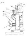
- Figures 1-4 show the first embodiment of the present invention.
- This embodiment is an example where molten metal is poured from a ladle in molds arranged on a molding line.
- the embodiment uses an X-axis (extending perpendicularly to the sheet of Figure 1 ), a Y-axis (extending in the rightward and leftward directions in the sheet of Figure 1 ), a first axis of rotation A (positioned near the tip of the pouring mouth of the ladle in this example), and a second axis of rotation B (in this example positioned near the center of gravity of the ladle).
- molds 1 are arranged in line with the molding line L and move intermittently.
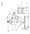
- a ladle 2 pours molten metal in these molds 1.
- the automatic pouring device 3 comprises a lower cart 4 movable via wheels 4b along a pair of rails 4a disposed alongside the molding line L (X-axis), an upper cart 5 movable via front and rear wheels 5a, 5a on the lower cart 4 in a horizontal direction (Y-axis) perpendicular to the molding line L, a frame F uprightly and fixedly mounted on the upper cart 5, a tilting frame S pivotably supported by this fixed frame F, and a supporting means pivotably supported by the tilting frame S for supporting the ladle 2.
- the movement of the lower cart 4 in the forward and backward directions (X-axis), the movement of the upper cart 5 in the lateral (Y-axis) direction, the tilt of the tiling frame S, and the tilt of the ladle 2, are all servo-driven by four respective servomotors, namely, a servomotor M5 for the forward and backward movement, a servomotor M4 for the lateral movement, a tilting servomotor MS for the tilting frame, and a tilting servomotor M2 for the ladle.
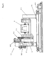
- the ladle 2 Via a sector-shaped sector frame G1 pivotably mounted on a tilting frame S, acting as a support means for the ladle 2; an L-shaped arm 7 disposed at a side surface of the sector frame G1, and a sector gear G2 engaging with a drive gear 6 of the servomotor M2, the ladle 2 is placed on a horizontal part 7a of the L-shaped arm 7 and is arranged to be tilted together with the sector frame G1 and the arm 7 about the first axis of rotation A. Further, the arm 7 allows a wheel 8, pivotably mounted on the bottom of the arm, to be tiltably supported by a liner 9 disposed on the side surface of the tilting frame S.
- This liner 9 is disposed in at least a range within which the sector frame G1 tilts.
- a liner 10 ( Figure 4 ) is also disposed on a back surface of the tilting frame S.
- the liner 10 is disposed in at least a range within which the tilting frame S tilts.
- the tilting frame S is supported by a wheel 11, which is in turn pivotably supported by the fixed frame F.
- the tilting frame S, which is pivotably supported by the fixed frame F, is arranged so that it is tilted by the drive servomotor MS about the second axis of rotation B.
- the ladle 2 is tilted not only about the first axis of rotation A, but also about the second axis of rotation B, which differs from the first axis of rotation A.
- the tilt angles of it about both the first and second axes A and B, and the position of it along the Y-axis are optimally adjusted.
- the electric control unit includes a program to control the servomotors in relation to the movement of the ladle in the X-and Y-directions and the tilt of it about the first and second axes. This program is called thereby controlling the servomotors so that the ladle pours the molten metal as programmed.
- a measuring means for measuring the weight of the poured molten metal continuously measures the total weight of the upper cart 5 with the load cell (not shown) and sends and inputs a signal on the measurements to the electric control unit to calculate the weight of the molten metal remaining in the ladle and the weight of the poured molten metal. The measuring means then judges that the predetermined weight of the molten metal has been poured when the calculated weight of the poured molten metal reaches that predetermined weight. The measuring means then instructs that pouring be stopped by employing a measured-weight feedback system.
- the weight of the poured molten metal may be alternatively measured by continuously scaling the total weight of the ladle 2 by a load cell, which is a measuring means to control the weight of molten metal to be poured.
- the program may employ a teaching playback system of an optimum pouring program and employ an optimum alignment for the tip of the ladle using the virtual pouring point center system where the axis of rotation of the pouring point is not fixed.
- the temperature and quality of the molten metal, the tilt angle of the ladle, and the shape, etc., of the ladle change, during the pouring the flow line of the molten metal changes.
- a study-and-feedback system may also be applied to carry out the optimum pouring in which these factors of the changes are continuously studied and fed back.
- Figure 6 shows an example of the automatic pouring operation of the automatic pouring device shown in Figures 1-4 .
- Figure 6(a) corresponds to Figure 1 and shows the original position, i.e., the starting position, of the automatic pouring device 3 for the automatic pouring.
- Figure 6(b) shows the step of pouring preparation.
- Figure 6(c) shows the step of pouring start.
- Figure 6(d) shows the step of pouring stop.
- Figure 6(e) shows the step of restarting pouring after the pouring is once stopped.
- Figure 6(f) shows the step of tapping all molten metal from the ladle. The step of tapping the molten metal is not always carried out on the mold.
- the upper cart 5 is positioned in the retraction (back) end of its passage, away from a mold 1.
- the tilting frame S is kept horizontal (i.e., the tilt angle of it is 0 degree). Accordingly, the bottom of the tilting frame S is now horizontal.
- the ladle 2 is also kept horizontal (the tilt angle of it is 0 degree). Accordingly, the surface of the molten metal in the ladle 2 is horizontal. Since the lower cart 4 can move alongside the X-axis, the pouring device 3 can move to the places where the molds to be poured with molten metal stand.
- the pouring is ready to start, with the ladle 2 fully refilled with molten metal.
- the upper cart 5 moves to the forward distal end of its passage, near the mold 1, to approach it.
- the tilting frame S is tilted from the horizontal position (where the tilt angle is zero) by, for example, 10 degrees.
- the ladle 2 is kept horizontal (the tilt angle of it is 0 degree).
- tilt angle is used in this meaning.
- Figure 6(c) shows the step of pouring start.
- the pouring begins.
- the upper cart 5 approaches the mold 1 and is held at the distal end.
- the tilt angle of the tilting frame S is kept at ten degrees.
- the ladle 2 is tilted from zero to five degrees. This rate of changing the tilt angle is changed by the program.
- Figure 6(d) shows the step of pouring stop, i.e., pouring end.
- the upper cart 5 is held at the distal end near the mold 1.
- the tilting frame S is tilted back so that its tilt angle is gradually changed from 10 degrees to 5 degrees. During this tilting back the tilt angle of the ladle is kept at 5 degrees.
- the measured-weight feedback system where the amount of the poured molten metal is measured, and then the pouring is finished if the measured amount becomes a predetermined one
- other systems may be used.
- an optical controlling system where the surface level of molten metal in a pouring cup is monitored by a camera, a teaching playback system, a study-and-feedback system, etc. Any one of them may be used.
- Figure 6(e) shows the step of starting pouring molten metal into another mold after stopping pouring for the previous mold.
- the upper cart 5 is held at the distal end near the mold 1.
- the tilting frame S is tilted from a position at 5 degrees to one at 10 degrees.
- the ladle is tilted from a position at 5 degrees to one at 10 degrees. It should be understood that the relative movement of the ladle from one mold 1 to another one is achieved by either moving the lower cart 4 to a next mold to be poured with molten metal or by advancing molds 1 along the molding line L.
- Figure 6(f) shows the step of tapping all the molten metal from the ladle 2.
- the upper cart 5 is held at the distal end near the mold 1.
- the tilting frame S is held with its tilt angle being at ten degrees.
- the ladle 2 is held with its tilt angle being more than ten degrees, for example, between 50-70 degrees.
- all the molten metal is tapped from the ladle 2.
- this step is not always carried out. Normally, if the amount of molten metal remaining in the ladle is less than the amount necessary for the next pouring after pouring is repeated plural times, the pouring device automatically returns to the starting position, and the ladle is refilled with molten metal.
- One is to transfer molten metal carried in another ladle (not shown) to the pouring ladle 2 while it is held on the pouring device.
- Another way is a ladle-removing or ladle-exchanging method, where the ladle 2 is first removed from the automatic pouring device to receive molten metal and then re-mounted on the pouring device after it is refilled with molten metal, or the removed ladle is exchanged with another ladle refilled with molten metal. Any one of these ways may be used.
- This embodiment is one example of the pouring steps. It also may be possible to execute some steps at the same time as long as the operations of the steps do not interfere with each other. Some steps that could be simultaneously executed may be sequentially executed. Further, the adjustment may be made by the teaching playback system, etc., according to the flow line of the molten metal, which changes depending on the nature of the molten metal, the shape of the ladle, etc. Since the program can be promptly switched, this pouring can be applied for low volume production of wide variety of products. In these cases the control of the movement along the X-axis and Y-axis and the tilt of the ladle are servo-driven at the same time, when necessary, at least from the starting to stopping of the pouring.
- the teaching playback system may be used to utilize the skill of the expert worker.
- the expert worker sets the way of pouring only the first time, and the next pouring is repeated by using a teaching playback program, which learned the teaching of the best pouring program. Namely, when the movement along the X-axis and Y-axis and the tilt of the ladle 2 are controlled at least from the starting to the stopping of pouring, only the first time does the expert operator pour the molten metal from the ladle to the mold.
- the relation between the position in the Y direction, the tilt angles about the axes of rotation, the pouring rate, and the time for this operation, are stored in the electric control unit as a program.
- further programs are also stored in it when the products to be cast change.
- One of the programs that is determined, prior to casting, to match a given product to be cast, is selected in view of the pattern number, the flask number, the product number, etc.
- the selected program is called and used for pouring.
- the teaching playback system can be started when the pouring starts. This starting of the pouring may be detected by an optical means by detecting the occurrence of the molten metal being tapped from the ladle, and it is then fed back so that a pouring program selected or changed for the best pouring for a given product is carried out. Further, the teaching playback system can be terminated when the pouring ends. When the measured weight of the poured molten metal reaches the predetermined amount, the end of the pouring may be fed back as the point of completion of the running pouring program, which has been changed for the given product to be cast.
- the second axis of rotation is moved along a circular locus about the point of the pouring mouth of the ladle at which the molten metal starts to fall or about a virtual pouring point that is determined as a point near that point of the pouring mouth.
- the ladle is controlled to move about the first axis of rotation A, about the second axis of rotation B, and along the Y-axis, so that the ladle itself rotates about the first axis of rotation A, and so that the second axis of rotation B moves along the circular locus about the point of the pouring mouth of the ladle at which the molten metal starts to fall or about the virtual pouring point so determined.
- the relation between the position of the pouring cup of the mold 1 and the position of the point of the pouring mouth of the ladle at which the molten metal stars to fall is substantially maintained constant.
- the ladle 2 which is placed on the horizontal part 7a of the arm 7, is arranged to be tilted about the first axis of rotation A by the servomotor M2 together with the sector frame G1 and the arm 7.
- the tilting frame S which is pivotably mounted on the fixed frame F, is arranged to be tilted about the second axis of rotation B by the drive servomotor MS.
- the tilt angles of the first axis of rotation A and the second axis of rotation B may be detected by suitable angle detection means (not shown), such as encoders.
- the relation between the position of ladle 2 along the Y-axis, the tilt angles of the axes of rotation, the pouring rate, and the time is stored as a program in the electric control unit.
- the tilt angles of the ladle 2 are detected by the angle detection means, or the weight of the poured molten metal is measured by the measuring means for measuring the weight of the poured molten metal, and according to the variations of these factors the tilting rates of the ladle, etc., are then controlled by the electric control unit.
- the electric control unit When the pouring starts, it is checked by a position-detection means (not shown) at the moment where the ladle 2 starts to rotate, if the position of the pouring cup of the mold 1 and the pouring point of the ladle at which the molten metal starts to fall are kept in the predetermined relation. If so, pouring the molten metal will be started. Further, according to the tilt angle of the ladle 2, the electric control unit then sends drive signals to the servomotor MS for tilting the tilting frame and to the servomotor M2 for tilting the ladle, so that the predetermined tilting rates are obtained.
- the ladle is then tilted back about the second axis of rotation B. Since thus the virtual pouring point center system can be quickly prepared for the varying weight of the molten metal to be poured even if a ladle has a varying molten metal surface area according to its tilt angle, it can use any existing ladles that have a cross section other than a sector.
- the pouring mouth of the ladle 2 and the pouring cup of the mold 1 are extremely close to each other, the predetermined relation between the position of the point of the pouring mouth of the ladle at which the molten metal starts to fall and the position of the pouring cup of the mold is maintained, and the flow line of the poured molten metal between the ladle and the pouring cup of the mold hence is kept within a constant range, providing good pouring.
- the tilt of the two axes of rotation (axes of rotation A and B) is used.
- the tilt of only one axis of rotation may be used. Further, this is especially suitable to the molding line in the vertical-type flaskless-mold molding machine, since the height of that molding machine is always constant. If the tilt of only one axis of rotation is used, the initial height of the pouring point of ladle 2 at the starting point (the original position) should be adjusted to be at an appropriate level higher than the upper surface of the mold 1.
- the first axis of rotation of the ladle 2 is in a position closer to the molding line L than is the fixed frame F.
- the pouring point of the ladle is positioned at an optimum level relative to the level of the pouring cup of the mold (wherein the ladle will be rotated at a point near its center of gravity about the pouring point), and the lateral position of the ladle is also optimally adjusted relative to the lateral position of the pouring cup by the lateral travel of the upper cart.
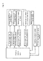
- Figure 7 is a block diagram to show the control system in the second embodiment. Table 2 shows the procedure in the second embodiment of the present invention.
- the existing ladles can be used only by changing the program. Especially, during the steps from the starting to stopping of the pouring, using the teaching playback system and the virtual pouring point center system enables the pouring to be executed by an extremely simple shaft arrangement.
- the support means for the ladle is tilted by drive means through the sector gear, it is also possible to tilt the support means through a chain and other transmission means.
- the ladle can be exchanged by a ladle carrier device (not shown) such as a hoist crane, a forklift, etc. Further, the change can be carried out by providing and using drive rollers.
- the present invention can establish pouring at a lower level by adjusting the relation between the movement along the X-axis and the Y-axis and the tilt angle of the first axis of rotation.
- the automatic pouring device will be more compact and at a lower price and can give a remarkable energy-saving effect, since only three servomotors, for the driving relating to the X-axis, the Y-axis, and the tilting, are used.
- the ladle 2 is put on the L-shaped arm 7, which is one of the elements of the support means pivotably mounted on the tilting frame, which in turn is pivotably mounted on the fixed frame F.
- the ladle 2 is put on the cantilever-type, L-shaped arm 7.
- the present invention is not limited to this arrangement.
- a U-shaped arm 71 may be tiltably mounted on a pair of fixed frames F, F1, which are upwardly mounted on the upper cart 51.
- the ladle 2 is placed on the U-shaped arm 71, which is what is called a simple beam.
- the reference number 41 denotes the lower cart.
- the sector frame G1 and the servomotor M2 which are the components of the support means, and the tilting frame S, may also be assembled to the fixed frame F1.
- the ladle 2 may be smoothly tilted by synchronously driving the pair of servomotors M2.
Abstract
Description
- The present invention relates to an automatic pouring method and an automatic pouring device. Specifically, it relates to an automatic pouring method that can make a pouring device simple and compact, and an automatic pouring device that can carries out that pouring method.
-
- Prior-art Patent 1:
JP 06-190541 A 03135/92-4 - Prior-art Patent 2:
WO99/00205 JP 2001-507631 A - Prior-art Patent 3:
JP 07-112270 A - Prior-art Patent 2:
JP 09-1320 A - Prior-
art Patent 1 discloses controlling the tilt of a ladle by the two rotating means connected to the ladle to pour molten metal from the ladle to a mold, as shown inFigure 2 of it. The first rotating means is an actuator for vertically moving a tilting shaft disposed near the pouring point of the ladle. By that vertical movement, the ladle is rotated about the center of gravity S of the molten metal (the center acts as a virtual axis of rotation). The second rotating means is a suspending wire connected to the ladle at the point D for rotating the ladle about the point K, which is the axis of rotation of the tilting shaft. Specifically, by moving the tilting shaft downward and upward by the actuator to rotate the ladle about the point S at the point of pouring start and stop, the energy generated in the molten metal movement is minimized, thus minimizing the momentum of the molten metal and hence shortening the pouring cycle. When the pouring is to be stopped (i.e., the ladle shown inFigure 2 is rotated clockwise), the rotating rate at the point S can be made zero by applying a high rotating rate to the point K and applying a low rotating rate to the point D (seeFigure 3 ). When the pouring starts, by applying similar rotating rates to them counterclockwise, the rotating rate at the point S can be made zero. Prior-art Patent 1 also discloses moving a structure laterally that supports the first and second rotating means so that the pouring point of the ladle approaches the pouring cup of the mold, as shown inFigure 4 . The first and second rotating means are controlled manually or using a program.
The pouring device of prior-art Patent 1 requires a large-scale device (a tower), and it tends to cause problems due to the pouring that is carried out from a higher level, namely, an unstable pouring with turbulent flows, defects of sand and/or gas inclusion, and the like.
Prior-art Patent 2 discloses a device for pouring molten metal in a mold by tilting a ladle about the axis of rotation A of a tilting shaft and by moving the ladle along an X-axis (the directions in wich the ladle moves toward and away from the mold) and a Z-axis (the vertical directions) to always keep a theoretical (virtual) pouring point, which is near the pouring point, in the lowest possible position relative to the mold. The ladle is moved along the X-axis, a Y-axis (the directions along the molding line), and the Z-axis by a longitudinal cart, a lateral cart, and a suspension wire, respectively, and is tilted by a drive motor. Since the pouring device of this prior-art Patent 2 also requires a large tower, it tends to cause problems in that it becomes large, to consume great energy, and to be at a high cost. Further, if a tall tower is used, its center of gravity will be located at a high level, causing another problem in that great vibrations generate due to the movement of the pouring device, making pouring accuracy worse. In addition, the tall tower causes another problem in that it limits the transportation path and hence the transportation means, resulting in a longer time to change the ladle. The tall tower causes a further problem in that it blocks its peripheral sight, making it difficult to see if the site is safe under the dangerous working environment where the molten metal is handled.
Prior-art Patent 3 discloses pouring molten metal from a tiltable ladle into a mold by tiltably supporting the ladle by a tilting shaft at the tilting center (this center is supposed to be substantially positioned at the center of gravity of the ladle) and by rotating the tilting shaft by a drive motor about the tilting center, and by simultaneously moving the tilting shaft so that its axis (the tilting center) moves along the circular locus about the pouring point of the ladle so as to keep the pouring point (or a virtual pouring point near that pouring point) in one constant position relative to the mold (i.e., thehorizontal distance 1 and the vertical distance h of the pouring point from the pouring cup of the mold are kept). The ladle is supported by a supporting element lying under it. Moving the tilting shaft along the circular locus about the pouring point when the tilting shaft is rotated (i.e., the ladle is tilted) by the motor is achieved by moving the supporting element along a Y-axis (the directions in which the ladle moves toward and away from the mold) and a Z-axis (the vertical directions). The movement of the ladle along the Y-axis is achieved by a cart, and the movement of the ladle along the Z-axis is achieved by a lifter. The movement of the ladle along the Y-axis and the Z-axis to be generated when it is tilted, is controlled by a controller according to a control flow. The controller also controls the rotating rate of the tilting shaft (i.e., the tilting rate of the ladle) to control the varying rate of the surface of the molten metal. It is called here "a virtual pouring point center system" to rotate the tilting shaft about the virtual pouring point to keep the virtual pouring point in a constant position relative to the pouring cup of the mold, as in prior-art Patent 3.
Prior-art Patent 4 relates to the improvement of the patent of prior-art Patent 3. In prior-art Patent 3, the molten metal may be poured outside the pouring cup of the mold during the pouring if the rate and quantity of the metal flow vary due to the tilt of the ladle. To improve this issue, in prior-art Patent 4 the tilting shaft is moved along a locus that slightly shifts from the circular locus of the tilting shaft about the virtual pouring point of prior-art Patent 3. The movement of the supporting element for the ladle along the Y-axis is achieved by a cart, and its movement along the Z-axis is achieved by an actuator. The tilt of the ladle about the tilting center is achieved by a sector gear secured to the ladle and a means for rotating the sector gear.
In any one of the prior-art Patents, 1-4, the movement of the ladle in the Z-axis is carried out by an actuator, a chain, or a lifter, or the combination of them. Accordingly, the pouring device still have a problem that they are tall. - The present invention has been conceived to solve the above problems. It aims to provide an automatic pouring method that can make the pouring device simple and compact by improving the conventional pouring devices, without using a tower or any driving device for vertical moving the ladle such as an actuator or the like and provide an automatic pouring device that can carries out the pouring method of the present invention. Further, the present invention also aims to provide an automatic pouring device that gives a high precision pouring and easy checking on the safety, and that enables one to easily change the ladle.
- To the above end, the automatic pouring method of the present invention is a method using a ladle to be tilted for pouring molten metal into a pouring cup of at least one flaskless or tight-flask mold in at least one pouring device movable along an X-axis parallel to a molding line in which the at least one mold is transferred, wherein the ladle is movable along a Y-axis perpendicular to the molding line in a horizontal plane, and the pouring is carried out just by moving the ladle along the X-axis and the Y-axis and by tilting the ladle about a first axis of rotation, without vertically moving the ladle.
Also, to the above end, the automatic pouring device of the present invention is one for pouring molten metal from a tiltable ladle into at least one mold in a molding line, comprising: a lower cart movable along an X-axis parallel to the molding line; an upper cart mounted on the lower cart for laterally moving along a Y-axis perpendicular the molding line in a horizontal plane; a fixed frame fixedly mounted on the upper cart; a first tilting means for tilting the ladle about a first axis of rotation on the fixed frame; and an electric control unit provided with a program that just controls the movement of the ladle along the X-axis and the Y-axis and the tilt of the ladle about the first axis of rotation, without vertically moving the ladle. - According to the automatic pouring method of the present invention, since without using any drive device for vertically moving the ladle, it moves relative to the mold along the Y-axis perpendicular to the molding line in a horizontal plane and tilts about the first axis of rotation, and since the pouring is carried out by moving the ladle along the X-axis and the Y-axis and tilting it about the first axis of rotation, the problems such as the unstable pouring, the sand inclusion, and the gaseous defects, are eliminated, and the good pouring is carried out with the ladle being positioned at a low level.
Further, according to the automatic pouring device of the present invention, since the drive device for vertically moving the ladle is not used, advantageously the pouring device will be simple and compact. Further, since the center of gravity of the pouring device can be lowered, the vibrations caused by its movement is reduced, and the pouring accuracy is improved. Additionally, since any elevating device such as a tower is not used, the transportation and the replacement of the ladle is easy, and the working efficiency is improved. In addition, eliminating any elevating device such as a tower gives a good sight in the site and enables anyone to check the safety under the dangerous environment where the molten metal is handled.
Additionally, according to the device of the present invention, the electric control unit controls the servomotors for moving and tilting the ladle during the pouring. Accordingly, the invention will be appropriately carried out for low volume production of a wide variety of products of casts just by modifying the program for the positions of parameters of the poured weights of the molten metal, the pouring cups, etc. - Further, according to one aspect of the present invention, since the ladle can also be tilted about a second axis of rotation that is located closer to the center of gravity of the ladle than is the first axis of rotation, the freedom of the ladle is increased, allowing the pouring device to work for various pouring.
In the present invention, the first axis of rotation may be used for tilting the ladle at least for a period from the starting of the pouring to the time just before the stopping of the pouring. The second axis of rotation may be used at least for tilting back the ladle when the pouring is stopped.
The second axis of rotation may be located near the center of gravity of the ladle so that it is tilted back about the axis near its center of gravity. Since in that case the movement of the molten metal in the ladle is less and the pouring is stopped with the tip of the ladle being moved upward, the stopping of the pouring is quickly carried out, greatly improving the pouring accuracy. If the ladle is tilt back about the first axis of rotation, the molten metal moves by a great distance about that axis, causing the surface of the molten metal to vibrate, thereby delaying the completion of the pouring and worsening the pouring accuracy.
Since in this aspect of the present invention the ladle is tilted about the first axis of rotation and the second axes of rotation, which differs from the first one, and since the tilt by the first axis of rotation is the tilt about a point at the tip of the ladle for pouring and the tilt by the second axis of rotation is the tilt back of the ladle about a point near the center of gravity of the ladle for stopping the pouring, the pouring is quickly stopped, and the pouring accuracy is greatly improved. - In addition, in the present invention the position along the Y-axis perpendicular to the molding line in a horizontal plane, and the tilt angles about the first and second axes of rotation, of the ladle, can be conditionally controlled at least during the pouring, for the flow line of the molten metal that varies depending on the properties of the molten metal and the shape of the ladle.
By using this conditioned control, the present invention can quickly work for the change in the pouring weight, the change in the pouring rate, and the change in the flow line, caused by the variation of the tilt angle or angles. Further, the present invention can quickly work for the change in the position the pouring cup. In addition, in the present invention the control of the tilt and the control of the movement along the X-axis and the Y-axis, of the ladle, can be simultaneously carried out at least for a period from the starting to the stopping of the pouring. - By this control, said virtual pouring point center system, the teaching playback system, which will be explained below, and the synchronous pouring system, which will also be explained below, can be used.
In the present invention the teaching playback system can be used to utilize the technique of the skilled worker.
In the teaching playback system, first the skill worker actually pours molten metal from the ladle into one or a few molds, and the relation between the position along the Y-axis, the tilt angles of the shafts (the axes of rotation), the pouring rate, and the time, for that pouring by the worker is stored as a program in the electric control unit. If the product to be cast is changed, a program for that casting is then similarly stored. The teaching playback system is the system where one of the stored programs is selected or changed for use for a product to be actually cast. By using this teaching playback system, the optimum pouring can be immediately achieved for low volume production of a wide variety of products. By the way, the inventors have experienced many times that the pouring accuracy was low when this teaching playback system was not used, but just the mathematical principle computing system was used, since the shape of the ladle or the shape of the cavity of the mold differs.
In addition, the synchronous pouring system can be used in the present invention to establish the pouring by a single pouring device for the molding line that travels at a high speed.
The synchronous pouring system is a method of continuing the pouring even when the mold is traveling at the starting of the pouring or during the pouring. This is achieved, for example, by attaching a sensor to a device that transfer the mold for detecting the transfer rate of the mold, by using a servomotor or an inverter-controlled motor as a drive unit for the lower cart of the pouring device, and by driving the drive unit so that the lower cart is traveled at the same rate as the detected traveling rate of the mold (the traveling rate of the flask when the mold is tight-flask).
In the present invention, scaling the poured molten metal is achieved by always measuring the total weight of the lower cart or the ladle, by inputting the signal on the measured weight to the electric control unit, and by calculating the weight of the molten metal remaining in the ladle and the weight of the poured molten metal. When the weight of the poured molten metal reaches the predetermined weight, the pouring is ended (the weight-feedback system). -
-
Figure 1 is a schematic front view of the first embodiment of the automatic pouring device of the present invention. -
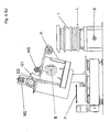
Figure 2 is a side view of the automatic pouring device ofFigure 1 . -
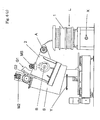
Figure 3 is a sectional view taken along the line A1-A1 inFigure 2 . -
Figure 4 is a sectional view taken along the line A2-A2 inFigure 2 . -
Figure 5 is an explanatory drawing for the first example of the control in the present invention. -
Figure 6(a) is a schematic front view showing the position of the starting point of the operation in the first embodiment of the present invention. -
Figure 6(b) is a view showing the step of preparation for pouring. -
Figure 6(c) is a view showing the step of starting pouring. -
Figure 6(d) is a view showing the step of stopping pouring. -
Figure 6(e) is a view showing the step of restarting pouring after the pouring is once stopped. -
Figure 6(f) is a view showing the step of tapping all molten metal from the ladle. -
Figure 7 is an explanatory drawing for the second example of the control in the present invention. -
Figure 8 is a side view of another embodiment of the automatic pouring device of the present invention. -
Figure 9 is a side view of a further embodiment of the automatic pouring device of the present invention. - Below the best mode for carrying out the invention is described. The automatic pouring device of the present invention is an automatic pouring device to pour molten metal from a ladle to one or more tight-flask or flaskless molds that travel along a molding line. The automatic pouring device includes a lower cart that travels along the molding line; an upper cart that travels on the lower cart in forward and backward directions that are perpendicular to the molding line, a frame uprightly and fixedly mounted on the upper cart, a first tilting means for tilting the ladle about a first axis of rotation, and an electric control unit provided with a program to control the movement of the ladle in X and Y directions and control the tilt of the ladle about the first axis of rotation.
- The pouring method and device of the present invention can be applied to either a tight-flask mold or a flaskless mold.
The wording "at least one pouring device" is used for the pouring method of the present invention, because plural pouring devices may be used according to the molding line.
The wording "a ladle that can pour molten metal in the pouring cup of the mold by tilting" denotes that the present invention is not related to a stopper-type pouring ladle or a pressurized pouring ladle, but related to a ladle that has a center of rotation. The shape of the cross section of the ladle of the invention is, for instance, a sector or a rectangle.
In the present invention, the term "automatic pouring" denotes automatically doing at least some operation that is conventionally manually done by an operator or operators. In the "automatic pouring," the ladle is held, located in position, and tilted; the position in which the molten metal flows out of the ladle and the weight of the poured molten metal are monitored and then controlled by adjusting the position and the tilt angle of the ladle; and the ladle is refilled with molten metal when the molten metal in it is used. - In the pouring method and device of the present invention, the term "the tilt angle about the first axis of rotation" denotes a relative angle with respect to the tilting frame of the
ladle 2.
Further, the term "the tilt angle about the second axis of rotation" denotes a relative angle of the tilting frame S with respect to the fixing frame F. - The ladle of the present invention may be exchanged by a transportation means such as a hoist crane, a forklift, or the like. Further, it may be automatically and quickly changed by attaching drive rollers to a ladle-supporting frame and by driving the drive rollers together with other drive rollers attached to a fixed side.
Since the pouring device of the invention has no tall tower, there is nothing to hinder the transfer path of the ladle when it is changed, and thus the transportation means and the transfer path are not limited. This allows the ladle that is to be changed after it has completed the pouring to be promptly exchanged for another ladle, by using a hoist crane, a forklift, or any other transfer means that moves perpendicularly to this ladle.
In the present invention, "a first tilting means for tilting the ladle on the fixed frame about a first axis of rotation" comprises, for example, a sector frame, for supporting the ladle, pivotably mounted on a tilting shaft having the first axis of rotation; a sector gear disposed around the periphery of the sector frame for tilting the sector frame, and a servomotor for driving the sector gear. Through the sector gear the ladle is tilted about the first axis of rotation by the servomotor.
In the present invention, "a second tilting means for further tilting the ladle about a second axis of rotation" comprises, for example, a tilting shaft having a second axis of rotation and passing through a fixed frame, which is in turn uprightly mounted on an upper cart; a servomotor as a drive means, coupled to the tilting shaft; and a tilting frame pivotally mounted on the tilting shaft at the other side, i.e., opposite the side to which the servomotor is coupled. Thus the tilting frame is tilted about the second axis of rotation by the servomotor. Further, the tilting frame is pivotally mounted on the sector frame.
Thus, even if the sector frame does not move, the ladle can be titled by the tilting frame about the second axis of rotation, which differs from the first axis of rotation. When the tilting frame is not moving, the ladle can be tilted by the sector frame about the first axis of rotation.
In the present invention, the means for supporting the ladle is a part mounted on a side surface of the sector frame for supporting the ladle, and the shape of the part differs depending on the shape of the ladle and the method of changing the ladle.
The sector frame is a frame that is pivotably mounted on the tilting shaft having the first axis of rotation, and that directly supports the ladle on it. The sector frame is formed with a sector gear at the circular edge. The center of the sector gear coincides with the first axis of rotation. The sector frame is arranged to be driven to rotate about the first axis of rotation by a drive motor connected to the sector gear. - Below, the automatic pouring method and device of the present invention will be explained in detail by referring to the accompanying drawings.
-
Figures 1-4 show the first embodiment of the present invention. This embodiment is an example where molten metal is poured from a ladle in molds arranged on a molding line. The embodiment uses an X-axis (extending perpendicularly to the sheet ofFigure 1 ), a Y-axis (extending in the rightward and leftward directions in the sheet ofFigure 1 ), a first axis of rotation A (positioned near the tip of the pouring mouth of the ladle in this example), and a second axis of rotation B (in this example positioned near the center of gravity of the ladle).
InFigure 1 ,molds 1 are arranged in line with the molding line L and move intermittently. Aladle 2 pours molten metal in thesemolds 1. An automatic pouringdevice 3 is used for this pouring.
The automatic pouringdevice 3 comprises alower cart 4 movable via wheels 4b along a pair of rails 4a disposed alongside the molding line L (X-axis), anupper cart 5 movable via front and rear wheels 5a, 5a on thelower cart 4 in a horizontal direction (Y-axis) perpendicular to the molding line L, a frame F uprightly and fixedly mounted on theupper cart 5, a tilting frame S pivotably supported by this fixed frame F, and a supporting means pivotably supported by the tilting frame S for supporting theladle 2.
The movement of thelower cart 4 in the forward and backward directions (X-axis), the movement of theupper cart 5 in the lateral (Y-axis) direction, the tilt of the tiling frame S, and the tilt of theladle 2, are all servo-driven by four respective servomotors, namely, a servomotor M5 for the forward and backward movement, a servomotor M4 for the lateral movement, a tilting servomotor MS for the tilting frame, and a tilting servomotor M2 for the ladle.
Via a sector-shaped sector frame G1 pivotably mounted on a tilting frame S, acting as a support means for theladle 2; an L-shapedarm 7 disposed at a side surface of the sector frame G1, and a sector gear G2 engaging with adrive gear 6 of the servomotor M2, theladle 2 is placed on a horizontal part 7a of the L-shapedarm 7 and is arranged to be tilted together with the sector frame G1 and thearm 7 about the first axis of rotation A. Further, thearm 7 allows awheel 8, pivotably mounted on the bottom of the arm, to be tiltably supported by aliner 9 disposed on the side surface of the tilting frame S. Thisliner 9 is disposed in at least a range within which the sector frame G1 tilts. A liner 10 (Figure 4 ) is also disposed on a back surface of the tilting frame S. Theliner 10 is disposed in at least a range within which the tilting frame S tilts. The tilting frame S is supported by awheel 11, which is in turn pivotably supported by the fixed frame F.
The tilting frame S, which is pivotably supported by the fixed frame F, is arranged so that it is tilted by the drive servomotor MS about the second axis of rotation B. Thus theladle 2 is tilted not only about the first axis of rotation A, but also about the second axis of rotation B, which differs from the first axis of rotation A. Accordingly, by just moving theladle 2 along the X-axis and Y-axis and tilting it about the axes of rotation A and B when theladle 2 pours the molten metal, the tilt angles of it about both the first and second axes A and B, and the position of it along the Y-axis (which perpendicularly intersects the molding line L in a horizontal plane), are optimally adjusted. - All the servomotors, M4, M5, MS, and M2, are electrically connected with an electric control unit. Below, controlling them is explained by referring to
Figure 5 .
The electric control unit includes a program to control the servomotors in relation to the movement of the ladle in the X-and Y-directions and the tilt of it about the first and second axes. This program is called thereby controlling the servomotors so that the ladle pours the molten metal as programmed.
Further, a measuring means for measuring the weight of the poured molten metal continuously measures the total weight of theupper cart 5 with the load cell (not shown) and sends and inputs a signal on the measurements to the electric control unit to calculate the weight of the molten metal remaining in the ladle and the weight of the poured molten metal. The measuring means then judges that the predetermined weight of the molten metal has been poured when the calculated weight of the poured molten metal reaches that predetermined weight. The measuring means then instructs that pouring be stopped by employing a measured-weight feedback system. The weight of the poured molten metal may be alternatively measured by continuously scaling the total weight of theladle 2 by a load cell, which is a measuring means to control the weight of molten metal to be poured.
Further, as will be explained below, the program may employ a teaching playback system of an optimum pouring program and employ an optimum alignment for the tip of the ladle using the virtual pouring point center system where the axis of rotation of the pouring point is not fixed.
Furthermore, since in the pouring operation the temperature and quality of the molten metal, the tilt angle of the ladle, and the shape, etc., of the ladle, change, during the pouring the flow line of the molten metal changes. Thus a study-and-feedback system may also be applied to carry out the optimum pouring in which these factors of the changes are continuously studied and fed back. - The operation of the automatic pouring device of the present invention will be explained below.
Figure 6 shows an example of the automatic pouring operation of the automatic pouring device shown inFigures 1-4 .Figure 6(a) corresponds toFigure 1 and shows the original position, i.e., the starting position, of the automatic pouringdevice 3 for the automatic pouring.Figure 6(b) shows the step of pouring preparation.Figure 6(c) shows the step of pouring start.Figure 6(d) shows the step of pouring stop.Figure 6(e) shows the step of restarting pouring after the pouring is once stopped.Figure 6(f) shows the step of tapping all molten metal from the ladle. The step of tapping the molten metal is not always carried out on the mold. - In the starting position in
Figure 6(a) , theupper cart 5 is positioned in the retraction (back) end of its passage, away from amold 1. The tilting frame S is kept horizontal (i.e., the tilt angle of it is 0 degree). Accordingly, the bottom of the tilting frame S is now horizontal. Further, theladle 2 is also kept horizontal (the tilt angle of it is 0 degree). Accordingly, the surface of the molten metal in theladle 2 is horizontal. Since thelower cart 4 can move alongside the X-axis, the pouringdevice 3 can move to the places where the molds to be poured with molten metal stand. - In the step of the pouring preparation, shown in
Figure 6(b) , the pouring is ready to start, with theladle 2 fully refilled with molten metal. Theupper cart 5 moves to the forward distal end of its passage, near themold 1, to approach it. The tilting frame S is tilted from the horizontal position (where the tilt angle is zero) by, for example, 10 degrees. Theladle 2 is kept horizontal (the tilt angle of it is 0 degree). Thus the relative tilt angle of the ladle to the tilting frame S is zero, and the bottom of the tilting frame S and the bottom of theladle 2 are parallel. Below the term "tilt angle" is used in this meaning. -
Figure 6(c) shows the step of pouring start. The pouring begins. Theupper cart 5 approaches themold 1 and is held at the distal end. The tilt angle of the tilting frame S is kept at ten degrees. At the same time theladle 2 is tilted from zero to five degrees. This rate of changing the tilt angle is changed by the program. -
Figure 6(d) shows the step of pouring stop, i.e., pouring end. Theupper cart 5 is held at the distal end near themold 1. The tilting frame S is tilted back so that its tilt angle is gradually changed from 10 degrees to 5 degrees. During this tilting back the tilt angle of the ladle is kept at 5 degrees. Although for the end of the pouring the measured-weight feedback system (where the amount of the poured molten metal is measured, and then the pouring is finished if the measured amount becomes a predetermined one) is here used, other systems may be used. There are, for example, an optical controlling system, where the surface level of molten metal in a pouring cup is monitored by a camera, a teaching playback system, a study-and-feedback system, etc. Any one of them may be used. -
Figure 6(e) shows the step of starting pouring molten metal into another mold after stopping pouring for the previous mold. Theupper cart 5 is held at the distal end near themold 1. The tilting frame S is tilted from a position at 5 degrees to one at 10 degrees. Simultaneously, the ladle is tilted from a position at 5 degrees to one at 10 degrees.
It should be understood that the relative movement of the ladle from onemold 1 to another one is achieved by either moving thelower cart 4 to a next mold to be poured with molten metal or by advancingmolds 1 along the molding line L. -
Figure 6(f) shows the step of tapping all the molten metal from theladle 2. Theupper cart 5 is held at the distal end near themold 1. The tilting frame S is held with its tilt angle being at ten degrees. Theladle 2 is held with its tilt angle being more than ten degrees, for example, between 50-70 degrees. By this, all the molten metal is tapped from theladle 2. However, this step is not always carried out.
Normally, if the amount of molten metal remaining in the ladle is less than the amount necessary for the next pouring after pouring is repeated plural times, the pouring device automatically returns to the starting position, and the ladle is refilled with molten metal. There are various ways to supply molten metal in the ladle. One is to transfer molten metal carried in another ladle (not shown) to the pouringladle 2 while it is held on the pouring device. Another way is a ladle-removing or ladle-exchanging method, where theladle 2 is first removed from the automatic pouring device to receive molten metal and then re-mounted on the pouring device after it is refilled with molten metal, or the removed ladle is exchanged with another ladle refilled with molten metal. Any one of these ways may be used.
The relation between the movement along the X-axis and Y-axis, the (relative) tilt angle (of theladle 2 to the tilting frame) about the first axis of rotation, and the (relative) tilt angle (of the tilting frame S to the fixed frame F), all discussed above, and the pouring steps, also discussed above, are summarized in Table 1 below. - Table 1
Table 1 (a) (b) (c) (d) (e) (f) Position Original position Position for preparing pouring Position for starting pouring Position for stopping pouring Position for re-pouring Position for tapping molten metal What is to be done Ladle is refilled with molten metal Preparing for pouring Pouring is started Pouring is stopped Re-pouring for a next mold All molten metal remaining in the ladle is tapped X-axis Lower cart moves to a position near the mold to be poured with molten metal Lower cart is positioned relative to a position near the mold to be poured with molten metal Y-axis Upper cart is held at the proximal end, spaced apart from the mold Upper cart moves to the distal end to approach the mold Upper cart is held at the distal end near the mold Upper cart is held at the distal end near the mold Upper cart is held at the distal end near the mold Upper cart is held at the distal end near the mold Tilt angle of the tiling frame 0° Changed from 0° to 10° 10° Changed from 10° to 5° Changed from 10° to 5° 10° Tilt angle of the ladle 0° 0° Changed from 0° to 5° 5° Changed from 5° to 10° 50°-70°
This embodiment is one example of the pouring steps. It also may be possible to execute some steps at the same time as long as the operations of the steps do not interfere with each other. Some steps that could be simultaneously executed may be sequentially executed.
Further, the adjustment may be made by the teaching playback system, etc., according to the flow line of the molten metal, which changes depending on the nature of the molten metal, the shape of the ladle, etc. Since the program can be promptly switched, this pouring can be applied for low volume production of wide variety of products. In these cases the control of the movement along the X-axis and Y-axis and the tilt of the ladle are servo-driven at the same time, when necessary, at least from the starting to stopping of the pouring. - Below a teaching playback system and the virtual pouring point center system, each of which is an effective system when used from the starting to the stopping of the pouring, is now described in detail.
- In this embodiment, the teaching playback system may be used to utilize the skill of the expert worker. By the teaching playback system, the expert worker sets the way of pouring only the first time, and the next pouring is repeated by using a teaching playback program, which learned the teaching of the best pouring program. Namely, when the movement along the X-axis and Y-axis and the tilt of the
ladle 2 are controlled at least from the starting to the stopping of pouring, only the first time does the expert operator pour the molten metal from the ladle to the mold. The relation between the position in the Y direction, the tilt angles about the axes of rotation, the pouring rate, and the time for this operation, are stored in the electric control unit as a program. Similarly, further programs are also stored in it when the products to be cast change. One of the programs that is determined, prior to casting, to match a given product to be cast, is selected in view of the pattern number, the flask number, the product number, etc. The selected program is called and used for pouring. Further, the teaching playback system can be started when the pouring starts. This starting of the pouring may be detected by an optical means by detecting the occurrence of the molten metal being tapped from the ladle, and it is then fed back so that a pouring program selected or changed for the best pouring for a given product is carried out.
Further, the teaching playback system can be terminated when the pouring ends. When the measured weight of the poured molten metal reaches the predetermined amount, the end of the pouring may be fed back as the point of completion of the running pouring program, which has been changed for the given product to be cast. - Below the embodiment that uses the virtual pouring point center system will be explained in detail. In this system, while the ladle is being tilted about the first axis of rotation, the second axis of rotation is moved along a circular locus about the point of the pouring mouth of the ladle at which the molten metal starts to fall or about a virtual pouring point that is determined as a point near that point of the pouring mouth. Namely, during the pouring the ladle is controlled to move about the first axis of rotation A, about the second axis of rotation B, and along the Y-axis, so that the ladle itself rotates about the first axis of rotation A, and so that the second axis of rotation B moves along the circular locus about the point of the pouring mouth of the ladle at which the molten metal starts to fall or about the virtual pouring point so determined. By this control for the movement, the relation between the position of the pouring cup of the
mold 1 and the position of the point of the pouring mouth of the ladle at which the molten metal stars to fall is substantially maintained constant.
In this embodiment, theladle 2, which is placed on the horizontal part 7a of thearm 7, is arranged to be tilted about the first axis of rotation A by the servomotor M2 together with the sector frame G1 and thearm 7. Further, the tilting frame S, which is pivotably mounted on the fixed frame F, is arranged to be tilted about the second axis of rotation B by the drive servomotor MS.
The tilt angles of the first axis of rotation A and the second axis of rotation B may be detected by suitable angle detection means (not shown), such as encoders.
Further, the relation between the position ofladle 2 along the Y-axis, the tilt angles of the axes of rotation, the pouring rate, and the time, is stored as a program in the electric control unit. The tilt angles of theladle 2 are detected by the angle detection means, or the weight of the poured molten metal is measured by the measuring means for measuring the weight of the poured molten metal, and according to the variations of these factors the tilting rates of the ladle, etc., are then controlled by the electric control unit.
When the pouring starts, it is checked by a position-detection means (not shown) at the moment where theladle 2 starts to rotate, if the position of the pouring cup of themold 1 and the pouring point of the ladle at which the molten metal starts to fall are kept in the predetermined relation. If so, pouring the molten metal will be started. Further, according to the tilt angle of theladle 2, the electric control unit then sends drive signals to the servomotor MS for tilting the tilting frame and to the servomotor M2 for tilting the ladle, so that the predetermined tilting rates are obtained.
After the predetermined weight of the molten metal is poured in the mold, the ladle is then tilted back about the second axis of rotation B.
Since thus the virtual pouring point center system can be quickly prepared for the varying weight of the molten metal to be poured even if a ladle has a varying molten metal surface area according to its tilt angle, it can use any existing ladles that have a cross section other than a sector. Further, also if the pouring mouth of theladle 2 and the pouring cup of themold 1 are extremely close to each other, the predetermined relation between the position of the point of the pouring mouth of the ladle at which the molten metal starts to fall and the position of the pouring cup of the mold is maintained, and the flow line of the poured molten metal between the ladle and the pouring cup of the mold hence is kept within a constant range, providing good pouring. - In the first embodiment the tilt of the two axes of rotation (axes of rotation A and B) is used. However, if the pouring is not intended for low volume production of a wide variety of products, but intended for producing, for example, a large volume of the same products, the tilt of only one axis of rotation may be used. Further, this is especially suitable to the molding line in the vertical-type flaskless-mold molding machine, since the height of that molding machine is always constant.
If the tilt of only one axis of rotation is used, the initial height of the pouring point ofladle 2 at the starting point (the original position) should be adjusted to be at an appropriate level higher than the upper surface of themold 1. Further, when in the original position, the first axis of rotation of theladle 2 is in a position closer to the molding line L than is the fixed frame F.
When the virtual pouring point center system is used inembodiment 2, the pouring point of the ladle is positioned at an optimum level relative to the level of the pouring cup of the mold (wherein the ladle will be rotated at a point near its center of gravity about the pouring point), and the lateral position of the ladle is also optimally adjusted relative to the lateral position of the pouring cup by the lateral travel of the upper cart.
Further,Figure 7 is a block diagram to show the control system in the second embodiment. Table 2 shows the procedure in the second embodiment of the present invention. - Table 2
Table 2 (a) (b) (c) (d) (e) (f) Position Original position Position for preparing pouring Position for starting pouring Position for stopping pouring Position for re-pouring Position for tapping molten metal What is to be done Ladle is refilled with molten metal Preparing for pouring Pouring is started Pouring is stopped Re-pouring for a next mold All molten metal remaining in the ladle is tapped X-axis Lower cart moves to a position near the mold to be poured with molten metal Lower cart is positioned relative to a position near the mold to be poured with molten metal Y-axis Upper cart is held at the proximal end, spaced apart from the mold Upper cart moves to the distal end to approach the mold Upper cart is held at the distal end near the mold Upper cart is held at the distal end near the mold Upper cart is held at the distal end near the mold Upper cart is held at the distal end near the mold Tilt angle of the ladle 0° 0° Changed from 0° to 5° 5° Changed from 5° to 10° 50°-70°
Further, though the support means for the ladle is tilted by drive means through the sector gear, it is also possible to tilt the support means through a chain and other transmission means.
Further, the ladle can be exchanged by a ladle carrier device (not shown) such as a hoist crane, a forklift, etc. Further, the change can be carried out by providing and using drive rollers. - From the foregoing explanation, clearly the present invention can establish pouring at a lower level by adjusting the relation between the movement along the X-axis and the Y-axis and the tilt angle of the first axis of rotation.
Especially, in this embodiment, the automatic pouring device will be more compact and at a lower price and can give a remarkable energy-saving effect, since only three servomotors, for the driving relating to the X-axis, the Y-axis, and the tilting, are used. - In both the first and second embodiments of the pouring
devices 3, theladle 2 is put on the L-shapedarm 7, which is one of the elements of the support means pivotably mounted on the tilting frame, which in turn is pivotably mounted on the fixed frame F. Specifically, in the embodiments theladle 2 is put on the cantilever-type, L-shapedarm 7. However, the present invention is not limited to this arrangement. For example, like the pouring device 31 shown inFigure 8 , in place of the L-shapedarm 7, aU-shaped arm 71 may be tiltably mounted on a pair of fixed frames F, F1, which are upwardly mounted on theupper cart 51. Thus theladle 2 is placed on theU-shaped arm 71, which is what is called a simple beam. Since this arrangement stably holds theladle 2, the capacity of theladle 2 can be enlarged. InFigure 8 , the reference number 41 denotes the lower cart. The same reference numbers are used for the same elements as in the above embodiment.
Further, as shown inFigure 9 , the sector frame G1 and the servomotor M2, which are the components of the support means, and the tilting frame S, may also be assembled to the fixed frame F1. In the pouring device 32 shown inFigure 9 theladle 2 may be smoothly tilted by synchronously driving the pair of servomotors M2.
Claims (21)
- An automatic pouring method using a ladle to be tilted for pouring molten metal into a pouring cup of at least one flaskless or tight-flask mold in at least one pouring device movable along an X-axis parallel to a molding line in which the at least one mold is transferred,
wherein the ladle is movable along a Y-axis perpendicular to the molding line in a horizontal plane, and the pouring is carried out just by moving the ladle along the X-axis and the Y-axis and by tilting the ladle about a first axis of rotation, without vertically moving the ladle. - The automatic pouring method of claim 1, wherein the ladle is further tiltable about a second axis of rotation that differs from the first axis of rotation, and that is located at a position closer to the center of the ladle than is the first axis of rotation, and wherein the pouring is carried out by moving the ladle along the X-axis and the Y-axis and by tilting the ladle about the first and second axes of rotation.
- The automatic pouring method of claim 2, wherein the first axis of rotation is for tilting the ladle at least for a period from the starting of the pouring to the time just before the stopping of the pouring, and wherein the second axis of rotation is for tilting back the ladle at least when the pouring is stopped.
- The automatic pouring method of claim 1, 2, or 3, wherein at least one of the position along the Y-axis, which is perpendicular to the molding line in the horizontal plane; the tilt angle about the first axis of rotation, and the tilt angle about the second axis of rotation, of the ladle, is conditionally controlled at least when the molten metal is poured, for the flow line of the molten metal varying depending on the properties of the molten metal and the shape of the ladle.
- The automatic pouring method of any one of claims 1-3, wherein controlling the tilt of the ladle and controlling the movement of the ladle along the X-axis and Y-axis are simultaneously carried out at least for a period from the starting of the pouring to the stopping of the pouring.
- The automatic pouring method of any one of claims 1-3, wherein controlling the tilt of the ladle and controlling the movement of the ladle along the X-axis and Y-axis are simultaneously carried out by a teaching playback system at least for a period from the starting of the pouring to the stopping of the pouring.
- The automatic pouring method of any one of claims 1-3, wherein the time that the molten metal starts to flow out from the ladle when the molten metal is poured is detected by optical detecting means, and the detected time is fed back as the starting of the pouring.
- The automatic pouring method of any one of claims 1-3, wherein the weight of the poured molten metal is measured and then fed back as the time of stopping the pouring.
- The automatic pouring method of any one of claims 1-3, wherein the ladle is changed with another ladle by a vertically movable hoist crane, forklift, or other transportation means.
- The automatic pouring method of any one of claims 1-3, wherein the pouring is continued by moving the ladle at the same rate as the traveling rate of the mold in the molding line when the mold is moved for starting the pouring or when the mold is moved during the poring.
- An automatic pouring device for pouring molten metal from a tiltable ladle into at least one mold in a molding line, comprising:a lower cart movable along an X-axis parallel to the molding line;an upper cart mounted on the lower cart for laterally moving along a Y-axis perpendicular the molding line in a horizontal plane;a fixed frame fixedly mounted on the upper cart;a first tilting means for tilting the ladle about a first axis of rotation on the fixed frame; andan electric control unit provided with a program that just controls the movement of the ladle along the X-axis and the Y-axis and the tilt of the ladle about the first axis of rotation, without vertically moving the ladle.
- The automatic pouring device of claim 11, further including a second tilting means for tilting the ladle about a second axis of rotation that differs from the first axis of rotation, and that is located at a position closer to the center of the ladle than is the first axis of rotation.
- The automatic pouring device of claim 12, wherein the electric control unit is further provided with a program for allowing the first axis of rotation to act for tilting the ladle at least for a period from the starting of the pouring to the time just before the stopping of the pouring and allowing the second axis of rotation to act for tilting back the ladle at least when the pouring is stopped.
- The automatic pouring device of claim 11, 12, or 13, wherein the electric control unit is provided with a program for controlling and adjusting at least one of the position along the Y-axis, which is perpendicular to the molding line in the horizontal plane; the tilt angle about the first axis of rotation, and the tilt angle about the second axis of rotation, of the ladle, is conditionally controlled at least when the molten metal is poured, for the flow line of the molten metal varying depending on the properties of the molten metal and the shape of the ladle.
- The automatic pouring device of any one of claim 11-13, wherein the electric control unit is provided with a program for simultaneously controlling the tilt and the movement along the X-axis and Y-axis of the ladle at least for a period from the starting of the pouring to the stopping of the pouring.
- The automatic pouring device of any one of claim 11-13, wherein the electric control unit is provided with a teaching playback program that can run for a selected product to be cast.
- The automatic pouring device of any one of claim 11-13, further including measuring means coupled to the electric control unit for measuring the weight of the poured molten metal.
- The automatic pouring device of any one of claim 11-13, wherein a moving device for moving the mold in the molding line is provided with a sensor for detecting the traveling rate of the mold, and wherein a drive device for the lower cart includes a servomotor or an inverter-controllable drive motor for driving the lower cart at the detected traveling rate of the mold.
- The automatic pouring device of any one of claim 11-13, wherein the first tilting means tilts a support means for the ladle, which means is pivotably mounted on the tilting frame.
- The automatic pouring device of claim 19, wherein the support means for the ladle is tilted by a rotating means that includes a sector gear or a chain.
- The automatic pouring device of claim20, wherein the first axis of rotation is for directly tilting the ladle, the support means for the ladle pivotably mounted on the tilting frame is tilted for a period from the starting of the pouring to the stopping of the pouring, the second axis of rotation is for indirectly tilt the ladle, and the tilting frame pivotably mounted on the fixed frame is tilted back at least when the pouring is stopped.
Applications Claiming Priority (2)
| Application Number | Priority Date | Filing Date | Title |
|---|---|---|---|
| JP2007034175 | 2007-02-15 | ||
| JP2007052316 | 2007-03-02 |
Publications (2)
| Publication Number | Publication Date |
|---|---|
| EP1967302A1 true EP1967302A1 (en) | 2008-09-10 |
| EP1967302B1 EP1967302B1 (en) | 2009-12-30 |
Family
ID=39091878
Family Applications (1)
| Application Number | Title | Priority Date | Filing Date |
|---|---|---|---|
| EP08000222A Active EP1967302B1 (en) | 2007-02-15 | 2008-01-08 | Automatic pouring method and device |
Country Status (12)
| Country | Link |
|---|---|
| US (2) | US8327912B2 (en) |
| EP (1) | EP1967302B1 (en) |
| JP (1) | JP4564099B2 (en) |
| KR (1) | KR101119391B1 (en) |
| CN (1) | CN101244457B (en) |
| AT (1) | ATE453474T1 (en) |
| BR (1) | BRPI0721367B1 (en) |
| DE (2) | DE102008003530A1 (en) |
| DK (1) | DK1967302T3 (en) |
| ES (1) | ES2338942T3 (en) |
| TW (1) | TWI466740B (en) |
| WO (1) | WO2008099556A1 (en) |
Cited By (7)
| Publication number | Priority date | Publication date | Assignee | Title |
|---|---|---|---|---|
| WO2009119464A1 (en) * | 2008-03-25 | 2009-10-01 | Sintokogio, Ltd. | Method to control automatic pouring equipment and system therefor |
| CN101811187A (en) * | 2009-06-16 | 2010-08-25 | 新东工业株式会社 | To the method for automatic pouring machine supplying melting metal with and equipment |
| WO2010128610A1 (en) * | 2009-05-08 | 2010-11-11 | Sintokogio, Ltd. | Carriage to transport a ladle and to transfer molten metal into equipment for pouring and transportation line for transporting molten metal |
| CN104798972A (en) * | 2014-01-27 | 2015-07-29 | 上海跃祺机械制造有限公司 | Casting apparatus of colloid soft sweets, and casting method thereof |
| EP2425914A4 (en) * | 2009-04-28 | 2016-12-14 | Sintokogio Ltd | Tilting-type automatic molten metal pouring method, tilting control system, and storage medium having tilting control program stored therein |
| EP2444178A4 (en) * | 2009-06-16 | 2017-05-17 | Sintokogio, Ltd. | Automatic pouring method and facility therefor |
| IT202100003125A1 (en) * | 2021-02-12 | 2022-08-12 | Omega Sinto Foundry Machinery Ltd | "A SEMI-AUTOMATIC OR AUTOMATIC CASTING PLANT WITH CASTING LADWEIGHING DEVICE" |
Families Citing this family (65)
| Publication number | Priority date | Publication date | Assignee | Title |
|---|---|---|---|---|
| ES2304820B1 (en) * | 2005-09-30 | 2009-10-21 | Airbus España, S.L. | ULTRASOUND HEAD FOR MULTICHANNEL INSPECTION BY PULSE-ECO. |
| DE102008051224A1 (en) * | 2008-10-14 | 2010-04-29 | Scheuerle Fahrzeugfabrik Gmbh | Transport pallet for container that is filled with liquid material and includes lateral receptions and rear reception, comprises base frame with support, in which the lateral receptions of the container are receivable, and tipping device |
| WO2011004685A1 (en) * | 2009-07-06 | 2011-01-13 | 新東工業株式会社 | Apparatus and method for feeding inoculants into a flow of molten metal and automatic molten metal pouring machine |
| WO2011030618A1 (en) * | 2009-09-10 | 2011-03-17 | 新東工業株式会社 | Molten metal pouring machine control system, molten metal pouring equipment, and molten metal pouring method |
| BR112012004435A2 (en) * | 2009-09-14 | 2016-03-22 | Fujiwa Denki Co | Method of supplying molten metal from foundry furnace to shell treatment and equipment for the same. |
| DE102009042454A1 (en) * | 2009-09-23 | 2011-04-28 | Schenk Werkzeug- Und Maschinenbau Gmbh & Co. Kg | Casting container for the reception of liquid metals, comprises an external wall, which has two side walls, two lateral walls and a base and forms a container-shaped cavity accessible from top, and a lining made of refractory materials |
| CN102126019B (en) * | 2010-01-13 | 2014-12-10 | 新东工业株式会社 | Molten metal pouring device having melting furnace mounted thereon |
| JP5408793B2 (en) * | 2010-04-22 | 2014-02-05 | 新東工業株式会社 | Tilt-type automatic pouring method and storage medium storing ladle tilt control program |
| CN101875109A (en) * | 2010-06-12 | 2010-11-03 | 无锡巨力重工机械有限公司 | Improved ladle car |
| JP5408797B2 (en) * | 2010-07-06 | 2014-02-05 | 新東工業株式会社 | Pouring facilities |
| CN101941067A (en) * | 2010-08-26 | 2011-01-12 | 刘书僮 | Numerical control hot metal casting system |
| TW201208788A (en) * | 2010-08-26 | 2012-03-01 | Sintokogio Ltd | Pouring equipment and method of pouring using the pouring equipment |
| CN102151804A (en) * | 2010-11-16 | 2011-08-17 | 苏州苏铸成套装备制造有限公司 | Sand box operating vehicle device |
| CN102139366B (en) * | 2011-01-13 | 2012-10-31 | 河南中色赛尔工业炉有限公司 | Flexible hot molten metal transferring joint |
| JP5492129B2 (en) * | 2011-03-29 | 2014-05-14 | アイシン高丘株式会社 | Cast steel pouring equipment |
| JP5886686B2 (en) * | 2012-05-25 | 2016-03-16 | 東久株式会社 | Automatic pouring device and pouring method for mold |
| CN103447512A (en) * | 2012-06-01 | 2013-12-18 | 北京天哲消失模铸造技术有限公司 | Automatic hydraulic casting machine |
| CN102717055B (en) * | 2012-06-27 | 2013-11-13 | 浙江福瑞科流控机械有限公司 | Stokehole auxiliary robot |
| CN102784903A (en) * | 2012-09-11 | 2012-11-21 | 株洲冶炼集团股份有限公司 | Automatic casting device for anode plate |
| DE102012109248A1 (en) * | 2012-09-28 | 2014-04-03 | Fluxana GmbH & Co. KG | Preparation of analysis samples |
| KR101445931B1 (en) * | 2012-10-22 | 2014-10-06 | 원광이엔텍 주식회사 | Molten metal pouring apparatus for die casting |
| CN102941339B (en) * | 2012-11-01 | 2015-08-26 | 常州大学 | A kind of method and apparatus of fixing casting ladle pouring position |
| US8910699B2 (en) | 2013-03-15 | 2014-12-16 | United States Pipe And Foundry Company, Llc | Centrifugal casting method and apparatus |
| US8733424B1 (en) | 2013-03-15 | 2014-05-27 | United States Pipe And Foundry Company, Llc | Centrifugal casting method and apparatus |
| CN103157782B (en) * | 2013-04-03 | 2015-03-04 | 苏州苏铸成套装备制造有限公司 | Three-axis association full-automatic casting machine |
| CN103447513B (en) * | 2013-09-02 | 2015-10-21 | 三明学院 | A kind of medium-frequency induction furnace automatic casting control system |
| KR101340068B1 (en) * | 2013-10-07 | 2013-12-11 | (주) 캐스텍코리아 | Melt transport and tilting device |
| KR101340066B1 (en) * | 2013-10-07 | 2013-12-11 | (주) 캐스텍코리아 | Melt transport and tilting system |
| KR101340070B1 (en) * | 2013-10-07 | 2013-12-11 | (주) 캐스텍코리아 | Melt tilting system |
| KR101351082B1 (en) * | 2013-10-07 | 2014-01-13 | (주) 캐스텍코리아 | Ladle of melt transport device |
| CN103706781B (en) * | 2014-01-20 | 2015-10-07 | 湘潭大学 | A kind of gear type fixed point tilt pouring machine |
| US9205491B2 (en) * | 2014-01-21 | 2015-12-08 | GM Global Technology Operations LLC | Metal pouring method for the die casting process |
| JP5959564B2 (en) | 2014-04-01 | 2016-08-02 | 新東工業株式会社 | Ladle transport cart and molten metal transport line using it |
| JP6233187B2 (en) * | 2014-05-27 | 2017-11-22 | 新東工業株式会社 | Self-hardening mold making equipment |
| US10272489B2 (en) * | 2014-09-17 | 2019-04-30 | Sintokogio, Ltd. | Carriage for receiving molten metal with a mechanism for moving a ladle up and down, and a method for transporting molten metal |
| CN104550887B (en) * | 2015-01-04 | 2017-03-22 | 芜湖聚达汽车零部件有限公司 | Aluminum billet casting machine |
| EP3266540B1 (en) * | 2015-03-06 | 2020-05-13 | Sintokogio, Ltd. | Pouring machine and method |
| MX2017012550A (en) * | 2015-04-03 | 2018-01-30 | Sintokogio Ltd | Molten metal pouring device and molten metal pouring method. |
| DE102015107951B4 (en) | 2015-05-20 | 2018-09-13 | INDUGA Industrieöfen u. Giesserei-Anlagen GmbH & Co. KG | Method and device of a control of the casting process during casting of a casting mold by means of a gravitationally empty rotatable ladle |
| US10583479B2 (en) * | 2015-06-23 | 2020-03-10 | Rolls-Royce Corporation | Automated bi-casting |
| CN105149558A (en) * | 2015-07-30 | 2015-12-16 | 诸葛明 | Casting pouring truck with automatic pouring function |
| CN105268960B (en) * | 2015-12-01 | 2017-10-31 | 宁夏共享集团股份有限公司 | A kind of six axles casting car |
| CN105903944A (en) * | 2016-04-01 | 2016-08-31 | 江西瑞林装备有限公司 | Movable casting device |
| ES2913536T3 (en) * | 2016-12-08 | 2022-06-02 | Dynamic Concept | System for pouring molten metal from a crucible |
| CN106541411A (en) * | 2017-01-18 | 2017-03-29 | 包头市拓又达新能源科技有限公司 | A kind of charging of rare-earth smelting seven-axis linkage robot puies forward material apparatus and method |
| JP6902243B2 (en) * | 2017-05-09 | 2021-07-14 | 新東工業株式会社 | A computer-readable recording medium that stores the pouring system, the control method of the pouring system, the control program, and the control program. |
| CN107414064B (en) * | 2017-07-18 | 2023-03-21 | 烟台工程职业技术学院(烟台市技师学院) | Automatic quantitative weighing device and quantitative weighing method for molten metal |
| CN107824775B (en) * | 2017-12-28 | 2024-04-02 | 太仓黑龙智能工业科技有限公司 | Automatic pouring system |
| CN108705074B (en) * | 2018-05-31 | 2020-09-04 | 青海盐湖工业股份有限公司 | Ladle transfer device |
| CN108971475B (en) * | 2018-09-12 | 2020-12-25 | 丹东市起重机械有限公司 | Method for casting by using gate type automatic casting machine |
| CN109332674B (en) * | 2018-10-24 | 2020-08-07 | 广德亚太汽车智能制动系统有限公司 | Automatic pouring ladle pouring device capable of moving |
| CN109175342A (en) * | 2018-11-08 | 2019-01-11 | 山东杰创机械有限公司 | A kind of bilateral running gate system |
| CN109590455A (en) * | 2018-12-20 | 2019-04-09 | 宁国市华丰耐磨材料有限公司 | A kind of packaged type molten iron automatic pouring device |
| CN109622931B (en) * | 2019-01-12 | 2023-09-29 | 共享智能铸造产业创新中心有限公司 | Tilting casting machine |
| RU2750227C1 (en) * | 2019-09-16 | 2021-06-24 | Федеральное государственное бюджетное учреждение науки Хабаровский Федеральный исследовательский центр Дальневосточного отделения Российской академии наук | Continuous metal casting installation |
| CN110918963A (en) * | 2019-10-31 | 2020-03-27 | 成都新航工业科技有限公司 | Casting ladle and casting equipment |
| CN111235473A (en) * | 2020-01-18 | 2020-06-05 | 湖州久旺不锈钢制品有限公司 | Stainless steel and production process thereof |
| CN111215611B (en) * | 2020-02-21 | 2021-06-15 | 太原科技大学 | Automatic pouring system for lost foam casting |
| CN111957942B (en) * | 2020-08-22 | 2021-12-10 | 龙玉林 | Aluminum alloy casting machine for metal manufacturing |
| CN112609120B (en) * | 2020-11-30 | 2022-05-27 | 苏州市锦扬金属科技有限公司 | Preparation method of high-nitrogen stainless steel and casting ladle pouring device adopted by same |
| CN112589086B (en) * | 2020-12-10 | 2022-02-22 | 西峡县内燃机进排气管有限责任公司 | Mechanical automatic pouring equipment for casting metal workpiece and using method |
| US11491535B1 (en) | 2021-07-12 | 2022-11-08 | United States Pipe And Foundry Company, Llc | Method and apparatus for estimating dimensional uniformity of cast object |
| CN113976868B (en) * | 2021-09-22 | 2023-04-07 | 浙江金汇华特种耐火材料有限公司 | Steelmaking package |
| CN114888268B (en) * | 2022-06-17 | 2024-01-30 | 溧阳市万盛铸造有限公司 | Casting platform capable of being freely switched between manual casting mode and automatic casting mode |
| CN115255342B (en) * | 2022-09-29 | 2023-01-10 | 衡水冀鑫智能机械科技有限公司 | Automatic casting machine |
Citations (9)
| Publication number | Priority date | Publication date | Assignee | Title |
|---|---|---|---|---|
| CH313592A (en) | 1952-04-15 | 1956-04-30 | Atlas Werke Ag | Method and device for determining the cross-sectional dimensions of elongated spaces, in particular of railway tunnels |
| EP0208854A2 (en) * | 1985-07-12 | 1987-01-21 | Leybold Aktiengesellschaft | Arrangement for controlling the tilting operation of a melting crucible |
| JPH0569111A (en) | 1991-09-09 | 1993-03-23 | Towa Kiko Kk | Automatic method for pouring molten metal |
| JPH05329622A (en) | 1992-05-29 | 1993-12-14 | Isuzu Seisakusho:Kk | Molten metal pouring device |
| JPH06190541A (en) | 1992-10-07 | 1994-07-12 | Maschinenfabrik & Eisengiesserei Ed Mezger Ag | Method of controlling movement of injecting ladle, injecting device and use of said device |
| JPH07112270A (en) | 1993-10-18 | 1995-05-02 | Towa Kiko Kk | Method and device for automatically pouring molten metal |
| WO1999000205A1 (en) | 1997-06-27 | 1999-01-07 | Hubo Engineering Gmbh | Method and device for controlling the movement of a teeming ladle having a low teeming height in a teeming installation |
| WO2004110683A1 (en) * | 2003-06-13 | 2004-12-23 | Künkel-Wagner SLS Swisspour AG | Casting robot comprising a weighing cell |
| JP2005088041A (en) | 2003-09-17 | 2005-04-07 | Sintokogio Ltd | Method for controlling automatic pouring of molten metal and storing medium stored with tilting control program for ladle |
Family Cites Families (10)
| Publication number | Priority date | Publication date | Assignee | Title |
|---|---|---|---|---|
| US3311361A (en) * | 1964-03-11 | 1967-03-28 | Bbc Brown Boveri & Cie | Induction furnace |
| US3531074A (en) * | 1968-03-18 | 1970-09-29 | Inductotherm Corp | Tilting and supporting apparatus for foundry vessels |
| US4112998A (en) * | 1975-10-22 | 1978-09-12 | Fujiwa Kika Kabushiki Kaisha | Pouring method and apparatus therefor |
| JP2698191B2 (en) * | 1989-10-05 | 1998-01-19 | 旭テック株式会社 | Pouring equipment |
| SK313592A3 (en) | 1992-10-15 | 1995-09-13 | Jan Kroupa | Universal measuring device for controls of isolating respiratory apparatus |
| JP3079018B2 (en) | 1995-04-19 | 2000-08-21 | 藤和機工株式会社 | Automatic pouring method and device |
| JPH09253832A (en) * | 1996-03-19 | 1997-09-30 | Koyama:Kk | Pouring device for casting |
| JPH11123532A (en) * | 1997-10-27 | 1999-05-11 | Mazda Motor Corp | Automatic molten metal pouring machine |
| JP3251573B2 (en) * | 2000-05-18 | 2002-01-28 | 東久株式会社 | Automatic pouring equipment for casting |
| EP1673190A2 (en) * | 2003-06-14 | 2006-06-28 | Künkel-Wagner SLS Swisspour AG | Casting machine comprising a foundry ladle that can be displaced on a control cam by means of pairs of rollers |
-
2007
- 2007-11-22 TW TW96144214A patent/TWI466740B/en active
- 2007-11-28 BR BRPI0721367A patent/BRPI0721367B1/en active IP Right Grant
- 2007-11-28 WO PCT/JP2007/073429 patent/WO2008099556A1/en active Application Filing
- 2007-11-28 JP JP2009526975A patent/JP4564099B2/en active Active
- 2007-11-30 US US11/948,396 patent/US8327912B2/en active Active
- 2007-12-28 KR KR1020070140686A patent/KR101119391B1/en active IP Right Grant
-
2008
- 2008-01-08 CN CN2008100015336A patent/CN101244457B/en active Active
- 2008-01-08 EP EP08000222A patent/EP1967302B1/en active Active
- 2008-01-08 DE DE102008003530A patent/DE102008003530A1/en not_active Withdrawn
- 2008-01-08 DK DK08000222.3T patent/DK1967302T3/en active
- 2008-01-08 DE DE602008000461T patent/DE602008000461D1/en active Active
- 2008-01-08 ES ES08000222T patent/ES2338942T3/en active Active
- 2008-01-08 AT AT08000222T patent/ATE453474T1/en not_active IP Right Cessation
-
2010
- 2010-10-13 US US12/923,890 patent/US8127824B2/en active Active
Patent Citations (10)
| Publication number | Priority date | Publication date | Assignee | Title |
|---|---|---|---|---|
| CH313592A (en) | 1952-04-15 | 1956-04-30 | Atlas Werke Ag | Method and device for determining the cross-sectional dimensions of elongated spaces, in particular of railway tunnels |
| EP0208854A2 (en) * | 1985-07-12 | 1987-01-21 | Leybold Aktiengesellschaft | Arrangement for controlling the tilting operation of a melting crucible |
| JPH0569111A (en) | 1991-09-09 | 1993-03-23 | Towa Kiko Kk | Automatic method for pouring molten metal |
| JPH05329622A (en) | 1992-05-29 | 1993-12-14 | Isuzu Seisakusho:Kk | Molten metal pouring device |
| JPH06190541A (en) | 1992-10-07 | 1994-07-12 | Maschinenfabrik & Eisengiesserei Ed Mezger Ag | Method of controlling movement of injecting ladle, injecting device and use of said device |
| JPH07112270A (en) | 1993-10-18 | 1995-05-02 | Towa Kiko Kk | Method and device for automatically pouring molten metal |
| WO1999000205A1 (en) | 1997-06-27 | 1999-01-07 | Hubo Engineering Gmbh | Method and device for controlling the movement of a teeming ladle having a low teeming height in a teeming installation |
| JP2001507631A (en) | 1997-06-27 | 2001-06-12 | フーボ・エンジニアリング・ゲゼルシャフト・ミト・ベシュレンクテル・ハフツング | Method and apparatus for controlling the movement of a ladle with a small casting height in a casting plant |
| WO2004110683A1 (en) * | 2003-06-13 | 2004-12-23 | Künkel-Wagner SLS Swisspour AG | Casting robot comprising a weighing cell |
| JP2005088041A (en) | 2003-09-17 | 2005-04-07 | Sintokogio Ltd | Method for controlling automatic pouring of molten metal and storing medium stored with tilting control program for ladle |
Cited By (15)
| Publication number | Priority date | Publication date | Assignee | Title |
|---|---|---|---|---|
| US8506876B2 (en) | 2008-03-25 | 2013-08-13 | Sintokogio, Ltd. | Method to control automatic pouring equipment and system therefor |
| WO2009119464A1 (en) * | 2008-03-25 | 2009-10-01 | Sintokogio, Ltd. | Method to control automatic pouring equipment and system therefor |
| EP2425914A4 (en) * | 2009-04-28 | 2016-12-14 | Sintokogio Ltd | Tilting-type automatic molten metal pouring method, tilting control system, and storage medium having tilting control program stored therein |
| WO2010128610A1 (en) * | 2009-05-08 | 2010-11-11 | Sintokogio, Ltd. | Carriage to transport a ladle and to transfer molten metal into equipment for pouring and transportation line for transporting molten metal |
| US9186725B2 (en) | 2009-05-08 | 2015-11-17 | Sintokogio, Ltd. | Carriage to transport a ladle and to transfer molten metal into equipment for pouring and transportation line for transporting molten metal |
| CN102773470A (en) * | 2009-06-16 | 2012-11-14 | 新东工业株式会社 | Method for supplying molten metal to automatic pouring machine and facility therefor |
| CN102773470B (en) * | 2009-06-16 | 2014-12-31 | 新东工业株式会社 | Method for supplying molten metal to automatic pouring machine and facility therefor |
| CN101811187B (en) * | 2009-06-16 | 2013-06-26 | 新东工业株式会社 | Method of supplying melting metal to the automatic pouring machine and device thereof |
| CN101811187A (en) * | 2009-06-16 | 2010-08-25 | 新东工业株式会社 | To the method for automatic pouring machine supplying melting metal with and equipment |
| EP2444178A4 (en) * | 2009-06-16 | 2017-05-17 | Sintokogio, Ltd. | Automatic pouring method and facility therefor |
| EP2444179A4 (en) * | 2009-06-16 | 2018-01-17 | Sintokogio, Ltd. | Method for supplying molten metal to automatic pouring machine and facility therefor |
| EP3427865A1 (en) * | 2009-06-16 | 2019-01-16 | Sintokogio, Ltd. | Equipment for casting |
| CN104798972A (en) * | 2014-01-27 | 2015-07-29 | 上海跃祺机械制造有限公司 | Casting apparatus of colloid soft sweets, and casting method thereof |
| CN104798972B (en) * | 2014-01-27 | 2018-10-26 | 上海跃祺机械制造有限公司 | The casting device and pouring procedure of colloid soft sweets |
| IT202100003125A1 (en) * | 2021-02-12 | 2022-08-12 | Omega Sinto Foundry Machinery Ltd | "A SEMI-AUTOMATIC OR AUTOMATIC CASTING PLANT WITH CASTING LADWEIGHING DEVICE" |
Also Published As
| Publication number | Publication date |
|---|---|
| JP4564099B2 (en) | 2010-10-20 |
| JP2010519041A (en) | 2010-06-03 |
| US8127824B2 (en) | 2012-03-06 |
| US20110031285A1 (en) | 2011-02-10 |
| DK1967302T3 (en) | 2010-04-26 |
| DE102008003530A1 (en) | 2008-08-28 |
| CN101244457B (en) | 2012-06-06 |
| ATE453474T1 (en) | 2010-01-15 |
| TW200836855A (en) | 2008-09-16 |
| KR20080076704A (en) | 2008-08-20 |
| DE602008000461D1 (en) | 2010-02-11 |
| US20080196856A1 (en) | 2008-08-21 |
| BRPI0721367B1 (en) | 2017-05-09 |
| EP1967302B1 (en) | 2009-12-30 |
| US8327912B2 (en) | 2012-12-11 |
| CN101244457A (en) | 2008-08-20 |
| WO2008099556A1 (en) | 2008-08-21 |
| TWI466740B (en) | 2015-01-01 |
| ES2338942T3 (en) | 2010-05-13 |
| KR101119391B1 (en) | 2012-03-07 |
| BRPI0721367A2 (en) | 2014-03-04 |
Similar Documents
| Publication | Publication Date | Title |
|---|---|---|
| EP1967302B1 (en) | Automatic pouring method and device | |
| EP2257400B1 (en) | Method to control automatic pouring equipment and system therefor | |
| US10537937B2 (en) | Pouring machine and method | |
| US9289825B2 (en) | Pouring equipment having melting furnace | |
| JP6507228B2 (en) | Pouring apparatus and pouring method | |
| CN110773730A (en) | Automatic pouring manipulator and pouring method | |
| JP2001507631A (en) | Method and apparatus for controlling the movement of a ladle with a small casting height in a casting plant | |
| JP2802729B2 (en) | Casting equipment | |
| CN203030877U (en) | Rationing inclined pouring device for silica sol fired mold precision casting | |
| JP5675027B2 (en) | Automatic pouring method and automatic pouring apparatus | |
| CN211028078U (en) | Automatic pouring manipulator | |
| CN210996465U (en) | Automatic positioning pouring manipulator | |
| CN210996448U (en) | Pouring mechanical arm | |
| CN101433957A (en) | Pouring ladle with controlling mechanism of iron water flow | |
| CN211253212U (en) | Ceramic shot blasting production is with packing bagging apparatus | |
| JP2020179424A (en) | Pouring device and pouring system | |
| JPH08174200A (en) | Casting apparatus |
Legal Events
| Date | Code | Title | Description |
|---|---|---|---|
| PUAI | Public reference made under article 153(3) epc to a published international application that has entered the european phase |
Free format text: ORIGINAL CODE: 0009012 |
|
| AK | Designated contracting states |
Kind code of ref document: A1 Designated state(s): AT BE BG CH CY CZ DE DK EE ES FI FR GB GR HR HU IE IS IT LI LT LU LV MC MT NL NO PL PT RO SE SI SK TR |
|
| AX | Request for extension of the european patent |
Extension state: AL BA MK RS |
|
| 17P | Request for examination filed |
Effective date: 20080911 |
|
| 17Q | First examination report despatched |
Effective date: 20081024 |
|
| GRAP | Despatch of communication of intention to grant a patent |
Free format text: ORIGINAL CODE: EPIDOSNIGR1 |
|
| AKX | Designation fees paid |
Designated state(s): AT BE BG CH CY CZ DE DK EE ES FI FR GB GR HR HU IE IS IT LI LT LU LV MC MT NL NO PL PT RO SE SI SK TR |
|
| GRAS | Grant fee paid |
Free format text: ORIGINAL CODE: EPIDOSNIGR3 |
|
| GRAA | (expected) grant |
Free format text: ORIGINAL CODE: 0009210 |
|
| AK | Designated contracting states |
Kind code of ref document: B1 Designated state(s): AT BE BG CH CY CZ DE DK EE ES FI FR GB GR HR HU IE IS IT LI LT LU LV MC MT NL NO PL PT RO SE SI SK TR |
|
| REG | Reference to a national code |
Ref country code: GB Ref legal event code: FG4D |
|
| REG | Reference to a national code |
Ref country code: CH Ref legal event code: EP |
|
| REG | Reference to a national code |
Ref country code: IE Ref legal event code: FG4D |
|
| REF | Corresponds to: |
Ref document number: 602008000461 Country of ref document: DE Date of ref document: 20100211 Kind code of ref document: P |
|
| REG | Reference to a national code |
Ref country code: SE Ref legal event code: TRGR |
|
| REG | Reference to a national code |
Ref country code: DK Ref legal event code: T3 |
|
| PG25 | Lapsed in a contracting state [announced via postgrant information from national office to epo] |
Ref country code: LT Free format text: LAPSE BECAUSE OF FAILURE TO SUBMIT A TRANSLATION OF THE DESCRIPTION OR TO PAY THE FEE WITHIN THE PRESCRIBED TIME-LIMIT Effective date: 20091230 Ref country code: FI Free format text: LAPSE BECAUSE OF FAILURE TO SUBMIT A TRANSLATION OF THE DESCRIPTION OR TO PAY THE FEE WITHIN THE PRESCRIBED TIME-LIMIT Effective date: 20091230 Ref country code: NO Free format text: LAPSE BECAUSE OF FAILURE TO SUBMIT A TRANSLATION OF THE DESCRIPTION OR TO PAY THE FEE WITHIN THE PRESCRIBED TIME-LIMIT Effective date: 20100330 |
|
| REG | Reference to a national code |
Ref country code: NL Ref legal event code: VDEP Effective date: 20091230 |
|
| REG | Reference to a national code |
Ref country code: ES Ref legal event code: FG2A Ref document number: 2338942 Country of ref document: ES Kind code of ref document: T3 |
|
| LTIE | Lt: invalidation of european patent or patent extension |
Effective date: 20091230 |
|
| PG25 | Lapsed in a contracting state [announced via postgrant information from national office to epo] |
Ref country code: SI Free format text: LAPSE BECAUSE OF FAILURE TO SUBMIT A TRANSLATION OF THE DESCRIPTION OR TO PAY THE FEE WITHIN THE PRESCRIBED TIME-LIMIT Effective date: 20091230 Ref country code: HR Free format text: LAPSE BECAUSE OF FAILURE TO SUBMIT A TRANSLATION OF THE DESCRIPTION OR TO PAY THE FEE WITHIN THE PRESCRIBED TIME-LIMIT Effective date: 20091230 Ref country code: LV Free format text: LAPSE BECAUSE OF FAILURE TO SUBMIT A TRANSLATION OF THE DESCRIPTION OR TO PAY THE FEE WITHIN THE PRESCRIBED TIME-LIMIT Effective date: 20091230 Ref country code: PL Free format text: LAPSE BECAUSE OF FAILURE TO SUBMIT A TRANSLATION OF THE DESCRIPTION OR TO PAY THE FEE WITHIN THE PRESCRIBED TIME-LIMIT Effective date: 20091230 |
|
| PG25 | Lapsed in a contracting state [announced via postgrant information from national office to epo] |
Ref country code: AT Free format text: LAPSE BECAUSE OF FAILURE TO SUBMIT A TRANSLATION OF THE DESCRIPTION OR TO PAY THE FEE WITHIN THE PRESCRIBED TIME-LIMIT Effective date: 20091230 |
|
| PG25 | Lapsed in a contracting state [announced via postgrant information from national office to epo] |
Ref country code: EE Free format text: LAPSE BECAUSE OF FAILURE TO SUBMIT A TRANSLATION OF THE DESCRIPTION OR TO PAY THE FEE WITHIN THE PRESCRIBED TIME-LIMIT Effective date: 20091230 Ref country code: RO Free format text: LAPSE BECAUSE OF FAILURE TO SUBMIT A TRANSLATION OF THE DESCRIPTION OR TO PAY THE FEE WITHIN THE PRESCRIBED TIME-LIMIT Effective date: 20091230 Ref country code: BG Free format text: LAPSE BECAUSE OF FAILURE TO SUBMIT A TRANSLATION OF THE DESCRIPTION OR TO PAY THE FEE WITHIN THE PRESCRIBED TIME-LIMIT Effective date: 20100330 Ref country code: IS Free format text: LAPSE BECAUSE OF FAILURE TO SUBMIT A TRANSLATION OF THE DESCRIPTION OR TO PAY THE FEE WITHIN THE PRESCRIBED TIME-LIMIT Effective date: 20100430 Ref country code: NL Free format text: LAPSE BECAUSE OF FAILURE TO SUBMIT A TRANSLATION OF THE DESCRIPTION OR TO PAY THE FEE WITHIN THE PRESCRIBED TIME-LIMIT Effective date: 20091230 |
|
| PG25 | Lapsed in a contracting state [announced via postgrant information from national office to epo] |
Ref country code: BE Free format text: LAPSE BECAUSE OF FAILURE TO SUBMIT A TRANSLATION OF THE DESCRIPTION OR TO PAY THE FEE WITHIN THE PRESCRIBED TIME-LIMIT Effective date: 20091230 Ref country code: SK Free format text: LAPSE BECAUSE OF FAILURE TO SUBMIT A TRANSLATION OF THE DESCRIPTION OR TO PAY THE FEE WITHIN THE PRESCRIBED TIME-LIMIT Effective date: 20091230 Ref country code: MC Free format text: LAPSE BECAUSE OF NON-PAYMENT OF DUE FEES Effective date: 20100131 Ref country code: CZ Free format text: LAPSE BECAUSE OF FAILURE TO SUBMIT A TRANSLATION OF THE DESCRIPTION OR TO PAY THE FEE WITHIN THE PRESCRIBED TIME-LIMIT Effective date: 20091230 |
|
| PG25 | Lapsed in a contracting state [announced via postgrant information from national office to epo] |
Ref country code: CY Free format text: LAPSE BECAUSE OF FAILURE TO SUBMIT A TRANSLATION OF THE DESCRIPTION OR TO PAY THE FEE WITHIN THE PRESCRIBED TIME-LIMIT Effective date: 20091230 Ref country code: GR Free format text: LAPSE BECAUSE OF FAILURE TO SUBMIT A TRANSLATION OF THE DESCRIPTION OR TO PAY THE FEE WITHIN THE PRESCRIBED TIME-LIMIT Effective date: 20100331 |
|
| PLBE | No opposition filed within time limit |
Free format text: ORIGINAL CODE: 0009261 |
|
| STAA | Information on the status of an ep patent application or granted ep patent |
Free format text: STATUS: NO OPPOSITION FILED WITHIN TIME LIMIT |
|
| 26N | No opposition filed |
Effective date: 20101001 |
|
| PG25 | Lapsed in a contracting state [announced via postgrant information from national office to epo] |
Ref country code: IE Free format text: LAPSE BECAUSE OF NON-PAYMENT OF DUE FEES Effective date: 20100108 |
|
| PG25 | Lapsed in a contracting state [announced via postgrant information from national office to epo] |
Ref country code: MT Free format text: LAPSE BECAUSE OF FAILURE TO SUBMIT A TRANSLATION OF THE DESCRIPTION OR TO PAY THE FEE WITHIN THE PRESCRIBED TIME-LIMIT Effective date: 20091230 |
|
| REG | Reference to a national code |
Ref country code: CH Ref legal event code: PL |
|
| PG25 | Lapsed in a contracting state [announced via postgrant information from national office to epo] |
Ref country code: PT Free format text: LAPSE BECAUSE OF FAILURE TO SUBMIT A TRANSLATION OF THE DESCRIPTION OR TO PAY THE FEE WITHIN THE PRESCRIBED TIME-LIMIT Effective date: 20100530 Ref country code: LU Free format text: LAPSE BECAUSE OF NON-PAYMENT OF DUE FEES Effective date: 20100108 Ref country code: HU Free format text: LAPSE BECAUSE OF FAILURE TO SUBMIT A TRANSLATION OF THE DESCRIPTION OR TO PAY THE FEE WITHIN THE PRESCRIBED TIME-LIMIT Effective date: 20100701 |
|
| PG25 | Lapsed in a contracting state [announced via postgrant information from national office to epo] |
Ref country code: LI Free format text: LAPSE BECAUSE OF NON-PAYMENT OF DUE FEES Effective date: 20120131 Ref country code: CH Free format text: LAPSE BECAUSE OF NON-PAYMENT OF DUE FEES Effective date: 20120131 Ref country code: TR Free format text: LAPSE BECAUSE OF FAILURE TO SUBMIT A TRANSLATION OF THE DESCRIPTION OR TO PAY THE FEE WITHIN THE PRESCRIBED TIME-LIMIT Effective date: 20091230 |
|
| REG | Reference to a national code |
Ref country code: FR Ref legal event code: PLFP Year of fee payment: 9 |
|
| REG | Reference to a national code |
Ref country code: FR Ref legal event code: PLFP Year of fee payment: 10 |
|
| REG | Reference to a national code |
Ref country code: FR Ref legal event code: PLFP Year of fee payment: 11 |
|
| PGFP | Annual fee paid to national office [announced via postgrant information from national office to epo] |
Ref country code: FR Payment date: 20230124 Year of fee payment: 16 Ref country code: ES Payment date: 20230330 Year of fee payment: 16 Ref country code: DK Payment date: 20230123 Year of fee payment: 16 |
|
| PGFP | Annual fee paid to national office [announced via postgrant information from national office to epo] |
Ref country code: SE Payment date: 20230119 Year of fee payment: 16 Ref country code: IT Payment date: 20230120 Year of fee payment: 16 Ref country code: GB Payment date: 20230119 Year of fee payment: 16 Ref country code: DE Payment date: 20230123 Year of fee payment: 16 |
|
| PGFP | Annual fee paid to national office [announced via postgrant information from national office to epo] |
Ref country code: ES Payment date: 20240223 Year of fee payment: 17 |