EP1963697B1 - Radiallager mit einer kassettendichtung, sowie kassettendichtung - Google Patents
Radiallager mit einer kassettendichtung, sowie kassettendichtung Download PDFInfo
- Publication number
- EP1963697B1 EP1963697B1 EP06818121.3A EP06818121A EP1963697B1 EP 1963697 B1 EP1963697 B1 EP 1963697B1 EP 06818121 A EP06818121 A EP 06818121A EP 1963697 B1 EP1963697 B1 EP 1963697B1
- Authority
- EP
- European Patent Office
- Prior art keywords
- ring
- bearing
- seal
- radial
- sealing lip
- Prior art date
- Legal status (The legal status is an assumption and is not a legal conclusion. Google has not performed a legal analysis and makes no representation as to the accuracy of the status listed.)
- Not-in-force
Links
Images
Classifications
-
- F—MECHANICAL ENGINEERING; LIGHTING; HEATING; WEAPONS; BLASTING
- F16—ENGINEERING ELEMENTS AND UNITS; GENERAL MEASURES FOR PRODUCING AND MAINTAINING EFFECTIVE FUNCTIONING OF MACHINES OR INSTALLATIONS; THERMAL INSULATION IN GENERAL
- F16C—SHAFTS; FLEXIBLE SHAFTS; ELEMENTS OR CRANKSHAFT MECHANISMS; ROTARY BODIES OTHER THAN GEARING ELEMENTS; BEARINGS
- F16C33/00—Parts of bearings; Special methods for making bearings or parts thereof
- F16C33/72—Sealings
-
- F—MECHANICAL ENGINEERING; LIGHTING; HEATING; WEAPONS; BLASTING
- F16—ENGINEERING ELEMENTS AND UNITS; GENERAL MEASURES FOR PRODUCING AND MAINTAINING EFFECTIVE FUNCTIONING OF MACHINES OR INSTALLATIONS; THERMAL INSULATION IN GENERAL
- F16J—PISTONS; CYLINDERS; SEALINGS
- F16J15/00—Sealings
- F16J15/16—Sealings between relatively-moving surfaces
- F16J15/32—Sealings between relatively-moving surfaces with elastic sealings, e.g. O-rings
- F16J15/3248—Sealings between relatively-moving surfaces with elastic sealings, e.g. O-rings provided with casings or supports
- F16J15/3252—Sealings between relatively-moving surfaces with elastic sealings, e.g. O-rings provided with casings or supports with rigid casings or supports
- F16J15/3256—Sealings between relatively-moving surfaces with elastic sealings, e.g. O-rings provided with casings or supports with rigid casings or supports comprising two casing or support elements, one attached to each surface, e.g. cartridge or cassette seals
- F16J15/3264—Sealings between relatively-moving surfaces with elastic sealings, e.g. O-rings provided with casings or supports with rigid casings or supports comprising two casing or support elements, one attached to each surface, e.g. cartridge or cassette seals the elements being separable from each other
-
- F—MECHANICAL ENGINEERING; LIGHTING; HEATING; WEAPONS; BLASTING
- F16—ENGINEERING ELEMENTS AND UNITS; GENERAL MEASURES FOR PRODUCING AND MAINTAINING EFFECTIVE FUNCTIONING OF MACHINES OR INSTALLATIONS; THERMAL INSULATION IN GENERAL
- F16C—SHAFTS; FLEXIBLE SHAFTS; ELEMENTS OR CRANKSHAFT MECHANISMS; ROTARY BODIES OTHER THAN GEARING ELEMENTS; BEARINGS
- F16C33/00—Parts of bearings; Special methods for making bearings or parts thereof
- F16C33/72—Sealings
- F16C33/76—Sealings of ball or roller bearings
- F16C33/78—Sealings of ball or roller bearings with a diaphragm, disc, or ring, with or without resilient members
- F16C33/7816—Details of the sealing or parts thereof, e.g. geometry, material
- F16C33/782—Details of the sealing or parts thereof, e.g. geometry, material of the sealing region
-
- F—MECHANICAL ENGINEERING; LIGHTING; HEATING; WEAPONS; BLASTING
- F16—ENGINEERING ELEMENTS AND UNITS; GENERAL MEASURES FOR PRODUCING AND MAINTAINING EFFECTIVE FUNCTIONING OF MACHINES OR INSTALLATIONS; THERMAL INSULATION IN GENERAL
- F16C—SHAFTS; FLEXIBLE SHAFTS; ELEMENTS OR CRANKSHAFT MECHANISMS; ROTARY BODIES OTHER THAN GEARING ELEMENTS; BEARINGS
- F16C33/00—Parts of bearings; Special methods for making bearings or parts thereof
- F16C33/72—Sealings
- F16C33/76—Sealings of ball or roller bearings
- F16C33/78—Sealings of ball or roller bearings with a diaphragm, disc, or ring, with or without resilient members
- F16C33/7869—Sealings of ball or roller bearings with a diaphragm, disc, or ring, with or without resilient members mounted with a cylindrical portion to the inner surface of the outer race and having a radial portion extending inward
- F16C33/7879—Sealings of ball or roller bearings with a diaphragm, disc, or ring, with or without resilient members mounted with a cylindrical portion to the inner surface of the outer race and having a radial portion extending inward with a further sealing ring
- F16C33/7883—Sealings of ball or roller bearings with a diaphragm, disc, or ring, with or without resilient members mounted with a cylindrical portion to the inner surface of the outer race and having a radial portion extending inward with a further sealing ring mounted to the inner race and of generally L-shape, the two sealing rings defining a sealing with box-shaped cross-section
-
- F—MECHANICAL ENGINEERING; LIGHTING; HEATING; WEAPONS; BLASTING
- F16—ENGINEERING ELEMENTS AND UNITS; GENERAL MEASURES FOR PRODUCING AND MAINTAINING EFFECTIVE FUNCTIONING OF MACHINES OR INSTALLATIONS; THERMAL INSULATION IN GENERAL
- F16C—SHAFTS; FLEXIBLE SHAFTS; ELEMENTS OR CRANKSHAFT MECHANISMS; ROTARY BODIES OTHER THAN GEARING ELEMENTS; BEARINGS
- F16C43/00—Assembling bearings
- F16C43/04—Assembling rolling-contact bearings
- F16C43/045—Mounting or replacing seals
-
- F—MECHANICAL ENGINEERING; LIGHTING; HEATING; WEAPONS; BLASTING
- F16—ENGINEERING ELEMENTS AND UNITS; GENERAL MEASURES FOR PRODUCING AND MAINTAINING EFFECTIVE FUNCTIONING OF MACHINES OR INSTALLATIONS; THERMAL INSULATION IN GENERAL
- F16J—PISTONS; CYLINDERS; SEALINGS
- F16J15/00—Sealings
- F16J15/16—Sealings between relatively-moving surfaces
- F16J15/32—Sealings between relatively-moving surfaces with elastic sealings, e.g. O-rings
-
- F—MECHANICAL ENGINEERING; LIGHTING; HEATING; WEAPONS; BLASTING
- F16—ENGINEERING ELEMENTS AND UNITS; GENERAL MEASURES FOR PRODUCING AND MAINTAINING EFFECTIVE FUNCTIONING OF MACHINES OR INSTALLATIONS; THERMAL INSULATION IN GENERAL
- F16C—SHAFTS; FLEXIBLE SHAFTS; ELEMENTS OR CRANKSHAFT MECHANISMS; ROTARY BODIES OTHER THAN GEARING ELEMENTS; BEARINGS
- F16C19/00—Bearings with rolling contact, for exclusively rotary movement
- F16C19/02—Bearings with rolling contact, for exclusively rotary movement with bearing balls essentially of the same size in one or more circular rows
- F16C19/14—Bearings with rolling contact, for exclusively rotary movement with bearing balls essentially of the same size in one or more circular rows for both radial and axial load
- F16C19/18—Bearings with rolling contact, for exclusively rotary movement with bearing balls essentially of the same size in one or more circular rows for both radial and axial load with two or more rows of balls
- F16C19/181—Bearings with rolling contact, for exclusively rotary movement with bearing balls essentially of the same size in one or more circular rows for both radial and axial load with two or more rows of balls with angular contact
- F16C19/183—Bearings with rolling contact, for exclusively rotary movement with bearing balls essentially of the same size in one or more circular rows for both radial and axial load with two or more rows of balls with angular contact with two rows at opposite angles
- F16C19/184—Bearings with rolling contact, for exclusively rotary movement with bearing balls essentially of the same size in one or more circular rows for both radial and axial load with two or more rows of balls with angular contact with two rows at opposite angles in O-arrangement
-
- F—MECHANICAL ENGINEERING; LIGHTING; HEATING; WEAPONS; BLASTING
- F16—ENGINEERING ELEMENTS AND UNITS; GENERAL MEASURES FOR PRODUCING AND MAINTAINING EFFECTIVE FUNCTIONING OF MACHINES OR INSTALLATIONS; THERMAL INSULATION IN GENERAL
- F16C—SHAFTS; FLEXIBLE SHAFTS; ELEMENTS OR CRANKSHAFT MECHANISMS; ROTARY BODIES OTHER THAN GEARING ELEMENTS; BEARINGS
- F16C2326/00—Articles relating to transporting
- F16C2326/01—Parts of vehicles in general
- F16C2326/02—Wheel hubs or castors
Definitions
- the invention relates to a cartridge seal for a radial bearing, wherein the radial bearing has an inner ring and an outer ring and arranged therebetween rolling elements, and wherein the cartridge seal is disposed axially adjacent to the rolling elements between the inner ring and the outer ring in a press fit, wherein the cartridge seal a support , An attached thereto seal and an angle sheet ring, abut the sealing lips of the seal.
- the invention relates to a method for mounting such a cassette seal in a radial bearing.
- Fig. 5 illustrated on a trained as angular contact ball bearing 1 bearing the camp itself and the there inserted into a press fit on the shaft and on the housing bore cassette seal 10th
- the angular contact ball bearing 1 consists essentially of an inner ring 2 and an outer ring 3, between which e.g. formed as balls 4 rolling elements in raceways 8 and 9 are arranged to be movable.
- the balls 4 are received in a cage 5, which is snapped on the inner ring 2 in an unspecified annular groove.
- the cassette seal 10 is pressed into the press fit 27a on the inner ring 2 and in the press fit 27b on the outer ring 3 between the inner ring 2 and the outer ring 3, which is formed on the outer ring 3 as an annular shoulder 7.
- the cassette seal 10 essentially consists of a carrier 11 arranged on the outer ring and an elastomeric seal 12 (elastomeric region) fastened to the carrier 11, whereby a static seal is achieved there or in the region of the housing bore, as well as an angle sheet ring 13 arranged on the inner ring. whereby only one metallic press connection is achieved there or in the area of the shaft.
- the angle sheet ring 13 serves as a running surface for two lips of the seal 12th
- the three components carrier 1, seal 12 and angle sheet metal ring 13 have been assembled prior to assembly between the inner ring 2 and the outer ring 3 to said cartridge seal 10.
- roller bearing 1 and cartridge seal 10 are to prevent the ingress of particles and moisture in the rolling bearing with special care to produce. Particular attention is given to the dimensionally accurate production of the angle sheet metal ring 13, which must sit as positively as possible on the radial surface of the board 6 of the inner ring 2 (27 a).
- Such an angle sheet ring 13 is usually produced today in a Tlefziehvorgang.
- the invention is therefore based on the object to propose a radial bearing with a cassette seal, which is at least the same sealing effect less expensive to produce than known generic devices.
- This radial bearing with cassette seal should also be usable as a wheel bearing for motor vehicles.
- the invention is based on the finding that in the region of the (metallic) press connection, as here according to the configuration of the cartridge seal, for example on the inner ring or on the shaft, an additional statically acting sealing of the radial bearing in the region of the cartridge seal can improve its sealing effect such that the bearing ring board and / or the angle sheet metal ring with reduced geometric accuracy requirements are inexpensive to produce.
- the invention relates to a cartridge seal as independently producible and tradable unit, comprising a carrier, a seal attached to the carrier, a sealing lip formed on the seal and an angle sheet metal ring, wherein the sealing lip is substantially radially inwardly and has a diameter D1, the smaller is as the inner diameter D2 of an axial leg of the angle sheet metal ring, as well as not radially rests on this axial leg.
- this sealing lip bears against the front end of the axial leg of the angle sheet metal ring. In the assembled state, this sealing lip is also on the radial surface of a bearing ring of the radial bearing.
- the invention relates to a radial bearing with such a cassette seal, in which the radial bearing has an inner ring and an outer ring and arranged therebetween rolling elements, and wherein the cassette seal is arranged axially adjacent to the rolling elements between the inner ring and the outer ring in a press fit, wherein the Cassette seal has a carrier, a seal attached thereto and an angle sheet ring, abut the sealing lips of the seal.
- an (additional) sealing means is arranged between the angle sheet metal ring and the bearing ring, in particular according to a corresponding Design of the cash seal here the bearing inner ring.
- This additional sealant thus acts as a static sealant, since it only has contact with relatively non-rotating components of the bearing and sealing cassette, as is the case with the bearing ring and the angle sheet metal ring arranged there by press fit.
- This static seal also reliably prevents the entry of moisture into the bearing, even if geometrically less accurate and thus more cost-produced angle sheet ring or Lageringbord when, for example, pressure differences occur in the camp.
- the sealing means is preferably arranged in an annular radial shoulder in the cooperating with the angle sheet ring bearing ring, said bearing ring depending on the design of the cartridge seal the bearing inner ring or the bearing outer ring, preferably the bearing inner ring, may be.
- the seal has at least one sealing lip, in particular an additional sealing lip to the above-mentioned sealing lips, which has in the bearing largely radially inwardly to the axis of rotation of the bearing and preferably on a radial surface of a bearing ring, in particular of the bearing inner ring, and / or on the front surface of a axial leg of the angle sheet ring rests.
- the invention provides that the radially inwardly pointing and on the bearing ring, in particular on the bearing inner ring, resting sealing lip has a smaller diameter D1, as the inner diameter D2 of the axial leg of the angle sheet metal ring.
- the resting on the bearing ring sealing lip has a smaller diameter D1, as the diameter D2 of the interference fit of this bearing ring.
- the only with relatively non-rotating components in contact standing sealing means is formed by a separated in the press-fitting of the cassette seal in the radial bearing radial end of the sealing lip.
- a further embodiment of the invention provides that the seal is formed dreilippig, with the described additional sealing lip, with a voltage applied to the inside of a radial leg of the angle sheet metal ring second sealing lip, and with a voltage applied to the inside of the axial leg of the angle sheet ring third sealing lip.
- the mentioned annular shoulder for Recording the additional and formed from the separated radial end of the first sealing lip sealant a ratio of radial height H to axial width B in the range of 0.05 to 1, or 0.1 to 1, or 0.02 to 1, but especially 0 , 15 to 1.
- the multiply mentioned bearing ring, on which the annular shoulder is formed is formed as an inner ring or as an outer ring, particularly preferably as a bearing inner ring.
- Fig. 1 shows accordingly designed as an angular contact ball bearing radial bearing 15, which largely as the known per se and initially described radial bearing 1 according to Fig. 5 is constructed.
- balls 4 are received in a cage 5 and rotatably disposed between an inner ring 26 and an outer ring 3.
- the inner ring 26 has a shelf 6 which serves to receive a cassette seal 20 (by press fit 27a).
- this cassette seal 20 has a carrier 21 for a seal 22 attached thereto, which is formed here dreilippig.
- the cassette seal 20 also includes an angle sheet ring 23, with which the cassette seal 20 is fastened on the inner ring 26 by the press fit 27a.
- the angle sheet ring 23 has an axial leg 34 and a radial leg 35, at the seal 22 facing inner sides of the sealing lips 24 and 25 abut.
- the free end of the radial leg 35 has an axially aligned portion of the carrier 21, between which an unspecified axial gap is formed and which axially aligned portion of the carrier 21 is arranged by press fit 27 b on the outer ring 3.
- a comparatively thick at its radial end formed elastomeric sealing lip 33 of the seal 22 is arranged, which is supported radially on the outer ring 3 and which forms a static seal to the housing (elastomeric region).
- the sealing lip 29 has a diameter D1, the smaller is the inner diameter D2 of the axial leg 34 of the angle sheet ring 23 and the press fit 27a of the inner ring 26th
- the inner ring 26 has an annular shoulder 28 at the end of its shelf 6 remote from the rolling body (FIG. Fig. 3 ).
- This shoulder is comparatively small and has a ratio of its radial height H to its axial width B of 0.05 to 1, or 0.1 to 1, or 0.02 to 1, but especially of 0.15 to 1.
- the inner diameter of this paragraph 28 is identical to the diameter of the sealing lip 29th
- the diameter D1 of the radial end 32 of the sealing lip 29, the diameter of the axial leg 34 of the angle sheet ring 23 and the height H and the inner diameter of the annular shoulder 28 on the inner ring 26 are coordinated so that upon insertion of the cartridge seal 20 in the receiving area between the inner ring 26 and the outer ring 3 according to the arrow 14, the radial end 32 of the sealing lip 29 is initially received intact in the annular shoulder 28.
- the invention relates to the cartridge seal 20 per se, which may be a product that may refer to a bearing manufacturer as a vendor part of another manufacturer.
- This cassette seal 20 has, in particular, a carrier 21, a seal 22 fastened to the carrier 21 with a sealing lip 29 and an angle sheet ring 23, the sealing lip 29 pointing essentially radially inwards in the direction of the receiving opening for a bearing ring 26 and having a diameter D1 has, which is smaller than the inner diameter D2 of an axial leg 34 of the angle sheet ring 23.
- the sealing lip 29 does not rest on the axial leg 34, but preferably at the frontal end.
- the invention also relates to a method for mounting such a cartridge seal in a radial bearing.
Description
- Die Erfindung betrifft eine Kassettendichtung für ein Radiallager, bei dem das Radiallager einen Innenring und einen Außenring sowie dazwischen angeordnete Wälzkörper aufweist, und bei dem die Kassettendichtung axial neben den Wälzkörpern zwischen dem Innenring und dem Außenring in einem Presssitz angeordnet ist, wobei die Kassettendichtung einen Träger, eine daran befestigte Dichtung und einen Winkelblechring aufweist, an dem Dichtlippen der Dichtung anliegen. Zudem betrifft die Erfindung ein Verfahren zur Montage einer solchen Kassettendichtung in einem Radiallager.
- Wälzlager mit Kassettendichtungen sind seit vielen Jahrzehnten bekannt.
-
Fig. 5 veranschaulicht an einem als Schrägkugellager 1 ausgebildeten Wälzlager das Lager an sich sowie die dort in einen Presssitz an der Welle sowie an der Gehäusebohrung eingefügte Kassettendichtung 10. - Das Schrägkugellager 1 besteht im Wesentlichen aus einem Innenring 2 und einem Außenring 3, zwischen denen z.B. als Kugeln 4 ausgebildete Wälzkörper in Laufbahnen 8 und 9 beweglich angeordnet sind. Die Kugeln 4 sind in einem Käfig 5 aufgenommen, der am Innenring 2 in einer nicht näher bezeichneten Ringnut eingeschnappt ist.
- Zur Übertragung von Axialkräften zwischen dem Innenring 2 und dem Außenring 3 sind an diesen beiden Lagerringen Borde 6 ausgebildet.
- Zur Abdichtung des Wälzlagers 1 ist zwischen dem Innenring 2 und dem Außenring 3 die Kassettendichtung 10 in dem Presssitz 27a am Innenring 2 und in dem Presssitz 27b am Außenring 3 eingepresst, welcher am Außenring 3 als ringförmiger Absatz 7 ausgebildet ist.
- Die Kassettendichtung 10 besteht im Wesentlichen aus einem am Außenring angeordneten Träger 11 und einer an dem Träger 11 befestigten elastomeren Dichtung 12 (elastomerer Bereich), wodurch dort bzw. im Bereich der Gehäusebohrung eine statische Dichtung erzielt wird, sowie einem am Innenring angeordneten Winkelblechring 13, wodurch dort bzw. im Bereich der Welle nur eine metallische Pressverbindung erzielt wird.
- Der Winkelblechring 13 dient als Lauffläche für zwei Lippen der Dichtung 12.
- Die drei Bauteile Träger 1, Dichtung 12 und Winkelblechring 13 sind vor der Montage zwischen dem Innenring 2 und dem Außenring 3 zu der genannten Kassettendichtung 10 zusammengefügt worden.
- Eine solche bekannte Kombination von Wälzlager 1 und Kassettendichtung 10 ist zur Vermeidung des Eindringens von Partikeln und Feuchtigkeit in das Wälzlager mit besonderer Sorgfalt herzustellen. Besondere Beachtung findet dabei die formgenaue Herstellung des Winkelblechringes 13, der möglichst formschlüssig auf der Radialfläche des Bords 6 des Innenringes 2 sitzen muss (27a).
- Ein solcher Winkelblechring 13 wird heute üblicherweise in einem Tlefziehvorgang hergestellt.
- Liegt eine ungewollt große Abweichung zwischen der Geometrie des Lagerinnenrings 2 und des Winkelblechringes 13 am Presssitz 27a vor, so kann es im Betrieb eines solchen Lagers 1 dazu kommen, dass aufgrund von Druckdifferenzen im Lager 1 Feuchtigkeit in dasselbe gelangt, welches dort zu Korrosion und letztlich zum vorzeitigen Lagerausfall führen kann.
- Um derartige Betriebsschäden zu vermeiden, sind die Radialflächen am (metallischen) Presssitz 27a des Lagerinnenrings 2 sowie des Winkelblechrings 13 sehr sorgfältig und mit geringen Tolleranzen gefertigt, welches nicht unerheblichen Kosten verursacht.
- Aus
DE 100 56 175 A1 sind Kassettendichtungen für Radlager bekannt, die sowohl statische Dichtungen zwischen einem Winkelblech und einem Innenring oder Außenring vorsehen. Ebenso werden radiale Dichtlippen gelehrt, die sowohl auf dem zylindrischen Teil des Winkelblechs anliegen können oder auch direkt auf dem Innenring. - Aus
DE 38 06 928 A1 sind Kassettendichtungen für Radlager bekannt, die sowohl statische Dichtungen zwischen einem Winkelblech und einem Innenring oder Außenring des Lagers vorsehen. - In
DE 199 16 934 A1 werden radiale Dichtlippen in Kassendichtungen gelehrt, die sowohl auf dem zylindrischen Teil des Winkelblechs anliegen kön nen oder auch direkt auf dem Innenring des Lagers. Der Oberbegriff des Anspruchs 1 ist aus dieser Schrift bekannt. - Der Erfindung liegt daher die Aufgabe zugrunde, ein Radiallager mit einer Kassettendichtung vorzuschlagen, welches bei zumindest gleicher Dichtwirkung preisgünstiger herstellbar ist als bekannte gattungsgemäße Vorrichtungen. Dieses Radiallager mit Kassettendichtung soll auch als Radlager für Kraftfahrzeuge nutzbar sein.
- Der Erfindung liegt die Erkenntnis zugrunde, dass im Bereich der (metallischen) Pressverbindung, wie hier entsprechend der Ausgestaltung der Kassettendichtung beispielsweise am Innenring bzw. an der Welle, eine zusätzliche statisch wirkende Abdichtung des Radiallagers im Bereich der Kassettendichtung deren Dichtwirkung derartig verbessern kann, dass der Lagerringbord und/oder der Winkelblechring mit reduzierten geometrischen Genauigkeitsanforderungen kostengünstig herstellbar sind.
- Die Erfindung betrifft eine Kassettendichtung als selbstständig herstellbare und handelbare Einheit, mit einem Träger, einer an dem Träger befestigte Dichtung, einer an der Dichtung ausgebildete Dichtlippe und einem Winkelblechring, wobei die Dichtlippe im Wesentlichen radial nach Innen weist und einen Durchmesser D1 hat, der kleiner ist als der Innendurchmesser D2 eines axialen Schenkels des Winkelblechringes, sowie radial nicht auf diesem axialen Schenkel aufliegt. Erfindungsgemäß liegt diese Dichtlippe an dem stirnseitigen Ende des axialen Schenkel des Winkelblechringes an. Im montierten Zustand liegt diese Dichtlippe zudem auf der Radialfläche eines Lagerringes des Radiallagers an.
- Des weiteren betrifft die Erfindung ein Radiallager mit einer solchen Kassettendichtung, bei dem das Radiallager einen Innenring und einen Außenring sowie dazwischen angeordnete Wälzkörper aufweist, und bei dem die Kassettendichtung axial neben den Wälzkörpern zwischen dem Innenring und dem Außenring in einem Presssitz angeordnet ist, wobei die Kassettendichtung einen Träger, eine daran befestigte Dichtung und einen Winkelblechring aufweist, an dem Dichtlippen der Dichtung anliegen.
- Außerdem ist gemäß der Erfindung vorgesehen, dass zwischen dem Winkelblechring und dem Lagerring, insbesondere gemäß einer entsprechenden Ausgestaltung der Kassendichtung hier dem Lagerinnenring, ein (zusätzliches) Dichtmittel angeordnet ist.
- Dieses zusätzliche Dichtmittel wirkt demnach als statisches Dichtmittel, da es nur Kontakt zu relativ zueinander nicht drehenden Bauteilen von Lager und Dichtkassette hat, wie dies bei dem Lagerring und dem dort durch Presssitz angeordneten Winkelblechring der Fall ist.
- Wenn auch im Weiteren hier insbesondere eine zusätzliche statische Abdichtung durch das zusätzliche Dichtmittel am Innenring beschrieben wird, so ist dies entsprechend für den Fall einer zusätzlichen Abdichtung durch das zusätzliche Dichtmittel am Außenring - im Falle eines dortigen Presssitzes des Winkelblechrings - mit umfasst und Gegenstand der Erfindung.
- Diese statische Abdichtung verhindert auch bei geometrisch weniger exakt und damit kostengünstiger hergestellten Winkelblechring bzw. Lageringbord sicher den Eintritt von Feuchte in das Lager, wenn beispielsweise Druckdifferenzen im Lager auftreten.
- Das Dichtmittel ist bevorzugt in einem ringförmigen radialen Absatz in dem mit dem Winkelblechring zusammenwirkenden Lagerring angeordnet, wobei dieser Lagerring je nach Ausbildung der Kassettendichtung der Lagerinnenring oder der Lageraußenring, bevorzugt der Lagerinnenring, sein kann.
- Die Erfindung sieht vor, dass die Dichtung wenigstens eine Dichtlippe, insbesondere eine zu den vorgenannten Dichtlippen zusätzliche Dichtlippe, aufweist, welche im Lager weitgehend radial nach innen zu der Drehachse des Lagers weist und vorzugsweise an einer radialen Fläche eines Lagerringes, insbesondere des Lagerinnenrings, und/oder an der Stirnfläche eines axialen Schenkels des Winkelblechringes anliegt.
- Ferner ist erfindungsgemäß vorgesehen, dass die radial nach innen weisende und auf dem Lagerring, insbesondere auf dem Lagerinnenring, aufliegende Dichtlippe einen geringeren Durchmesser D1 aufweist, als der Innendurchmesser D2 des axialen Schenkels des Winkelblechrings.
- Nach einem anderen Merkmal weist die auf dem Lagerring aufliegende Dichtlippe einen geringeren Durchmesser D1 auf, als der Durchmesser D2 des Presssitzes dieses Lagerrings.
- Dabei ist das nur mit relativ zueinander nicht drehenden Bauteilen in Kontakt stehende Dichtmittel durch ein bei dem Einpressen der Kassettendichtung in das Radiallager abgetrenntes radiales Ende der Dichtlippe gebildet. Durch dieses Merkmal der Erfindung kann vorteilhaft auf eine gesonderte Herstellung eines diesbezüglichen Dichtmittels sowie auf eine separate Montage desselben am Lager verzichtet werden.
- Eine weitere Ausgestaltung der Erfindung sieht vor, dass die Dichtung dreilippig ausgebildet ist, mit der beschriebenen zusätzlichen Dichtlippe, mit einer an der Innenseite eines radialen Schenkels des Winkelblechringes anliegenden zweiten Dichtlippe, und mit einer an der Innenseite des axialen Schenkels des Winkelblechringes anliegenden dritten Dichtlippe.
- Es ist zur Erzielung einer noch weiter verbesserten Dichtwirkung der Kassettendichtung gemäß der Erfindung auch möglich, dass an dem Träger eine weitere Dichtlippe, insbesondere eine elastomere Dichtlippe und/oder zur statischen Abdichtung am Gehäuse, angeordnet ist, die am jeweils zugeordneten Lagerring, insbesondere am Lageraußenring (3) radial anliegt (elastomerer Bereich).
- Zudem ist bevorzugt vorgesehen, dass der erwähnte ringförmige Absatz zur Aufnahme des zusätzlichen und aus dem abgetrennten radialen Ende der ersten Dichtlippe gebildeten Dichtmittels ein Verhältnis von radialer Höhe H zu axialer Breite B im Bereich von 0,05 zu 1, oder 0,1 zu 1, oder 0,02 zu 1, insbesondere jedoch 0,15 zu 1 aufweist.
- Außerdem sei angemerkt, dass der mehrfach erwähnte Lagerring, an dem der ringförmige Absatz ausgebildet ist, als Innenring oder als Außenring, besonderes bevorzugt als Lagerinnenring, ausgebildet ist.
- Welcher der beiden Lagerringe aber mit dem ringförmigen Absatz versehen ist, hängt im Wesentlichen von der geometrischen Ausbildung der Kassettendichtung ab, insbesondere davon, in welche radiale Richtung die erste Dichtlippe mit ihrem abtrennbaren freien Ende in der Kassettendichtung bzw. im Lager ausgerichtet ist.
- Die Erfindung wird im Folgenden anhand der beiliegenden Zeichnungen an einigen Ausführungsformen näher erläutert. Darin zeigt
- Fig. 1
- eine schematische Querschnittdarstellung eines Schrägkugellagers mit einer Kassettendichtung gemäß der Erfindung,
- Fig. 2
- die Kassettendichtung gemäß
Fig. 1 in einer Detaildarstellung, - Fig. 3
- den Innenring des Schrägkugellagers gemäß
Fig. 1 vor dem Zusammenfügen mit der Kassettendichtung gemäßFig. 2 , - Fig. 4
- die Kassettendichtung vor dem Zusammenfügen mit dem Innenring, und
- Fig. 5
- ein Schrägkugellager mit einer Kassettendichtung gemäß dem Stand der Technik.
-
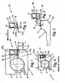
Fig. 1 zeigt demnach ein als Schrägkugellager ausgebildetes Radiallager 15, welches weitgehend wie das an sich bekannte und einleitend beschriebene Radiallager 1 gemäßFig. 5 aufgebaut ist. Bei diesem Radiallager 15 sind daher Kugeln 4 in einem Käfig 5 aufgenommen und zwischen einem Innenring 26 und einem Außenring 3 drehbar angeordnet. Der Innenring 26 weist einen Bord 6 auf, der zur Aufnahme einer Kassettendichtung 20 (durch Presssitz 27a) dient. - Wie insbesondere die
Figuren 2 und 4 verdeutlichen, weist diese Kassettendichtung 20 einen Träger 21 für eine daran befestigte Dichtung 22 auf, die hier dreilippig ausgebildet ist. Zur Kassettendichtung 20 gehört auch ein Winkelblechring 23, mit dem die Kassettendichtung 20 auf dem Innenring 26 durch den Presssitz 27a befestigt wird. - Der Winkelblechring 23 weist einen axialen Schenkel 34 und einen radialen Schenkel 35 auf, an deren zur Dichtung 22 weisenden Innenseiten die Dichtlippen 24 und 25 anliegen. Das freie Ende des radialen Schenkels 35 weist zu einem axial ausgerichteten Abschnitt des Trägers 21, zwischen denen ein nicht näher bezeichneter axialer Spalt ausgebildet ist und welcher axial ausgerichtete Abschnitt des Trägers 21 durch Presssitz 27b am Außenring 3 angeordnet ist.
- Auf der axial anderen Seite des Trägers 21 ist eine an deren radialen Ende vergleichsweise dick ausgebildete elastomere Dichtlippe 33 der Dichtung 22 angeordnet, welche sich radial an dem Außenring 3 abstützt und welche eine statische Abdichtung zum Gehäuse ausbildet (elastomerer Bereich).
- Von besonderer Bedeutung im Zusammenhang mit der Erfindung ist nun die radial in Richtung zum Innenring 26 weisende Dichtlippe 29, die ein radiales Ende 32 hat. Die Dichtlippe 29 weist einen Durchmesser D1 auf, der kleiner ist als der Innendurchmesser D2 des axialen Schenkels 34 des Winkelblechringes 23 bzw, des Presssitzes 27a des Innenringes 26.
- Zudem ist für die Wirkungsweise des Radiallagers 15 auch vorgeshen, dass der Innenring 26 am wälzkörperfernen Ende seines Bords 6 einen ringförmigen Absatz 28 aufweist (
Fig. 3 ). Dieser Absatz ist vergleichsweise klein ausgebildet und hat ein Verhältnis seiner radialen Höhe H zu seiner axialen Breite B von 0,05 zu 1, oder 0,1 zu 1, oder 0,02 zu 1, insbesondere jedoch von 0,15 zu 1. Vorzugsweise ist der Innendurchmesser dieses Absatzes 28 identisch mit dem Durchmesser der Dichtlippe 29. - Wie die Zusammenschau der
Figuren 3 und 4 verdeutlicht, ist der Durchmesser D1 des radialen Endes 32 der Dichtlippe 29, der Durchmessers des axialen Schenkels 34 des Winkelblechringes 23 und die Höhe H bzw. der Innendurchmesser des ringförmigen Absatzes 28 am Innenring 26 so aufeinander abgestimmt, dass bei einem Einführen der Kassettendichtung 20 in den Aufnahmebereich zwischen den Innenring 26 und den Außenring 3 gemäß dem Pfeil 14 das radiale Ende 32 der Dichtlippe 29 in dem ringförmigen Absatzes 28 zunächst unbeschadet aufgenommen wird. - Da die Dichtlippe 29 mit ihrem radialen Ende 32 an der freien Stirnseite des axialen Schenkels 34 des Winkelblechringes 23 anliegt, wird dieses radiale Ende 32 bei einem weiteren Einführen bzw. Einpressen der Kassettendichtung 20 zwischen Innenring 26 und Außenring 3 des Lagers 15 durch den axialen Schenkel 34 des Winkelblechringes 23 abgetrennt und verbleibt als (zusätzliches) statisches Dichtmittel 32 in dem durch den Innenring 26 und dem axialen Schenkel 34 des Winkelblechrings 23 gebildeten ringförmigen Dichtspalt. Hierzu wird auf die Details 30 und 32 in
Fig. 1 hingewiesen. - Das Zusammenwirken der genannten konstruktiven Merkmale des Radiallagers 15 und der Kassettendichtung 20 führt zu einem sehr wirkungsvoll abgedichteten Radiallager, welches hinsichtlich seiner Einzelteile und seiner Montage kostengünstig, beispielsweise als Radlager für Kraftfahrzeuge herstellbar ist.
- Die Erfindung betrifft die Kassettendichtung 20 an sich, welche ein Produkt sein kann, das ein Lagerhersteller als Zulieferteil von einem anderen Hersteller beziehen kann. Diese Kassettendichtung 20 weist insbesondere einen Träger 21, eine an dem Träger 21 befestigte Dichtung 22 mit einer Dichtlippe 29 und einen Winkelblechring 23 auf, wobei die Dichtlippe 29 im Wesentlichen radial nach Innen in Richtung zu der Aufnahmeöffnung für einen Lagerring 26 weist und einen Durchmesser D1 hat, der kleiner ist als der Innendurchmesser D2 eines axialen Schenkels 34 des Winkelblechringes 23. Die Dichtlippe 29 liegt dabei nicht auf dem axialen Schenkel 34 auf, sondern vorzugsweise an dessen stirnseitigem Ende an.
- Shließlich betrifft die Erfindung auch ein Verfahren zur Montage einer solchen Kassettendichtung in einem Radiallager.
-
- 1
- Radiallager, Schrägkugellager
- 2
- Innenring
- 3
- Außenring
- 4
- Wälzkörper, Kugel
- 5
- Käfig
- 6
- Bord am Innenring
- 7
- Absatz am Außenring
- 8
- Wälzkörperlaufbahn
- 9
- Wälzkörperlaufbahn
- 10
- Kassettendichtung
- 11
- Träger
- 12
- Dichtung
- 13
- Winkelblechring
- 14
- Pfeil, Montagerichtung
- 15
- Radiallager mit Kassettendichtung gemäß der Erfindung
- 20
- Kassettendichtung
- 21
- Träger
- 22
- Dichtung
- 23
- Winkelblechring
- 24
- Dichtlippe
- 25
- Dichtlippe
- 26
- Innenring
- 27a
- Presssitz am Innenring bzw. im Bereich der Welle
- 27b
- Presssitz am Außenring bzw. im Bereich des Gehäuses
- 28
- Ringförmiger Absatz
- 29
- Dichtlippe (für zusätzliche statische Abdichtung)
- 30
- Detail
- 31
- Detail
- 32
- Radiales Ende der Dichtlippe 29; Dichtmittel
- 33
- statische Abdichtung, elastomerer Bereich
- 34
- Axialer Schenkel des Winkelblechrings
- 35
- Radialer Schenkel des Winkelblechrings
- B
- Breite des Absatzes
- H
- Höhe des Absatzes
- D1
- Durchmesser der Dichtlippe 29; Innendurchmesser des Absatzes 28
- D2
- Durchmesser des Presssitzes; Innendurchmesser des Winkelblechrings
Claims (8)
- Kassettendichtung (20) für ein Radiallager (15), mit einem Träger (21) und mit einer an dem Träger befestigten Dichtung (22), sowie mit einer an der Dichtung (22) ausgebildeten Dichtlippe (29) und mit einem Winkelblechring (23), wobei die Dichtlippe (29) im Wesentlichen radial nach innen weist und einen Durchmesser (D1) hat, der kleiner ist als der Innendurchmesser (D2) eines axialen Schenkels (34) des Winkelblechringes (23), sowie radial nicht auf dem axialen Schenkel (34) aufliegt, dadurch gekennzeichnet, dass die Dichtlippe (29) mit einem radialen Ende (32) an der Stirnseite des axialen Schenkels (34) des Winkelbleches (23) anliegt.
- Radiallager (15) mit einer Kassettendichtung (20) nach Anspruch 1, bei dem das Radiallager (15) einen Innenring (26) und einen Außenring (3) sowie dazwischen angeordnete Wälzkörper (4) aufweist, und bei dem die Kassettendichtung (20) axial neben den Wälzkörpern (4) zwischen dem Innenring (26) und dem Außenring (3) in einem Presssitz angeordnet ist, wobei zwischen dem Winkelblechring (23) und dem Lagerring (26) ein Dichtmittel (32) angeordnet ist.
- Radiallager nach Anspruch 2, dadurch gekennzeichnet, dass das Dichtmittel (32) in einem mit dem Winkelblechring (23) zusammenwirkenden ringförmigen radialen Absatz (28) im Lagerring, insbesondere im Lagerinnenring (26), angeordnet ist.
- Radiallager nach wenigstens einem der Ansprüche 1 bis 3, dadurch gekennzeichnet, dass die Dichtung (22) dreilippig (24, 25, 29) ausgebildet ist, mit der Dichtlippe (29), mit einer an der Innenseite eines radialen Schenkels (35) des Winkelblechringes (23) anliegenden Dichtlippe (24), und mit einer an der Innenseite des axialen Schenkels (34) des Winkelblechringes (23) anliegenden Dichtlippe (25).
- Radiallager nach wenigstens einem der Ansprüche 1 bis 3, dadurch gekennzeichnet, dass an dem Träger (11) eine weitere Dichtlippe (33), insbesondere zur statischen Abdichtung am Gehäuse, angeordnet ist, die am jeweils zugeordneten Lagerring, insbesondere am Lageraußenring (3) radial anliegt.
- Radiallager nach wenigstens einem der Ansprüche 1 bis 5, dadurch gekennzeichnet, dass der ringförmige Absatz (28) ein Verhältnis von radialer Höhe (H) zu axialer Breite (B) im Bereich von 0,05 zu 1, oder 0,1 zu 1 oder 0,02 zu 1, insbesondere jedoch 0,15 zu 1 aufweist.
- Radiallager nach wenigstens einem der Ansprüche 1 bis 8, dadurch gekennzeichnet, dass der Lagerring als Innenring (26) oder als Außenring (3) ausgebildet ist.
- Montage einer Kassettendichtung (20) in einem Radiallager (15), wobei die Kassettendichtung (20) einen Träger (21) und eine an dem Träger befestigte Dichtung (22) aufweist, sowie mit einer an der Dichtung (22) ausgebildeten Dichtlippe (29) und mit einem Winkelblechring (23) versehen ist, wobei die Dichtlippe (29) im Wesentlichen radial nach innen weist und einen Durchmesser (D1) aufweist, der kleiner ist als der Innendurchmesser (D2) eines axialen Schenkels (34) des Winkelblechrings (23), wobei die Dichtlippe (29) radial nicht auf dem axialen Schenkel (34) aufliegt, sondern mit einem radialen Ende an der Stirnseite des axialen Schenkels des Winkelblechs anliegt, wobei das Radiallager (15) einen Innenring (26) und einen Außenring (3), sowie dazwischen angeordnete Wälzkörper (4) aufweist, wobei die Kassettendichtung (20) axial neben den Wälzkörpern (4) zwischen dem Innenring (26) und dem Außenring (3) in einem Presssitz angeordnet wird und zwischen dem Winkelblechring (23) und dem Lagerring (26) ein Dichtmittel (32) angeordnet wird, dadurch gekennzeichnet, dass das Dichtmittel (32) durch ein bei der Montage der Kassettendichtung (20) in das Radiallager (15) abgetrenntes radiales Ende der Dichtlippe (29) der Dichtung (22) gebildet wird.
Applications Claiming Priority (2)
| Application Number | Priority Date | Filing Date | Title |
|---|---|---|---|
| DE102005061168A DE102005061168A1 (de) | 2005-12-21 | 2005-12-21 | Radiallager mit einer Kassettendichtung, sowie Kassettendichtung |
| PCT/DE2006/002186 WO2007071230A1 (de) | 2005-12-21 | 2006-12-08 | Radiallager mit einer kassettendichtung, sowie kassettendichtung |
Publications (2)
| Publication Number | Publication Date |
|---|---|
| EP1963697A1 EP1963697A1 (de) | 2008-09-03 |
| EP1963697B1 true EP1963697B1 (de) | 2014-11-26 |
Family
ID=37767435
Family Applications (1)
| Application Number | Title | Priority Date | Filing Date |
|---|---|---|---|
| EP06818121.3A Not-in-force EP1963697B1 (de) | 2005-12-21 | 2006-12-08 | Radiallager mit einer kassettendichtung, sowie kassettendichtung |
Country Status (6)
| Country | Link |
|---|---|
| US (1) | US20080310782A1 (de) |
| EP (1) | EP1963697B1 (de) |
| JP (1) | JP2009520935A (de) |
| KR (1) | KR20080078037A (de) |
| DE (1) | DE102005061168A1 (de) |
| WO (1) | WO2007071230A1 (de) |
Cited By (1)
| Publication number | Priority date | Publication date | Assignee | Title |
|---|---|---|---|---|
| WO2019110035A1 (de) | 2017-12-07 | 2019-06-13 | Schaeffler Technologies AG & Co. KG | Abgedichtetes wälzlager und verfahren zum betrieb eines wälzlagers |
Families Citing this family (11)
| Publication number | Priority date | Publication date | Assignee | Title |
|---|---|---|---|---|
| DE102008057056A1 (de) * | 2008-11-13 | 2010-05-20 | Schaeffler Kg | Dichtungsanordnung mit radiale Dichtlippe |
| JP5480369B2 (ja) * | 2009-05-25 | 2014-04-23 | アクティエボラゲット・エスコーエッフ | 特に農業用途で利用するための軸受シール組立体 |
| CN102239341B (zh) * | 2010-01-13 | 2014-07-02 | 日本精工株式会社 | 带组合密封环的滚动轴承单元 |
| EP2685117B1 (de) * | 2011-03-09 | 2019-12-25 | NTN Corporation | Radnabe-wälzlager-anordnung mit einem signalgeber und einer dichtkappe für das rad eines fahrzeugs |
| DE102011077536A1 (de) | 2011-06-15 | 2012-12-20 | Schaeffler Technologies AG & Co. KG | Statische Abdichtung mit Verfahren zur Abdichtung |
| JP5969267B2 (ja) | 2012-05-24 | 2016-08-17 | Ntn株式会社 | 外輪回転用軸受 |
| JP6241188B2 (ja) * | 2013-10-16 | 2017-12-06 | 日本精工株式会社 | エンコーダ付組み合わせシールリング及びエンコーダ付転がり軸受ユニット |
| DE102014220584A1 (de) | 2014-10-10 | 2016-04-14 | Schaeffler Technologies AG & Co. KG | Dichtungsanordnung, abgedichtete Maschinenelementanordnung sowie Wälzlager mit abgedichtetem Wälzkörperraum |
| US10415642B2 (en) * | 2015-06-09 | 2019-09-17 | Aktiebolaget Skf | Coupling system of a sealing assembly with a rotating annular element |
| DE102017101492A1 (de) | 2017-01-26 | 2018-07-26 | Schaeffler Technologies AG & Co. KG | Dichtungsanordnung einer Wälzlagerung mit vorgespannten statischen Dichtsitzen |
| KR102165746B1 (ko) | 2019-05-30 | 2020-10-15 | 셰플러코리아(유) | 이물 침입 저항성이 향상된 구름 베어링 |
Family Cites Families (7)
| Publication number | Priority date | Publication date | Assignee | Title |
|---|---|---|---|---|
| DE3806928A1 (de) * | 1988-03-03 | 1989-09-14 | Kugelfischer G Schaefer & Co | Dichtung, insbesondere fuer waelzlager |
| IT239743Y1 (it) * | 1996-05-17 | 2001-03-13 | Skf Ind Spa | Sistema di tenuta per organi meccnici accoppiati in rotazionerelativa. |
| IT1294864B1 (it) * | 1997-09-12 | 1999-04-23 | Skf Ind Spa | Complesso di tenuta per un cuscinetto di rotolamento. |
| US6367811B1 (en) * | 1998-11-24 | 2002-04-09 | Mitsubishi Cable Industries, Ltd. | Rotation shaft seal |
| DE19916934B4 (de) * | 1999-04-15 | 2009-04-09 | Schaeffler Kg | Kassettendichtung für Wälzlager |
| US6637754B1 (en) * | 1999-11-17 | 2003-10-28 | Ntn Corporation | Wheel bearing and sealing device therefor |
| JP4503237B2 (ja) * | 2003-04-04 | 2010-07-14 | 内山工業株式会社 | 組合せシール及び軸受ユニット |
-
2005
- 2005-12-21 DE DE102005061168A patent/DE102005061168A1/de not_active Withdrawn
-
2006
- 2006-12-08 KR KR1020087016152A patent/KR20080078037A/ko not_active Application Discontinuation
- 2006-12-08 WO PCT/DE2006/002186 patent/WO2007071230A1/de active Application Filing
- 2006-12-08 US US12/158,349 patent/US20080310782A1/en not_active Abandoned
- 2006-12-08 EP EP06818121.3A patent/EP1963697B1/de not_active Not-in-force
- 2006-12-08 JP JP2008549754A patent/JP2009520935A/ja active Pending
Cited By (1)
| Publication number | Priority date | Publication date | Assignee | Title |
|---|---|---|---|---|
| WO2019110035A1 (de) | 2017-12-07 | 2019-06-13 | Schaeffler Technologies AG & Co. KG | Abgedichtetes wälzlager und verfahren zum betrieb eines wälzlagers |
Also Published As
| Publication number | Publication date |
|---|---|
| KR20080078037A (ko) | 2008-08-26 |
| DE102005061168A1 (de) | 2007-08-09 |
| WO2007071230A1 (de) | 2007-06-28 |
| US20080310782A1 (en) | 2008-12-18 |
| EP1963697A1 (de) | 2008-09-03 |
| JP2009520935A (ja) | 2009-05-28 |
Similar Documents
| Publication | Publication Date | Title |
|---|---|---|
| EP1963697B1 (de) | Radiallager mit einer kassettendichtung, sowie kassettendichtung | |
| EP2459891B1 (de) | Wälzlageranordnung mit einem radialwellendichtring | |
| EP2603708A1 (de) | Dichtungsanordnung für wälzlager | |
| WO2013160015A1 (de) | Vormontiert einpressbare wälzlagereinheit | |
| WO2019158151A1 (de) | Radlageranordnung mit einer rotationsachse | |
| DE102014215000B4 (de) | Dichtung für ein Wälzlager, Kreuzgelenk und Lagerbüchse mit der Dichtung | |
| EP2280202B1 (de) | Dichtungsanordnung für eine Radlagerung eines Kraftfahrzeuges | |
| WO2018192597A1 (de) | Dichtungsanordnung eines radlagers | |
| DE102010015200A1 (de) | Kasettendichtung | |
| WO2002044578A1 (de) | Abdichtung für ein ausrücklager | |
| WO2011006840A1 (de) | Kompakte axial-radial-lagerung | |
| DE112005000496T5 (de) | Nabeneinheit für ein Rad | |
| DE102016212127A1 (de) | Dichtungsanordnung mit Dichtungsring sowie Maschinenelementanordnung | |
| DE102016211196A1 (de) | Wälzlagereinheit | |
| EP1736676B1 (de) | Wälzlager mit einem Dichtelement | |
| EP3810943A1 (de) | Wälzlager und dichtungsanordnung mit mindestens zwei dichtlippen | |
| EP2325509B1 (de) | Wälzlager mit aus blech hergestellten lagerringen | |
| DE102015218625A1 (de) | Dichtung für eine Radlageranordnung | |
| DE102015218865A1 (de) | Lageranordnung | |
| WO2011064126A2 (de) | Kassettendichtung für radiallager und installationsverfahren | |
| DE102009019396B4 (de) | Dichtungsanordnung für eine Wälzlagerung | |
| DE102010041611B4 (de) | Radial-Wellendichtring | |
| EP1477694B1 (de) | Dichtungsanordnung zur Abdichtung eines Spalts zwischen einer Lagerbüchse und einem Zapfen | |
| DE102015218629A1 (de) | Dichtungsanordnung für Radlager | |
| DE102009057112A1 (de) | Abgedichtetes, einreihiges Schrägrollenlager |
Legal Events
| Date | Code | Title | Description |
|---|---|---|---|
| PUAI | Public reference made under article 153(3) epc to a published international application that has entered the european phase |
Free format text: ORIGINAL CODE: 0009012 |
|
| 17P | Request for examination filed |
Effective date: 20080604 |
|
| AK | Designated contracting states |
Kind code of ref document: A1 Designated state(s): AT BE BG CH CY CZ DE DK EE ES FI FR GB GR HU IE IS IT LI LT LU LV MC NL PL PT RO SE SI SK TR |
|
| 17Q | First examination report despatched |
Effective date: 20100216 |
|
| RAP1 | Party data changed (applicant data changed or rights of an application transferred) |
Owner name: SCHAEFFLER TECHNOLOGIES AG & CO. KG |
|
| DAX | Request for extension of the european patent (deleted) | ||
| GRAP | Despatch of communication of intention to grant a patent |
Free format text: ORIGINAL CODE: EPIDOSNIGR1 |
|
| RAP1 | Party data changed (applicant data changed or rights of an application transferred) |
Owner name: SCHAEFFLER TECHNOLOGIES GMBH & CO. KG |
|
| INTG | Intention to grant announced |
Effective date: 20140226 |
|
| GRAS | Grant fee paid |
Free format text: ORIGINAL CODE: EPIDOSNIGR3 |
|
| GRAP | Despatch of communication of intention to grant a patent |
Free format text: ORIGINAL CODE: EPIDOSNIGR1 |
|
| INTG | Intention to grant announced |
Effective date: 20140923 |
|
| GRAA | (expected) grant |
Free format text: ORIGINAL CODE: 0009210 |
|
| AK | Designated contracting states |
Kind code of ref document: B1 Designated state(s): AT BE BG CH CY CZ DE DK EE ES FI FR GB GR HU IE IS IT LI LT LU LV MC NL PL PT RO SE SI SK TR |
|
| REG | Reference to a national code |
Ref country code: GB Ref legal event code: FG4D Free format text: NOT ENGLISH |
|
| REG | Reference to a national code |
Ref country code: CH Ref legal event code: EP |
|
| REG | Reference to a national code |
Ref country code: AT Ref legal event code: REF Ref document number: 698390 Country of ref document: AT Kind code of ref document: T Effective date: 20141215 |
|
| REG | Reference to a national code |
Ref country code: IE Ref legal event code: FG4D Free format text: LANGUAGE OF EP DOCUMENT: GERMAN |
|
| REG | Reference to a national code |
Ref country code: DE Ref legal event code: R096 Ref document number: 502006014094 Country of ref document: DE Effective date: 20150108 |
|
| RAP2 | Party data changed (patent owner data changed or rights of a patent transferred) |
Owner name: SCHAEFFLER TECHNOLOGIES AG & CO. KG |
|
| REG | Reference to a national code |
Ref country code: DE Ref legal event code: R081 Ref document number: 502006014094 Country of ref document: DE Owner name: SCHAEFFLER TECHNOLOGIES AG & CO. KG, DE Free format text: FORMER OWNER: SCHAEFFLER TECHNOLOGIES GMBH & CO. KG, 91074 HERZOGENAURACH, DE Effective date: 20150122 |
|
| REG | Reference to a national code |
Ref country code: NL Ref legal event code: VDEP Effective date: 20141126 |
|
| REG | Reference to a national code |
Ref country code: LT Ref legal event code: MG4D |
|
| PG25 | Lapsed in a contracting state [announced via postgrant information from national office to epo] |
Ref country code: LT Free format text: LAPSE BECAUSE OF FAILURE TO SUBMIT A TRANSLATION OF THE DESCRIPTION OR TO PAY THE FEE WITHIN THE PRESCRIBED TIME-LIMIT Effective date: 20141126 Ref country code: FI Free format text: LAPSE BECAUSE OF FAILURE TO SUBMIT A TRANSLATION OF THE DESCRIPTION OR TO PAY THE FEE WITHIN THE PRESCRIBED TIME-LIMIT Effective date: 20141126 Ref country code: IS Free format text: LAPSE BECAUSE OF FAILURE TO SUBMIT A TRANSLATION OF THE DESCRIPTION OR TO PAY THE FEE WITHIN THE PRESCRIBED TIME-LIMIT Effective date: 20150326 Ref country code: ES Free format text: LAPSE BECAUSE OF FAILURE TO SUBMIT A TRANSLATION OF THE DESCRIPTION OR TO PAY THE FEE WITHIN THE PRESCRIBED TIME-LIMIT Effective date: 20141126 Ref country code: NL Free format text: LAPSE BECAUSE OF FAILURE TO SUBMIT A TRANSLATION OF THE DESCRIPTION OR TO PAY THE FEE WITHIN THE PRESCRIBED TIME-LIMIT Effective date: 20141126 Ref country code: PT Free format text: LAPSE BECAUSE OF FAILURE TO SUBMIT A TRANSLATION OF THE DESCRIPTION OR TO PAY THE FEE WITHIN THE PRESCRIBED TIME-LIMIT Effective date: 20150326 |
|
| PG25 | Lapsed in a contracting state [announced via postgrant information from national office to epo] |
Ref country code: GR Free format text: LAPSE BECAUSE OF FAILURE TO SUBMIT A TRANSLATION OF THE DESCRIPTION OR TO PAY THE FEE WITHIN THE PRESCRIBED TIME-LIMIT Effective date: 20150227 Ref country code: LV Free format text: LAPSE BECAUSE OF FAILURE TO SUBMIT A TRANSLATION OF THE DESCRIPTION OR TO PAY THE FEE WITHIN THE PRESCRIBED TIME-LIMIT Effective date: 20141126 Ref country code: SE Free format text: LAPSE BECAUSE OF FAILURE TO SUBMIT A TRANSLATION OF THE DESCRIPTION OR TO PAY THE FEE WITHIN THE PRESCRIBED TIME-LIMIT Effective date: 20141126 Ref country code: CY Free format text: LAPSE BECAUSE OF FAILURE TO SUBMIT A TRANSLATION OF THE DESCRIPTION OR TO PAY THE FEE WITHIN THE PRESCRIBED TIME-LIMIT Effective date: 20141126 |
|
| PG25 | Lapsed in a contracting state [announced via postgrant information from national office to epo] |
Ref country code: BE Free format text: LAPSE BECAUSE OF NON-PAYMENT OF DUE FEES Effective date: 20141231 |
|
| PG25 | Lapsed in a contracting state [announced via postgrant information from national office to epo] |
Ref country code: SK Free format text: LAPSE BECAUSE OF FAILURE TO SUBMIT A TRANSLATION OF THE DESCRIPTION OR TO PAY THE FEE WITHIN THE PRESCRIBED TIME-LIMIT Effective date: 20141126 Ref country code: CZ Free format text: LAPSE BECAUSE OF FAILURE TO SUBMIT A TRANSLATION OF THE DESCRIPTION OR TO PAY THE FEE WITHIN THE PRESCRIBED TIME-LIMIT Effective date: 20141126 Ref country code: EE Free format text: LAPSE BECAUSE OF FAILURE TO SUBMIT A TRANSLATION OF THE DESCRIPTION OR TO PAY THE FEE WITHIN THE PRESCRIBED TIME-LIMIT Effective date: 20141126 Ref country code: DK Free format text: LAPSE BECAUSE OF FAILURE TO SUBMIT A TRANSLATION OF THE DESCRIPTION OR TO PAY THE FEE WITHIN THE PRESCRIBED TIME-LIMIT Effective date: 20141126 Ref country code: RO Free format text: LAPSE BECAUSE OF FAILURE TO SUBMIT A TRANSLATION OF THE DESCRIPTION OR TO PAY THE FEE WITHIN THE PRESCRIBED TIME-LIMIT Effective date: 20141126 |
|
| REG | Reference to a national code |
Ref country code: CH Ref legal event code: PL |
|
| REG | Reference to a national code |
Ref country code: DE Ref legal event code: R097 Ref document number: 502006014094 Country of ref document: DE |
|
| PG25 | Lapsed in a contracting state [announced via postgrant information from national office to epo] |
Ref country code: PL Free format text: LAPSE BECAUSE OF FAILURE TO SUBMIT A TRANSLATION OF THE DESCRIPTION OR TO PAY THE FEE WITHIN THE PRESCRIBED TIME-LIMIT Effective date: 20141126 Ref country code: MC Free format text: LAPSE BECAUSE OF FAILURE TO SUBMIT A TRANSLATION OF THE DESCRIPTION OR TO PAY THE FEE WITHIN THE PRESCRIBED TIME-LIMIT Effective date: 20141126 |
|
| REG | Reference to a national code |
Ref country code: IE Ref legal event code: MM4A |
|
| PLBE | No opposition filed within time limit |
Free format text: ORIGINAL CODE: 0009261 |
|
| STAA | Information on the status of an ep patent application or granted ep patent |
Free format text: STATUS: NO OPPOSITION FILED WITHIN TIME LIMIT |
|
| PG25 | Lapsed in a contracting state [announced via postgrant information from national office to epo] |
Ref country code: IE Free format text: LAPSE BECAUSE OF NON-PAYMENT OF DUE FEES Effective date: 20141208 Ref country code: CH Free format text: LAPSE BECAUSE OF NON-PAYMENT OF DUE FEES Effective date: 20141231 Ref country code: LI Free format text: LAPSE BECAUSE OF NON-PAYMENT OF DUE FEES Effective date: 20141231 |
|
| 26N | No opposition filed |
Effective date: 20150827 |
|
| REG | Reference to a national code |
Ref country code: FR Ref legal event code: PLFP Year of fee payment: 10 |
|
| PG25 | Lapsed in a contracting state [announced via postgrant information from national office to epo] |
Ref country code: IT Free format text: LAPSE BECAUSE OF FAILURE TO SUBMIT A TRANSLATION OF THE DESCRIPTION OR TO PAY THE FEE WITHIN THE PRESCRIBED TIME-LIMIT Effective date: 20141126 |
|
| REG | Reference to a national code |
Ref country code: AT Ref legal event code: MM01 Ref document number: 698390 Country of ref document: AT Kind code of ref document: T Effective date: 20141208 |
|
| PG25 | Lapsed in a contracting state [announced via postgrant information from national office to epo] |
Ref country code: SI Free format text: LAPSE BECAUSE OF FAILURE TO SUBMIT A TRANSLATION OF THE DESCRIPTION OR TO PAY THE FEE WITHIN THE PRESCRIBED TIME-LIMIT Effective date: 20141126 |
|
| PG25 | Lapsed in a contracting state [announced via postgrant information from national office to epo] |
Ref country code: BG Free format text: LAPSE BECAUSE OF FAILURE TO SUBMIT A TRANSLATION OF THE DESCRIPTION OR TO PAY THE FEE WITHIN THE PRESCRIBED TIME-LIMIT Effective date: 20141126 Ref country code: AT Free format text: LAPSE BECAUSE OF NON-PAYMENT OF DUE FEES Effective date: 20141208 |
|
| PG25 | Lapsed in a contracting state [announced via postgrant information from national office to epo] |
Ref country code: HU Free format text: LAPSE BECAUSE OF FAILURE TO SUBMIT A TRANSLATION OF THE DESCRIPTION OR TO PAY THE FEE WITHIN THE PRESCRIBED TIME-LIMIT; INVALID AB INITIO Effective date: 20061208 Ref country code: LU Free format text: LAPSE BECAUSE OF NON-PAYMENT OF DUE FEES Effective date: 20141208 Ref country code: TR Free format text: LAPSE BECAUSE OF FAILURE TO SUBMIT A TRANSLATION OF THE DESCRIPTION OR TO PAY THE FEE WITHIN THE PRESCRIBED TIME-LIMIT Effective date: 20141126 |
|
| REG | Reference to a national code |
Ref country code: FR Ref legal event code: PLFP Year of fee payment: 11 |
|
| PGFP | Annual fee paid to national office [announced via postgrant information from national office to epo] |
Ref country code: GB Payment date: 20161228 Year of fee payment: 11 |
|
| PGFP | Annual fee paid to national office [announced via postgrant information from national office to epo] |
Ref country code: FR Payment date: 20161229 Year of fee payment: 11 |
|
| PGFP | Annual fee paid to national office [announced via postgrant information from national office to epo] |
Ref country code: DE Payment date: 20170228 Year of fee payment: 11 |
|
| REG | Reference to a national code |
Ref country code: DE Ref legal event code: R119 Ref document number: 502006014094 Country of ref document: DE |
|
| GBPC | Gb: european patent ceased through non-payment of renewal fee |
Effective date: 20171208 |
|
| REG | Reference to a national code |
Ref country code: FR Ref legal event code: ST Effective date: 20180831 |
|
| PG25 | Lapsed in a contracting state [announced via postgrant information from national office to epo] |
Ref country code: FR Free format text: LAPSE BECAUSE OF NON-PAYMENT OF DUE FEES Effective date: 20180102 Ref country code: DE Free format text: LAPSE BECAUSE OF NON-PAYMENT OF DUE FEES Effective date: 20180703 |
|
| PG25 | Lapsed in a contracting state [announced via postgrant information from national office to epo] |
Ref country code: GB Free format text: LAPSE BECAUSE OF NON-PAYMENT OF DUE FEES Effective date: 20171208 |
|
| P01 | Opt-out of the competence of the unified patent court (upc) registered |
Effective date: 20230523 |