EP1963697B1 - Palier radial dote d'un joint d'étanchéité a cassette et joint d'étanchéité à cassette - Google Patents
Palier radial dote d'un joint d'étanchéité a cassette et joint d'étanchéité à cassette Download PDFInfo
- Publication number
- EP1963697B1 EP1963697B1 EP06818121.3A EP06818121A EP1963697B1 EP 1963697 B1 EP1963697 B1 EP 1963697B1 EP 06818121 A EP06818121 A EP 06818121A EP 1963697 B1 EP1963697 B1 EP 1963697B1
- Authority
- EP
- European Patent Office
- Prior art keywords
- ring
- bearing
- seal
- radial
- sealing lip
- Prior art date
- Legal status (The legal status is an assumption and is not a legal conclusion. Google has not performed a legal analysis and makes no representation as to the accuracy of the status listed.)
- Not-in-force
Links
Images
Classifications
-
- F—MECHANICAL ENGINEERING; LIGHTING; HEATING; WEAPONS; BLASTING
- F16—ENGINEERING ELEMENTS AND UNITS; GENERAL MEASURES FOR PRODUCING AND MAINTAINING EFFECTIVE FUNCTIONING OF MACHINES OR INSTALLATIONS; THERMAL INSULATION IN GENERAL
- F16C—SHAFTS; FLEXIBLE SHAFTS; ELEMENTS OR CRANKSHAFT MECHANISMS; ROTARY BODIES OTHER THAN GEARING ELEMENTS; BEARINGS
- F16C33/00—Parts of bearings; Special methods for making bearings or parts thereof
- F16C33/72—Sealings
-
- F—MECHANICAL ENGINEERING; LIGHTING; HEATING; WEAPONS; BLASTING
- F16—ENGINEERING ELEMENTS AND UNITS; GENERAL MEASURES FOR PRODUCING AND MAINTAINING EFFECTIVE FUNCTIONING OF MACHINES OR INSTALLATIONS; THERMAL INSULATION IN GENERAL
- F16J—PISTONS; CYLINDERS; SEALINGS
- F16J15/00—Sealings
- F16J15/16—Sealings between relatively-moving surfaces
- F16J15/32—Sealings between relatively-moving surfaces with elastic sealings, e.g. O-rings
- F16J15/3248—Sealings between relatively-moving surfaces with elastic sealings, e.g. O-rings provided with casings or supports
- F16J15/3252—Sealings between relatively-moving surfaces with elastic sealings, e.g. O-rings provided with casings or supports with rigid casings or supports
- F16J15/3256—Sealings between relatively-moving surfaces with elastic sealings, e.g. O-rings provided with casings or supports with rigid casings or supports comprising two casing or support elements, one attached to each surface, e.g. cartridge or cassette seals
- F16J15/3264—Sealings between relatively-moving surfaces with elastic sealings, e.g. O-rings provided with casings or supports with rigid casings or supports comprising two casing or support elements, one attached to each surface, e.g. cartridge or cassette seals the elements being separable from each other
-
- F—MECHANICAL ENGINEERING; LIGHTING; HEATING; WEAPONS; BLASTING
- F16—ENGINEERING ELEMENTS AND UNITS; GENERAL MEASURES FOR PRODUCING AND MAINTAINING EFFECTIVE FUNCTIONING OF MACHINES OR INSTALLATIONS; THERMAL INSULATION IN GENERAL
- F16C—SHAFTS; FLEXIBLE SHAFTS; ELEMENTS OR CRANKSHAFT MECHANISMS; ROTARY BODIES OTHER THAN GEARING ELEMENTS; BEARINGS
- F16C33/00—Parts of bearings; Special methods for making bearings or parts thereof
- F16C33/72—Sealings
- F16C33/76—Sealings of ball or roller bearings
- F16C33/78—Sealings of ball or roller bearings with a diaphragm, disc, or ring, with or without resilient members
- F16C33/7816—Details of the sealing or parts thereof, e.g. geometry, material
- F16C33/782—Details of the sealing or parts thereof, e.g. geometry, material of the sealing region
-
- F—MECHANICAL ENGINEERING; LIGHTING; HEATING; WEAPONS; BLASTING
- F16—ENGINEERING ELEMENTS AND UNITS; GENERAL MEASURES FOR PRODUCING AND MAINTAINING EFFECTIVE FUNCTIONING OF MACHINES OR INSTALLATIONS; THERMAL INSULATION IN GENERAL
- F16C—SHAFTS; FLEXIBLE SHAFTS; ELEMENTS OR CRANKSHAFT MECHANISMS; ROTARY BODIES OTHER THAN GEARING ELEMENTS; BEARINGS
- F16C33/00—Parts of bearings; Special methods for making bearings or parts thereof
- F16C33/72—Sealings
- F16C33/76—Sealings of ball or roller bearings
- F16C33/78—Sealings of ball or roller bearings with a diaphragm, disc, or ring, with or without resilient members
- F16C33/7869—Sealings of ball or roller bearings with a diaphragm, disc, or ring, with or without resilient members mounted with a cylindrical portion to the inner surface of the outer race and having a radial portion extending inward
- F16C33/7879—Sealings of ball or roller bearings with a diaphragm, disc, or ring, with or without resilient members mounted with a cylindrical portion to the inner surface of the outer race and having a radial portion extending inward with a further sealing ring
- F16C33/7883—Sealings of ball or roller bearings with a diaphragm, disc, or ring, with or without resilient members mounted with a cylindrical portion to the inner surface of the outer race and having a radial portion extending inward with a further sealing ring mounted to the inner race and of generally L-shape, the two sealing rings defining a sealing with box-shaped cross-section
-
- F—MECHANICAL ENGINEERING; LIGHTING; HEATING; WEAPONS; BLASTING
- F16—ENGINEERING ELEMENTS AND UNITS; GENERAL MEASURES FOR PRODUCING AND MAINTAINING EFFECTIVE FUNCTIONING OF MACHINES OR INSTALLATIONS; THERMAL INSULATION IN GENERAL
- F16C—SHAFTS; FLEXIBLE SHAFTS; ELEMENTS OR CRANKSHAFT MECHANISMS; ROTARY BODIES OTHER THAN GEARING ELEMENTS; BEARINGS
- F16C43/00—Assembling bearings
- F16C43/04—Assembling rolling-contact bearings
- F16C43/045—Mounting or replacing seals
-
- F—MECHANICAL ENGINEERING; LIGHTING; HEATING; WEAPONS; BLASTING
- F16—ENGINEERING ELEMENTS AND UNITS; GENERAL MEASURES FOR PRODUCING AND MAINTAINING EFFECTIVE FUNCTIONING OF MACHINES OR INSTALLATIONS; THERMAL INSULATION IN GENERAL
- F16J—PISTONS; CYLINDERS; SEALINGS
- F16J15/00—Sealings
- F16J15/16—Sealings between relatively-moving surfaces
- F16J15/32—Sealings between relatively-moving surfaces with elastic sealings, e.g. O-rings
-
- F—MECHANICAL ENGINEERING; LIGHTING; HEATING; WEAPONS; BLASTING
- F16—ENGINEERING ELEMENTS AND UNITS; GENERAL MEASURES FOR PRODUCING AND MAINTAINING EFFECTIVE FUNCTIONING OF MACHINES OR INSTALLATIONS; THERMAL INSULATION IN GENERAL
- F16C—SHAFTS; FLEXIBLE SHAFTS; ELEMENTS OR CRANKSHAFT MECHANISMS; ROTARY BODIES OTHER THAN GEARING ELEMENTS; BEARINGS
- F16C19/00—Bearings with rolling contact, for exclusively rotary movement
- F16C19/02—Bearings with rolling contact, for exclusively rotary movement with bearing balls essentially of the same size in one or more circular rows
- F16C19/14—Bearings with rolling contact, for exclusively rotary movement with bearing balls essentially of the same size in one or more circular rows for both radial and axial load
- F16C19/18—Bearings with rolling contact, for exclusively rotary movement with bearing balls essentially of the same size in one or more circular rows for both radial and axial load with two or more rows of balls
- F16C19/181—Bearings with rolling contact, for exclusively rotary movement with bearing balls essentially of the same size in one or more circular rows for both radial and axial load with two or more rows of balls with angular contact
- F16C19/183—Bearings with rolling contact, for exclusively rotary movement with bearing balls essentially of the same size in one or more circular rows for both radial and axial load with two or more rows of balls with angular contact with two rows at opposite angles
- F16C19/184—Bearings with rolling contact, for exclusively rotary movement with bearing balls essentially of the same size in one or more circular rows for both radial and axial load with two or more rows of balls with angular contact with two rows at opposite angles in O-arrangement
-
- F—MECHANICAL ENGINEERING; LIGHTING; HEATING; WEAPONS; BLASTING
- F16—ENGINEERING ELEMENTS AND UNITS; GENERAL MEASURES FOR PRODUCING AND MAINTAINING EFFECTIVE FUNCTIONING OF MACHINES OR INSTALLATIONS; THERMAL INSULATION IN GENERAL
- F16C—SHAFTS; FLEXIBLE SHAFTS; ELEMENTS OR CRANKSHAFT MECHANISMS; ROTARY BODIES OTHER THAN GEARING ELEMENTS; BEARINGS
- F16C2326/00—Articles relating to transporting
- F16C2326/01—Parts of vehicles in general
- F16C2326/02—Wheel hubs or castors
Definitions
- the invention relates to a cartridge seal for a radial bearing, wherein the radial bearing has an inner ring and an outer ring and arranged therebetween rolling elements, and wherein the cartridge seal is disposed axially adjacent to the rolling elements between the inner ring and the outer ring in a press fit, wherein the cartridge seal a support , An attached thereto seal and an angle sheet ring, abut the sealing lips of the seal.
- the invention relates to a method for mounting such a cassette seal in a radial bearing.
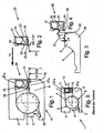
- Fig. 5 illustrated on a trained as angular contact ball bearing 1 bearing the camp itself and the there inserted into a press fit on the shaft and on the housing bore cassette seal 10th
- the angular contact ball bearing 1 consists essentially of an inner ring 2 and an outer ring 3, between which e.g. formed as balls 4 rolling elements in raceways 8 and 9 are arranged to be movable.
- the balls 4 are received in a cage 5, which is snapped on the inner ring 2 in an unspecified annular groove.
- the cassette seal 10 is pressed into the press fit 27a on the inner ring 2 and in the press fit 27b on the outer ring 3 between the inner ring 2 and the outer ring 3, which is formed on the outer ring 3 as an annular shoulder 7.
- the cassette seal 10 essentially consists of a carrier 11 arranged on the outer ring and an elastomeric seal 12 (elastomeric region) fastened to the carrier 11, whereby a static seal is achieved there or in the region of the housing bore, as well as an angle sheet ring 13 arranged on the inner ring. whereby only one metallic press connection is achieved there or in the area of the shaft.
- the angle sheet ring 13 serves as a running surface for two lips of the seal 12th
- the three components carrier 1, seal 12 and angle sheet metal ring 13 have been assembled prior to assembly between the inner ring 2 and the outer ring 3 to said cartridge seal 10.
- roller bearing 1 and cartridge seal 10 are to prevent the ingress of particles and moisture in the rolling bearing with special care to produce. Particular attention is given to the dimensionally accurate production of the angle sheet metal ring 13, which must sit as positively as possible on the radial surface of the board 6 of the inner ring 2 (27 a).
- Such an angle sheet ring 13 is usually produced today in a Tlefziehvorgang.
- the invention is therefore based on the object to propose a radial bearing with a cassette seal, which is at least the same sealing effect less expensive to produce than known generic devices.
- This radial bearing with cassette seal should also be usable as a wheel bearing for motor vehicles.
- the invention is based on the finding that in the region of the (metallic) press connection, as here according to the configuration of the cartridge seal, for example on the inner ring or on the shaft, an additional statically acting sealing of the radial bearing in the region of the cartridge seal can improve its sealing effect such that the bearing ring board and / or the angle sheet metal ring with reduced geometric accuracy requirements are inexpensive to produce.
- the invention relates to a cartridge seal as independently producible and tradable unit, comprising a carrier, a seal attached to the carrier, a sealing lip formed on the seal and an angle sheet metal ring, wherein the sealing lip is substantially radially inwardly and has a diameter D1, the smaller is as the inner diameter D2 of an axial leg of the angle sheet metal ring, as well as not radially rests on this axial leg.
- this sealing lip bears against the front end of the axial leg of the angle sheet metal ring. In the assembled state, this sealing lip is also on the radial surface of a bearing ring of the radial bearing.
- the invention relates to a radial bearing with such a cassette seal, in which the radial bearing has an inner ring and an outer ring and arranged therebetween rolling elements, and wherein the cassette seal is arranged axially adjacent to the rolling elements between the inner ring and the outer ring in a press fit, wherein the Cassette seal has a carrier, a seal attached thereto and an angle sheet ring, abut the sealing lips of the seal.
- an (additional) sealing means is arranged between the angle sheet metal ring and the bearing ring, in particular according to a corresponding Design of the cash seal here the bearing inner ring.
- This additional sealant thus acts as a static sealant, since it only has contact with relatively non-rotating components of the bearing and sealing cassette, as is the case with the bearing ring and the angle sheet metal ring arranged there by press fit.
- This static seal also reliably prevents the entry of moisture into the bearing, even if geometrically less accurate and thus more cost-produced angle sheet ring or Lageringbord when, for example, pressure differences occur in the camp.
- the sealing means is preferably arranged in an annular radial shoulder in the cooperating with the angle sheet ring bearing ring, said bearing ring depending on the design of the cartridge seal the bearing inner ring or the bearing outer ring, preferably the bearing inner ring, may be.
- the seal has at least one sealing lip, in particular an additional sealing lip to the above-mentioned sealing lips, which has in the bearing largely radially inwardly to the axis of rotation of the bearing and preferably on a radial surface of a bearing ring, in particular of the bearing inner ring, and / or on the front surface of a axial leg of the angle sheet ring rests.
- the invention provides that the radially inwardly pointing and on the bearing ring, in particular on the bearing inner ring, resting sealing lip has a smaller diameter D1, as the inner diameter D2 of the axial leg of the angle sheet metal ring.
- the resting on the bearing ring sealing lip has a smaller diameter D1, as the diameter D2 of the interference fit of this bearing ring.
- the only with relatively non-rotating components in contact standing sealing means is formed by a separated in the press-fitting of the cassette seal in the radial bearing radial end of the sealing lip.
- a further embodiment of the invention provides that the seal is formed dreilippig, with the described additional sealing lip, with a voltage applied to the inside of a radial leg of the angle sheet metal ring second sealing lip, and with a voltage applied to the inside of the axial leg of the angle sheet ring third sealing lip.
- the mentioned annular shoulder for Recording the additional and formed from the separated radial end of the first sealing lip sealant a ratio of radial height H to axial width B in the range of 0.05 to 1, or 0.1 to 1, or 0.02 to 1, but especially 0 , 15 to 1.
- the multiply mentioned bearing ring, on which the annular shoulder is formed is formed as an inner ring or as an outer ring, particularly preferably as a bearing inner ring.
- Fig. 1 shows accordingly designed as an angular contact ball bearing radial bearing 15, which largely as the known per se and initially described radial bearing 1 according to Fig. 5 is constructed.
- balls 4 are received in a cage 5 and rotatably disposed between an inner ring 26 and an outer ring 3.
- the inner ring 26 has a shelf 6 which serves to receive a cassette seal 20 (by press fit 27a).
- this cassette seal 20 has a carrier 21 for a seal 22 attached thereto, which is formed here dreilippig.
- the cassette seal 20 also includes an angle sheet ring 23, with which the cassette seal 20 is fastened on the inner ring 26 by the press fit 27a.
- the angle sheet ring 23 has an axial leg 34 and a radial leg 35, at the seal 22 facing inner sides of the sealing lips 24 and 25 abut.
- the free end of the radial leg 35 has an axially aligned portion of the carrier 21, between which an unspecified axial gap is formed and which axially aligned portion of the carrier 21 is arranged by press fit 27 b on the outer ring 3.
- a comparatively thick at its radial end formed elastomeric sealing lip 33 of the seal 22 is arranged, which is supported radially on the outer ring 3 and which forms a static seal to the housing (elastomeric region).
- the sealing lip 29 has a diameter D1, the smaller is the inner diameter D2 of the axial leg 34 of the angle sheet ring 23 and the press fit 27a of the inner ring 26th
- the inner ring 26 has an annular shoulder 28 at the end of its shelf 6 remote from the rolling body (FIG. Fig. 3 ).
- This shoulder is comparatively small and has a ratio of its radial height H to its axial width B of 0.05 to 1, or 0.1 to 1, or 0.02 to 1, but especially of 0.15 to 1.
- the inner diameter of this paragraph 28 is identical to the diameter of the sealing lip 29th
- the diameter D1 of the radial end 32 of the sealing lip 29, the diameter of the axial leg 34 of the angle sheet ring 23 and the height H and the inner diameter of the annular shoulder 28 on the inner ring 26 are coordinated so that upon insertion of the cartridge seal 20 in the receiving area between the inner ring 26 and the outer ring 3 according to the arrow 14, the radial end 32 of the sealing lip 29 is initially received intact in the annular shoulder 28.
- the invention relates to the cartridge seal 20 per se, which may be a product that may refer to a bearing manufacturer as a vendor part of another manufacturer.
- This cassette seal 20 has, in particular, a carrier 21, a seal 22 fastened to the carrier 21 with a sealing lip 29 and an angle sheet ring 23, the sealing lip 29 pointing essentially radially inwards in the direction of the receiving opening for a bearing ring 26 and having a diameter D1 has, which is smaller than the inner diameter D2 of an axial leg 34 of the angle sheet ring 23.
- the sealing lip 29 does not rest on the axial leg 34, but preferably at the frontal end.
- the invention also relates to a method for mounting such a cartridge seal in a radial bearing.
Landscapes
- Engineering & Computer Science (AREA)
- General Engineering & Computer Science (AREA)
- Mechanical Engineering (AREA)
- Rolling Contact Bearings (AREA)
Claims (8)
- Joint d'étanchéité à cassette (20) pour un palier radial (15), comprenant un support (21) et un joint d'étanchéité (22) fixé au support, et comprenant une lèvre d'étanchéité (29) réalisée sur le joint d'étanchéité (22) et une bague en tôle coudée (23), la lèvre d'étanchéité (29) étant tournée essentiellement radialement vers l'intérieur et présentant un diamètre (D1) inférieur au diamètre intérieur (D2) d'une branche axiale (34) de la bague en tôle coudée (23), et ne reposant pas radialement sur la branche axiale (34), caractérisé en ce que la lèvre d'étanchéité (29) s'applique avec une extrémité radiale (32) contre le côté frontal de la branche axiale (34) de la tôle coudée (23).
- Palier radial (15) comprenant un joint d'étanchéité à cassette (20) selon la revendication 1, dans lequel le palier radial (15) présente une bague interne (26) et une bague externe (3) ainsi que des corps de roulement (4) disposés entre celles-ci, et dans lequel le joint d'étanchéité à cassette (20) est disposé axialement à côté des corps de roulement (4) entre la bague interne (26) et la bague externe (3) avec un ajustement serré, un moyen d'étanchéité (32) étant disposé entre la bague en tôle coudée (23) et la bague de palier (26).
- Palier radial selon la revendication 2, caractérisé en ce que le moyen d'étanchéité (32) est disposé dans un épaulement radial (28) de forme annulaire coopérant avec la bague en tôle coudée (23) dans la bague de palier, en particulier dans la bague interne de palier (26).
- Palier radial selon au moins l'une quelconque des revendications 1 à 3, caractérisé en ce que le joint d'étanchéité (22) est réalisé avec trois lèvres (24, 25, 29), la lèvre d'étanchéité (29), une lèvre d'étanchéité (24) s'appliquant contre le côté interne d'une branche radiale (35) de la bague en tôle coudée (23) et une lèvre d'étanchéité (25) s'appliquant contre le côté interne de la branche axiale (34) de la bague en tôle coudée (23).
- Palier radial selon au moins l'une quelconque des revendications 1 à 3, caractérisé en ce qu'une lèvre d'étanchéité supplémentaire (33), en particulier pour l'étanchéité statique au niveau du boîtier, est disposée sur le support (11), laquelle lèvre d'étanchéité supplémentaire s'applique radialement contre la bague de palier respectivement associée, en particulier contre la bague externe de palier (3).
- Palier radial selon au moins l'une quelconque des revendications 1 à 5, caractérisé en ce que l'épaulement de forme annulaire (28) présente un rapport de la hauteur radiale (H) à la largeur axiale (B) de l'ordre de 0,05 à 1, ou de 0,1 à 1 ou de 0,02 à 1, en particulier toutefois de 0,15 à 1.
- Palier radial selon au moins l'une quelconque des revendications 1 à 6, caractérisé en ce que la bague de palier est réalisée sous forme de bague interne (26) ou sous forme de bague externe (3).
- Montage d'un joint d'étanchéité à cassette (20) dans un palier radial (15), le joint d'étanchéité à cassette (20) présentant un support (21) et un joint d'étanchéité (22) fixé au support, et étant pourvu d'une lèvre d'étanchéité (29) réalisée sur le joint d'étanchéité (22) et d'une bague en tôle coudée (23), la lèvre d'étanchéité (29) étant tournée essentiellement radialement vers l'intérieur et présentant un diamètre (D1) inférieur au diamètre intérieur (D2) d'une branche axiale (34) de la bague en tôle coudée (23), la lèvre d'étanchéité (29) ne reposant pas radialement sur la branche axiale (34) mais s'appliquant avec une extrémité radiale contre le côté frontal de la branche axiale de la tôle coudée, le palier radial (15) présentant une bague interne (26) et une bague externe (3), ainsi que des corps de roulement (4) disposés entre celles-ci, le joint d'étanchéité à cassette (20) étant disposé axialement à côté des corps de roulement (4) entre la bague interne (26) et la bague externe (3) avec un ajustement serré, et un moyen d'étanchéité (32) étant disposé entre la bague en tôle coudée (23) et la bague de palier (26), caractérisé en ce que le moyen d'étanchéité (32) est formé par une extrémité radiale de la lèvre d'étanchéité (29) du joint d'étanchéité (22) séparée lors du montage du joint d'étanchéité à cassette (20) dans le palier radial (15).
Applications Claiming Priority (2)
| Application Number | Priority Date | Filing Date | Title |
|---|---|---|---|
| DE102005061168A DE102005061168A1 (de) | 2005-12-21 | 2005-12-21 | Radiallager mit einer Kassettendichtung, sowie Kassettendichtung |
| PCT/DE2006/002186 WO2007071230A1 (fr) | 2005-12-21 | 2006-12-08 | Palier radial dote d'un joint d'étanchéité a cassette et joint d'étanchéité à cassette |
Publications (2)
| Publication Number | Publication Date |
|---|---|
| EP1963697A1 EP1963697A1 (fr) | 2008-09-03 |
| EP1963697B1 true EP1963697B1 (fr) | 2014-11-26 |
Family
ID=37767435
Family Applications (1)
| Application Number | Title | Priority Date | Filing Date |
|---|---|---|---|
| EP06818121.3A Not-in-force EP1963697B1 (fr) | 2005-12-21 | 2006-12-08 | Palier radial dote d'un joint d'étanchéité a cassette et joint d'étanchéité à cassette |
Country Status (6)
| Country | Link |
|---|---|
| US (1) | US20080310782A1 (fr) |
| EP (1) | EP1963697B1 (fr) |
| JP (1) | JP2009520935A (fr) |
| KR (1) | KR20080078037A (fr) |
| DE (1) | DE102005061168A1 (fr) |
| WO (1) | WO2007071230A1 (fr) |
Cited By (1)
| Publication number | Priority date | Publication date | Assignee | Title |
|---|---|---|---|---|
| WO2019110035A1 (fr) | 2017-12-07 | 2019-06-13 | Schaeffler Technologies AG & Co. KG | Palier à roulement étanchéifié et procédé de fonctionnement d'un palier à roulement |
Families Citing this family (11)
| Publication number | Priority date | Publication date | Assignee | Title |
|---|---|---|---|---|
| DE102008057056A1 (de) * | 2008-11-13 | 2010-05-20 | Schaeffler Kg | Dichtungsanordnung mit radiale Dichtlippe |
| CN102439324B (zh) * | 2009-05-25 | 2014-09-24 | Skf公司 | 特别是应用于农业的轴承密封组件 |
| CN102239341B (zh) * | 2010-01-13 | 2014-07-02 | 日本精工株式会社 | 带组合密封环的滚动轴承单元 |
| EP2685117B1 (fr) * | 2011-03-09 | 2019-12-25 | NTN Corporation | Ensemble de roulement et de moyeu de roue avec un codeur et capuchon d'étanchéité pour une roue de véhicule |
| DE102011077536A1 (de) | 2011-06-15 | 2012-12-20 | Schaeffler Technologies AG & Co. KG | Statische Abdichtung mit Verfahren zur Abdichtung |
| JP5969267B2 (ja) | 2012-05-24 | 2016-08-17 | Ntn株式会社 | 外輪回転用軸受 |
| JP6241188B2 (ja) * | 2013-10-16 | 2017-12-06 | 日本精工株式会社 | エンコーダ付組み合わせシールリング及びエンコーダ付転がり軸受ユニット |
| DE102014220584A1 (de) | 2014-10-10 | 2016-04-14 | Schaeffler Technologies AG & Co. KG | Dichtungsanordnung, abgedichtete Maschinenelementanordnung sowie Wälzlager mit abgedichtetem Wälzkörperraum |
| US10415642B2 (en) | 2015-06-09 | 2019-09-17 | Aktiebolaget Skf | Coupling system of a sealing assembly with a rotating annular element |
| DE102017101492A1 (de) | 2017-01-26 | 2018-07-26 | Schaeffler Technologies AG & Co. KG | Dichtungsanordnung einer Wälzlagerung mit vorgespannten statischen Dichtsitzen |
| KR102165746B1 (ko) | 2019-05-30 | 2020-10-15 | 셰플러코리아(유) | 이물 침입 저항성이 향상된 구름 베어링 |
Family Cites Families (7)
| Publication number | Priority date | Publication date | Assignee | Title |
|---|---|---|---|---|
| DE3806928A1 (de) * | 1988-03-03 | 1989-09-14 | Kugelfischer G Schaefer & Co | Dichtung, insbesondere fuer waelzlager |
| IT239743Y1 (it) * | 1996-05-17 | 2001-03-13 | Skf Ind Spa | Sistema di tenuta per organi meccnici accoppiati in rotazionerelativa. |
| IT1294864B1 (it) * | 1997-09-12 | 1999-04-23 | Skf Ind Spa | Complesso di tenuta per un cuscinetto di rotolamento. |
| US6367811B1 (en) * | 1998-11-24 | 2002-04-09 | Mitsubishi Cable Industries, Ltd. | Rotation shaft seal |
| DE19916934B4 (de) * | 1999-04-15 | 2009-04-09 | Schaeffler Kg | Kassettendichtung für Wälzlager |
| US6637754B1 (en) * | 1999-11-17 | 2003-10-28 | Ntn Corporation | Wheel bearing and sealing device therefor |
| JP4503237B2 (ja) * | 2003-04-04 | 2010-07-14 | 内山工業株式会社 | 組合せシール及び軸受ユニット |
-
2005
- 2005-12-21 DE DE102005061168A patent/DE102005061168A1/de not_active Withdrawn
-
2006
- 2006-12-08 WO PCT/DE2006/002186 patent/WO2007071230A1/fr active Application Filing
- 2006-12-08 KR KR1020087016152A patent/KR20080078037A/ko not_active Application Discontinuation
- 2006-12-08 US US12/158,349 patent/US20080310782A1/en not_active Abandoned
- 2006-12-08 EP EP06818121.3A patent/EP1963697B1/fr not_active Not-in-force
- 2006-12-08 JP JP2008549754A patent/JP2009520935A/ja active Pending
Cited By (1)
| Publication number | Priority date | Publication date | Assignee | Title |
|---|---|---|---|---|
| WO2019110035A1 (fr) | 2017-12-07 | 2019-06-13 | Schaeffler Technologies AG & Co. KG | Palier à roulement étanchéifié et procédé de fonctionnement d'un palier à roulement |
Also Published As
| Publication number | Publication date |
|---|---|
| EP1963697A1 (fr) | 2008-09-03 |
| WO2007071230A1 (fr) | 2007-06-28 |
| JP2009520935A (ja) | 2009-05-28 |
| US20080310782A1 (en) | 2008-12-18 |
| KR20080078037A (ko) | 2008-08-26 |
| DE102005061168A1 (de) | 2007-08-09 |
Similar Documents
| Publication | Publication Date | Title |
|---|---|---|
| EP1963697B1 (fr) | Palier radial dote d'un joint d'étanchéité a cassette et joint d'étanchéité à cassette | |
| WO2012019803A1 (fr) | Ensemble d'étanchéité pour palier de roulement | |
| EP0050213B1 (fr) | Logement des paliers à alignement automatique | |
| WO2013160015A1 (fr) | Unité palier à roulement pouvant être insérée par compression à l'état pré-assemblé | |
| DE602004001237T2 (de) | Halsdichtung für den Einsatz in einem Ölfilmlager | |
| WO2019158151A1 (fr) | Système de roulement de roue comportant un axe de rotation | |
| DE102014215000B4 (de) | Dichtung für ein Wälzlager, Kreuzgelenk und Lagerbüchse mit der Dichtung | |
| EP2280202B1 (fr) | Dispositif d'étanchéité pour un palier de roue d'un véhicule automobile | |
| WO2018192597A1 (fr) | Système d'étanchéité d'un roulement de roue | |
| DE102010015200A1 (de) | Kasettendichtung | |
| WO2002044578A1 (fr) | Joint pour butee d'embrayage | |
| EP2726749A1 (fr) | Roulement combiné radial-axial compact | |
| DE112005000496T5 (de) | Nabeneinheit für ein Rad | |
| DE102016212127A1 (de) | Dichtungsanordnung mit Dichtungsring sowie Maschinenelementanordnung | |
| DE102016211196A1 (de) | Wälzlagereinheit | |
| EP1736676B1 (fr) | Palier à roulement avec un élément d'étanchéité | |
| EP3810943A1 (fr) | Palier à roulement et système d'étanchéité comprenant au moins deux lèvres d'étanchéité | |
| EP2325509B1 (fr) | Palier à roulement doté de bagues de palier fabriquées en tôle | |
| DE102015218625A1 (de) | Dichtung für eine Radlageranordnung | |
| DE102015218865A1 (de) | Lageranordnung | |
| EP2504591A2 (fr) | Joint d'étanchéité à cassette pour palier radial et procédé d'installation | |
| DE102009019396B4 (de) | Dichtungsanordnung für eine Wälzlagerung | |
| DE102010041611B4 (de) | Radial-Wellendichtring | |
| DE102015218629A1 (de) | Dichtungsanordnung für Radlager | |
| DE102009057112A1 (de) | Abgedichtetes, einreihiges Schrägrollenlager |
Legal Events
| Date | Code | Title | Description |
|---|---|---|---|
| PUAI | Public reference made under article 153(3) epc to a published international application that has entered the european phase |
Free format text: ORIGINAL CODE: 0009012 |
|
| 17P | Request for examination filed |
Effective date: 20080604 |
|
| AK | Designated contracting states |
Kind code of ref document: A1 Designated state(s): AT BE BG CH CY CZ DE DK EE ES FI FR GB GR HU IE IS IT LI LT LU LV MC NL PL PT RO SE SI SK TR |
|
| 17Q | First examination report despatched |
Effective date: 20100216 |
|
| RAP1 | Party data changed (applicant data changed or rights of an application transferred) |
Owner name: SCHAEFFLER TECHNOLOGIES AG & CO. KG |
|
| DAX | Request for extension of the european patent (deleted) | ||
| GRAP | Despatch of communication of intention to grant a patent |
Free format text: ORIGINAL CODE: EPIDOSNIGR1 |
|
| RAP1 | Party data changed (applicant data changed or rights of an application transferred) |
Owner name: SCHAEFFLER TECHNOLOGIES GMBH & CO. KG |
|
| INTG | Intention to grant announced |
Effective date: 20140226 |
|
| GRAS | Grant fee paid |
Free format text: ORIGINAL CODE: EPIDOSNIGR3 |
|
| GRAP | Despatch of communication of intention to grant a patent |
Free format text: ORIGINAL CODE: EPIDOSNIGR1 |
|
| INTG | Intention to grant announced |
Effective date: 20140923 |
|
| GRAA | (expected) grant |
Free format text: ORIGINAL CODE: 0009210 |
|
| AK | Designated contracting states |
Kind code of ref document: B1 Designated state(s): AT BE BG CH CY CZ DE DK EE ES FI FR GB GR HU IE IS IT LI LT LU LV MC NL PL PT RO SE SI SK TR |
|
| REG | Reference to a national code |
Ref country code: GB Ref legal event code: FG4D Free format text: NOT ENGLISH |
|
| REG | Reference to a national code |
Ref country code: CH Ref legal event code: EP |
|
| REG | Reference to a national code |
Ref country code: AT Ref legal event code: REF Ref document number: 698390 Country of ref document: AT Kind code of ref document: T Effective date: 20141215 |
|
| REG | Reference to a national code |
Ref country code: IE Ref legal event code: FG4D Free format text: LANGUAGE OF EP DOCUMENT: GERMAN |
|
| REG | Reference to a national code |
Ref country code: DE Ref legal event code: R096 Ref document number: 502006014094 Country of ref document: DE Effective date: 20150108 |
|
| RAP2 | Party data changed (patent owner data changed or rights of a patent transferred) |
Owner name: SCHAEFFLER TECHNOLOGIES AG & CO. KG |
|
| REG | Reference to a national code |
Ref country code: DE Ref legal event code: R081 Ref document number: 502006014094 Country of ref document: DE Owner name: SCHAEFFLER TECHNOLOGIES AG & CO. KG, DE Free format text: FORMER OWNER: SCHAEFFLER TECHNOLOGIES GMBH & CO. KG, 91074 HERZOGENAURACH, DE Effective date: 20150122 |
|
| REG | Reference to a national code |
Ref country code: NL Ref legal event code: VDEP Effective date: 20141126 |
|
| REG | Reference to a national code |
Ref country code: LT Ref legal event code: MG4D |
|
| PG25 | Lapsed in a contracting state [announced via postgrant information from national office to epo] |
Ref country code: LT Free format text: LAPSE BECAUSE OF FAILURE TO SUBMIT A TRANSLATION OF THE DESCRIPTION OR TO PAY THE FEE WITHIN THE PRESCRIBED TIME-LIMIT Effective date: 20141126 Ref country code: FI Free format text: LAPSE BECAUSE OF FAILURE TO SUBMIT A TRANSLATION OF THE DESCRIPTION OR TO PAY THE FEE WITHIN THE PRESCRIBED TIME-LIMIT Effective date: 20141126 Ref country code: IS Free format text: LAPSE BECAUSE OF FAILURE TO SUBMIT A TRANSLATION OF THE DESCRIPTION OR TO PAY THE FEE WITHIN THE PRESCRIBED TIME-LIMIT Effective date: 20150326 Ref country code: ES Free format text: LAPSE BECAUSE OF FAILURE TO SUBMIT A TRANSLATION OF THE DESCRIPTION OR TO PAY THE FEE WITHIN THE PRESCRIBED TIME-LIMIT Effective date: 20141126 Ref country code: NL Free format text: LAPSE BECAUSE OF FAILURE TO SUBMIT A TRANSLATION OF THE DESCRIPTION OR TO PAY THE FEE WITHIN THE PRESCRIBED TIME-LIMIT Effective date: 20141126 Ref country code: PT Free format text: LAPSE BECAUSE OF FAILURE TO SUBMIT A TRANSLATION OF THE DESCRIPTION OR TO PAY THE FEE WITHIN THE PRESCRIBED TIME-LIMIT Effective date: 20150326 |
|
| PG25 | Lapsed in a contracting state [announced via postgrant information from national office to epo] |
Ref country code: GR Free format text: LAPSE BECAUSE OF FAILURE TO SUBMIT A TRANSLATION OF THE DESCRIPTION OR TO PAY THE FEE WITHIN THE PRESCRIBED TIME-LIMIT Effective date: 20150227 Ref country code: LV Free format text: LAPSE BECAUSE OF FAILURE TO SUBMIT A TRANSLATION OF THE DESCRIPTION OR TO PAY THE FEE WITHIN THE PRESCRIBED TIME-LIMIT Effective date: 20141126 Ref country code: SE Free format text: LAPSE BECAUSE OF FAILURE TO SUBMIT A TRANSLATION OF THE DESCRIPTION OR TO PAY THE FEE WITHIN THE PRESCRIBED TIME-LIMIT Effective date: 20141126 Ref country code: CY Free format text: LAPSE BECAUSE OF FAILURE TO SUBMIT A TRANSLATION OF THE DESCRIPTION OR TO PAY THE FEE WITHIN THE PRESCRIBED TIME-LIMIT Effective date: 20141126 |
|
| PG25 | Lapsed in a contracting state [announced via postgrant information from national office to epo] |
Ref country code: BE Free format text: LAPSE BECAUSE OF NON-PAYMENT OF DUE FEES Effective date: 20141231 |
|
| PG25 | Lapsed in a contracting state [announced via postgrant information from national office to epo] |
Ref country code: SK Free format text: LAPSE BECAUSE OF FAILURE TO SUBMIT A TRANSLATION OF THE DESCRIPTION OR TO PAY THE FEE WITHIN THE PRESCRIBED TIME-LIMIT Effective date: 20141126 Ref country code: CZ Free format text: LAPSE BECAUSE OF FAILURE TO SUBMIT A TRANSLATION OF THE DESCRIPTION OR TO PAY THE FEE WITHIN THE PRESCRIBED TIME-LIMIT Effective date: 20141126 Ref country code: EE Free format text: LAPSE BECAUSE OF FAILURE TO SUBMIT A TRANSLATION OF THE DESCRIPTION OR TO PAY THE FEE WITHIN THE PRESCRIBED TIME-LIMIT Effective date: 20141126 Ref country code: DK Free format text: LAPSE BECAUSE OF FAILURE TO SUBMIT A TRANSLATION OF THE DESCRIPTION OR TO PAY THE FEE WITHIN THE PRESCRIBED TIME-LIMIT Effective date: 20141126 Ref country code: RO Free format text: LAPSE BECAUSE OF FAILURE TO SUBMIT A TRANSLATION OF THE DESCRIPTION OR TO PAY THE FEE WITHIN THE PRESCRIBED TIME-LIMIT Effective date: 20141126 |
|
| REG | Reference to a national code |
Ref country code: CH Ref legal event code: PL |
|
| REG | Reference to a national code |
Ref country code: DE Ref legal event code: R097 Ref document number: 502006014094 Country of ref document: DE |
|
| PG25 | Lapsed in a contracting state [announced via postgrant information from national office to epo] |
Ref country code: PL Free format text: LAPSE BECAUSE OF FAILURE TO SUBMIT A TRANSLATION OF THE DESCRIPTION OR TO PAY THE FEE WITHIN THE PRESCRIBED TIME-LIMIT Effective date: 20141126 Ref country code: MC Free format text: LAPSE BECAUSE OF FAILURE TO SUBMIT A TRANSLATION OF THE DESCRIPTION OR TO PAY THE FEE WITHIN THE PRESCRIBED TIME-LIMIT Effective date: 20141126 |
|
| REG | Reference to a national code |
Ref country code: IE Ref legal event code: MM4A |
|
| PLBE | No opposition filed within time limit |
Free format text: ORIGINAL CODE: 0009261 |
|
| STAA | Information on the status of an ep patent application or granted ep patent |
Free format text: STATUS: NO OPPOSITION FILED WITHIN TIME LIMIT |
|
| PG25 | Lapsed in a contracting state [announced via postgrant information from national office to epo] |
Ref country code: IE Free format text: LAPSE BECAUSE OF NON-PAYMENT OF DUE FEES Effective date: 20141208 Ref country code: CH Free format text: LAPSE BECAUSE OF NON-PAYMENT OF DUE FEES Effective date: 20141231 Ref country code: LI Free format text: LAPSE BECAUSE OF NON-PAYMENT OF DUE FEES Effective date: 20141231 |
|
| 26N | No opposition filed |
Effective date: 20150827 |
|
| REG | Reference to a national code |
Ref country code: FR Ref legal event code: PLFP Year of fee payment: 10 |
|
| PG25 | Lapsed in a contracting state [announced via postgrant information from national office to epo] |
Ref country code: IT Free format text: LAPSE BECAUSE OF FAILURE TO SUBMIT A TRANSLATION OF THE DESCRIPTION OR TO PAY THE FEE WITHIN THE PRESCRIBED TIME-LIMIT Effective date: 20141126 |
|
| REG | Reference to a national code |
Ref country code: AT Ref legal event code: MM01 Ref document number: 698390 Country of ref document: AT Kind code of ref document: T Effective date: 20141208 |
|
| PG25 | Lapsed in a contracting state [announced via postgrant information from national office to epo] |
Ref country code: SI Free format text: LAPSE BECAUSE OF FAILURE TO SUBMIT A TRANSLATION OF THE DESCRIPTION OR TO PAY THE FEE WITHIN THE PRESCRIBED TIME-LIMIT Effective date: 20141126 |
|
| PG25 | Lapsed in a contracting state [announced via postgrant information from national office to epo] |
Ref country code: BG Free format text: LAPSE BECAUSE OF FAILURE TO SUBMIT A TRANSLATION OF THE DESCRIPTION OR TO PAY THE FEE WITHIN THE PRESCRIBED TIME-LIMIT Effective date: 20141126 Ref country code: AT Free format text: LAPSE BECAUSE OF NON-PAYMENT OF DUE FEES Effective date: 20141208 |
|
| PG25 | Lapsed in a contracting state [announced via postgrant information from national office to epo] |
Ref country code: HU Free format text: LAPSE BECAUSE OF FAILURE TO SUBMIT A TRANSLATION OF THE DESCRIPTION OR TO PAY THE FEE WITHIN THE PRESCRIBED TIME-LIMIT; INVALID AB INITIO Effective date: 20061208 Ref country code: LU Free format text: LAPSE BECAUSE OF NON-PAYMENT OF DUE FEES Effective date: 20141208 Ref country code: TR Free format text: LAPSE BECAUSE OF FAILURE TO SUBMIT A TRANSLATION OF THE DESCRIPTION OR TO PAY THE FEE WITHIN THE PRESCRIBED TIME-LIMIT Effective date: 20141126 |
|
| REG | Reference to a national code |
Ref country code: FR Ref legal event code: PLFP Year of fee payment: 11 |
|
| PGFP | Annual fee paid to national office [announced via postgrant information from national office to epo] |
Ref country code: GB Payment date: 20161228 Year of fee payment: 11 |
|
| PGFP | Annual fee paid to national office [announced via postgrant information from national office to epo] |
Ref country code: FR Payment date: 20161229 Year of fee payment: 11 |
|
| PGFP | Annual fee paid to national office [announced via postgrant information from national office to epo] |
Ref country code: DE Payment date: 20170228 Year of fee payment: 11 |
|
| REG | Reference to a national code |
Ref country code: DE Ref legal event code: R119 Ref document number: 502006014094 Country of ref document: DE |
|
| GBPC | Gb: european patent ceased through non-payment of renewal fee |
Effective date: 20171208 |
|
| REG | Reference to a national code |
Ref country code: FR Ref legal event code: ST Effective date: 20180831 |
|
| PG25 | Lapsed in a contracting state [announced via postgrant information from national office to epo] |
Ref country code: FR Free format text: LAPSE BECAUSE OF NON-PAYMENT OF DUE FEES Effective date: 20180102 Ref country code: DE Free format text: LAPSE BECAUSE OF NON-PAYMENT OF DUE FEES Effective date: 20180703 |
|
| PG25 | Lapsed in a contracting state [announced via postgrant information from national office to epo] |
Ref country code: GB Free format text: LAPSE BECAUSE OF NON-PAYMENT OF DUE FEES Effective date: 20171208 |
|
| P01 | Opt-out of the competence of the unified patent court (upc) registered |
Effective date: 20230523 |