EP2280202B1 - Dispositif d'étanchéité pour un palier de roue d'un véhicule automobile - Google Patents
Dispositif d'étanchéité pour un palier de roue d'un véhicule automobile Download PDFInfo
- Publication number
- EP2280202B1 EP2280202B1 EP20100170998 EP10170998A EP2280202B1 EP 2280202 B1 EP2280202 B1 EP 2280202B1 EP 20100170998 EP20100170998 EP 20100170998 EP 10170998 A EP10170998 A EP 10170998A EP 2280202 B1 EP2280202 B1 EP 2280202B1
- Authority
- EP
- European Patent Office
- Prior art keywords
- seal assembly
- ring
- outer ring
- seal
- assembly according
- Prior art date
- Legal status (The legal status is an assumption and is not a legal conclusion. Google has not performed a legal analysis and makes no representation as to the accuracy of the status listed.)
- Not-in-force
Links
Images
Classifications
-
- F—MECHANICAL ENGINEERING; LIGHTING; HEATING; WEAPONS; BLASTING
- F16—ENGINEERING ELEMENTS AND UNITS; GENERAL MEASURES FOR PRODUCING AND MAINTAINING EFFECTIVE FUNCTIONING OF MACHINES OR INSTALLATIONS; THERMAL INSULATION IN GENERAL
- F16J—PISTONS; CYLINDERS; SEALINGS
- F16J15/00—Sealings
- F16J15/16—Sealings between relatively-moving surfaces
- F16J15/32—Sealings between relatively-moving surfaces with elastic sealings, e.g. O-rings
- F16J15/3248—Sealings between relatively-moving surfaces with elastic sealings, e.g. O-rings provided with casings or supports
- F16J15/3252—Sealings between relatively-moving surfaces with elastic sealings, e.g. O-rings provided with casings or supports with rigid casings or supports
- F16J15/3256—Sealings between relatively-moving surfaces with elastic sealings, e.g. O-rings provided with casings or supports with rigid casings or supports comprising two casing or support elements, one attached to each surface, e.g. cartridge or cassette seals
- F16J15/326—Sealings between relatively-moving surfaces with elastic sealings, e.g. O-rings provided with casings or supports with rigid casings or supports comprising two casing or support elements, one attached to each surface, e.g. cartridge or cassette seals with means for detecting or measuring relative rotation of the two elements
-
- F—MECHANICAL ENGINEERING; LIGHTING; HEATING; WEAPONS; BLASTING
- F16—ENGINEERING ELEMENTS AND UNITS; GENERAL MEASURES FOR PRODUCING AND MAINTAINING EFFECTIVE FUNCTIONING OF MACHINES OR INSTALLATIONS; THERMAL INSULATION IN GENERAL
- F16C—SHAFTS; FLEXIBLE SHAFTS; ELEMENTS OR CRANKSHAFT MECHANISMS; ROTARY BODIES OTHER THAN GEARING ELEMENTS; BEARINGS
- F16C33/00—Parts of bearings; Special methods for making bearings or parts thereof
- F16C33/72—Sealings
- F16C33/76—Sealings of ball or roller bearings
- F16C33/78—Sealings of ball or roller bearings with a diaphragm, disc, or ring, with or without resilient members
- F16C33/784—Sealings of ball or roller bearings with a diaphragm, disc, or ring, with or without resilient members mounted to a groove in the inner surface of the outer race and extending toward the inner race
- F16C33/7859—Sealings of ball or roller bearings with a diaphragm, disc, or ring, with or without resilient members mounted to a groove in the inner surface of the outer race and extending toward the inner race with a further sealing element
-
- F—MECHANICAL ENGINEERING; LIGHTING; HEATING; WEAPONS; BLASTING
- F16—ENGINEERING ELEMENTS AND UNITS; GENERAL MEASURES FOR PRODUCING AND MAINTAINING EFFECTIVE FUNCTIONING OF MACHINES OR INSTALLATIONS; THERMAL INSULATION IN GENERAL
- F16C—SHAFTS; FLEXIBLE SHAFTS; ELEMENTS OR CRANKSHAFT MECHANISMS; ROTARY BODIES OTHER THAN GEARING ELEMENTS; BEARINGS
- F16C33/00—Parts of bearings; Special methods for making bearings or parts thereof
- F16C33/72—Sealings
- F16C33/76—Sealings of ball or roller bearings
- F16C33/78—Sealings of ball or roller bearings with a diaphragm, disc, or ring, with or without resilient members
- F16C33/7869—Sealings of ball or roller bearings with a diaphragm, disc, or ring, with or without resilient members mounted with a cylindrical portion to the inner surface of the outer race and having a radial portion extending inward
- F16C33/7879—Sealings of ball or roller bearings with a diaphragm, disc, or ring, with or without resilient members mounted with a cylindrical portion to the inner surface of the outer race and having a radial portion extending inward with a further sealing ring
-
- F—MECHANICAL ENGINEERING; LIGHTING; HEATING; WEAPONS; BLASTING
- F16—ENGINEERING ELEMENTS AND UNITS; GENERAL MEASURES FOR PRODUCING AND MAINTAINING EFFECTIVE FUNCTIONING OF MACHINES OR INSTALLATIONS; THERMAL INSULATION IN GENERAL
- F16C—SHAFTS; FLEXIBLE SHAFTS; ELEMENTS OR CRANKSHAFT MECHANISMS; ROTARY BODIES OTHER THAN GEARING ELEMENTS; BEARINGS
- F16C41/00—Other accessories, e.g. devices integrated in the bearing not relating to the bearing function as such
- F16C41/007—Encoders, e.g. parts with a plurality of alternating magnetic poles
-
- F—MECHANICAL ENGINEERING; LIGHTING; HEATING; WEAPONS; BLASTING
- F16—ENGINEERING ELEMENTS AND UNITS; GENERAL MEASURES FOR PRODUCING AND MAINTAINING EFFECTIVE FUNCTIONING OF MACHINES OR INSTALLATIONS; THERMAL INSULATION IN GENERAL
- F16J—PISTONS; CYLINDERS; SEALINGS
- F16J15/00—Sealings
- F16J15/16—Sealings between relatively-moving surfaces
- F16J15/32—Sealings between relatively-moving surfaces with elastic sealings, e.g. O-rings
- F16J15/3248—Sealings between relatively-moving surfaces with elastic sealings, e.g. O-rings provided with casings or supports
- F16J15/3252—Sealings between relatively-moving surfaces with elastic sealings, e.g. O-rings provided with casings or supports with rigid casings or supports
- F16J15/3256—Sealings between relatively-moving surfaces with elastic sealings, e.g. O-rings provided with casings or supports with rigid casings or supports comprising two casing or support elements, one attached to each surface, e.g. cartridge or cassette seals
Definitions
- the invention relates to a sealing arrangement, in particular for a wheel bearing of a motor vehicle, comprising an outer stationary ring and an inner rotatable ring which receive in a, between them formed interior a main seal with at least one sealing lip extending between radial portions of the inner and the outer ring in the axial direction and oriented radially outward, wherein elastic retaining means are provided which prevent axial sliding of the inner ring of the outer ring in one direction.
- Sealing arrangements of the type described above are used in particular in the field of rotating elements, such as shafts, or rolling bearings application, in which an entry of dirt particles and liquids is to be prevented in an inner region of the respective component.
- rotating elements such as shafts, or rolling bearings application
- an entry of dirt particles and liquids is to be prevented in an inner region of the respective component.
- wheel bearings or bearings of under the vehicle floor extending cardan shafts delivered to direct environmental influences which can lead to a loss of the respective vehicle at an entry of particles in the interior of the bearing to its failure and in extreme cases.
- sensors for detecting the rotational speed of the respective wheel are also usually provided in order to be able to obtain the parameters required for the functioning of an electronic brake control system.
- a seal assembly of a rolling bearing which has an outer, fixed ring and an inner, rotatable ring with L-shaped cross-sections.
- the two rings form an inner space between them, in which a main seal is provided for sealing an inner region of the rolling bearing.
- the main seal is connected via a static seal member with the outer ring and has a plurality of sealing lips, which are in detail in the axial or radial direction with the inner ring or an inner ring of the rolling bearing in contact.
- the static sealing part of the main seal in an axial extension forms holding means in the form of elastic lugs, via which sliding of the inner ring from the outer ring in one direction can be effectively prevented. By means of this holding means, a disintegration of the seal assembly can be effectively prevented prior to insertion into the rolling bearing.
- a disadvantage of a sealing arrangement of the prior art is that the sealing lips of the main seal contribute to significant friction losses due to the constant pressure on the inner rotating ring.
- this seal assembly should be particularly suitable for use in the confined space conditions of a wheel bearing with speed sensor.
- the invention includes the technical teaching that the main seal is connected to the inner ring via a static seal member which completely surrounds the radial portion of the inner ring. Furthermore, the radial section forms means of an encoder for a speed sensor. Due to the placement of the main seal on the inner ring, the centrifugal forces which occur during rotation of the inner ring act on the at least one sealing lip, which leads to a lifting of the sealing lip from the radial portion of the outer ring above a certain centrifugal force height. Accordingly, a reliable sealing effect is achieved at low speeds of the inner ring by the contact of the at least one sealing lip with the outer ring, while at higher speeds, the friction of the seal assembly can be significantly reduced by lifting the sealing lip.
- the means of the encoder are in the form of a plurality of recesses which are distributed equidistant from each other on a closed circular path of the circumference of the radial portion.
- an active sensor for example an inductive sensor
- the rotational speed of the inner ring and thus, when used in the region of a wheel bearing, the rotational speed of the respective wheel can be reliably determined.
- the recesses are completely closed with sealing material by the complete enclosure of the radial portion of the inner ring with the static sealing part. Consequently, the penetration of liquids and dirt particles into the interior of the seal assembly on the recesses is effectively prevented, while also ensuring the operation of the inductive sensor.
- the means of the encoder are in the form of an arrangement of similar, permanent magnetic north and south polar areas, which are arranged alternately on a closed circular path of the circumference of the radial portion.
- an active sensor such as a magnetoresistive sensor
- the retaining means are formed by an axial extension of the static sealing part with a circumferential, projecting radially in the direction of the outer ring groove.
- the main seal has a radial sealing lip extending away from the radial portion of the inner ring towards the outer ring and the inner space.
- This additional sealing lip of the main seal improves the sealing effect of the seal assembly by preventing liquids and debris from entering the gap formed between the radial portion of the inner ring and the outer ring.
- the radial sealing lip is in contact with the outer ring, whereby the sealing effect in this area can be further increased.
- the static sealing part according to the invention has at the end of the radial portion of the inner ring a, in the direction of the outer ring pronounced and the interior averted elevation with an edge.
- a stall is generated in this region, which in combination with the centrifugal effect generated by rotation of the inner ring, in particular prevents liquids from penetrating into the interior of the sealing arrangement.
- the outer ring in particular on its, the interior averted surfaces, completely or partially provided with a static seal.
- the static seal in the region of an outer diameter of the outer ring forms a circumferential mounting lip.
- the outer ring has an extension pointing radially outward.
- an axial stop of the outer ring is formed, which simplifies the assembly of the seal assembly at the desired location and defines a desired, axial position. Further, measures improving the invention will be described in more detail below together with the description of preferred embodiments of the invention with reference to FIGS.
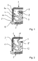
- FIG. 1 is a cross section of a seal assembly to see.
- This comprises an outer ring 1 and an inner ring 2, each having an L-shaped cross-section.
- the outer ring 1 is connected to a stationary member, for example, an outer ring of a rolling bearing, while the inner ring 2 is fixed to a rotatable member, for example, an inner ring of a rolling bearing, in communication.
- the inner ring 2 and the outer ring 1 together define an intermediate inner space 3 in which a main gasket 4 is placed.
- This main seal 4 is connected via a static seal portion 5 fixed to the inner ring 2 and has two sealing lips 6a and 6b, which extend in the direction of the outer ring 1 and oriented radially outwardly and at a radial portion 7 of the outer ring. 1 come to the plant.
- the sealing lips 6a and 6b have such rigidity that they press at standstill of the system and low speeds of the inner ring 2 to the radial portion 7, but at higher speeds of the inner ring 2 stand out from this and accordingly no longer from this point contribute to friction losses of the seal assembly.
- a special feature of the sealing arrangement is that a radial portion 8 of the inner ring 2 is provided with recesses 9, which are arranged along the circumference of the radial portion 8 equidistant from each other on a closed circular path.
- these recesses 9 act as an encoder - not shown here - an inductive speed sensor, so that a speed of the inner ring 2 can be determined in a manner known in the art.
- the static seal member 5 of the main seal in this case surrounds the radial portion 8 of the inner ring 2 completely and also fills the recesses 9 completely.
- the static sealing part 5 furthermore has an axial extension, at the end of which a circumferential groove 10 is formed.
- This groove 10 protrudes radially in the direction of the outer ring 1 and prevents an axial sliding apart of the two rings 1 and 2 during handling or in the assembled state from a contact with the outer ring 1 further sliding.
- FIG. 2 a second sealing arrangement can be seen in cross section.
- the main seal 4 'in this case has an additional radial sealing lip 11, which extends from the radial portion 8' of the inner ring 2 in the direction of the outer ring 1 and is directed axially outward.
- this radial sealing lip 11 is in contact with the outer ring 1, so that dirt particles which have entered the gap formed between the outer ring 1 and the radial section 8 'of the inner ring 2 act on a further penetration into the interior 3 be prevented.
- the radial portion 8 'of the inner ring 2 takes along its circumference similar, permanent magnetic north and south polar areas 12, which are arranged alternately and of which in this view only a permanent magnetic north polar area N can be seen.
- These polares 12 form the encoder of a - not shown - magnetoresistive sensor, via which the speed of the inner ring 2 can be determined in a manner known to those skilled in the art.
- the static sealing part 5 of the main seal 4 ' which completely envelopes the radial section 8', the polar spots 12 are furthermore effectively protected from environmental influences. Consequently, on the one hand, a reliable Sealing the seal assembly and on the other hand, the operation of the speed detection of the inner ring 2 guaranteed.
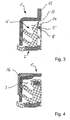
- FIG. 3 an embodiment of the seal assembly according to the invention shown in cross section.
- the static sealing part 5 'of the main seal 4 "in this case has a raised in the direction of the outer ring 1' elevation 13, which is directed axially outward and has an edge 14.
- the outer ring 1 Upon rotation of the inner ring In particular, liquids impinging on the radial portion 8 'are deflected radially outwardly due to the centrifugal forces generated by the rotation, whereby the edge 14 creates a stall in this area, which causes the centrifugal liquids to escape into the space between them.
- the outer ring 1 ' has an extension 15 pointing radially outwards, which forms an axial stop during the assembly of the sealing arrangement according to the invention.
- FIG. 4 Furthermore, a third sealing arrangement emerges.
- the outer ring 1 in contrast to the other variants, the outer ring 1 "has an angled course in the axial direction and is partially provided with a static seal 16 on the surfaces facing away from the interior 3. With the aid of this static seal 16, an entry of Contamination effectively prevented by a formed between the outer ring 1 "and the respective adjoining element gap.
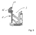
- FIG. 5 to see a fourth seal arrangement in cross section.
- the outer ring 1 "' is designed like a disk and placed away from the interior 3.
- the static seal 16' forms a circumferential one in the region of the outer diameter of the outer ring 1"' Mounting lip 17, over which the outer ring 1 "'during assembly in a corresponding groove of the respective surrounding element can be clipped in.
- a limitation of the inner space 3 in the outer radial direction is achieved by this, surrounding element.
- an entry of contaminants into the space to be sealed can be effectively prevented by the sealing arrangement according to the invention.
- the space-saving and reliable integration of an encoder for an active sensor makes the arrangement also particularly suitable for wheel bearings of motor vehicles.
- the features of the previously described embodiments of the invention are not limited to the individual embodiments, but can be combined with each other.
- a circumferentially homogeneously corrugated embodiment of the radial portion into consideration, to form an encoder for an active sensor by the thus formed in the axial direction contour.
Claims (10)
- Ensemble d'étanchéité, en particulier pour un palier de roue d'un véhicule automobile, comportant une bague extérieure fixe (1 ; 1' ; 1" ; 1"') et une bague intérieure rotative (2), lesquelles reçoivent, dans un espace intérieur (3) formé entre elles, un joint d'étanchéité principal (4 ; 4' ; 4") comprenant au moins une lèvre d'étanchéité (6a, 6b) qui s'étend entre des portions radiales (7, 8 ; 7, 8') de la bague intérieure (2) et de la bague extérieure (1 ; 1' ; 1" ; 1"') de manière orientée dans la direction axiale et radialement vers l'extérieur, le joint d'étanchéité principal (4 ; 4' ; 4") étant relié à la bague intérieure (2) par le biais d'une partie d'étanchéité statique (5 ; 5'), laquelle entoure complètement la portion radiale (8 ; 8') de la bague intérieure (2), et la portion radiale (8 ; 8') de la bague intérieure (2) formant des moyens d'un codeur pour un capteur de vitesse de rotation, et des moyens de retenue élastiques étant prévus, lesquels empêchent la bague intérieure (2) de glisser axialement par rapport à la bague extérieure (1 ; 1' ; 1" ; 1"') dans une direction,
caractérisé en ce que la partie d'étanchéité statique (5') comprend, à l'extrémité de la portion radiale (8') de la bague intérieure (2), un rehaussement (13) estampé dans la direction de la bague extérieure (1') et opposé à l'espace intérieur (3), lequel rehaussement comprend une arête (14). - Ensemble d'étanchéité selon la revendication 1,
caractérisé en ce que les moyens du codeur sont présents sous la forme de plusieurs évidements (9), lesquels sont répartis de manière équidistante les uns par rapport aux autres sur un trajet circulaire fermé de la périphérie de la portion radiale (8). - Ensemble d'étanchéité selon la revendication 1,
caractérisé en ce que les moyens du codeur sont présents sous la forme d'un agencement de régions identiques de pôle Nord et Sud à aimantation permanente (12), lesquelles sont agencées en alternance sur un trajet circulaire fermé de la périphérie de la portion radiale (8'). - Ensemble d'étanchéité selon l'une quelconque des revendications 1 à 3,
caractérisé en ce que les moyens de retenue sont formés au moyen d'un prolongement axial de la partie d'étanchéité statique (5 ; 5') par une rainure périphérique (10) faisant saillie radialement en direction de la bague extérieure (1 ; 1' ; 1" ; 1"'). - Ensemble d'étanchéité selon l'une quelconque des revendications précédentes,
caractérisé en ce que le joint d'étanchéité principal (4') présente une lèvre d'étanchéité radiale (11) qui s'étend à partir de la portion radiale (8') de la bague intérieure (2) en direction de la bague extérieure (1) et à l'opposé de l'espace intérieur (3). - Ensemble d'étanchéité selon la revendication 5,
caractérisé en ce que la lèvre d'étanchéité radiale (11) est en contact avec la bague extérieure (1) ou avec un élément environnant. - Ensemble d'étanchéité selon l'une quelconque des revendications précédentes,
caractérisé en ce que la bague extérieure (1" ; 1"') est pourvue entièrement ou partiellement d'un joint d'étanchéité statique (16 ; 16'), en particulier sur ses surfaces opposées à l'espace intérieur (3). - Ensemble d'étanchéité selon la revendication 7,
caractérisé en ce que le joint d'étanchéité statique (16') forme une lèvre de montage périphérique (17) dans la région d'un diamètre extérieur de la bague extérieure (1" '). - Ensemble d'étanchéité selon l'une quelconque des revendications précédentes,
caractérisé en ce que la bague extérieure (1') présente une étendue (15) orientée radialement vers l'extérieur. - Palier de roue d'un véhicule automobile, comportant au moins un ensemble d'étanchéité selon l'une quelconque des revendications 1 à 9, lequel forme un codeur d'un capteur de vitesse de rotation associé respectif.
Applications Claiming Priority (1)
| Application Number | Priority Date | Filing Date | Title |
|---|---|---|---|
| DE200910035110 DE102009035110A1 (de) | 2009-07-29 | 2009-07-29 | Dichtungsanordnung für eine Radlagerung eines Kraftfahrzeuges |
Publications (3)
| Publication Number | Publication Date |
|---|---|
| EP2280202A2 EP2280202A2 (fr) | 2011-02-02 |
| EP2280202A3 EP2280202A3 (fr) | 2013-11-27 |
| EP2280202B1 true EP2280202B1 (fr) | 2015-03-18 |
Family
ID=42931810
Family Applications (1)
| Application Number | Title | Priority Date | Filing Date |
|---|---|---|---|
| EP20100170998 Not-in-force EP2280202B1 (fr) | 2009-07-29 | 2010-07-28 | Dispositif d'étanchéité pour un palier de roue d'un véhicule automobile |
Country Status (2)
| Country | Link |
|---|---|
| EP (1) | EP2280202B1 (fr) |
| DE (1) | DE102009035110A1 (fr) |
Families Citing this family (6)
| Publication number | Priority date | Publication date | Assignee | Title |
|---|---|---|---|---|
| DE102011088865A1 (de) * | 2011-12-16 | 2013-06-20 | Schaeffler Technologies AG & Co. KG | Signalgeberring mit Schräge |
| DE102013210315A1 (de) * | 2013-06-04 | 2014-12-04 | Schaeffler Technologies Gmbh & Co. Kg | Wälzlager mit Encoderring und Verfahren zu dessen Montage |
| DE102014220584A1 (de) * | 2014-10-10 | 2016-04-14 | Schaeffler Technologies AG & Co. KG | Dichtungsanordnung, abgedichtete Maschinenelementanordnung sowie Wälzlager mit abgedichtetem Wälzkörperraum |
| DE102015002965B3 (de) * | 2015-03-07 | 2016-03-31 | Audi Ag | Radlageranordnung für ein Kraftfahrzeug |
| DE102016125093A1 (de) * | 2016-12-21 | 2018-06-21 | Schaeffler Technologies AG & Co. KG | Dichtsystem ohne Druckaustausch |
| DE102021105500A1 (de) | 2021-03-08 | 2022-09-08 | Carl Freudenberg Kg | Dichtring |
Family Cites Families (6)
| Publication number | Priority date | Publication date | Assignee | Title |
|---|---|---|---|---|
| FR2574501B1 (fr) * | 1984-12-11 | 1989-11-10 | Roulements Soc Nouvelle | Roulement a capteur d'informations |
| IT1206866B (it) * | 1987-01-28 | 1989-05-11 | Riv Officine Di Villar Perosa | Cuscinetto stagno per condizioni dilavoro eccezionalmente gravose |
| DE4231332C2 (de) * | 1991-09-19 | 2002-10-10 | Nsk Ltd | Lager mit passivem Impulsgeber-Ring |
| IT1288742B1 (it) * | 1996-10-08 | 1998-09-24 | Skf Ind Spa | Complesso di tenuta per un cuscinetto di rotolamento. |
| DE19853187A1 (de) | 1998-11-18 | 2000-06-15 | Fag Automobiltechnik Ag | Kassettendichtung für Wälzlager |
| ITTO20020501A1 (it) * | 2002-06-13 | 2003-12-15 | Skf Ind Spa | Dispositivo con ruota fonica integrata |
-
2009
- 2009-07-29 DE DE200910035110 patent/DE102009035110A1/de not_active Ceased
-
2010
- 2010-07-28 EP EP20100170998 patent/EP2280202B1/fr not_active Not-in-force
Also Published As
| Publication number | Publication date |
|---|---|
| DE102009035110A1 (de) | 2011-02-03 |
| EP2280202A3 (fr) | 2013-11-27 |
| EP2280202A2 (fr) | 2011-02-02 |
Similar Documents
| Publication | Publication Date | Title |
|---|---|---|
| EP2280202B1 (fr) | Dispositif d'étanchéité pour un palier de roue d'un véhicule automobile | |
| DE102010064672B3 (de) | Dichtungsanordnung zur Abdichtung eines Radlagers | |
| EP1963697B1 (fr) | Palier radial dote d'un joint d'étanchéité a cassette et joint d'étanchéité à cassette | |
| DE102012204620B4 (de) | Kassettendichtung, insbesondere für eine Radlageranordnung eines Kraftfahrzeuges, und eine Radlageranordnung mit einer solchen Kassettendichtung | |
| DE112006001263T5 (de) | Dichtungsvorrichtung mit Polrad | |
| EP2430325B1 (fr) | Dispositif d'étanchéité pour palier à roulement | |
| DE112006001262T5 (de) | Dichtungsvorrichtung | |
| WO2013120541A1 (fr) | Système de roulement de roue pourvu d'une protection de codeur et d'un dispositif de centrage | |
| EP2553474B1 (fr) | Dispositif de palier de roue comportant une butée de capteur | |
| DE102013219118B4 (de) | Flanschlager-Gehäuseeinheit | |
| DE102007049442A1 (de) | Rolle, insbesondere Standrolle für eine Postverteileranlage | |
| DE102014205055A1 (de) | Radlageranordnung für ein Kraftfahrzeug mit einem speziellen Radlagerdeckel | |
| DE102012219483B4 (de) | Schienenfahrzeug-Fahrmotor-Lageranordnung | |
| DE102007001963B4 (de) | Wälzlager mit einer Vorrichtung zur Ableitung einer Flüssigkeit | |
| DE102009019396B4 (de) | Dichtungsanordnung für eine Wälzlagerung | |
| EP3538781B1 (fr) | Ensemble de palier de roue pour véhicule à moteur | |
| EP3810943A1 (fr) | Palier à roulement et système d'étanchéité comprenant au moins deux lèvres d'étanchéité | |
| EP3330557B1 (fr) | Système de roulement de roue pour un véhicule automobile | |
| EP1736676B1 (fr) | Palier à roulement avec un élément d'étanchéité | |
| DE102015218625A1 (de) | Dichtung für eine Radlageranordnung | |
| DE102009025130A1 (de) | Dichtelement für ein Drehlager | |
| WO2010046173A1 (fr) | Palier à roulement doté d'éléments d'étanchéité | |
| WO2016124179A1 (fr) | Unite de palier de roue | |
| WO2015172774A1 (fr) | Dispositif d'étanchéité | |
| DE102017123170A1 (de) | Dichtring mit einer Rotationsachse für eine Radialwellendichtanordnung und Radialwellendichtanordnung |
Legal Events
| Date | Code | Title | Description |
|---|---|---|---|
| PUAI | Public reference made under article 153(3) epc to a published international application that has entered the european phase |
Free format text: ORIGINAL CODE: 0009012 |
|
| 17P | Request for examination filed |
Effective date: 20100728 |
|
| AK | Designated contracting states |
Kind code of ref document: A2 Designated state(s): AL AT BE BG CH CY CZ DE DK EE ES FI FR GB GR HR HU IE IS IT LI LT LU LV MC MK MT NL NO PL PT RO SE SI SK SM TR |
|
| AX | Request for extension of the european patent |
Extension state: BA ME RS |
|
| RAP1 | Party data changed (applicant data changed or rights of an application transferred) |
Owner name: SCHAEFFLER TECHNOLOGIES AG & CO. KG |
|
| PUAL | Search report despatched |
Free format text: ORIGINAL CODE: 0009013 |
|
| AK | Designated contracting states |
Kind code of ref document: A3 Designated state(s): AL AT BE BG CH CY CZ DE DK EE ES FI FR GB GR HR HU IE IS IT LI LT LU LV MC MK MT NL NO PL PT RO SE SI SK SM TR |
|
| AX | Request for extension of the european patent |
Extension state: BA ME RS |
|
| RIC1 | Information provided on ipc code assigned before grant |
Ipc: F16C 41/00 20060101ALI20131024BHEP Ipc: F16C 21/00 20060101ALI20131024BHEP Ipc: F16J 15/32 20060101AFI20131024BHEP Ipc: F16C 33/78 20060101ALI20131024BHEP |
|
| 17Q | First examination report despatched |
Effective date: 20131113 |
|
| RAP1 | Party data changed (applicant data changed or rights of an application transferred) |
Owner name: SCHAEFFLER TECHNOLOGIES GMBH & CO. KG |
|
| RBV | Designated contracting states (corrected) |
Designated state(s): AL AT BE BG CH CY CZ DE DK EE ES FI FR GB GR HR HU IE IS IT LI LT LU LV MC MK MT NL NO PL PT RO SE SI SK SM TR |
|
| GRAP | Despatch of communication of intention to grant a patent |
Free format text: ORIGINAL CODE: EPIDOSNIGR1 |
|
| RIC1 | Information provided on ipc code assigned before grant |
Ipc: F16C 21/00 20060101ALI20141008BHEP Ipc: F16C 41/00 20060101ALI20141008BHEP Ipc: F16C 33/78 20060101ALI20141008BHEP Ipc: F16J 15/32 20060101AFI20141008BHEP |
|
| INTG | Intention to grant announced |
Effective date: 20141024 |
|
| GRAS | Grant fee paid |
Free format text: ORIGINAL CODE: EPIDOSNIGR3 |
|
| GRAA | (expected) grant |
Free format text: ORIGINAL CODE: 0009210 |
|
| RAP1 | Party data changed (applicant data changed or rights of an application transferred) |
Owner name: SCHAEFFLER TECHNOLOGIES AG & CO. KG |
|
| AK | Designated contracting states |
Kind code of ref document: B1 Designated state(s): AL AT BE BG CH CY CZ DE DK EE ES FI FR GB GR HR HU IE IS IT LI LT LU LV MC MK MT NL NO PL PT RO SE SI SK SM TR |
|
| REG | Reference to a national code |
Ref country code: GB Ref legal event code: FG4D Free format text: NOT ENGLISH |
|
| REG | Reference to a national code |
Ref country code: CH Ref legal event code: EP |
|
| REG | Reference to a national code |
Ref country code: IE Ref legal event code: FG4D Free format text: LANGUAGE OF EP DOCUMENT: GERMAN |
|
| REG | Reference to a national code |
Ref country code: AT Ref legal event code: REF Ref document number: 716802 Country of ref document: AT Kind code of ref document: T Effective date: 20150415 |
|
| REG | Reference to a national code |
Ref country code: DE Ref legal event code: R096 Ref document number: 502010009143 Country of ref document: DE Effective date: 20150430 |
|
| REG | Reference to a national code |
Ref country code: NL Ref legal event code: VDEP Effective date: 20150318 |
|
| REG | Reference to a national code |
Ref country code: NL Ref legal event code: VDEP Effective date: 20150318 |
|
| PG25 | Lapsed in a contracting state [announced via postgrant information from national office to epo] |
Ref country code: HR Free format text: LAPSE BECAUSE OF FAILURE TO SUBMIT A TRANSLATION OF THE DESCRIPTION OR TO PAY THE FEE WITHIN THE PRESCRIBED TIME-LIMIT Effective date: 20150318 Ref country code: FI Free format text: LAPSE BECAUSE OF FAILURE TO SUBMIT A TRANSLATION OF THE DESCRIPTION OR TO PAY THE FEE WITHIN THE PRESCRIBED TIME-LIMIT Effective date: 20150318 Ref country code: LT Free format text: LAPSE BECAUSE OF FAILURE TO SUBMIT A TRANSLATION OF THE DESCRIPTION OR TO PAY THE FEE WITHIN THE PRESCRIBED TIME-LIMIT Effective date: 20150318 Ref country code: SE Free format text: LAPSE BECAUSE OF FAILURE TO SUBMIT A TRANSLATION OF THE DESCRIPTION OR TO PAY THE FEE WITHIN THE PRESCRIBED TIME-LIMIT Effective date: 20150318 Ref country code: NO Free format text: LAPSE BECAUSE OF FAILURE TO SUBMIT A TRANSLATION OF THE DESCRIPTION OR TO PAY THE FEE WITHIN THE PRESCRIBED TIME-LIMIT Effective date: 20150618 |
|
| REG | Reference to a national code |
Ref country code: LT Ref legal event code: MG4D |
|
| PG25 | Lapsed in a contracting state [announced via postgrant information from national office to epo] |
Ref country code: GR Free format text: LAPSE BECAUSE OF FAILURE TO SUBMIT A TRANSLATION OF THE DESCRIPTION OR TO PAY THE FEE WITHIN THE PRESCRIBED TIME-LIMIT Effective date: 20150619 Ref country code: LV Free format text: LAPSE BECAUSE OF FAILURE TO SUBMIT A TRANSLATION OF THE DESCRIPTION OR TO PAY THE FEE WITHIN THE PRESCRIBED TIME-LIMIT Effective date: 20150318 |
|
| PG25 | Lapsed in a contracting state [announced via postgrant information from national office to epo] |
Ref country code: NL Free format text: LAPSE BECAUSE OF FAILURE TO SUBMIT A TRANSLATION OF THE DESCRIPTION OR TO PAY THE FEE WITHIN THE PRESCRIBED TIME-LIMIT Effective date: 20150318 |
|
| PG25 | Lapsed in a contracting state [announced via postgrant information from national office to epo] |
Ref country code: ES Free format text: LAPSE BECAUSE OF FAILURE TO SUBMIT A TRANSLATION OF THE DESCRIPTION OR TO PAY THE FEE WITHIN THE PRESCRIBED TIME-LIMIT Effective date: 20150318 Ref country code: EE Free format text: LAPSE BECAUSE OF FAILURE TO SUBMIT A TRANSLATION OF THE DESCRIPTION OR TO PAY THE FEE WITHIN THE PRESCRIBED TIME-LIMIT Effective date: 20150318 Ref country code: RO Free format text: LAPSE BECAUSE OF FAILURE TO SUBMIT A TRANSLATION OF THE DESCRIPTION OR TO PAY THE FEE WITHIN THE PRESCRIBED TIME-LIMIT Effective date: 20150318 Ref country code: SK Free format text: LAPSE BECAUSE OF FAILURE TO SUBMIT A TRANSLATION OF THE DESCRIPTION OR TO PAY THE FEE WITHIN THE PRESCRIBED TIME-LIMIT Effective date: 20150318 Ref country code: CZ Free format text: LAPSE BECAUSE OF FAILURE TO SUBMIT A TRANSLATION OF THE DESCRIPTION OR TO PAY THE FEE WITHIN THE PRESCRIBED TIME-LIMIT Effective date: 20150318 Ref country code: PT Free format text: LAPSE BECAUSE OF FAILURE TO SUBMIT A TRANSLATION OF THE DESCRIPTION OR TO PAY THE FEE WITHIN THE PRESCRIBED TIME-LIMIT Effective date: 20150720 |
|
| PG25 | Lapsed in a contracting state [announced via postgrant information from national office to epo] |
Ref country code: PL Free format text: LAPSE BECAUSE OF FAILURE TO SUBMIT A TRANSLATION OF THE DESCRIPTION OR TO PAY THE FEE WITHIN THE PRESCRIBED TIME-LIMIT Effective date: 20150318 Ref country code: IS Free format text: LAPSE BECAUSE OF FAILURE TO SUBMIT A TRANSLATION OF THE DESCRIPTION OR TO PAY THE FEE WITHIN THE PRESCRIBED TIME-LIMIT Effective date: 20150718 |
|
| REG | Reference to a national code |
Ref country code: DE Ref legal event code: R097 Ref document number: 502010009143 Country of ref document: DE |
|
| PG25 | Lapsed in a contracting state [announced via postgrant information from national office to epo] |
Ref country code: IT Free format text: LAPSE BECAUSE OF FAILURE TO SUBMIT A TRANSLATION OF THE DESCRIPTION OR TO PAY THE FEE WITHIN THE PRESCRIBED TIME-LIMIT Effective date: 20150318 |
|
| PLBE | No opposition filed within time limit |
Free format text: ORIGINAL CODE: 0009261 |
|
| STAA | Information on the status of an ep patent application or granted ep patent |
Free format text: STATUS: NO OPPOSITION FILED WITHIN TIME LIMIT |
|
| PG25 | Lapsed in a contracting state [announced via postgrant information from national office to epo] |
Ref country code: DK Free format text: LAPSE BECAUSE OF FAILURE TO SUBMIT A TRANSLATION OF THE DESCRIPTION OR TO PAY THE FEE WITHIN THE PRESCRIBED TIME-LIMIT Effective date: 20150318 |
|
| 26N | No opposition filed |
Effective date: 20151221 |
|
| PG25 | Lapsed in a contracting state [announced via postgrant information from national office to epo] |
Ref country code: MC Free format text: LAPSE BECAUSE OF FAILURE TO SUBMIT A TRANSLATION OF THE DESCRIPTION OR TO PAY THE FEE WITHIN THE PRESCRIBED TIME-LIMIT Effective date: 20150318 Ref country code: SI Free format text: LAPSE BECAUSE OF FAILURE TO SUBMIT A TRANSLATION OF THE DESCRIPTION OR TO PAY THE FEE WITHIN THE PRESCRIBED TIME-LIMIT Effective date: 20150318 |
|
| REG | Reference to a national code |
Ref country code: CH Ref legal event code: PL |
|
| GBPC | Gb: european patent ceased through non-payment of renewal fee |
Effective date: 20150728 |
|
| PG25 | Lapsed in a contracting state [announced via postgrant information from national office to epo] |
Ref country code: LU Free format text: LAPSE BECAUSE OF FAILURE TO SUBMIT A TRANSLATION OF THE DESCRIPTION OR TO PAY THE FEE WITHIN THE PRESCRIBED TIME-LIMIT Effective date: 20150728 |
|
| REG | Reference to a national code |
Ref country code: IE Ref legal event code: MM4A |
|
| PG25 | Lapsed in a contracting state [announced via postgrant information from national office to epo] |
Ref country code: CH Free format text: LAPSE BECAUSE OF NON-PAYMENT OF DUE FEES Effective date: 20150731 Ref country code: GB Free format text: LAPSE BECAUSE OF NON-PAYMENT OF DUE FEES Effective date: 20150728 Ref country code: LI Free format text: LAPSE BECAUSE OF NON-PAYMENT OF DUE FEES Effective date: 20150731 |
|
| REG | Reference to a national code |
Ref country code: FR Ref legal event code: ST Effective date: 20160331 |
|
| PG25 | Lapsed in a contracting state [announced via postgrant information from national office to epo] |
Ref country code: FR Free format text: LAPSE BECAUSE OF NON-PAYMENT OF DUE FEES Effective date: 20150731 |
|
| PG25 | Lapsed in a contracting state [announced via postgrant information from national office to epo] |
Ref country code: IE Free format text: LAPSE BECAUSE OF NON-PAYMENT OF DUE FEES Effective date: 20150728 |
|
| REG | Reference to a national code |
Ref country code: AT Ref legal event code: MM01 Ref document number: 716802 Country of ref document: AT Kind code of ref document: T Effective date: 20150728 |
|
| PG25 | Lapsed in a contracting state [announced via postgrant information from national office to epo] |
Ref country code: AT Free format text: LAPSE BECAUSE OF NON-PAYMENT OF DUE FEES Effective date: 20150728 |
|
| PG25 | Lapsed in a contracting state [announced via postgrant information from national office to epo] |
Ref country code: MT Free format text: LAPSE BECAUSE OF FAILURE TO SUBMIT A TRANSLATION OF THE DESCRIPTION OR TO PAY THE FEE WITHIN THE PRESCRIBED TIME-LIMIT Effective date: 20150318 |
|
| PG25 | Lapsed in a contracting state [announced via postgrant information from national office to epo] |
Ref country code: HU Free format text: LAPSE BECAUSE OF FAILURE TO SUBMIT A TRANSLATION OF THE DESCRIPTION OR TO PAY THE FEE WITHIN THE PRESCRIBED TIME-LIMIT; INVALID AB INITIO Effective date: 20100728 Ref country code: BG Free format text: LAPSE BECAUSE OF FAILURE TO SUBMIT A TRANSLATION OF THE DESCRIPTION OR TO PAY THE FEE WITHIN THE PRESCRIBED TIME-LIMIT Effective date: 20150318 Ref country code: SM Free format text: LAPSE BECAUSE OF FAILURE TO SUBMIT A TRANSLATION OF THE DESCRIPTION OR TO PAY THE FEE WITHIN THE PRESCRIBED TIME-LIMIT Effective date: 20150318 |
|
| PG25 | Lapsed in a contracting state [announced via postgrant information from national office to epo] |
Ref country code: CY Free format text: LAPSE BECAUSE OF FAILURE TO SUBMIT A TRANSLATION OF THE DESCRIPTION OR TO PAY THE FEE WITHIN THE PRESCRIBED TIME-LIMIT Effective date: 20150318 |
|
| PG25 | Lapsed in a contracting state [announced via postgrant information from national office to epo] |
Ref country code: BE Free format text: LAPSE BECAUSE OF NON-PAYMENT OF DUE FEES Effective date: 20150731 |
|
| PG25 | Lapsed in a contracting state [announced via postgrant information from national office to epo] |
Ref country code: TR Free format text: LAPSE BECAUSE OF FAILURE TO SUBMIT A TRANSLATION OF THE DESCRIPTION OR TO PAY THE FEE WITHIN THE PRESCRIBED TIME-LIMIT Effective date: 20150318 |
|
| PG25 | Lapsed in a contracting state [announced via postgrant information from national office to epo] |
Ref country code: MK Free format text: LAPSE BECAUSE OF FAILURE TO SUBMIT A TRANSLATION OF THE DESCRIPTION OR TO PAY THE FEE WITHIN THE PRESCRIBED TIME-LIMIT Effective date: 20150318 |
|
| PG25 | Lapsed in a contracting state [announced via postgrant information from national office to epo] |
Ref country code: AL Free format text: LAPSE BECAUSE OF FAILURE TO SUBMIT A TRANSLATION OF THE DESCRIPTION OR TO PAY THE FEE WITHIN THE PRESCRIBED TIME-LIMIT Effective date: 20150318 |
|
| PGFP | Annual fee paid to national office [announced via postgrant information from national office to epo] |
Ref country code: DE Payment date: 20210920 Year of fee payment: 12 |
|
| REG | Reference to a national code |
Ref country code: DE Ref legal event code: R119 Ref document number: 502010009143 Country of ref document: DE |
|
| PG25 | Lapsed in a contracting state [announced via postgrant information from national office to epo] |
Ref country code: DE Free format text: LAPSE BECAUSE OF NON-PAYMENT OF DUE FEES Effective date: 20230201 |
|
| P01 | Opt-out of the competence of the unified patent court (upc) registered |
Effective date: 20230523 |