EP1963603B1 - Treibstangengetriebe - Google Patents
Treibstangengetriebe Download PDFInfo
- Publication number
- EP1963603B1 EP1963603B1 EP06830025A EP06830025A EP1963603B1 EP 1963603 B1 EP1963603 B1 EP 1963603B1 EP 06830025 A EP06830025 A EP 06830025A EP 06830025 A EP06830025 A EP 06830025A EP 1963603 B1 EP1963603 B1 EP 1963603B1
- Authority
- EP
- European Patent Office
- Prior art keywords
- driving rod
- gear mechanism
- gearwheel
- rod gear
- mechanism according
- Prior art date
- Legal status (The legal status is an assumption and is not a legal conclusion. Google has not performed a legal analysis and makes no representation as to the accuracy of the status listed.)
- Active
Links
- 230000033001 locomotion Effects 0.000 claims abstract description 12
- 239000000945 filler Substances 0.000 claims description 7
- 239000000470 constituent Substances 0.000 abstract 1
- 230000005540 biological transmission Effects 0.000 description 13
- 238000006073 displacement reaction Methods 0.000 description 5
- 238000013459 approach Methods 0.000 description 4
- 238000009434 installation Methods 0.000 description 2
- 230000008719 thickening Effects 0.000 description 2
- GHYOCDFICYLMRF-UTIIJYGPSA-N (2S,3R)-N-[(2S)-3-(cyclopenten-1-yl)-1-[(2R)-2-methyloxiran-2-yl]-1-oxopropan-2-yl]-3-hydroxy-3-(4-methoxyphenyl)-2-[[(2S)-2-[(2-morpholin-4-ylacetyl)amino]propanoyl]amino]propanamide Chemical compound C1(=CCCC1)C[C@@H](C(=O)[C@@]1(OC1)C)NC([C@H]([C@@H](C1=CC=C(C=C1)OC)O)NC([C@H](C)NC(CN1CCOCC1)=O)=O)=O GHYOCDFICYLMRF-UTIIJYGPSA-N 0.000 description 1
- 238000005452 bending Methods 0.000 description 1
- 229940125797 compound 12 Drugs 0.000 description 1
- 230000008878 coupling Effects 0.000 description 1
- 238000010168 coupling process Methods 0.000 description 1
- 238000005859 coupling reaction Methods 0.000 description 1
- 230000002349 favourable effect Effects 0.000 description 1
- 238000004519 manufacturing process Methods 0.000 description 1
- 230000000717 retained effect Effects 0.000 description 1
- 239000007787 solid Substances 0.000 description 1
Images


Classifications
-
- E—FIXED CONSTRUCTIONS
- E05—LOCKS; KEYS; WINDOW OR DOOR FITTINGS; SAFES
- E05C—BOLTS OR FASTENING DEVICES FOR WINGS, SPECIALLY FOR DOORS OR WINDOWS
- E05C9/00—Arrangements of simultaneously actuated bolts or other securing devices at well-separated positions on the same wing
- E05C9/02—Arrangements of simultaneously actuated bolts or other securing devices at well-separated positions on the same wing with one sliding bar for fastening when moved in one direction and unfastening when moved in opposite direction; with two sliding bars moved in the same direction when fastening or unfastening
- E05C9/021—Arrangements of simultaneously actuated bolts or other securing devices at well-separated positions on the same wing with one sliding bar for fastening when moved in one direction and unfastening when moved in opposite direction; with two sliding bars moved in the same direction when fastening or unfastening with rack and pinion mechanism
-
- E—FIXED CONSTRUCTIONS
- E05—LOCKS; KEYS; WINDOW OR DOOR FITTINGS; SAFES
- E05C—BOLTS OR FASTENING DEVICES FOR WINGS, SPECIALLY FOR DOORS OR WINDOWS
- E05C9/00—Arrangements of simultaneously actuated bolts or other securing devices at well-separated positions on the same wing
- E05C9/10—Actuating mechanisms for bars
Definitions
- the invention relates to a drive rod transmission according to the preamble of claim 1.
- a drive rod transmission in which a pivot lever can be pivoted via a control lever.
- the pivot lever has a slot in which a driver is slidably mounted. Within the slot, the driver can be specified. The driver engages in a slot of a slide, so that upon rotation of the pivot lever, the slider is displaced over the driver. A displacement of the driver in the slot of the pivot lever causes a change in the achievable stroke of the espagnolette.
- espagnolette gearboxes have become known, which, similar to the first-mentioned prior art, try to achieve a maximum stroke with the smallest possible dimensions of the espagnolette gearbox.
- the gear used has a range of motion of 90 °.
- Such a drive rod transmission is therefore not suitable for use in a tilt-turn window, which has three functional positions, since the achievable stroke is not sufficient to adjust the various switching positions.
- the known solutions employ a gear with a 90 ° toothed area.
- the pitch circle is dimensioned such that a 180 ° switching path could not be accommodated in the existing room conditions and corresponds to the conventional drive rod drives with a 90 ° operation. This allows the existing bolt engagements to continue to be used.
- the invention is therefore based on the object to develop an espagnolette transmission according to the preamble of claim 1 so that it achieves a maximum stroke in a range of movement of the operating lever of 180 ° with the smallest dimensions.
- the arrangement ensures that, for example, a 180 ° movement of the pivot lever leads to a rotational movement of the gear of more than 180 °.
- the drive rod can be moved according to the enlarged angle range.
- a espagnolette which is received in an open fitting receiving groove on the rebate surface of the wing, provided that the pivot axes lie on a plane perpendicular to the folding surface line.
- the pivot axis of the pivot lever is in the direction of the folding surface in front of the pivot axis of the gear.
- the axis of the operating lever is therefore in front of the folding surface and the pivot lever can dip in a movement in the Betschfactnut.
- the gear is in driving connection with at least one intermediate gear, which cooperates with the drive rod.
- pivot lever has a slot in which engages an eccentrically mounted on the gear driver. This eliminates the gear otherwise mounted recesses; which can serve as backdrops. These recesses on the gear would also increase the necessary dimensions of the gear, as they must not affect the pitch circle.
- the pivot lever can be accommodated in the usual space of the housing of the espagnolette gear and the usual operation of the espagnolette for a tilt-turn leaves is maintained.
- the gear and the at least one intermediate gear have a one-sided and over the flat surfaces projecting bearing lug, which is associated with bearing openings in the housing.
- the housing can be simplified.
- the bearing of the pivot lever in the housing is realized in that the pivot lever has a coaxial with the pivot axis extending trunnion, in which a polygonal receptacle is mounted for engagement of a polygonal mandrel of the operating lever.
- the bearing pin is used at the same time as a thickening for the engagement of the polygonal mandrel.
- the housing is designed as a trough having bearing bores in a side wall for the bearing projections of the gear and the at least one intermediate gear, wherein the distance of the side walls is dimensioned larger than the dimension of the gear or the intermediate gear along the pivot axis and the gear or the at least one intermediate gear is held via a filler in the bearing bores.
- the filler For mounting or fixing the gear and the at least one intermediate wheel, it is only necessary to insert the filler into the housing.
- a particularly simple embodiment also provides that the driver is designed as a cylindrical bolt which is fixed in a bore of the gear.
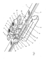
- FIG. 1 the drive rod gear 1 is shown in the assembled state.
- a housing 2 of the drive rod transmission 1 projects beyond a face-plate 3. From the housing 2 further protrudes a projection 4, which has a polygonal receptacle 5 for coupling with a shaft of an operating lever, which is not shown here.
- threaded holes 6 are provided on the housing in which fixing screws of the operating lever find an abutment.
- the housing 2 is fastened by fastening lugs 7 on the faceplate 3, which protrude from a U-shaped bottom 8 and penetrate the faceplate 3 at openings provided for this purpose.
- the espagnolette gear 1 in addition to the faceplate 3 on a rail-shaped drive rod 9, which is guided longitudinally displaceably below the faceplate 3.
- a device is provided which converts the rotational movement of the operating lever into a translational movement of the drive rod.
- the device consists of a pivot lever 10 and a link-driver connection 11.
- the slide-driving connection 11 consists of a mounted on the gear 12 driver 13 and a mounted in the pivot lever 10 scenery in the form of a slot 14.
- the gear 12 is connected to two intermediate wheels 15, 16 in drive connection, as explained in more detail below will be.
- the mounting of the pivot lever 10 in the housing 2 is realized in that the pivot lever 10 has a coaxial with its pivot axis 17 extending thickened pivot pin 18, in which the polygonal receptacle 5 is mounted for engagement of a polygonal mandrel of the operating lever.
- the bearing pin 18 is simultaneously used as a thickening for the engagement of the polygonal mandrel.
- For receiving the bearing pin 18 in the housing 2 is an edge-open recess 19th
- the drive rod 9 has a downward bend 21 in the direction of the bottom 8. In the region of the bend 21, the drive rod 9 is provided with recesses 22, which cooperate as a drive toothing with the teeth 23 of the intermediate wheels 15,16.
- the installation state of the espagnolette gear 1 results in a window 25 with a first wing 26 and a second wing 27, which are formed from hollow chamber profiles 28 and 29.
- An inner blow bar 30 is attached to the end face 31 of the wing 26 and covers in the closed state, the end face 32 of the wing 27, so that the gap 33 is hidden.
- a control lever 34 is mounted, which penetrates 35 holes of the blow bar 30 and the wing 26 with a polygonal mandrel.
- the operating lever 34 is rotatably supported by a rosette 36 and the polygonal mandrel 35 is rotatably received in a polygonal receptacle 37 of the operating lever 34.
- the pivot axis 17 of the polygonal mandrel 35 and the coupled therewith the pivot lever 10 is in the embodiment in front of the folding surface 38, in which the Betschaidnut 39 is mounted. It is according to the invention, however, also possible to make a different arrangement in which the pivot axis 17 - in the drawing - below the rebate surface 38. Die Stulpschiene 3 desmaschinestangengetriebes 1 ist mit dem Falz Chemistry 38 butter.
- FIGS. 4a to 4c and 5a to 5c the operation of the drive rod transmission 1 is shown.
- the FIGS. 4a to 4c show the invention in a view from behind and the FIGS. 4a to 4c show the front view in a two-dimensional representation.
- the driver 13 is mounted eccentrically on a gear 12 which - as already described in more detail above - is rotatably mounted on the bearing pin 18 in the housing 2 of the espagnolette gear 1, not shown here.
- FIGS. 5a to 5c can be seen that the pivot axis 17 of the pivot lever 10 and the pivot axis 40 of the gear 12 are offset from each other.
- the gear 12 performs an angular range 41 of almost 270 °.
- the drive rod 9 can be according to a relation to that of the pivot lever 10 and the Control lever 34 enlarged angle range 41 move further.
- the gear 12 with at least one intermediate gear - in the exemplary embodiment, two intermediate wheels 15, 16 - is in drive connection, which cooperate with the drive rod 9.
- the switching sequence of the espagnolette gear 2 changes.
- the achievable stroke is extended, in which the pitch of the intermediate wheels 15, 16 smaller than the pitch circle of the gear 12 is designed. As a result, a further gear ratio is achieved, so that at a necessary total stroke of the drive rod 9, the dimensions of the gear 12 can be reduced.
- FIGS. 5a to c are the pivot axes 17, 40 on a perpendicular to the folding surface 38 - which is here represented by the faceplate 3 - extending line 42.
- the approach 4 of the pivot lever 10 is completely in front of the faceplate 3, which requires no bending or the like. In a drive rod transmission 1, which is received in the open Betschagenut 39, this results in the advantage that the approach 4 can be made comparatively solid, since this does not have to be included in the Beschlagagenut 39.
- the faceplate 3 is shown in the Fig. 4a to c provided with a window-like opening 44.
- the intermediate wheels 15, 16 and the gear 12 are - held by the housing 2, not shown here - in the opening 44, wherein the axes of the intermediate wheels 15, 16 in the region of the opening 44 and the pivot axis 40 of the gear 12 are in front of the faceplate 3 or lies.
- the pivot axis 17 of the pivot lever 10 is in the direction of the folding surface 38 in front of the pivot axis 40 of the gear 12, the pivot arm 45 can dip during pivoting of the pivot lever 10 in the opening 44.
- This is used in the exemplary embodiment to maximize the usable length of the pivot arm, which can be designed so that this in the position after Fig. 4b and 5b does not abut the drive rod 9.
- the maximum stroke of the espagnolette gear 1 is extended.
- the pivot arm 45 of the pivot lever 10 has a slot 46 into which the eccentrically mounted on the gear 12 driver 13 engages.
- the Schwenkarmand and the slot 46 are dimensioned so that the pivot lever 10 can pass through the desired pivot angle of 180 °.
- the driver 13 is formed in the illustrated embodiment as a cylindrical bolt which is fixed in a bore of the gear 12. It can alternatively be provided, of course, that the driver 13 is formed integrally with the gear 12.
- the driver 13 passes through in the Fig. 5a shown position, due to the eccentric position of the pivot lever 10 relative to the gear 12, during pivoting of the pivot arm 10, the slot 46 until it is in the 90 ° position ( Fig. 4b ) has reached the outer end of the slot 46. If the swivel arm 10 is now in the in Fig. 5c shown position further moves, so the driver 13 passes through the slot 46 in the opposite direction and finally approaches the starting position again Fig. 5a , This results in a favorable force distribution for the pivot lever 10. In the position after Fig. 5a the locking elements of the wing 26 are engaged with the locking engagement associated therewith.
- the pivot arm 45 of the pivot lever 10 can therefore be kept relatively narrow, which affects the depth, ie in a direction transverse to the direction of displacement of the drive rod 9 low.
- the gear 12 has a one-sided cylindrical bearing lug 47 projecting from the flat surface 48, which faces away from the pivot lever 10 and the driver 13.
- This bearing lug 47 is associated with a bearing opening in the housing 2.
- the housing 2 of the drive rod transmission 1 is for this purpose designed as a trough, which has bearing bores for engaging the bearing projection 47 on the inside in a side wall.
- the intermediate wheels 15, 16 have a only on one side on a flat surface 48, 49 projecting bearing lug 50, 51. This can be assigned as well as the bearing lug 47 of a bearing bore in the housing 2.
- the distance of the side walls is dimensioned larger than the dimension of the gear 12 and the intermediate wheels along the pivot axes 40, 52, 53.
- the intermediate wheels 15,16 can characterized in introduced the trough-shaped housing 2 and mounted by lateral displacement in the bearing bores on the housing 2.
- the intermediate wheels 15,16 and the gear 12 occupy a position in the functional position, in which the flat surfaces 48, 49 and the flat surface 54 (FIG. Fig. 4c ) as well as the opposite plano surfaces are approximately aligned.
- the pivot lever 10 can thereby engage with the pivot arm 45 and the intermediate wheels 15, 16 ( Figures 5a and 5c) and the fixing of the position of the components can via a filler 55 ( Fig.
- the filler 2 is adapted to the dimensions of the intermediate wheels 15,16 and the gear 12 and the dimensions of the housing 2 so that they can not be removed from the bearing bores with a mounted filler 55.
- the intermediate wheels 15,16 and the gear 12 with the pivot lever 10 are inserted into the housing 2.
- the filler 55 is mounted, which may be fixed, for example, with a locking means on the housing 2.
- Such mounted drive rod drive modules can be stored in a space-saving preassembled and mounted if necessary by means of the bottom 8 of corresponding length-graded cuff rails 3 and drive rods 9.
- the design of the drive rod 1 can also be done without intermediate wheels 15, 16 and that the invention can also be used in espagnolettes, which have a pivot axis 17 which lies behind the folding surface 38.
Landscapes
- Engineering & Computer Science (AREA)
- Mechanical Engineering (AREA)
- Transmission Devices (AREA)
- Control Of Throttle Valves Provided In The Intake System Or In The Exhaust System (AREA)
- Vehicle Body Suspensions (AREA)
- Body Structure For Vehicles (AREA)
- Retarders (AREA)
- Valve Device For Special Equipments (AREA)
- Power-Operated Mechanisms For Wings (AREA)
Priority Applications (1)
| Application Number | Priority Date | Filing Date | Title |
|---|---|---|---|
| PL06830025T PL1963603T3 (pl) | 2005-12-20 | 2006-11-17 | Mechanizm z drążkiem napędowym |
Applications Claiming Priority (2)
| Application Number | Priority Date | Filing Date | Title |
|---|---|---|---|
| DE102005000191A DE102005000191A1 (de) | 2005-12-20 | 2005-12-20 | Treibstangengetriebe |
| PCT/EP2006/068605 WO2007071509A1 (de) | 2005-12-20 | 2006-11-17 | Treibstangengetriebe |
Publications (2)
| Publication Number | Publication Date |
|---|---|
| EP1963603A1 EP1963603A1 (de) | 2008-09-03 |
| EP1963603B1 true EP1963603B1 (de) | 2009-08-12 |
Family
ID=37847291
Family Applications (1)
| Application Number | Title | Priority Date | Filing Date |
|---|---|---|---|
| EP06830025A Active EP1963603B1 (de) | 2005-12-20 | 2006-11-17 | Treibstangengetriebe |
Country Status (6)
| Country | Link |
|---|---|
| EP (1) | EP1963603B1 (pl) |
| AT (1) | ATE439497T1 (pl) |
| DE (2) | DE102005000191A1 (pl) |
| DK (1) | DK1963603T3 (pl) |
| PL (1) | PL1963603T3 (pl) |
| WO (1) | WO2007071509A1 (pl) |
Cited By (1)
| Publication number | Priority date | Publication date | Assignee | Title |
|---|---|---|---|---|
| DE102021106475A1 (de) | 2021-03-17 | 2022-09-22 | Maco Technologie Gmbh | Betätigungsgetriebe für ein fenster oder eine tür mit notentriegelungsfunktion |
Families Citing this family (2)
| Publication number | Priority date | Publication date | Assignee | Title |
|---|---|---|---|---|
| DE202009002650U1 (de) | 2009-02-26 | 2010-07-22 | Siegenia-Aubi Kg | Treibstangengetriebe |
| ATE538275T1 (de) | 2009-04-11 | 2012-01-15 | Roto Frank Ag | Treibstangengetriebe |
Family Cites Families (4)
| Publication number | Priority date | Publication date | Assignee | Title |
|---|---|---|---|---|
| DE7107673U (de) * | 1971-06-24 | Hahn F Gmbh | Getriebe fur Steuergestange an Fenstern oder Türen | |
| DE50111018D1 (de) * | 2001-10-09 | 2006-10-26 | Hautau Gmbh | Z-Förmige Getriebeanordnung |
| DE20308230U1 (de) * | 2003-05-22 | 2003-07-24 | SIEGENIA-AUBI KG, 57074 Siegen | Treibstangengetriebe |
| DE10323704B4 (de) * | 2003-05-22 | 2011-07-21 | Siegenia-Aubi Kg, 57234 | Treibstangengetriebe |
-
2005
- 2005-12-20 DE DE102005000191A patent/DE102005000191A1/de not_active Withdrawn
-
2006
- 2006-11-17 WO PCT/EP2006/068605 patent/WO2007071509A1/de not_active Ceased
- 2006-11-17 PL PL06830025T patent/PL1963603T3/pl unknown
- 2006-11-17 DK DK06830025T patent/DK1963603T3/da active
- 2006-11-17 AT AT06830025T patent/ATE439497T1/de active
- 2006-11-17 DE DE502006004556T patent/DE502006004556D1/de active Active
- 2006-11-17 EP EP06830025A patent/EP1963603B1/de active Active
Cited By (1)
| Publication number | Priority date | Publication date | Assignee | Title |
|---|---|---|---|---|
| DE102021106475A1 (de) | 2021-03-17 | 2022-09-22 | Maco Technologie Gmbh | Betätigungsgetriebe für ein fenster oder eine tür mit notentriegelungsfunktion |
Also Published As
| Publication number | Publication date |
|---|---|
| EP1963603A1 (de) | 2008-09-03 |
| WO2007071509A1 (de) | 2007-06-28 |
| DE502006004556D1 (de) | 2009-09-24 |
| PL1963603T3 (pl) | 2010-01-29 |
| ATE439497T1 (de) | 2009-08-15 |
| DK1963603T3 (da) | 2009-12-14 |
| DE102005000191A1 (de) | 2007-06-21 |
Similar Documents
| Publication | Publication Date | Title |
|---|---|---|
| DE102016111564A1 (de) | Stangenschloss | |
| EP1359273B1 (de) | Verriegelungsbeschlag an einem Fenster, einer Tür oder dergleichen, mit gegenläufig verschiebbaren Treibstangen | |
| DE19531680C1 (de) | Betätigungsvorrichtung | |
| EP0534089B1 (de) | Betätigungsgetriebe für längsverschiebbare Treibstangen an Beschlägen von Fenstern und Türen od. dgl. | |
| EP2206860A2 (de) | Beschlag mit ausfahrbarem Verriegelungselement | |
| EP1963603B1 (de) | Treibstangengetriebe | |
| EP2143859B1 (de) | Verriegelungsvorrichtung | |
| EP3045624A1 (de) | Verriegelungsvorrichtung für einen schwenkbar gelagerten flügel | |
| EP1008713B1 (de) | Verriegelungsvorrichtung | |
| DE10354185B4 (de) | Kantengetriebe | |
| EP2735678B1 (de) | Beschlag für Fenster, Türen oder dergleichen | |
| WO2012126664A1 (de) | Schrank, insbesondere gasflaschenschrank | |
| EP0784142B1 (de) | Betätigungsgetriebe für Fenster und/oder Türbeschläge mit Stell- und/oder Verriegelungsgestänge od. dgl. | |
| EP1061215A2 (de) | Getriebeanordnung für einen Stangenverschluss | |
| DE69807608T2 (de) | Schliessvorrichtung, insbesondere Einsteckschloss mit einer Falle, für eine Fenstertür oder dergleichen | |
| DE10357721B4 (de) | Verschlußvorrichtung für Türen oder Fenster | |
| EP0367842B1 (de) | Handhebelgetriebe zum Aufschrauben auf den Flügelrahmen von Fenstern, Türen oder dergleichen | |
| EP0662556B1 (de) | Schlossvorrichtung für eine Tür oder ein Fenster | |
| DE202008008232U1 (de) | Treibstangenschloss | |
| EP0736657A1 (de) | Öffenbarer Fensterflügel/Türflügel | |
| EP3404179B1 (de) | Zylinderbetätigbares türschloss | |
| DE10334592A1 (de) | Anordnung als Teil eines Schließmechanismus | |
| DE19915218C2 (de) | Hydraulisches Fenstergetriebe | |
| EP1739260A1 (de) | Getriebe eines Beschlags eines Fensters, einer Tür oder dergleichen sowie Verfahren zum Betätigen des Getriebes | |
| AT413044B (de) | Haltevorrichtung für eine schubstange oder einen schubstangenschieber eines mehrriegelschlosses |
Legal Events
| Date | Code | Title | Description |
|---|---|---|---|
| PUAI | Public reference made under article 153(3) epc to a published international application that has entered the european phase |
Free format text: ORIGINAL CODE: 0009012 |
|
| 17P | Request for examination filed |
Effective date: 20071123 |
|
| AK | Designated contracting states |
Kind code of ref document: A1 Designated state(s): AT BE BG CH CY CZ DE DK EE ES FI FR GB GR HU IE IS IT LI LT LU LV MC NL PL PT RO SE SI SK TR |
|
| GRAP | Despatch of communication of intention to grant a patent |
Free format text: ORIGINAL CODE: EPIDOSNIGR1 |
|
| GRAS | Grant fee paid |
Free format text: ORIGINAL CODE: EPIDOSNIGR3 |
|
| GRAA | (expected) grant |
Free format text: ORIGINAL CODE: 0009210 |
|
| AK | Designated contracting states |
Kind code of ref document: B1 Designated state(s): AT BE BG CH CY CZ DE DK EE ES FI FR GB GR HU IE IS IT LI LT LU LV MC NL PL PT RO SE SI SK TR |
|
| REG | Reference to a national code |
Ref country code: GB Ref legal event code: FG4D Free format text: NOT ENGLISH |
|
| REG | Reference to a national code |
Ref country code: CH Ref legal event code: NV Representative=s name: ALDO ROEMPLER PATENTANWALT Ref country code: CH Ref legal event code: EP |
|
| REG | Reference to a national code |
Ref country code: IE Ref legal event code: FG4D |
|
| REF | Corresponds to: |
Ref document number: 502006004556 Country of ref document: DE Date of ref document: 20090924 Kind code of ref document: P |
|
| REG | Reference to a national code |
Ref country code: DK Ref legal event code: T3 |
|
| LTIE | Lt: invalidation of european patent or patent extension |
Effective date: 20090812 |
|
| PG25 | Lapsed in a contracting state [announced via postgrant information from national office to epo] |
Ref country code: LT Free format text: LAPSE BECAUSE OF FAILURE TO SUBMIT A TRANSLATION OF THE DESCRIPTION OR TO PAY THE FEE WITHIN THE PRESCRIBED TIME-LIMIT Effective date: 20090812 Ref country code: IS Free format text: LAPSE BECAUSE OF FAILURE TO SUBMIT A TRANSLATION OF THE DESCRIPTION OR TO PAY THE FEE WITHIN THE PRESCRIBED TIME-LIMIT Effective date: 20091212 Ref country code: ES Free format text: LAPSE BECAUSE OF FAILURE TO SUBMIT A TRANSLATION OF THE DESCRIPTION OR TO PAY THE FEE WITHIN THE PRESCRIBED TIME-LIMIT Effective date: 20091123 Ref country code: FI Free format text: LAPSE BECAUSE OF FAILURE TO SUBMIT A TRANSLATION OF THE DESCRIPTION OR TO PAY THE FEE WITHIN THE PRESCRIBED TIME-LIMIT Effective date: 20090812 Ref country code: SE Free format text: LAPSE BECAUSE OF FAILURE TO SUBMIT A TRANSLATION OF THE DESCRIPTION OR TO PAY THE FEE WITHIN THE PRESCRIBED TIME-LIMIT Effective date: 20090812 |
|
| REG | Reference to a national code |
Ref country code: PL Ref legal event code: T3 |
|
| NLV1 | Nl: lapsed or annulled due to failure to fulfill the requirements of art. 29p and 29m of the patents act | ||
| PG25 | Lapsed in a contracting state [announced via postgrant information from national office to epo] |
Ref country code: LV Free format text: LAPSE BECAUSE OF FAILURE TO SUBMIT A TRANSLATION OF THE DESCRIPTION OR TO PAY THE FEE WITHIN THE PRESCRIBED TIME-LIMIT Effective date: 20090812 Ref country code: SI Free format text: LAPSE BECAUSE OF FAILURE TO SUBMIT A TRANSLATION OF THE DESCRIPTION OR TO PAY THE FEE WITHIN THE PRESCRIBED TIME-LIMIT Effective date: 20090812 Ref country code: NL Free format text: LAPSE BECAUSE OF FAILURE TO SUBMIT A TRANSLATION OF THE DESCRIPTION OR TO PAY THE FEE WITHIN THE PRESCRIBED TIME-LIMIT Effective date: 20090812 |
|
| REG | Reference to a national code |
Ref country code: IE Ref legal event code: FD4D |
|
| PG25 | Lapsed in a contracting state [announced via postgrant information from national office to epo] |
Ref country code: PT Free format text: LAPSE BECAUSE OF FAILURE TO SUBMIT A TRANSLATION OF THE DESCRIPTION OR TO PAY THE FEE WITHIN THE PRESCRIBED TIME-LIMIT Effective date: 20091212 Ref country code: BG Free format text: LAPSE BECAUSE OF FAILURE TO SUBMIT A TRANSLATION OF THE DESCRIPTION OR TO PAY THE FEE WITHIN THE PRESCRIBED TIME-LIMIT Effective date: 20091112 |
|
| PG25 | Lapsed in a contracting state [announced via postgrant information from national office to epo] |
Ref country code: RO Free format text: LAPSE BECAUSE OF FAILURE TO SUBMIT A TRANSLATION OF THE DESCRIPTION OR TO PAY THE FEE WITHIN THE PRESCRIBED TIME-LIMIT Effective date: 20090812 Ref country code: IE Free format text: LAPSE BECAUSE OF FAILURE TO SUBMIT A TRANSLATION OF THE DESCRIPTION OR TO PAY THE FEE WITHIN THE PRESCRIBED TIME-LIMIT Effective date: 20090812 Ref country code: EE Free format text: LAPSE BECAUSE OF FAILURE TO SUBMIT A TRANSLATION OF THE DESCRIPTION OR TO PAY THE FEE WITHIN THE PRESCRIBED TIME-LIMIT Effective date: 20090812 |
|
| PG25 | Lapsed in a contracting state [announced via postgrant information from national office to epo] |
Ref country code: SK Free format text: LAPSE BECAUSE OF FAILURE TO SUBMIT A TRANSLATION OF THE DESCRIPTION OR TO PAY THE FEE WITHIN THE PRESCRIBED TIME-LIMIT Effective date: 20090812 |
|
| PLBE | No opposition filed within time limit |
Free format text: ORIGINAL CODE: 0009261 |
|
| STAA | Information on the status of an ep patent application or granted ep patent |
Free format text: STATUS: NO OPPOSITION FILED WITHIN TIME LIMIT |
|
| REG | Reference to a national code |
Ref country code: HU Ref legal event code: AG4A Ref document number: E007263 Country of ref document: HU |
|
| PG25 | Lapsed in a contracting state [announced via postgrant information from national office to epo] |
Ref country code: MC Free format text: LAPSE BECAUSE OF NON-PAYMENT OF DUE FEES Effective date: 20091130 |
|
| 26N | No opposition filed |
Effective date: 20100517 |
|
| PG25 | Lapsed in a contracting state [announced via postgrant information from national office to epo] |
Ref country code: GR Free format text: LAPSE BECAUSE OF FAILURE TO SUBMIT A TRANSLATION OF THE DESCRIPTION OR TO PAY THE FEE WITHIN THE PRESCRIBED TIME-LIMIT Effective date: 20091113 |
|
| PG25 | Lapsed in a contracting state [announced via postgrant information from national office to epo] |
Ref country code: LU Free format text: LAPSE BECAUSE OF NON-PAYMENT OF DUE FEES Effective date: 20091117 |
|
| PG25 | Lapsed in a contracting state [announced via postgrant information from national office to epo] |
Ref country code: CY Free format text: LAPSE BECAUSE OF FAILURE TO SUBMIT A TRANSLATION OF THE DESCRIPTION OR TO PAY THE FEE WITHIN THE PRESCRIBED TIME-LIMIT Effective date: 20090812 |
|
| PGFP | Annual fee paid to national office [announced via postgrant information from national office to epo] |
Ref country code: TR Payment date: 20091117 Year of fee payment: 4 |
|
| PG25 | Lapsed in a contracting state [announced via postgrant information from national office to epo] |
Ref country code: TR Free format text: LAPSE BECAUSE OF NON-PAYMENT OF DUE FEES Effective date: 20101117 |
|
| REG | Reference to a national code |
Ref country code: FR Ref legal event code: PLFP Year of fee payment: 10 |
|
| REG | Reference to a national code |
Ref country code: FR Ref legal event code: PLFP Year of fee payment: 11 |
|
| REG | Reference to a national code |
Ref country code: FR Ref legal event code: PLFP Year of fee payment: 12 |
|
| PGFP | Annual fee paid to national office [announced via postgrant information from national office to epo] |
Ref country code: CZ Payment date: 20211029 Year of fee payment: 16 Ref country code: DK Payment date: 20211126 Year of fee payment: 16 Ref country code: FR Payment date: 20211126 Year of fee payment: 16 Ref country code: GB Payment date: 20211126 Year of fee payment: 16 |
|
| PGFP | Annual fee paid to national office [announced via postgrant information from national office to epo] |
Ref country code: HU Payment date: 20211102 Year of fee payment: 16 Ref country code: BE Payment date: 20211123 Year of fee payment: 16 |
|
| PGFP | Annual fee paid to national office [announced via postgrant information from national office to epo] |
Ref country code: PL Payment date: 20211028 Year of fee payment: 16 |
|
| PGFP | Annual fee paid to national office [announced via postgrant information from national office to epo] |
Ref country code: IT Payment date: 20221130 Year of fee payment: 17 Ref country code: DE Payment date: 20221128 Year of fee payment: 17 Ref country code: AT Payment date: 20221128 Year of fee payment: 17 |
|
| PGFP | Annual fee paid to national office [announced via postgrant information from national office to epo] |
Ref country code: CH Payment date: 20221124 Year of fee payment: 17 |
|
| REG | Reference to a national code |
Ref country code: DK Ref legal event code: EBP Effective date: 20221130 |
|
| GBPC | Gb: european patent ceased through non-payment of renewal fee |
Effective date: 20221117 |
|
| REG | Reference to a national code |
Ref country code: BE Ref legal event code: MM Effective date: 20221130 |
|
| PG25 | Lapsed in a contracting state [announced via postgrant information from national office to epo] |
Ref country code: HU Free format text: LAPSE BECAUSE OF NON-PAYMENT OF DUE FEES Effective date: 20221118 Ref country code: CZ Free format text: LAPSE BECAUSE OF NON-PAYMENT OF DUE FEES Effective date: 20221117 |
|
| PG25 | Lapsed in a contracting state [announced via postgrant information from national office to epo] |
Ref country code: GB Free format text: LAPSE BECAUSE OF NON-PAYMENT OF DUE FEES Effective date: 20221117 Ref country code: DK Free format text: LAPSE BECAUSE OF NON-PAYMENT OF DUE FEES Effective date: 20221130 |
|
| PG25 | Lapsed in a contracting state [announced via postgrant information from national office to epo] |
Ref country code: FR Free format text: LAPSE BECAUSE OF NON-PAYMENT OF DUE FEES Effective date: 20221130 Ref country code: BE Free format text: LAPSE BECAUSE OF NON-PAYMENT OF DUE FEES Effective date: 20221130 |
|
| REG | Reference to a national code |
Ref country code: DE Ref legal event code: R119 Ref document number: 502006004556 Country of ref document: DE |
|
| REG | Reference to a national code |
Ref country code: CH Ref legal event code: PL |
|
| REG | Reference to a national code |
Ref country code: AT Ref legal event code: MM01 Ref document number: 439497 Country of ref document: AT Kind code of ref document: T Effective date: 20231117 |
|
| PG25 | Lapsed in a contracting state [announced via postgrant information from national office to epo] |
Ref country code: CH Free format text: LAPSE BECAUSE OF NON-PAYMENT OF DUE FEES Effective date: 20231130 |
|
| PG25 | Lapsed in a contracting state [announced via postgrant information from national office to epo] |
Ref country code: AT Free format text: LAPSE BECAUSE OF NON-PAYMENT OF DUE FEES Effective date: 20231117 |
|
| PG25 | Lapsed in a contracting state [announced via postgrant information from national office to epo] |
Ref country code: CH Free format text: LAPSE BECAUSE OF NON-PAYMENT OF DUE FEES Effective date: 20231130 Ref country code: AT Free format text: LAPSE BECAUSE OF NON-PAYMENT OF DUE FEES Effective date: 20231117 |
|
| PG25 | Lapsed in a contracting state [announced via postgrant information from national office to epo] |
Ref country code: DE Free format text: LAPSE BECAUSE OF NON-PAYMENT OF DUE FEES Effective date: 20240601 |
|
| PG25 | Lapsed in a contracting state [announced via postgrant information from national office to epo] |
Ref country code: DE Free format text: LAPSE BECAUSE OF NON-PAYMENT OF DUE FEES Effective date: 20240601 |
|
| PG25 | Lapsed in a contracting state [announced via postgrant information from national office to epo] |
Ref country code: IT Free format text: LAPSE BECAUSE OF NON-PAYMENT OF DUE FEES Effective date: 20231117 |
|
| PG25 | Lapsed in a contracting state [announced via postgrant information from national office to epo] |
Ref country code: IT Free format text: LAPSE BECAUSE OF NON-PAYMENT OF DUE FEES Effective date: 20231117 |
|
| PG25 | Lapsed in a contracting state [announced via postgrant information from national office to epo] |
Ref country code: PL Free format text: LAPSE BECAUSE OF NON-PAYMENT OF DUE FEES Effective date: 20221117 |
|
| PG25 | Lapsed in a contracting state [announced via postgrant information from national office to epo] |
Ref country code: PL Free format text: LAPSE BECAUSE OF NON-PAYMENT OF DUE FEES Effective date: 20221117 |