EP1963211B1 - Vorrichtung zum zusammenführen von gebinden, wie kleincontainern od. dgl. - Google Patents
Vorrichtung zum zusammenführen von gebinden, wie kleincontainern od. dgl. Download PDFInfo
- Publication number
- EP1963211B1 EP1963211B1 EP07856743A EP07856743A EP1963211B1 EP 1963211 B1 EP1963211 B1 EP 1963211B1 EP 07856743 A EP07856743 A EP 07856743A EP 07856743 A EP07856743 A EP 07856743A EP 1963211 B1 EP1963211 B1 EP 1963211B1
- Authority
- EP
- European Patent Office
- Prior art keywords
- support plates
- support plate
- engaging
- fixing
- abstract
- Prior art date
- Legal status (The legal status is an assumption and is not a legal conclusion. Google has not performed a legal analysis and makes no representation as to the accuracy of the status listed.)
- Active
Links
Images

Classifications
-
- B—PERFORMING OPERATIONS; TRANSPORTING
- B65—CONVEYING; PACKING; STORING; HANDLING THIN OR FILAMENTARY MATERIAL
- B65G—TRANSPORT OR STORAGE DEVICES, e.g. CONVEYORS FOR LOADING OR TIPPING, SHOP CONVEYOR SYSTEMS OR PNEUMATIC TUBE CONVEYORS
- B65G17/00—Conveyors having an endless traction element, e.g. a chain, transmitting movement to a continuous or substantially-continuous load-carrying surface or to a series of individual load-carriers; Endless-chain conveyors in which the chains form the load-carrying surface
- B65G17/005—Conveyors having an endless traction element, e.g. a chain, transmitting movement to a continuous or substantially-continuous load-carrying surface or to a series of individual load-carriers; Endless-chain conveyors in which the chains form the load-carrying surface comprising individual load carriers which are movably mounted
-
- B—PERFORMING OPERATIONS; TRANSPORTING
- B65—CONVEYING; PACKING; STORING; HANDLING THIN OR FILAMENTARY MATERIAL
- B65G—TRANSPORT OR STORAGE DEVICES, e.g. CONVEYORS FOR LOADING OR TIPPING, SHOP CONVEYOR SYSTEMS OR PNEUMATIC TUBE CONVEYORS
- B65G2201/00—Indexing codes relating to handling devices, e.g. conveyors, characterised by the type of product or load being conveyed or handled
- B65G2201/02—Articles
-
- B—PERFORMING OPERATIONS; TRANSPORTING
- B65—CONVEYING; PACKING; STORING; HANDLING THIN OR FILAMENTARY MATERIAL
- B65G—TRANSPORT OR STORAGE DEVICES, e.g. CONVEYORS FOR LOADING OR TIPPING, SHOP CONVEYOR SYSTEMS OR PNEUMATIC TUBE CONVEYORS
- B65G47/00—Article or material-handling devices associated with conveyors; Methods employing such devices
- B65G47/52—Devices for transferring articles or materials between conveyors i.e. discharging or feeding devices
- B65G47/68—Devices for transferring articles or materials between conveyors i.e. discharging or feeding devices adapted to receive articles arriving in one layer from one conveyor lane and to transfer them in individual layers to more than one conveyor lane or to one broader conveyor lane, or vice versa, e.g. combining the flows of articles conveyed by more than one conveyor
- B65G47/681—Devices for transferring articles or materials between conveyors i.e. discharging or feeding devices adapted to receive articles arriving in one layer from one conveyor lane and to transfer them in individual layers to more than one conveyor lane or to one broader conveyor lane, or vice versa, e.g. combining the flows of articles conveyed by more than one conveyor from distinct, separate conveyor lanes
Definitions
- the invention is directed to a device for merging containers of the type specified in the preamble of claim 1.
- Bundles that are conveyed on different feed tracks to merge via merging devices to other transport units Such a merging device often consists of a plurality of edge-side chain-guided transport rods, which rotate endlessly and are slidably disposed on or between which support plates.
- two feed paths are connected to a feed track always assigned a certain number of support plates of the conveyor and on the gap to on the other side a corresponding number of support plates for the transport container, the transport plates are laterally displaceable so that they at the end of Merging track, when the packages are transferred to a single-lane onward transport path, form a closed bandage, which is separated in the lower strand again to Generalplatten Schemeen.
- a particular disadvantage of the known device is that od by the lateral displacement of the transport plates lying on it and a plurality of plates touching transport, such as a small container, or a Verpakkungsaku, such as a cardboard. Like., By a certain amount, so that he can no longer be handed over at the exit of the assembly unit in the angle by the continuing track, was originally delivered, so that additional pivoting units for the containers must be provided below to bring them to the desired onward transport position.
- each web associated carrier plate must provide a total area each, which corresponds to the largest possible footprint of the products to be transported. If, for example, much smaller containers are brought together, large unused supporting surfaces are moved, so that the conveying capacity always depends on the largest possible object and thus often has to be chosen much too slowly.
- the object of the invention is to provide a solution with a twisting of the conveyed object between delivery to the merge device and subsequent delivery to the secondary transport device is avoided, at the same time a simple adaptation to different sizes to be processed container is guaranteed.
- the invention is characterized in that at least part of the support plates is provided with interchangeable engagement elements in the guide rails and that adjacent support plates are equipped with fixing means for forming larger support plate units together, thus ensuring that from a series of support plates transport units of the desired Size are assembled and one of the support plates, as a rule, the one which is provided approximately in the centroid area with an engagement member, the lateral displacement ensured by contact with the guide rails.
- a total surface unit is moved without their relative positions of the individual surface elements offset from one another; so that it can not come to a twisting of the object located on the surface.
- Another possibility is, e.g. form the engagement elements from the underside of the support plates as swinging guide arms, which may be designed so that they are approximately provided with handles for automatic pivoting in and out.
- the fixing brackets have handling approaches in order to allow manipulation by robots which automatically set, for example, the brackets of the desired number at the beginning of the merging station and remove it again at the end of the merging station.
- Each support plate may according to the invention e.g. with a label, such as a barcode. The like.
- the generally designated 1 device for merging containers 2 to further transport units 2a is essentially formed by a rod / chain conveyor in which a plurality of rods 3 are provided in parallel alignment with each other transversely to the conveying direction in the endless circulation, the outside edge over in the figures not shown chains 4 are driven. From the rods 3 is in the Fig. 1 and 2 only a part reproduced.
- Fig. 2 is shown as the container 2 of the (in Fig. 2 shown below) Zuglassbahn 7a are transported to the secondary web 8 on a closed association of together guided support plates, wherein according to the prior art, each support plate is provided with an inwardly facing guide, so that the transport path, the in Fig. 2 has shown oblique configuration. In the lower strand, this bandage can be loosened and brought to a new position, so that eg from the in Fig. 2 not shown upper feed path 7 can be taken several products and transported on.
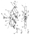
- FIG Fig. 3 a part of support plates 5 which are slidably mounted on the conveyor bars 3, wherein one of the support plates 5, especially in Fig. 3 denoted by 5a, by a centric bore 9 by means of a spur pin 10 in a located inside the device 1 U-shaped guide or track rail 6 is fixed such that the support plates can move laterally through the track rail 6. This possibility of displacement is indicated by a double arrow 12.
- the individual support plates 5 are fixed depending on the desired number of fixing means 13a, 13b or 13c to each other at least for the respective transport path.
- fixing means 13 to 13b in Fig. 3 represent only examples, here also other means may be provided, such as od in the longitudinal end faces einschwenkende od. Like.
- Fig. 4 is also indicated that, for example, instead of a spur pin 10 also einschwenkender in the guide rails 6 arm 14 may be provided, for example, an automatic pivoting and swinging possible, such as when a mechanical gripping means engages a pivot insert 15 and in the continuation of the Association in the direction of Arrows 16 pivots, which is indicated by an arrow 11, in the same way pivoting back in all those transport plates 5 is possible, which are coupled to the respective association together.
- a spur pin 10 also einschwenkender in the guide rails 6 arm 14 may be provided, for example, an automatic pivoting and swinging possible, such as when a mechanical gripping means engages a pivot insert 15 and in the continuation of the Association in the direction of Arrows 16 pivots, which is indicated by an arrow 11, in the same way pivoting back in all those transport plates 5 is possible, which are coupled to the respective association together.
- each support plate is provided with a marking, e.g. a bar code 17, which can be read by a reader 18 in a data processing program to support the further automatic control.
- a marking e.g. a bar code 17 which can be read by a reader 18 in a data processing program to support the further automatic control.
- a plurality of guide rails 6 arranged in parallel can also pivot more than one of the support plates guide elements for active side shift in the different track rails to ensure the lateral displacement trouble free, especially for heavy objects to be transported.
Landscapes
- Engineering & Computer Science (AREA)
- Mechanical Engineering (AREA)
- Supplying Of Containers To The Packaging Station (AREA)
- Specific Conveyance Elements (AREA)
- Chain Conveyers (AREA)
- Load-Engaging Elements For Cranes (AREA)
- Holders For Apparel And Elements Relating To Apparel (AREA)
- Attitude Control For Articles On Conveyors (AREA)
- Control And Other Processes For Unpacking Of Materials (AREA)
- Auxiliary Devices For And Details Of Packaging Control (AREA)
- Filling Of Jars Or Cans And Processes For Cleaning And Sealing Jars (AREA)
- Investigating Materials By The Use Of Optical Means Adapted For Particular Applications (AREA)
- Framework For Endless Conveyors (AREA)
- Basic Packing Technique (AREA)
Description
- Die Erfindung richtet sich auf eine Vorrichtung zum Zusammenführen von Gebinden der im Oberbegriff des Anspruches 1 angegebenen Gattung.
- Es ist bekannt (vgl. z.B.
US-A-3 774 748 oderEP-A-492 922 - Ein besonderer Nachteil der bekannten Vorrichtung besteht darin, dass durch das seitliche Verschieben der Transportplatten ein darauf liegendes und mehrere Platten berührendes Transportgut, wie ein Kleincontainer, oder eine Verpakkungseinheit, wie ein Karton od. dgl., um einen gewissen Betrag verdreht wird, so dass er am Ausgang der Zusammenführeinheit nicht mehr in dem Winkel durch die weiterführende Bahn übergeben werden kann, in der ursprünglich angeliefert wurde, so dass zusätzliche Verschwenkeinheiten für die Gebinde nachfolgend vorgesehen werden müssen, um sie in die gewünschte Weitertransportposition zu bringen.
- Ein weiterer Nachteil der bekannten Lösung besteht darin, dass die abschnittweise jeder Bahn zugeordneten Tragplatten eine Gesamtfläche jeweils bieten müssen, die der größtmöglichen Grundfläche der zu transportierenden Produkte entspricht. Werden beispielsweise sehr viel kleinere Gebinde zusammengeführt, werden große ungenutzte Auflageflächen bewegt, so dass sich die Förderkapazität immer nach dem größtmöglichen Objekt richtet und damit häufig viel zu langsam gewählt werden muss.
- Aufgabe der Erfindung ist die Schaffung einer Lösung, mit der zum einen ein Verdrehen des angeförderten Objektes zwischen Abgabe auf die Zusammenführvorrichtung und nachfolgende Abgabe auf die weiterführende Transportvorrichtung vermieden wird, wobei gleichzeitig eine einfache Anpassung an unterschiedlich große zu verarbeitende Gebinde gewährleistet ist.
- Bei einer Vorrichtung der eingangs bezeichneten Art wird diese Aufgabe gemäß der Erfindung durch die kennzeichnenden Merkmale des Anspruches 1 gelöst.
- Somit zeichnet sich die Erfindung dadurch aus, dass wenigstens ein Teil der Tragplatten mit auswechselbaren Eingriffselementen in die Führungsschienen versehen ist und dass benachbarte Tragplatten mit Fixiermitteln zur Bildung von größeren Tragplatteneinheiten aneinander ausgerüstet sind, womit gewährleistet ist, dass aus einer Reihe von Tragplatten Transporteinheiten der gewünschten Größe zusammenstellbar sind und eine der Tragplatten, im Regelfalle diejenige, die etwa im Flächenschwerpunktbereich mit einem Eingriffselement versehen ist, das die seitliche Verschiebung durch Kontakt mit den Führungsschienen gewährleistet. Damit wird eine Gesamtflächeneinheit bewegt, ohne dass sich deren relative Positionen der einzelnen Flächenelemente zueinander versetzt; so dass es auch nicht zu einem Verdrehen des auf der Fläche befindlichen Objektes kommen kann.
- Ausgestaltungen der Erfindung ergeben sich aus den Unteransprüchen. Dabei kann es zweckmäßig sein, auswechselbare Eingriffselemente an den Tragplatten vorzusehen, z.B. Zapfen, die direkt von der Oberseite durch die entsprechenden Tragplatten gesteckt werden und beispielsweise über einen Bajonettverschluss im entsprechenden Element der Tragplatte verrastbar sind. Eine solche Möglichkeit ist dann von Vorteil, wenn es nicht sehr häufig zu Umrüstungen der Plattengrößen kommt, so dass hier von Hand eine entsprechende Umrüstung vorgenommen werden kann.
- Eine andere Möglichkeit besteht darin, z.B. die Eingriffselemente von der Unterseite der Tragplatten als ausschwenkbare Führungsarme auszubilden, die so ausgestaltet sein können, dass sie etwa mit Handhabungsansätzen zum automatischen Ein- bzw. Ausschwenken versehen sind.
- Um einzelne Tragplatten zu größeren Einheiten zusammenzuschließen, ist auch vorgesehen, dass zur Fixierung entsprechende z.B. U-förmige Fixierklammern vorgesehen sind, die seitlich einsteckbar sind.
- Auch bei dieser Gestaltung kann vorgesehen sein, dass die Fixierklammern Handhabungsansätze aufweisen, um eine Manipulation durch Roboter zu ermöglichen, die beispielsweise automatisch die Klammern der gewünschten Anzahl am Beginn der Zusammenführstation entsprechend setzen und am Ende der Zusammenführstation wieder entfernen.
- Jede Tragplatte kann erfindungsgemäß z.B. mit einer Kennzeichnung, wie einem Barcode od. dgl., versehen sein, um über ein entsprechendes Rechenprogramm jeweils die einzelnen Tragplatten nach den angeförderten Objekten sich ausrichtenden Flächeneinheiten automatisch zusammenstellen zu können.
- Weitere Merkmale, Einzelheiten und Vorteile der Erfindung ergeben sich aufgrund der nachfolgenden Beschreibung sowie anhand der Zeichnung. Diese zeigt in
- Fig. 1
- eine Aufsicht auf eine Zusammenführstation nach der Erfindung,
- Fig. 2
- eine Aufsicht einer Zusammenführungsstation mit einer Anordnung der einzelnen Tragplatten nach dem Stand der Technik,
- Fig. 3
- eine vereinfachte Ausrisszeichnung eines Teiles eines Tragplattenverbandes in räumlicher Darstellung sowie in
- Fig. 4
- eine vereinfachte stirnseitige Ansicht eines Tragplattenverbandes, teilweise aufgeschnitten.
- Die allgemein mit 1 bezeichnete Vorrichtung zum Zusammenführen von Gebinden 2 zu Weitertransporteinheiten 2a wird im Wesentlichen von einem Stangen-/Kettenförderer gebildet, bei dem im Endlosumlauf eine Vielzahl von Stangen 3 in paralleler Ausrichtung zueinander quer zur Förderrichtung vorgesehen sind, die außenrandseitig über in den Figuren nicht näher dargestellte Ketten 4 angetrieben werden. Von den Stangen 3 ist in den
Fig. 1 und 2 nur ein Teil wiedergegeben. - Zwischen den Stangen oder auf den Stangen sind einzelne getrennte Tragplatten 5 quer verschiebbar positioniert, die ins Innere der Vorrichtung 1 weisende Führungen tragen, die über im Winkel zueinander positionierte Führungs- bzw. Spurschienen 6 von einer in
Fig. 1 links dargestellten außenrandseitigen Position in eine inFig. 1 rechts dargestellte zentrische Position verschiebbar sind, derart, dass die Gebinde 2 von einer ersten zuführenden Bahn 7 bzw. 7a so zusammengeschoben werden, dass sie auf der zentrischen Transportbahn 8 weitertransportierbar sind. - In
Fig. 2 ist dargestellt, wie die Gebinde 2 von der (inFig. 2 unten dargestellten) Zuführbahn 7a auf die weiterführende Bahn 8 auf einem geschlossen Verband aus zusammen geführten Tragplatten transportiert werden, wobei nach dem Stand der Technik jede Tragplatte mit einer nach innen weisenden Führung versehen ist, so dass die Transportbahn die inFig. 2 dargestellte schräge Konfiguration aufweist. Im Untertrum kann dieser Verband gelöst werden und etwa auf eine neue Position gebracht werden, so dass z.B. von der inFig. 2 nicht dargestellten oberen Zuführbahn 7 mehrere Produkte übernommen und weitertransportiert werden können. - Ohne dass die Erfindung im Einzelnen auf diese Ausgestaltungen beschränkt wäre, zeigt
Fig. 3 einen Teil von Tragplatten 5, die auf den Förderstangen 3 verschiebbar gelagert sind, wobei eine der Tragplatten 5, speziell inFig. 3 mit 5a bezeichnet, durch eine zentrische Bohrung 9 mittels eines Spurzapfens 10 in einer im Inneren der Vorrichtung 1 befindlichen U-förmigen Führungs- bzw. Spurschiene 6 derart fixierbar ist, dass sich die Tragplatten durch die Spurschiene 6 seitlich verschieben lassen. Diese Verschiebungsmöglichkeit ist mit einem Doppelpfeil 12 angedeutet. - Damit der Gesamtverband mit einer bestimmten Anzahl von Tragplatten 5 dieser aufgezwungenen Bewegung folgen kann, sind die individuellen Tragplatten 5 je nach gewünschter Anzahl über Fixiermittel 13a, 13b oder 13c aneinander wenigstens für den jeweiligen Transportweg fixiert.
- An dieser Stelle sei bemerkt, dass die Fixiermittel 13 bis 13b in
Fig. 3 lediglich Beispiele darstellen, hier können auch andere Mittel vorgesehen sein, etwa mechanisch in den Längsstirnseiten einschwenkende Verhakungen od. dgl. - In
Fig. 4 ist noch angedeutet, dass z.B. statt eines Spurzapfens 10 auch ein in die Führungsspurschienen 6 einschwenkender Arm 14 vorgesehen sein kann, der beispielsweise ein automatisches Einschwenken und Ausschwenken ermöglicht, etwa wenn ein mechanisches Greifmittel einen Schwenkeinsatz 15 ergreift und bei der Weiterführung des Verbandes in Richtung des Pfeiles 16 umschwenkt, was mit einem Pfeil 11 angedeutet ist, wobei in gleicher Weise ein Rückschwenken bei all denjenigen Transportplatten 5 möglich ist, die zum jeweiligen Verband aneinander gekoppelt sind. - Zur Automatisierung kann auch vorgesehen sein, dass die Stirnseiten jeder Tragplatte mit einer Kennzeichnung, z.B. einem Barcode 17, ausgerüstet ist, der von einem Lesegerät 18 in ein Datenverarbeitungsprogramm eingelesen werden kann, um die weitere automatische Steuerung zu unterstützen.
- Natürlich sind die beschriebenen Ausführungsbeispiele der Erfindung noch in vielfacher Hinsicht abzuändern, ohne den Grundgedanken zu verlassen. Wird beispielsweise eine Mehrzahl von parallel angeordneten Führungsschienen 6 vorgesehen, kann auch mehr als eine der Tragplatten Führungselemente zur aktiven Seitenverschiebung in die unterschiedlichen Spurschienen einschwenken, um das seitliche Verschieben insbesondere bei schweren zu transportierenden Objekten störungsfrei zu gewährleisten.
-
- 1
- Vorrichtung
- 2
- Gebinde
- 2a
- Weitertransporteinheit
- 3
- Stangen
- 4
- Kette
- 5
- Tragplatte
- 5a
- Tragplatte
- 6
- Führungs-/Spurschiene
- 7
- Zuführbahn
- 7a
- Zuführbahn
- 8
- Weitertransportbahn
- 9
- Bohrung
- 10
- Spurzapfen
- 11
- Pfeil
- 12
- Doppelpfeil
- 13a
- Fixiermittel
- 13b
- Fixiermittel
- 13c
- Fixiermittel
- 14
- Arm
- 15
- Schwenkeinsatz
- 16
- Pfeil
- 17
- Barcode
- 18
- Lesegerät
Claims (8)
- Vorrichtung (1) zum Zusammenführen von Gebinden (2), wie beispielsweise Verpackungseinheiten, Kleincontainern, Aufnahmetrays od. dgl., mit wenigstens zwei die zusammenzuführenden Gebinde (2) zuführenden Bahnen (7,7a) und einer die Gebinde (2) weitertransportierenden Bahn (8), wobei die Vorrichtung (1) mit außenrandseitig kettengeführten Stangen (3) im Endlosumlauf ausgerüstet ist und mit auf und/oder zwischen den Stangen (3) angeordneten, verschiebbaren Tragplatten (5), wobei zwischen dem Obertrum und dem Untertrum des umlaufenden Ketten-/Stangenförderers Führungsschienen (6) od. dgl. zur Ausübung einer Querbewegung der einzelnen Tragplatten (5) vorgesehen sind,
dadurch gekennzeichnet,
dass wenigstens ein Teil der Tragplatten (5) mit auswechselbaren Eingriffselementen (10, 14) in die Führungsschienen (6) versehen ist und dass benachbarte Tragplatten (5) mit Fixiermitteln (13) zur Bildung von größeren Tragplatteneinheiten aneinander ausgerüstet sind. - Vorrichtung nach Anspruch 1,
dadurch gekennzeichnet,
dass die auswechselbaren Eingriffselemente an den Tragplatten (5a) als in querschnittlich U-förmige Führungsschienen (6) eingreifende Zapfen (10) ausgebildet sind. - Vorrichtung nach Anspruch 1 oder 2,
dadurch gekennzeichnet,
dass die auswechselbaren Eingriffselemente als von der Oberseite der Tragplatten (5a) durchsteckbare Zapfen (10) mit einem Befestigungskopf, beispielsweise einem Bajonettverschluss, ausgebildet sind. - Vorrichtung nach Anspruch 1 oder einem der folgenden,
dadurch gekennzeichnet,
dass die Eingriffselemente als von der Unterseite der Tragplatten (5) ausschwenkbare oder in diese einschwenkbare Führungsarme (14) ausgebildet sind. - Vorrichtung nach Anspruch 4,
dadurch gekennzeichnet,
dass die Führungsarme (14) mit Handhabungsansätzen (15) zum automatischen Ein- bzw. Ausschwenken ausgerüstet sind. - Vorrichtung nach Anspruch 1 oder einem der folgenden,
dadurch gekennzeichnet,
dass zur Fixierung einzelner Tragplatten (5) aneinander im Wesentlichen U-förmige Fixierklammern (13) vorgesehen sind, deren U-Schenkel je in eine benachbarte Tragplatte (5) zur Fixierung eingreift. - Vorrichtung nach Anspruch 6,
dadurch gekennzeichnet,
dass am U-Steg der Fixierklammer (13) Handhabungsansätze für einen die Tragplatten zusammenfügenden oder trennenden Handhabungsroboter od. dgl. vorgesehen sind. - Vorrichtung nach Anspruch 1 oder einem der folgenden,
dadurch gekennzeichnet,
dass jede Tragplatte (5) mit einer individuellen Kennzeichnung, mit einem Barcode (17) od. dgl., ausgerüstet ist, die Vorrichtung mit einer die Kennzeichnung erfassenden Einrichtung, z.B. einem Barcodelesegerät (18), ausgerüstet ist, und dass eine Steuereinheit vorgesehen ist, die aufgrund vorgegebener Einsatzdaten die Tragplatten zu indivuellen Einheiten zusammenfasst und/oder die Tragplattenverbände auflöst.
Applications Claiming Priority (2)
| Application Number | Priority Date | Filing Date | Title |
|---|---|---|---|
| DE102007001973A DE102007001973B4 (de) | 2007-01-13 | 2007-01-13 | Vorrichtung zum Zusammenführen von Gebinden, wie Kleincontainern oder dergleichen |
| PCT/EP2007/011005 WO2008083816A1 (de) | 2007-01-13 | 2007-12-14 | Vorrichtung zum zusammenführen von gebinden, wie kleincontainern od. dgl. |
Publications (2)
| Publication Number | Publication Date |
|---|---|
| EP1963211A1 EP1963211A1 (de) | 2008-09-03 |
| EP1963211B1 true EP1963211B1 (de) | 2010-04-28 |
Family
ID=39204922
Family Applications (1)
| Application Number | Title | Priority Date | Filing Date |
|---|---|---|---|
| EP07856743A Active EP1963211B1 (de) | 2007-01-13 | 2007-12-14 | Vorrichtung zum zusammenführen von gebinden, wie kleincontainern od. dgl. |
Country Status (10)
| Country | Link |
|---|---|
| US (1) | US7921984B2 (de) |
| EP (1) | EP1963211B1 (de) |
| JP (1) | JP2010515636A (de) |
| CN (1) | CN101657365A (de) |
| AT (1) | ATE465960T1 (de) |
| AU (1) | AU2007343379B2 (de) |
| DE (2) | DE102007001973B4 (de) |
| MX (1) | MX2009004409A (de) |
| WO (1) | WO2008083816A1 (de) |
| ZA (1) | ZA200806966B (de) |
Families Citing this family (7)
| Publication number | Priority date | Publication date | Assignee | Title |
|---|---|---|---|---|
| DE102009003845A1 (de) | 2009-04-29 | 2010-11-04 | Krones Ag | Vorrichtung und Verfahren zum definierten Zusammenführen von Gebinden und/oder Gebindegruppen |
| DE102013215312B3 (de) * | 2013-08-05 | 2015-02-05 | WOTAN Technisches Büro GmbH | Anlage und Verfahren zum Zusammenführen mehrerer Linien eines Stroms einzelner Waren |
| DE102016109226A1 (de) | 2016-05-19 | 2017-11-23 | WOTAN Technisches Büro GmbH | Vorrichtung und Verfahren zum definierten Vereinigen, Verteilen und/oder Umverteilen von Stückgut und/oder Stückgutgruppen |
| CN107572181B (zh) * | 2017-09-05 | 2023-05-26 | 杭州中亚机械股份有限公司 | 一种输送设备 |
| PL3498639T3 (pl) * | 2017-12-14 | 2020-11-16 | BEUMER Group GmbH & Co. KG | Urządzenie do łączenia dwóch strumieni drobnicy usytuowanych na różnych wysokościach |
| US10717610B1 (en) * | 2019-02-06 | 2020-07-21 | National Presort, Inc. | Mechanically locking diverter |
| WO2020172251A1 (en) * | 2019-02-19 | 2020-08-27 | Aegis Sortation Llc | System and method for dual density sorter |
Family Cites Families (15)
| Publication number | Priority date | Publication date | Assignee | Title |
|---|---|---|---|---|
| US3774748A (en) * | 1972-06-08 | 1973-11-27 | Metromatic Corp | Merging conveyor |
| US3735867A (en) * | 1972-07-21 | 1973-05-29 | Metramatic Corp Landing | Article conveyor with lateral switching mechanism |
| US4138008A (en) * | 1977-04-26 | 1979-02-06 | Hi-Speed Checkweigher Co., Inc. | Heavy duty conveyor |
| US4318008A (en) * | 1980-08-29 | 1982-03-02 | J. N. Engineering, Inc. | Random power controller |
| US4946022A (en) * | 1989-08-23 | 1990-08-07 | Stewart Systems, Inc. | Article sorting switch |
| US5115902A (en) * | 1990-12-24 | 1992-05-26 | Thiele Engineering Company | Lane divider |
| US6419073B1 (en) * | 2000-08-29 | 2002-07-16 | R.A. Jones & Co. Inc. | Platen for diverting conveyor |
| DE10145542A1 (de) * | 2001-09-14 | 2003-04-03 | Khs Masch & Anlagenbau Ag | Vorrichtung zur Herstellung palettierfähiger Lagen |
| JP2004026490A (ja) * | 2002-06-25 | 2004-01-29 | Hokushoo Kk | 搬送物の合流装置 |
| US6669001B1 (en) * | 2002-11-12 | 2003-12-30 | Mathews Conveyor, Inc. | Linear belt sorter and methods of using linear belt sorter |
| JP2006519744A (ja) * | 2003-02-07 | 2006-08-31 | インテリグレイテッド・インコーポレイテッド | スラット仕分けコンベヤ |
| ITBO20030691A1 (it) * | 2003-11-19 | 2005-05-20 | Marchesini Group Spa | Stazione per l'interfacciamento di una macchina |
| US7431140B2 (en) * | 2006-03-13 | 2008-10-07 | Nedco Conveyor Company | Combining conveyor with product path switching arrangement |
| US7503447B2 (en) * | 2006-07-17 | 2009-03-17 | Graphic Packaging International, Inc. | Turner/divider reject system |
| AU2007345138A1 (en) * | 2007-01-22 | 2008-07-31 | Ferag Ag | Method and device for combining overlapping flows |
-
2007
- 2007-01-13 DE DE102007001973A patent/DE102007001973B4/de active Active
- 2007-12-14 DE DE502007003581T patent/DE502007003581D1/de active Active
- 2007-12-14 AU AU2007343379A patent/AU2007343379B2/en active Active
- 2007-12-14 WO PCT/EP2007/011005 patent/WO2008083816A1/de not_active Ceased
- 2007-12-14 CN CN200780038312A patent/CN101657365A/zh active Pending
- 2007-12-14 EP EP07856743A patent/EP1963211B1/de active Active
- 2007-12-14 MX MX2009004409A patent/MX2009004409A/es not_active Application Discontinuation
- 2007-12-14 AT AT07856743T patent/ATE465960T1/de active
- 2007-12-14 JP JP2009545097A patent/JP2010515636A/ja not_active Withdrawn
-
2008
- 2008-08-13 ZA ZA200806966A patent/ZA200806966B/xx unknown
-
2009
- 2009-07-09 US US12/499,985 patent/US7921984B2/en active Active
Also Published As
| Publication number | Publication date |
|---|---|
| DE102007001973B4 (de) | 2008-10-16 |
| JP2010515636A (ja) | 2010-05-13 |
| DE502007003581D1 (de) | 2010-06-10 |
| EP1963211A1 (de) | 2008-09-03 |
| DE102007001973A1 (de) | 2008-07-24 |
| WO2008083816A1 (de) | 2008-07-17 |
| AU2007343379A1 (en) | 2008-07-17 |
| CN101657365A (zh) | 2010-02-24 |
| ATE465960T1 (de) | 2010-05-15 |
| AU2007343379B2 (en) | 2012-06-14 |
| US7921984B2 (en) | 2011-04-12 |
| US20100170771A1 (en) | 2010-07-08 |
| ZA200806966B (en) | 2009-07-29 |
| MX2009004409A (es) | 2009-05-11 |
Similar Documents
| Publication | Publication Date | Title |
|---|---|---|
| EP2794433B1 (de) | Kommissionieranlage sowie verfahren zum kommissionieren von artikeln | |
| DE69804641T2 (de) | Hochgeschwindigkeits-automatische-sortiervorrichtung | |
| DE112006001872B4 (de) | Kommissionierverfahren sowie Kommissionierfördervorrichtung für ein Lager | |
| DE102007001973B4 (de) | Vorrichtung zum Zusammenführen von Gebinden, wie Kleincontainern oder dergleichen | |
| DE19610739A1 (de) | Vorrichtung zum Personalisieren von Chipkarten | |
| AT394019B (de) | Foerdereinrichtung | |
| DE3829931A1 (de) | Bahnzufuehrvorrichtung | |
| EP2881332A1 (de) | Transportvorrichtung zum Fördern von Produkten | |
| DE69508472T2 (de) | Plattenfördereinrichtung mit mehreren Arbeitsstationen | |
| EP2188198A1 (de) | Vorrichtung zur bildung von produktgruppen | |
| DE602004012046T3 (de) | Vorrichtung zur Verbindung einer Verpackungsmaschine, insbesondere einer Blisterherstellungsmaschine, mit einem Zuführförderer für eine Einschachtelmaschine | |
| CH618939A5 (de) | ||
| EP2174897B1 (de) | Vorrichtung zum Führen von Leergut | |
| DE102016225483B4 (de) | Fördervorrichtung | |
| EP0972583A2 (de) | Verschiebevorrichtung für auf einem Rollgang aufliegendes Walzgut | |
| DE3710916A1 (de) | Vorrichtung zur fuehrung von paletten auf einer rollenbahn | |
| DE3336988A1 (de) | Vorrichtung zum zufoerdern von in mehreren reihen ausgerichtet zuzufoerdernden artikeln | |
| DE68917390T2 (de) | Vorrichtung zum drucklosen Ausrichten von verschiedenen Gegenständen, insbesondere von Flaschen. | |
| EP0051105A2 (de) | Vorrichtung zum Transportieren oder Zwischenspeichern von Werkstücken | |
| DE3914640A1 (de) | Transportvorrichtung fuer plattenfoermige werkstuecke gleicher und/oder unterschiedlicher formatgroesse | |
| EP1655227B1 (de) | Vorrichtung zum Entnehmen von Gefässen aus Transportbehälter | |
| DE102007021068A1 (de) | Verfahren und Vorrichtung zum Abgeben und Aufnehmen von Werkstücken auf eine Arbeitsebene | |
| DE19805574B4 (de) | Verfahren und Vorrichtung zum Transport und zur Vorbereitung von hohlen Profilstäben aus Kunststoff für die Bildung von Fensterrahmen | |
| DE4236531C2 (de) | Transfersystem | |
| EP1544108B1 (de) | Vorrichtung zum sortenreinen Einsetzen von Gefässen in Gebinde |
Legal Events
| Date | Code | Title | Description |
|---|---|---|---|
| PUAI | Public reference made under article 153(3) epc to a published international application that has entered the european phase |
Free format text: ORIGINAL CODE: 0009012 |
|
| 17P | Request for examination filed |
Effective date: 20080606 |
|
| AK | Designated contracting states |
Kind code of ref document: A1 Designated state(s): AT BE BG CH CY CZ DE DK EE ES FI FR GB GR HU IE IS IT LI LT LU LV MC MT NL PL PT RO SE SI SK TR |
|
| AX | Request for extension of the european patent |
Extension state: AL BA HR MK RS |
|
| GRAP | Despatch of communication of intention to grant a patent |
Free format text: ORIGINAL CODE: EPIDOSNIGR1 |
|
| GRAS | Grant fee paid |
Free format text: ORIGINAL CODE: EPIDOSNIGR3 |
|
| GRAA | (expected) grant |
Free format text: ORIGINAL CODE: 0009210 |
|
| AK | Designated contracting states |
Kind code of ref document: B1 Designated state(s): AT BE BG CH CY CZ DE DK EE ES FI FR GB GR HU IE IS IT LI LT LU LV MC MT NL PL PT RO SE SI SK TR |
|
| REG | Reference to a national code |
Ref country code: GB Ref legal event code: FG4D Free format text: NOT ENGLISH |
|
| REG | Reference to a national code |
Ref country code: CH Ref legal event code: EP |
|
| REG | Reference to a national code |
Ref country code: IE Ref legal event code: FG4D Free format text: LANGUAGE OF EP DOCUMENT: GERMAN |
|
| REF | Corresponds to: |
Ref document number: 502007003581 Country of ref document: DE Date of ref document: 20100610 Kind code of ref document: P |
|
| RAP2 | Party data changed (patent owner data changed or rights of a patent transferred) |
Owner name: KHS GMBH |
|
| REG | Reference to a national code |
Ref country code: NL Ref legal event code: VDEP Effective date: 20100428 |
|
| LTIE | Lt: invalidation of european patent or patent extension |
Effective date: 20100428 |
|
| PG25 | Lapsed in a contracting state [announced via postgrant information from national office to epo] |
Ref country code: SE Free format text: LAPSE BECAUSE OF FAILURE TO SUBMIT A TRANSLATION OF THE DESCRIPTION OR TO PAY THE FEE WITHIN THE PRESCRIBED TIME-LIMIT Effective date: 20100428 Ref country code: ES Free format text: LAPSE BECAUSE OF FAILURE TO SUBMIT A TRANSLATION OF THE DESCRIPTION OR TO PAY THE FEE WITHIN THE PRESCRIBED TIME-LIMIT Effective date: 20100808 Ref country code: LT Free format text: LAPSE BECAUSE OF FAILURE TO SUBMIT A TRANSLATION OF THE DESCRIPTION OR TO PAY THE FEE WITHIN THE PRESCRIBED TIME-LIMIT Effective date: 20100428 Ref country code: NL Free format text: LAPSE BECAUSE OF FAILURE TO SUBMIT A TRANSLATION OF THE DESCRIPTION OR TO PAY THE FEE WITHIN THE PRESCRIBED TIME-LIMIT Effective date: 20100428 |
|
| REG | Reference to a national code |
Ref country code: IE Ref legal event code: FD4D |
|
| PG25 | Lapsed in a contracting state [announced via postgrant information from national office to epo] |
Ref country code: FI Free format text: LAPSE BECAUSE OF FAILURE TO SUBMIT A TRANSLATION OF THE DESCRIPTION OR TO PAY THE FEE WITHIN THE PRESCRIBED TIME-LIMIT Effective date: 20100428 Ref country code: IS Free format text: LAPSE BECAUSE OF FAILURE TO SUBMIT A TRANSLATION OF THE DESCRIPTION OR TO PAY THE FEE WITHIN THE PRESCRIBED TIME-LIMIT Effective date: 20100828 Ref country code: SI Free format text: LAPSE BECAUSE OF FAILURE TO SUBMIT A TRANSLATION OF THE DESCRIPTION OR TO PAY THE FEE WITHIN THE PRESCRIBED TIME-LIMIT Effective date: 20100428 Ref country code: LV Free format text: LAPSE BECAUSE OF FAILURE TO SUBMIT A TRANSLATION OF THE DESCRIPTION OR TO PAY THE FEE WITHIN THE PRESCRIBED TIME-LIMIT Effective date: 20100428 |
|
| PG25 | Lapsed in a contracting state [announced via postgrant information from national office to epo] |
Ref country code: PL Free format text: LAPSE BECAUSE OF FAILURE TO SUBMIT A TRANSLATION OF THE DESCRIPTION OR TO PAY THE FEE WITHIN THE PRESCRIBED TIME-LIMIT Effective date: 20100428 Ref country code: CY Free format text: LAPSE BECAUSE OF FAILURE TO SUBMIT A TRANSLATION OF THE DESCRIPTION OR TO PAY THE FEE WITHIN THE PRESCRIBED TIME-LIMIT Effective date: 20100602 |
|
| PG25 | Lapsed in a contracting state [announced via postgrant information from national office to epo] |
Ref country code: IE Free format text: LAPSE BECAUSE OF FAILURE TO SUBMIT A TRANSLATION OF THE DESCRIPTION OR TO PAY THE FEE WITHIN THE PRESCRIBED TIME-LIMIT Effective date: 20100428 Ref country code: PT Free format text: LAPSE BECAUSE OF FAILURE TO SUBMIT A TRANSLATION OF THE DESCRIPTION OR TO PAY THE FEE WITHIN THE PRESCRIBED TIME-LIMIT Effective date: 20100830 Ref country code: DK Free format text: LAPSE BECAUSE OF FAILURE TO SUBMIT A TRANSLATION OF THE DESCRIPTION OR TO PAY THE FEE WITHIN THE PRESCRIBED TIME-LIMIT Effective date: 20100428 Ref country code: EE Free format text: LAPSE BECAUSE OF FAILURE TO SUBMIT A TRANSLATION OF THE DESCRIPTION OR TO PAY THE FEE WITHIN THE PRESCRIBED TIME-LIMIT Effective date: 20100428 |
|
| PG25 | Lapsed in a contracting state [announced via postgrant information from national office to epo] |
Ref country code: CZ Free format text: LAPSE BECAUSE OF FAILURE TO SUBMIT A TRANSLATION OF THE DESCRIPTION OR TO PAY THE FEE WITHIN THE PRESCRIBED TIME-LIMIT Effective date: 20100428 Ref country code: RO Free format text: LAPSE BECAUSE OF FAILURE TO SUBMIT A TRANSLATION OF THE DESCRIPTION OR TO PAY THE FEE WITHIN THE PRESCRIBED TIME-LIMIT Effective date: 20100428 Ref country code: SK Free format text: LAPSE BECAUSE OF FAILURE TO SUBMIT A TRANSLATION OF THE DESCRIPTION OR TO PAY THE FEE WITHIN THE PRESCRIBED TIME-LIMIT Effective date: 20100428 |
|
| PLBE | No opposition filed within time limit |
Free format text: ORIGINAL CODE: 0009261 |
|
| STAA | Information on the status of an ep patent application or granted ep patent |
Free format text: STATUS: NO OPPOSITION FILED WITHIN TIME LIMIT |
|
| 26N | No opposition filed |
Effective date: 20110131 |
|
| PG25 | Lapsed in a contracting state [announced via postgrant information from national office to epo] |
Ref country code: GR Free format text: LAPSE BECAUSE OF FAILURE TO SUBMIT A TRANSLATION OF THE DESCRIPTION OR TO PAY THE FEE WITHIN THE PRESCRIBED TIME-LIMIT Effective date: 20100729 |
|
| BERE | Be: lapsed |
Owner name: KHS A.G. Effective date: 20101231 |
|
| PG25 | Lapsed in a contracting state [announced via postgrant information from national office to epo] |
Ref country code: MC Free format text: LAPSE BECAUSE OF NON-PAYMENT OF DUE FEES Effective date: 20101231 |
|
| PG25 | Lapsed in a contracting state [announced via postgrant information from national office to epo] |
Ref country code: BE Free format text: LAPSE BECAUSE OF NON-PAYMENT OF DUE FEES Effective date: 20101231 |
|
| PG25 | Lapsed in a contracting state [announced via postgrant information from national office to epo] |
Ref country code: IT Free format text: LAPSE BECAUSE OF NON-PAYMENT OF DUE FEES Effective date: 20101214 Ref country code: MT Free format text: LAPSE BECAUSE OF FAILURE TO SUBMIT A TRANSLATION OF THE DESCRIPTION OR TO PAY THE FEE WITHIN THE PRESCRIBED TIME-LIMIT Effective date: 20100428 |
|
| REG | Reference to a national code |
Ref country code: CH Ref legal event code: PL |
|
| GBPC | Gb: european patent ceased through non-payment of renewal fee |
Effective date: 20111214 |
|
| PG25 | Lapsed in a contracting state [announced via postgrant information from national office to epo] |
Ref country code: LU Free format text: LAPSE BECAUSE OF NON-PAYMENT OF DUE FEES Effective date: 20101214 Ref country code: BG Free format text: LAPSE BECAUSE OF FAILURE TO SUBMIT A TRANSLATION OF THE DESCRIPTION OR TO PAY THE FEE WITHIN THE PRESCRIBED TIME-LIMIT Effective date: 20100428 Ref country code: HU Free format text: LAPSE BECAUSE OF FAILURE TO SUBMIT A TRANSLATION OF THE DESCRIPTION OR TO PAY THE FEE WITHIN THE PRESCRIBED TIME-LIMIT Effective date: 20101029 |
|
| PG25 | Lapsed in a contracting state [announced via postgrant information from national office to epo] |
Ref country code: TR Free format text: LAPSE BECAUSE OF FAILURE TO SUBMIT A TRANSLATION OF THE DESCRIPTION OR TO PAY THE FEE WITHIN THE PRESCRIBED TIME-LIMIT Effective date: 20100428 Ref country code: GB Free format text: LAPSE BECAUSE OF NON-PAYMENT OF DUE FEES Effective date: 20111214 Ref country code: CH Free format text: LAPSE BECAUSE OF NON-PAYMENT OF DUE FEES Effective date: 20111231 Ref country code: LI Free format text: LAPSE BECAUSE OF NON-PAYMENT OF DUE FEES Effective date: 20111231 |
|
| PG25 | Lapsed in a contracting state [announced via postgrant information from national office to epo] |
Ref country code: BG Free format text: LAPSE BECAUSE OF FAILURE TO SUBMIT A TRANSLATION OF THE DESCRIPTION OR TO PAY THE FEE WITHIN THE PRESCRIBED TIME-LIMIT Effective date: 20100728 |
|
| REG | Reference to a national code |
Ref country code: AT Ref legal event code: MM01 Ref document number: 465960 Country of ref document: AT Kind code of ref document: T Effective date: 20121214 |
|
| PG25 | Lapsed in a contracting state [announced via postgrant information from national office to epo] |
Ref country code: AT Free format text: LAPSE BECAUSE OF NON-PAYMENT OF DUE FEES Effective date: 20121214 |
|
| REG | Reference to a national code |
Ref country code: FR Ref legal event code: PLFP Year of fee payment: 9 |
|
| REG | Reference to a national code |
Ref country code: FR Ref legal event code: PLFP Year of fee payment: 10 |
|
| REG | Reference to a national code |
Ref country code: FR Ref legal event code: PLFP Year of fee payment: 11 |
|
| PGFP | Annual fee paid to national office [announced via postgrant information from national office to epo] |
Ref country code: FR Payment date: 20241223 Year of fee payment: 18 |
|
| PGFP | Annual fee paid to national office [announced via postgrant information from national office to epo] |
Ref country code: IT Payment date: 20241227 Year of fee payment: 18 |
|
| PGFP | Annual fee paid to national office [announced via postgrant information from national office to epo] |
Ref country code: DE Payment date: 20251211 Year of fee payment: 19 |
|
| P01 | Opt-out of the competence of the unified patent court (upc) registered |
Free format text: CASE NUMBER: UPC_APP_0014585_1963211/2025 Effective date: 20251125 |