EP1962995B2 - Vorrichtung zum vermischen eines fluids mit einem grossen gasmengenstrom, insbesondere zum einbringen eines reduktionsmittels in ein stickoxide enthaltendes rauchgas - Google Patents
Vorrichtung zum vermischen eines fluids mit einem grossen gasmengenstrom, insbesondere zum einbringen eines reduktionsmittels in ein stickoxide enthaltendes rauchgas Download PDFInfo
- Publication number
- EP1962995B2 EP1962995B2 EP06829637.5A EP06829637A EP1962995B2 EP 1962995 B2 EP1962995 B2 EP 1962995B2 EP 06829637 A EP06829637 A EP 06829637A EP 1962995 B2 EP1962995 B2 EP 1962995B2
- Authority
- EP
- European Patent Office
- Prior art keywords
- flow
- nozzles
- angle
- gas stream
- atomizer
- Prior art date
- Legal status (The legal status is an assumption and is not a legal conclusion. Google has not performed a legal analysis and makes no representation as to the accuracy of the status listed.)
- Active
Links
Images

Classifications
-
- B—PERFORMING OPERATIONS; TRANSPORTING
- B01—PHYSICAL OR CHEMICAL PROCESSES OR APPARATUS IN GENERAL
- B01D—SEPARATION
- B01D53/00—Separation of gases or vapours; Recovering vapours of volatile solvents from gases; Chemical or biological purification of waste gases, e.g. engine exhaust gases, smoke, fumes, flue gases, aerosols
- B01D53/34—Chemical or biological purification of waste gases
- B01D53/74—General processes for purification of waste gases; Apparatus or devices specially adapted therefor
- B01D53/86—Catalytic processes
- B01D53/90—Injecting reactants
-
- B—PERFORMING OPERATIONS; TRANSPORTING
- B01—PHYSICAL OR CHEMICAL PROCESSES OR APPARATUS IN GENERAL
- B01D—SEPARATION
- B01D53/00—Separation of gases or vapours; Recovering vapours of volatile solvents from gases; Chemical or biological purification of waste gases, e.g. engine exhaust gases, smoke, fumes, flue gases, aerosols
- B01D53/34—Chemical or biological purification of waste gases
- B01D53/74—General processes for purification of waste gases; Apparatus or devices specially adapted therefor
- B01D53/77—Liquid phase processes
- B01D53/79—Injecting reactants
-
- B—PERFORMING OPERATIONS; TRANSPORTING
- B01—PHYSICAL OR CHEMICAL PROCESSES OR APPARATUS IN GENERAL
- B01D—SEPARATION
- B01D53/00—Separation of gases or vapours; Recovering vapours of volatile solvents from gases; Chemical or biological purification of waste gases, e.g. engine exhaust gases, smoke, fumes, flue gases, aerosols
- B01D53/34—Chemical or biological purification of waste gases
- B01D53/74—General processes for purification of waste gases; Apparatus or devices specially adapted therefor
- B01D53/86—Catalytic processes
- B01D53/8621—Removing nitrogen compounds
- B01D53/8625—Nitrogen oxides
- B01D53/8631—Processes characterised by a specific device
-
- B—PERFORMING OPERATIONS; TRANSPORTING
- B01—PHYSICAL OR CHEMICAL PROCESSES OR APPARATUS IN GENERAL
- B01F—MIXING, e.g. DISSOLVING, EMULSIFYING OR DISPERSING
- B01F23/00—Mixing according to the phases to be mixed, e.g. dispersing or emulsifying
- B01F23/20—Mixing gases with liquids
- B01F23/21—Mixing gases with liquids by introducing liquids into gaseous media
- B01F23/213—Mixing gases with liquids by introducing liquids into gaseous media by spraying or atomising of the liquids
- B01F23/2132—Mixing gases with liquids by introducing liquids into gaseous media by spraying or atomising of the liquids using nozzles
-
- B—PERFORMING OPERATIONS; TRANSPORTING
- B01—PHYSICAL OR CHEMICAL PROCESSES OR APPARATUS IN GENERAL
- B01F—MIXING, e.g. DISSOLVING, EMULSIFYING OR DISPERSING
- B01F25/00—Flow mixers; Mixers for falling materials, e.g. solid particles
- B01F25/30—Injector mixers
- B01F25/31—Injector mixers in conduits or tubes through which the main component flows
- B01F25/313—Injector mixers in conduits or tubes through which the main component flows wherein additional components are introduced in the centre of the conduit
- B01F25/3131—Injector mixers in conduits or tubes through which the main component flows wherein additional components are introduced in the centre of the conduit with additional mixing means other than injector mixers, e.g. screens, baffles or rotating elements
-
- B—PERFORMING OPERATIONS; TRANSPORTING
- B01—PHYSICAL OR CHEMICAL PROCESSES OR APPARATUS IN GENERAL
- B01F—MIXING, e.g. DISSOLVING, EMULSIFYING OR DISPERSING
- B01F25/00—Flow mixers; Mixers for falling materials, e.g. solid particles
- B01F25/30—Injector mixers
- B01F25/31—Injector mixers in conduits or tubes through which the main component flows
- B01F25/313—Injector mixers in conduits or tubes through which the main component flows wherein additional components are introduced in the centre of the conduit
- B01F25/3132—Injector mixers in conduits or tubes through which the main component flows wherein additional components are introduced in the centre of the conduit by using two or more injector devices
- B01F25/31322—Injector mixers in conduits or tubes through which the main component flows wherein additional components are introduced in the centre of the conduit by using two or more injector devices used simultaneously
-
- B—PERFORMING OPERATIONS; TRANSPORTING
- B01—PHYSICAL OR CHEMICAL PROCESSES OR APPARATUS IN GENERAL
- B01F—MIXING, e.g. DISSOLVING, EMULSIFYING OR DISPERSING
- B01F25/00—Flow mixers; Mixers for falling materials, e.g. solid particles
- B01F25/40—Static mixers
- B01F25/42—Static mixers in which the mixing is affected by moving the components jointly in changing directions, e.g. in tubes provided with baffles or obstructions
- B01F25/43—Mixing tubes, e.g. wherein the material is moved in a radial or partly reversed direction
- B01F25/431—Straight mixing tubes with baffles or obstructions that do not cause substantial pressure drop; Baffles therefor
- B01F25/4316—Straight mixing tubes with baffles or obstructions that do not cause substantial pressure drop; Baffles therefor the baffles being flat pieces of material, e.g. intermeshing, fixed to the wall or fixed on a central rod
-
- F—MECHANICAL ENGINEERING; LIGHTING; HEATING; WEAPONS; BLASTING
- F23—COMBUSTION APPARATUS; COMBUSTION PROCESSES
- F23J—REMOVAL OR TREATMENT OF COMBUSTION PRODUCTS OR COMBUSTION RESIDUES; FLUES
- F23J15/00—Arrangements of devices for treating smoke or fumes
- F23J15/003—Arrangements of devices for treating smoke or fumes for supplying chemicals to fumes, e.g. using injection devices
-
- B—PERFORMING OPERATIONS; TRANSPORTING
- B01—PHYSICAL OR CHEMICAL PROCESSES OR APPARATUS IN GENERAL
- B01D—SEPARATION
- B01D2251/00—Reactants
- B01D2251/20—Reductants
- B01D2251/206—Ammonium compounds
Definitions
- the invention relates to a device for mixing a fluid with a large gas stream flowing in a gas channel (basic flow), in particular for introducing a reducing agent into a flue gas containing nitrogen oxides.
- a device for mixing a fluid with a large gas stream flowing in a gas channel (basic flow) in particular for introducing a reducing agent into a flue gas containing nitrogen oxides.
- Such a device is from the DE 37 23 618 C1 known, wherein the reducing agent is introduced in gas form in the large gas flow rate (flue gas).
- the static mixing element is used to shorten the generally very long mixing paths.
- the mixer element is a rectangular sheet extending across the width of the flue gas channel.
- the nozzle lance with the nozzle is substantially laterally and parallel to the upstream of the edge of the mixer plate relative to the flow direction of the flue gas flow and the nozzle jet of the gaseous reducing agent in the form of the NH3 suspension gas mixture is laterally sprayed onto the back of the mixer element.
- the distribution occurs in the flow vortices immediately at and behind the mixing plate and by the increased turbulence in the flue gas flow downstream of the mixing plate.
- nozzle lances are provided next to each other across the cross-section and a plurality of flow plates associated with the nozzle lances are provided.
- the nozzle must therefore be arranged far enough away from the mixer element that unevaporated droplets can not hit the mixer disk even under the influence of backflows (vortex braids). This leads to an extension of the incorporation-free Rauchgaskanalin required for the intervention. Additional static mixer elements in the flue gas stream after injection can not be used because of the risk of the formation of deposits.
- nozzle lance is connected to a supply of liquid and is equipped with at least two against the flow direction of the gas flow and oppositely inclined spray nozzles, that the atomizer nozzles are associated with a disk-like mixer element and that the atomization guided in such a way that the vaporized gaseous portions contained in the nozzle jet exiting from the atomizer nozzles enter the flow vortices, while the unevaporated droplet-like portions do not enter the flow vortices in the vicinity of the mixer disk due to their inertia and atomization angle.
- the atomizer nozzles are arranged downstream of or upstream from the mixer disk relative to the gas flow rate.
- the mixer disk is circular, elliptical, oval, parabolic, diamond-shaped or triangular, as shown in FIG DE 37 23 618 C1 , Sp.2, Z. 40-45.
- angle between the two atomizer nozzles in the range between 60 ° and 120 °, preferably at 90 °.
- the mixer disk is preferably under one Angle in the range between 30 ° to 90 ° inclined to the flow direction of the gas flow rate.
- the atomizer nozzles are 2-substance nozzles with an atomization auxiliary medium, preferably with compressed air or steam as atomization aid. With 2-fluid nozzles, a fine droplet spectrum can be generated.
- Droplet drop at the nozzle outlet to avoid, the atomizer nozzles can be equipped with barrier or fog air.
- the plane spanned by the nozzle jets of the atomizing nozzles is inclined at an angle in the range of 0 ° to 30 ° to the flow direction of the gas flow rate.
- wake vortices is a natural phenomenon in three-dimensional flows on a body. ( See Prandtl, Oswatitsch, Wieghardt: Leader in fluid mechanics, 9th edition 1990; ISBN 3-528-28209-6, p. 229, Figure 4.41 and related description s).
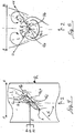
- a circular disc 1 is at an angle ⁇ against that in the Fig.1 From below coming streaming gas flow 2 inclined.
- the gas flow is deflected from its main flow direction and there is an overpressure area.
- the partial flow 2a of the gas flow stream 2 flows at a predetermined angle under the disc.
- a negative pressure area is formed, which is filled by the partial flow 2b of the gas flow rate over the edge of the disc. Due to the flow deflection at the edge of the disk, a horseshoe vortex 3 is formed with the vortex axis 3a shown in dashed lines, which continues in the form of a wake with two symmetrically rotating vortices downstream of the disk.
- the lateral vortices of the horseshoe vortex continue as wake vortices, interfere with the gas flow rate (basic flow) and spread with basic flow.
- the flow state within the wake is highly turbulent.
- the schematically illustrated boundary 3b of horseshoe vortices and vortices must not be understood as a sharp demarcation.
- the position and the structure of the, as well as the opposite directions of rotation of the two vortices can be determined experimentally by means of suitable measuring technology.
- the turbulent mixing of wake vortices and gas flow rate is used to evenly distribute a nearly punctually injected gas flow over a very large cross section.
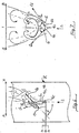
- two atomizing nozzles 4a and 4b are arranged on the head 4c of a nozzle lance 5 extending into a flue gas channel R.
- the atomizer nozzles are arranged on the lee side 1b of the preferably circular mixer disk 1 at a predetermined distance from it.
- the nozzle jet emerging from one of the nozzles 4a and 4b respectively contains gaseous components 6a and non-evaporated droplets 6b.
- the two atomizing nozzles 4a and 4b enclose an angle ⁇ of 120 ° and are inclined against the basic flow. Other angles are possible. The range between 60 ° and 120 ° is preferred.
- the plane spanned by the nozzles 4a and 4b is not inclined against the basic flow.
- the liquid reactant 5a is atomized by means of an atomization auxiliary medium 5c and the nozzle jet 6 is surrounded by barrier or curtain air 5c.
- Fig. 4-7 are schematically shown in addition to the partial flows 2a and 2b, the currents 6a (gaseous component of the jet 6) and 6b (unvaporized droplets) of the injection flow 6.
- the vaporized part 6a of the injection flow follows - as shown in the figures - the curvatures of the basic flow and is rolled into the vortex flow 3.
- the unvaporized droplets 6b follow their inertia below the selected Eindüswinkel ⁇ and thus penetrate on the lee side 1b of the disc 1 to the leeward - leading back vortex, so that a deposit formation of droplets and particulate matter from the flue gas is substantially avoided.
- the droplets of the partial stream 6b later evaporate in the outgas stream and are sufficiently mixed in by the turbulences present there.
- the partial stream 6a may also contain ultrafine droplets, but evaporate quickly and therefore contribute little to the formation of fouling, if at all. Based on the amount of reducing agent, the partial stream 6a contains substantially more reducing agent than the partial stream 6b. In the case of non-inventive penetration of the vortex pebbles, however, the smaller partial flow 6b would lead to considerable deposit formation.
- the nozzle head with the atomizer nozzles 4a and 4b upstream of the mixer disk 1 is arranged.
- the atomizer nozzles 4a and 4b are arranged so that the axes of the nozzle jets 6 extend on both sides at a sufficient distance next to the mixer disk 1.
- the distance to the disc may preferably be about 0.5 m.
- the droplet trajectories 6b penetrate the mixer disk to directed vortices.
- a plurality of mixer disks with associated atomizer nozzles can be provided distributed over the channel cross-section.
Landscapes
- Chemical & Material Sciences (AREA)
- Engineering & Computer Science (AREA)
- Chemical Kinetics & Catalysis (AREA)
- Environmental & Geological Engineering (AREA)
- General Chemical & Material Sciences (AREA)
- Biomedical Technology (AREA)
- Health & Medical Sciences (AREA)
- Analytical Chemistry (AREA)
- Oil, Petroleum & Natural Gas (AREA)
- Mechanical Engineering (AREA)
- General Engineering & Computer Science (AREA)
- Dispersion Chemistry (AREA)
- Treating Waste Gases (AREA)
- Nozzles (AREA)
- Chimneys And Flues (AREA)
- Gas Separation By Absorption (AREA)
Priority Applications (1)
| Application Number | Priority Date | Filing Date | Title |
|---|---|---|---|
| PL06829637T PL1962995T5 (pl) | 2005-12-15 | 2006-12-14 | Urządzenie do zmieszania płynu z dużym strumieniem gazu, zwłaszcza w celu wprowadzania środka redukującego do gazu spalinowego zawierającego tlenki azotu |
Applications Claiming Priority (2)
| Application Number | Priority Date | Filing Date | Title |
|---|---|---|---|
| DE102005059971A DE102005059971A1 (de) | 2005-12-15 | 2005-12-15 | Vorrichtung zum Vermischen eines Fluids mit einem großen Gasmengenstrom, insbesondere zum Einbringen eines Reduktionsmittels in ein Stickoxide enthaltendes Rauchgas |
| PCT/EP2006/012087 WO2007073881A1 (de) | 2005-12-15 | 2006-12-14 | Vorrichtung zum vermischen eines fluids mit einem grossen gasmengenstrom, insbesondere zum einbringen eines reduktionsmittels in ein stickoxide enthaltendes rauchgas |
Publications (3)
| Publication Number | Publication Date |
|---|---|
| EP1962995A1 EP1962995A1 (de) | 2008-09-03 |
| EP1962995B1 EP1962995B1 (de) | 2009-11-18 |
| EP1962995B2 true EP1962995B2 (de) | 2017-09-06 |
Family
ID=37859543
Family Applications (1)
| Application Number | Title | Priority Date | Filing Date |
|---|---|---|---|
| EP06829637.5A Active EP1962995B2 (de) | 2005-12-15 | 2006-12-14 | Vorrichtung zum vermischen eines fluids mit einem grossen gasmengenstrom, insbesondere zum einbringen eines reduktionsmittels in ein stickoxide enthaltendes rauchgas |
Country Status (10)
| Country | Link |
|---|---|
| US (1) | US8033531B2 (pl) |
| EP (1) | EP1962995B2 (pl) |
| CN (1) | CN101336130B (pl) |
| AT (1) | ATE448868T1 (pl) |
| DE (2) | DE102005059971A1 (pl) |
| ES (1) | ES2337089T5 (pl) |
| PL (1) | PL1962995T5 (pl) |
| RU (1) | RU2389537C2 (pl) |
| UA (1) | UA95937C2 (pl) |
| WO (1) | WO2007073881A1 (pl) |
Families Citing this family (13)
| Publication number | Priority date | Publication date | Assignee | Title |
|---|---|---|---|---|
| US8939638B2 (en) | 2008-04-21 | 2015-01-27 | Tenneco Automotive Operating Company Inc. | Method for mixing an exhaust gas flow |
| DE102008028625B4 (de) * | 2008-04-21 | 2011-12-15 | Tenneco Gmbh | Verfahren zum Vermischen eines Abgasstromes |
| US9095827B2 (en) | 2008-04-21 | 2015-08-04 | Tenneco Automotive Operating Company Inc. | Exhaust gas flow mixer |
| US8272777B2 (en) | 2008-04-21 | 2012-09-25 | Heinrich Gillet Gmbh (Tenneco) | Method for mixing an exhaust gas flow |
| CN101601965B (zh) * | 2009-07-24 | 2011-12-28 | 华电环保系统工程有限公司 | Scr法烟气脱硝的喷氨格栅装置,及scr法烟气脱硝工艺 |
| WO2014025538A1 (en) * | 2012-08-10 | 2014-02-13 | Tenneco Automotive Operating Company Inc. | Method for mixing an exhaust gas flow |
| DE202013103888U1 (de) | 2013-08-07 | 2013-09-08 | Radwan Matrmawi | Einrichtung zur chemischen und energetischen Verwertung von Rauchgas |
| CN105765193B (zh) * | 2013-11-26 | 2018-07-17 | 天纳克汽车经营有限公司 | 排气流混合器 |
| US9664082B2 (en) | 2014-06-02 | 2017-05-30 | Caterpillar Inc. | Reductant dosing system having staggered injectors |
| US9534525B2 (en) | 2015-05-27 | 2017-01-03 | Tenneco Automotive Operating Company Inc. | Mixer assembly for exhaust aftertreatment system |
| RU2633671C1 (ru) * | 2016-05-24 | 2017-10-16 | Андрей Юрьевич Беляев | Смеситель - турбулизатор |
| US11813548B2 (en) | 2018-04-12 | 2023-11-14 | Resource West, Inc. | Evaporator for ambient water bodies, and related system and method |
| DE102018005192B3 (de) | 2018-07-02 | 2019-12-05 | Truma Gerätetechnik GmbH & Co. KG | Brennervorrichtung |
Citations (3)
| Publication number | Priority date | Publication date | Assignee | Title |
|---|---|---|---|---|
| DD269101A1 (de) † | 1987-09-30 | 1989-06-21 | Orgreb Inst Kraftwerke | Vorrichtung zum intensiven vermischen von rauchgasen mit im gleichstrom gefuehrten additiven |
| EP0956897A2 (de) † | 1998-05-11 | 1999-11-17 | Deutsche Babcock Anlagen Gmbh | Vorrichtung zur Durchmischung eines einen Kanal Durchströmenden Gases |
| EP1166861A1 (de) † | 2000-06-19 | 2002-01-02 | Balcke-Dürr Energietechnik GmbH | Mischer für die Mischung mindestens zweier Gasströme oder anderer Newtonscher Flüssigkeiten |
Family Cites Families (23)
| Publication number | Priority date | Publication date | Assignee | Title |
|---|---|---|---|---|
| DE1071604B (pl) * | 1959-12-17 | |||
| US34586A (en) * | 1862-03-04 | Improvement in setting artificial teeth | ||
| DE434908C (de) | 1925-02-01 | 1926-10-05 | Abt Hoerder Ver | Verfahren zum Verlegen von Rohrstraengen |
| US2937013A (en) * | 1956-04-20 | 1960-05-17 | Ernest F Fisher | Water cooled deflectors used in fly ash suppression systems |
| NL151263B (nl) | 1966-06-22 | 1976-11-15 | Shell Int Research | Kokervormige vloeistof-gascontactinrichting. |
| FR1530772A (fr) * | 1966-06-22 | 1968-06-28 | Shell Int Research | Appareil pour la mise en contact intime de liquides et de vapeurs |
| US3317197A (en) * | 1966-06-22 | 1967-05-02 | Chemical Construction Corp | Stack mounted scrubber |
| US3957465A (en) * | 1972-05-12 | 1976-05-18 | Pircon Ladislav J | Pollution control apparatus and method |
| US4744958A (en) * | 1972-05-12 | 1988-05-17 | Pircon Ladislav J | Heterogeneous reactor |
| US3958961A (en) * | 1973-02-02 | 1976-05-25 | United States Filter Corporation | Wet electrostatic precipitators |
| US4358433A (en) * | 1976-04-16 | 1982-11-09 | Pircon Ladislav J | Heterogeneous process |
| US4070424A (en) * | 1976-09-21 | 1978-01-24 | Uop Inc. | Method and apparatus for conditioning flue gas with a mist of H2 SO4 |
| DE3043239C2 (de) * | 1980-11-15 | 1985-11-28 | Balcke-Dürr AG, 4030 Ratingen | Verfahren und Vorrichtung zum Vermischen mindestens zweier fluider Teilströme |
| GB8710685D0 (en) * | 1987-05-06 | 1987-06-10 | Turbotak Inc | Cluster nozzles |
| DE3723618C1 (en) * | 1987-07-17 | 1988-12-01 | Steinmueller Gmbh L & C | Apparatus for mixing two gases |
| DD277215A1 (de) | 1988-11-23 | 1990-03-28 | Orgreb Inst Kraftwerke | Vorrichtung zur verhinderung von additiv-anbackungen an einem pneumatisch betriebenen zweistoffduesensystem |
| SU1784260A1 (en) * | 1990-01-02 | 1992-12-30 | Proektno Izyskatelskij Nii Ukr | Gas refining device |
| DE4325968C2 (de) * | 1993-08-03 | 1997-04-10 | Balcke Duerr Ag | Vorrichtung zum Kühlen von Gasen und gegebenenfalls Trocknen von dem Gas zugegebenen Feststoffteilchen |
| DE4340908A1 (de) | 1993-12-01 | 1995-06-08 | Krc Umwelttechnik Gmbh | Verfahren und Vorrichtung zur Einbringung und gleichmäßigen Verteilung von adsorbierenden Feststoffen in einen Rauchgasstrom |
| DE19855338A1 (de) * | 1998-12-01 | 2000-06-08 | Bosch Gmbh Robert | Vorrichtung zum Einbringen eines Reduktionsmittels in einen Abgasrohrabschnitt einer Brennkraftmaschine |
| DE19929765A1 (de) * | 1999-06-29 | 2001-01-11 | Siemens Ag | Reinigungseinrichtung für Rauchgas |
| DE19962616A1 (de) * | 1999-12-23 | 2001-06-28 | Basf Ag | Verfahren und Vorrichtung zur Erzeugung eines homogenen Gemisches aus einem dampfförmigen aromatischen Kohlenwasserstoff und einem Sauerstoff enthaltenden Gas |
| EP1681090B1 (de) * | 2005-01-17 | 2007-05-30 | Balcke-Dürr GmbH | Vorrichtung und Verfahren zum Mischen eines Fluidstroms in einem Strömungskanal |
-
2005
- 2005-12-15 DE DE102005059971A patent/DE102005059971A1/de not_active Ceased
-
2006
- 2006-12-14 ES ES06829637.5T patent/ES2337089T5/es active Active
- 2006-12-14 DE DE502006005425T patent/DE502006005425D1/de active Active
- 2006-12-14 WO PCT/EP2006/012087 patent/WO2007073881A1/de not_active Ceased
- 2006-12-14 CN CN2006800519638A patent/CN101336130B/zh not_active Expired - Fee Related
- 2006-12-14 PL PL06829637T patent/PL1962995T5/pl unknown
- 2006-12-14 UA UAA200809268A patent/UA95937C2/ru unknown
- 2006-12-14 RU RU2008128855/15A patent/RU2389537C2/ru active
- 2006-12-14 EP EP06829637.5A patent/EP1962995B2/de active Active
- 2006-12-14 AT AT06829637T patent/ATE448868T1/de not_active IP Right Cessation
- 2006-12-14 US US12/097,435 patent/US8033531B2/en active Active
Patent Citations (3)
| Publication number | Priority date | Publication date | Assignee | Title |
|---|---|---|---|---|
| DD269101A1 (de) † | 1987-09-30 | 1989-06-21 | Orgreb Inst Kraftwerke | Vorrichtung zum intensiven vermischen von rauchgasen mit im gleichstrom gefuehrten additiven |
| EP0956897A2 (de) † | 1998-05-11 | 1999-11-17 | Deutsche Babcock Anlagen Gmbh | Vorrichtung zur Durchmischung eines einen Kanal Durchströmenden Gases |
| EP1166861A1 (de) † | 2000-06-19 | 2002-01-02 | Balcke-Dürr Energietechnik GmbH | Mischer für die Mischung mindestens zweier Gasströme oder anderer Newtonscher Flüssigkeiten |
Also Published As
| Publication number | Publication date |
|---|---|
| DE102005059971A1 (de) | 2007-06-21 |
| CN101336130A (zh) | 2008-12-31 |
| WO2007073881A1 (de) | 2007-07-05 |
| DE502006005425D1 (de) | 2009-12-31 |
| ATE448868T1 (de) | 2009-12-15 |
| PL1962995T3 (pl) | 2010-06-30 |
| PL1962995T5 (pl) | 2018-04-30 |
| US8033531B2 (en) | 2011-10-11 |
| ES2337089T3 (es) | 2010-04-20 |
| ES2337089T5 (es) | 2017-12-26 |
| RU2008128855A (ru) | 2010-01-20 |
| US20080308955A1 (en) | 2008-12-18 |
| RU2389537C2 (ru) | 2010-05-20 |
| CN101336130B (zh) | 2011-09-07 |
| EP1962995B1 (de) | 2009-11-18 |
| EP1962995A1 (de) | 2008-09-03 |
| UA95937C2 (ru) | 2011-09-26 |
Similar Documents
| Publication | Publication Date | Title |
|---|---|---|
| EP1956206B1 (de) | Abgasreinigungssystem | |
| EP0637726B1 (de) | Vorrichtung zum Kühlen von Gasen und ggf. Trocknen von dem Gas zugegebenen Feststoffteilchen | |
| EP1962995B2 (de) | Vorrichtung zum vermischen eines fluids mit einem grossen gasmengenstrom, insbesondere zum einbringen eines reduktionsmittels in ein stickoxide enthaltendes rauchgas | |
| EP1981621B1 (de) | Verfahren und vorrichtung zum vermischen eines gasförmigen fluids mit einem grossen gasmengenstrom, insbesondere zum einbringen eines reduktionsmittels in ein stickoxide enthaltendes rauchgas | |
| EP2969234B1 (de) | Zerstäuberdüse für einen sanitären wasserauslauf sowie sanitäre auslaufarmatur mit einem wasserauslauf | |
| EP2190587B1 (de) | Vielloch- oder bündeldüse | |
| EP2456963B1 (de) | Einspritzdüse zur zufuhr von reduktionsmittel und vorrichtung zur behandlung von abgasen | |
| DE3728557C2 (pl) | ||
| WO2008135112A1 (de) | Vorrichtung und verfahren zur zudosierung von fluiden schadstoffreduzierenden medien in einen abgaskanal einer brennkraftmaschine | |
| DE3131070A1 (de) | "spruehduese mit hohem wirkungsgrad" | |
| EP1404949A1 (de) | Mischeinrichtung für eine abgasreinigungsanlage | |
| DE3419423A1 (de) | Spruehduese | |
| EP2956639A1 (de) | Abgasleitungsabschnitt zur zufuhr von flüssigem additiv | |
| EP1981622B1 (de) | Verfahren und vorrichtung zum vermischen eines gasförmigen fluids mit einem grossen gasmengenstrom, insbesondere zum einbringen eines reduktionsmittels in ein stickoxide enthaltendes rauchgas | |
| DE102008008563A1 (de) | Dosiervorrichtung zur Schadstoffverminderung in Abgasen | |
| DE19758526B4 (de) | Drallsprühdüse | |
| DE2711726C2 (de) | Vorrichtung zum Zerstäuben einer Flüssigkeit, insbesondere für die Melaminherstellung und die Harnstoffgranulatherstellung | |
| EP0751820A1 (de) | Kombinierte einbring- und mischvorrichtung | |
| EP0670986A1 (de) | Mischvorrichtung | |
| EP3152420B1 (de) | Einspritzmodul und abgasstrang mit einspritzmodul | |
| EP3068986B1 (de) | Einspritzmodul und abgasstrang mit einspritzmodul | |
| DE112015004193T5 (de) | Vertikales Ultraschallzersetzungsrohr | |
| DE202014101462U1 (de) | Vorrichtung zur Erzeugung von Flüssigkeitsnebel | |
| DE102008028171A1 (de) | Düseneinrichtung und Verfahren zum Zuführen eines Hilfsmittels in einen Abgasstrom einer Verbrennungskraftmaschine | |
| DE102015201109A1 (de) | Spritzlochscheibe und Einspritzventil mit Spritzlochscheibe |
Legal Events
| Date | Code | Title | Description |
|---|---|---|---|
| PUAI | Public reference made under article 153(3) epc to a published international application that has entered the european phase |
Free format text: ORIGINAL CODE: 0009012 |
|
| 17P | Request for examination filed |
Effective date: 20080701 |
|
| AK | Designated contracting states |
Kind code of ref document: A1 Designated state(s): AT BE BG CH CY CZ DE DK EE ES FI FR GB GR HU IE IS IT LI LT LU LV MC NL PL PT RO SE SI SK TR |
|
| GRAP | Despatch of communication of intention to grant a patent |
Free format text: ORIGINAL CODE: EPIDOSNIGR1 |
|
| GRAS | Grant fee paid |
Free format text: ORIGINAL CODE: EPIDOSNIGR3 |
|
| GRAA | (expected) grant |
Free format text: ORIGINAL CODE: 0009210 |
|
| AK | Designated contracting states |
Kind code of ref document: B1 Designated state(s): AT BE BG CH CY CZ DE DK EE ES FI FR GB GR HU IE IS IT LI LT LU LV MC NL PL PT RO SE SI SK TR |
|
| REG | Reference to a national code |
Ref country code: GB Ref legal event code: FG4D Free format text: NOT ENGLISH |
|
| REG | Reference to a national code |
Ref country code: CH Ref legal event code: EP |
|
| REG | Reference to a national code |
Ref country code: IE Ref legal event code: FG4D |
|
| REF | Corresponds to: |
Ref document number: 502006005425 Country of ref document: DE Date of ref document: 20091231 Kind code of ref document: P |
|
| REG | Reference to a national code |
Ref country code: NL Ref legal event code: VDEP Effective date: 20091118 |
|
| REG | Reference to a national code |
Ref country code: ES Ref legal event code: FG2A Ref document number: 2337089 Country of ref document: ES Kind code of ref document: T3 |
|
| LTIE | Lt: invalidation of european patent or patent extension |
Effective date: 20091118 |
|
| PG25 | Lapsed in a contracting state [announced via postgrant information from national office to epo] |
Ref country code: SE Free format text: LAPSE BECAUSE OF FAILURE TO SUBMIT A TRANSLATION OF THE DESCRIPTION OR TO PAY THE FEE WITHIN THE PRESCRIBED TIME-LIMIT Effective date: 20091118 Ref country code: LT Free format text: LAPSE BECAUSE OF FAILURE TO SUBMIT A TRANSLATION OF THE DESCRIPTION OR TO PAY THE FEE WITHIN THE PRESCRIBED TIME-LIMIT Effective date: 20091118 Ref country code: FI Free format text: LAPSE BECAUSE OF FAILURE TO SUBMIT A TRANSLATION OF THE DESCRIPTION OR TO PAY THE FEE WITHIN THE PRESCRIBED TIME-LIMIT Effective date: 20091118 Ref country code: PT Free format text: LAPSE BECAUSE OF FAILURE TO SUBMIT A TRANSLATION OF THE DESCRIPTION OR TO PAY THE FEE WITHIN THE PRESCRIBED TIME-LIMIT Effective date: 20100318 Ref country code: IS Free format text: LAPSE BECAUSE OF FAILURE TO SUBMIT A TRANSLATION OF THE DESCRIPTION OR TO PAY THE FEE WITHIN THE PRESCRIBED TIME-LIMIT Effective date: 20100318 |
|
| PG25 | Lapsed in a contracting state [announced via postgrant information from national office to epo] |
Ref country code: SI Free format text: LAPSE BECAUSE OF FAILURE TO SUBMIT A TRANSLATION OF THE DESCRIPTION OR TO PAY THE FEE WITHIN THE PRESCRIBED TIME-LIMIT Effective date: 20091118 Ref country code: LV Free format text: LAPSE BECAUSE OF FAILURE TO SUBMIT A TRANSLATION OF THE DESCRIPTION OR TO PAY THE FEE WITHIN THE PRESCRIBED TIME-LIMIT Effective date: 20091118 Ref country code: CY Free format text: LAPSE BECAUSE OF FAILURE TO SUBMIT A TRANSLATION OF THE DESCRIPTION OR TO PAY THE FEE WITHIN THE PRESCRIBED TIME-LIMIT Effective date: 20091118 |
|
| REG | Reference to a national code |
Ref country code: IE Ref legal event code: FD4D |
|
| BERE | Be: lapsed |
Owner name: FISIA BABCOCK ENVIRONMENT G.M.B.H. Effective date: 20091231 |
|
| PG25 | Lapsed in a contracting state [announced via postgrant information from national office to epo] |
Ref country code: MC Free format text: LAPSE BECAUSE OF NON-PAYMENT OF DUE FEES Effective date: 20100701 Ref country code: IE Free format text: LAPSE BECAUSE OF FAILURE TO SUBMIT A TRANSLATION OF THE DESCRIPTION OR TO PAY THE FEE WITHIN THE PRESCRIBED TIME-LIMIT Effective date: 20091118 Ref country code: EE Free format text: LAPSE BECAUSE OF FAILURE TO SUBMIT A TRANSLATION OF THE DESCRIPTION OR TO PAY THE FEE WITHIN THE PRESCRIBED TIME-LIMIT Effective date: 20091118 Ref country code: BG Free format text: LAPSE BECAUSE OF FAILURE TO SUBMIT A TRANSLATION OF THE DESCRIPTION OR TO PAY THE FEE WITHIN THE PRESCRIBED TIME-LIMIT Effective date: 20100218 Ref country code: NL Free format text: LAPSE BECAUSE OF FAILURE TO SUBMIT A TRANSLATION OF THE DESCRIPTION OR TO PAY THE FEE WITHIN THE PRESCRIBED TIME-LIMIT Effective date: 20091118 Ref country code: DK Free format text: LAPSE BECAUSE OF FAILURE TO SUBMIT A TRANSLATION OF THE DESCRIPTION OR TO PAY THE FEE WITHIN THE PRESCRIBED TIME-LIMIT Effective date: 20091118 Ref country code: RO Free format text: LAPSE BECAUSE OF FAILURE TO SUBMIT A TRANSLATION OF THE DESCRIPTION OR TO PAY THE FEE WITHIN THE PRESCRIBED TIME-LIMIT Effective date: 20091118 |
|
| PLBI | Opposition filed |
Free format text: ORIGINAL CODE: 0009260 |
|
| PG25 | Lapsed in a contracting state [announced via postgrant information from national office to epo] |
Ref country code: CZ Free format text: LAPSE BECAUSE OF FAILURE TO SUBMIT A TRANSLATION OF THE DESCRIPTION OR TO PAY THE FEE WITHIN THE PRESCRIBED TIME-LIMIT Effective date: 20091118 Ref country code: SK Free format text: LAPSE BECAUSE OF FAILURE TO SUBMIT A TRANSLATION OF THE DESCRIPTION OR TO PAY THE FEE WITHIN THE PRESCRIBED TIME-LIMIT Effective date: 20091118 |
|
| PLAX | Notice of opposition and request to file observation + time limit sent |
Free format text: ORIGINAL CODE: EPIDOSNOBS2 |
|
| REG | Reference to a national code |
Ref country code: FR Ref legal event code: ST Effective date: 20100831 |
|
| 26 | Opposition filed |
Opponent name: BALCKE-DUERR GMBH Effective date: 20100818 |
|
| PG25 | Lapsed in a contracting state [announced via postgrant information from national office to epo] |
Ref country code: GR Free format text: LAPSE BECAUSE OF FAILURE TO SUBMIT A TRANSLATION OF THE DESCRIPTION OR TO PAY THE FEE WITHIN THE PRESCRIBED TIME-LIMIT Effective date: 20100219 Ref country code: FR Free format text: LAPSE BECAUSE OF NON-PAYMENT OF DUE FEES Effective date: 20100118 Ref country code: BE Free format text: LAPSE BECAUSE OF NON-PAYMENT OF DUE FEES Effective date: 20091231 |
|
| PLAF | Information modified related to communication of a notice of opposition and request to file observations + time limit |
Free format text: ORIGINAL CODE: EPIDOSCOBS2 |
|
| PLBB | Reply of patent proprietor to notice(s) of opposition received |
Free format text: ORIGINAL CODE: EPIDOSNOBS3 |
|
| PG25 | Lapsed in a contracting state [announced via postgrant information from national office to epo] |
Ref country code: LU Free format text: LAPSE BECAUSE OF NON-PAYMENT OF DUE FEES Effective date: 20091214 |
|
| PG25 | Lapsed in a contracting state [announced via postgrant information from national office to epo] |
Ref country code: AT Free format text: LAPSE BECAUSE OF NON-PAYMENT OF DUE FEES Effective date: 20091214 |
|
| PG25 | Lapsed in a contracting state [announced via postgrant information from national office to epo] |
Ref country code: HU Free format text: LAPSE BECAUSE OF FAILURE TO SUBMIT A TRANSLATION OF THE DESCRIPTION OR TO PAY THE FEE WITHIN THE PRESCRIBED TIME-LIMIT Effective date: 20100519 |
|
| REG | Reference to a national code |
Ref country code: CH Ref legal event code: PL |
|
| PG25 | Lapsed in a contracting state [announced via postgrant information from national office to epo] |
Ref country code: TR Free format text: LAPSE BECAUSE OF FAILURE TO SUBMIT A TRANSLATION OF THE DESCRIPTION OR TO PAY THE FEE WITHIN THE PRESCRIBED TIME-LIMIT Effective date: 20091118 |
|
| PG25 | Lapsed in a contracting state [announced via postgrant information from national office to epo] |
Ref country code: CH Free format text: LAPSE BECAUSE OF NON-PAYMENT OF DUE FEES Effective date: 20101231 Ref country code: LI Free format text: LAPSE BECAUSE OF NON-PAYMENT OF DUE FEES Effective date: 20101231 |
|
| RIC2 | Information provided on ipc code assigned after grant |
Ipc: B29K 67/00 20060101AFI20120613BHEP |
|
| APBM | Appeal reference recorded |
Free format text: ORIGINAL CODE: EPIDOSNREFNO |
|
| APBP | Date of receipt of notice of appeal recorded |
Free format text: ORIGINAL CODE: EPIDOSNNOA2O |
|
| APAH | Appeal reference modified |
Free format text: ORIGINAL CODE: EPIDOSCREFNO |
|
| PG25 | Lapsed in a contracting state [announced via postgrant information from national office to epo] |
Ref country code: IT Free format text: LAPSE BECAUSE OF NON-PAYMENT OF DUE FEES Effective date: 20121214 |
|
| REG | Reference to a national code |
Ref country code: DE Ref legal event code: R082 Ref document number: 502006005425 Country of ref document: DE Representative=s name: WAGNER & GEYER PARTNERSCHAFT PATENT- UND RECHT, DE Ref country code: DE Ref legal event code: R082 Ref document number: 502006005425 Country of ref document: DE Representative=s name: WAGNER & GEYER PARTNERSCHAFT MBB PATENT- UND R, DE |
|
| PGRI | Patent reinstated in contracting state [announced from national office to epo] |
Ref country code: IT Effective date: 20150209 |
|
| APBU | Appeal procedure closed |
Free format text: ORIGINAL CODE: EPIDOSNNOA9O |
|
| PUAH | Patent maintained in amended form |
Free format text: ORIGINAL CODE: 0009272 |
|
| STAA | Information on the status of an ep patent application or granted ep patent |
Free format text: STATUS: PATENT MAINTAINED AS AMENDED |
|
| 27A | Patent maintained in amended form |
Effective date: 20170906 |
|
| AK | Designated contracting states |
Kind code of ref document: B2 Designated state(s): AT BE BG CH CY CZ DE DK EE ES FI FR GB GR HU IE IS IT LI LT LU LV MC NL PL PT RO SE SI SK TR |
|
| REG | Reference to a national code |
Ref country code: DE Ref legal event code: R102 Ref document number: 502006005425 Country of ref document: DE |
|
| REG | Reference to a national code |
Ref country code: ES Ref legal event code: DC2A Ref document number: 2337089 Country of ref document: ES Kind code of ref document: T5 Effective date: 20171226 |
|
| REG | Reference to a national code |
Ref country code: DE Ref legal event code: R079 Ref document number: 502006005425 Country of ref document: DE Free format text: PREVIOUS MAIN CLASS: B01F0003040000 Ipc: B01F0023200000 |
|
| REG | Reference to a national code |
Ref country code: DE Ref legal event code: R082 Ref document number: 502006005425 Country of ref document: DE Representative=s name: ADVOPAT PATENT- UND RECHTSANWAELTE, DE |
|
| PGFP | Annual fee paid to national office [announced via postgrant information from national office to epo] |
Ref country code: GB Payment date: 20231220 Year of fee payment: 18 |
|
| PGFP | Annual fee paid to national office [announced via postgrant information from national office to epo] |
Ref country code: PL Payment date: 20231205 Year of fee payment: 18 |
|
| PGFP | Annual fee paid to national office [announced via postgrant information from national office to epo] |
Ref country code: ES Payment date: 20240118 Year of fee payment: 18 |
|
| PGFP | Annual fee paid to national office [announced via postgrant information from national office to epo] |
Ref country code: DE Payment date: 20240209 Year of fee payment: 18 |
|
| PGFP | Annual fee paid to national office [announced via postgrant information from national office to epo] |
Ref country code: IT Payment date: 20231229 Year of fee payment: 18 |
|
| REG | Reference to a national code |
Ref country code: DE Ref legal event code: R119 Ref document number: 502006005425 Country of ref document: DE |
|
| GBPC | Gb: european patent ceased through non-payment of renewal fee |
Effective date: 20241214 |
|
| PG25 | Lapsed in a contracting state [announced via postgrant information from national office to epo] |
Ref country code: DE Free format text: LAPSE BECAUSE OF NON-PAYMENT OF DUE FEES Effective date: 20250701 |
|
| PG25 | Lapsed in a contracting state [announced via postgrant information from national office to epo] |
Ref country code: GB Free format text: LAPSE BECAUSE OF NON-PAYMENT OF DUE FEES Effective date: 20241214 |