EP1962394B1 - Appareil de multiplexage à division de longueur d'onde - Google Patents
Appareil de multiplexage à division de longueur d'onde Download PDFInfo
- Publication number
- EP1962394B1 EP1962394B1 EP08158020A EP08158020A EP1962394B1 EP 1962394 B1 EP1962394 B1 EP 1962394B1 EP 08158020 A EP08158020 A EP 08158020A EP 08158020 A EP08158020 A EP 08158020A EP 1962394 B1 EP1962394 B1 EP 1962394B1
- Authority
- EP
- European Patent Office
- Prior art keywords
- optical
- wavelength
- light
- attenuation
- optical signals
- Prior art date
- Legal status (The legal status is an assumption and is not a legal conclusion. Google has not performed a legal analysis and makes no representation as to the accuracy of the status listed.)
- Expired - Lifetime
Links
- 230000003287 optical effect Effects 0.000 claims description 67
- 238000012806 monitoring device Methods 0.000 claims 2
- 238000012544 monitoring process Methods 0.000 claims 1
- 238000001228 spectrum Methods 0.000 description 8
- 238000010586 diagram Methods 0.000 description 7
- 238000005259 measurement Methods 0.000 description 3
- 230000010287 polarization Effects 0.000 description 3
- 230000002238 attenuated effect Effects 0.000 description 2
- 230000005540 biological transmission Effects 0.000 description 2
- 238000001514 detection method Methods 0.000 description 2
- 239000013307 optical fiber Substances 0.000 description 2
- 230000003321 amplification Effects 0.000 description 1
- 239000000470 constituent Substances 0.000 description 1
- 238000001816 cooling Methods 0.000 description 1
- 238000010438 heat treatment Methods 0.000 description 1
- 238000003199 nucleic acid amplification method Methods 0.000 description 1
- 230000010355 oscillation Effects 0.000 description 1
Images


Classifications
-
- H—ELECTRICITY
- H04—ELECTRIC COMMUNICATION TECHNIQUE
- H04B—TRANSMISSION
- H04B10/00—Transmission systems employing electromagnetic waves other than radio-waves, e.g. infrared, visible or ultraviolet light, or employing corpuscular radiation, e.g. quantum communication
- H04B10/29—Repeaters
- H04B10/291—Repeaters in which processing or amplification is carried out without conversion of the main signal from optical form
- H04B10/293—Signal power control
- H04B10/294—Signal power control in a multiwavelength system, e.g. gain equalisation
- H04B10/296—Transient power control, e.g. due to channel add/drop or rapid fluctuations in the input power
-
- H—ELECTRICITY
- H04—ELECTRIC COMMUNICATION TECHNIQUE
- H04B—TRANSMISSION
- H04B10/00—Transmission systems employing electromagnetic waves other than radio-waves, e.g. infrared, visible or ultraviolet light, or employing corpuscular radiation, e.g. quantum communication
- H04B10/50—Transmitters
- H04B10/564—Power control
-
- H—ELECTRICITY
- H04—ELECTRIC COMMUNICATION TECHNIQUE
- H04J—MULTIPLEX COMMUNICATION
- H04J14/00—Optical multiplex systems
- H04J14/02—Wavelength-division multiplex systems
-
- H—ELECTRICITY
- H04—ELECTRIC COMMUNICATION TECHNIQUE
- H04J—MULTIPLEX COMMUNICATION
- H04J14/00—Optical multiplex systems
- H04J14/02—Wavelength-division multiplex systems
- H04J14/0221—Power control, e.g. to keep the total optical power constant
-
- H—ELECTRICITY
- H04—ELECTRIC COMMUNICATION TECHNIQUE
- H04J—MULTIPLEX COMMUNICATION
- H04J14/00—Optical multiplex systems
- H04J14/02—Wavelength-division multiplex systems
- H04J14/0221—Power control, e.g. to keep the total optical power constant
- H04J14/02216—Power control, e.g. to keep the total optical power constant by gain equalization
Definitions
- the present invention relates to a wavelength division multiplexing (WDM) apparatus that combines a plurality of optical signals of different wavelengths and optically amplifies the combined signal.
- WDM apparatuses are classified into two types: a non-transponder type which takes as inputs a plurality of narrowband optical signals of different wavelengths, combines them together, and optically amplifies the combined signal; and a transponder type which has at its front end a plurality of transponders that respectively convert a plurality of wideband optical signals of the same wavelength into a plurality of narrowband optical signals of different wavelengths.
- the present invention concerns a transponder type WDM apparatus.
- a prior art non-transponder-type WDM apparatus comprises a plurality of variable attenuators which respectively attenuate a plurality of optical signals of different wavelengths with variable attenuation ratios, an optical combiner which combines the optical outputs of the attenuators, and an optical amplifier which optically amplifies the optical output of the optical combiner.
- the spectrum of the output light is measured with a spectrum analyzer unit and, based on the result of the measurement, each individual variable attenuator is controlled to suppress a variation (tilt) in the output level of each wavelength. If a wavelength deviation greater than an allowable level is detected from the result of the spectrum measurement, the amount of attenuation for that wavelength is set to a maximum to prevent it from affecting its adjacent wavelengths.
- the plurality of variable attenuators are preceded by a plurality of transponders that respectively convert a plurality of optical signals of the same wavelength into a plurality of optical signals of different wavelengths.
- the prior art non-transponder-type WDM apparatus and transponder-type WDM apparatus will be described in detail, later, with reference to the drawings.
- a second problem with the prior art WDM apparatus concerns the accuracy of each wavelength in the output light.
- wavelength deviation of each wavelength is monitored with a spectrum analyzer, with provisions made so that if a wavelength deviation greater than an allowable level is detected for any wavelength, the amount of attenuation for that wavelength is set to a maximum to prevent it from affecting its adjacent wavelengths.
- the spectrum analyzer has the problem that its wavelength resolution is poor and measurements cannot be made with high accuracy.
- Another problem is that since the wavelength is swept, it takes several tens of seconds from the time a wavelength deviation occurs until the time it is detected, this giving rise to the possibility that an error may be caused in adjacent wavelengths during that time.
- JP 07 030 520 discloses an optical fiber amplifier for wavelength multiplex transmission, wherein n sets of signal lights whose wavelength differs from each other are individually attenuated by optical attenuators and subjected to wavelength multiplexing at an optical multiplexer.
- the multiplexed signal is amplified by an optical fiber amplifier and the amplified signal is outputted, the part is branched and used for feedback control.
- the signal light branched into wavelengths ⁇ 1 - ⁇ n at an optical branching device is converted into an electric signal by n optoelectric converters.
- Attenuation rate controllers compare the optical output level of each signal light represented in the electric signal with a desired optical output level to individually control the attenuation rate of the optical attenuators.
- JP 07 007 212 discloses an apparatus for controlling wavelength of light emitted from laser diode having a means which splits the light emitted from a laser diode into two light beams, a pair of optical bandpass filters which transmit the split light beams, respectively, means which output the electric signals corresponding to the amounts of the transmitted light through the optical bandpass filters, a comparing means which compares the output signals and outputs the control signal based on the difference between both signals, and a means which controls the temperature of the laser diode.
- the central wavelengths of the pair of optical bandpass filters are set on the short wavelength side and the long wavelength side between which the wavelength of the light emission center of the laser diode exists, respectively. When the wavelength of the light emission center of the laser diode is deviated, the difference is generated between the amounts of the received light in optical bandpass filters. The temperature of the laser diode is controlled so that the difference becomes zero.
- a first object of the present invention is to provide a WDM apparatus that is not affected by light leaking from an unused wavelength.
- a second object of the present invention is to provide a WDM apparatus that can take corrective action by quickly and accurately detecting a wavelength deviation.
- a wavelength division multiplexing apparatus according to Claim 1.
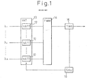
- FIG. 1 shows the configuration of a non-transponder-type WDM apparatus according to the prior art.
- An optical variable attenuation section (VAT) 10 includes a number, n, of optical variable attenuators (VATTs) 12.
- Optical signals of different wavelengths ⁇ 1 , ..., ⁇ i , ..., ⁇ n are input to the respective optical variable attenuators 12.
- Outputs of the optical variable attenuators 12 are combined in a transmitting wave multiplexer (TWM) 14 and optically amplified in a transmitting wave amplifier (TWA) 16.
- TWM transmitting wave multiplexer
- TWA transmitting wave amplifier
- a spectrum analyzer unit (SAU) 18 measures the spectrum of the optical output of the TWA 16 and outputs a signal to control each VATT 12 so that the optical power level of each wavelength will be maintained at a predetermined level. If a wavelength deviation greater than an allowable level is detected, the amount of attenuation in the corresponding VATT 12 is set to a maximum.
- FIG. 2 shows the configuration of a transponder-type WDM apparatus according to the prior art.
- the same constituent elements as those in Figure 1 are designated by the same reference numerals, and their descriptions will not be repeated.
- the number, n, of transponders (TPs) 20 which respectively convert the number, n, of relatively wideband optical signals of equal wavelength ⁇ a into the number, n, of narrowband optical signals of different wavelengths ⁇ 1 ..., ⁇ i , ..., ⁇ n are arranged in front of the VAT 10.
- Figure 3 shows the details of each TP 20.
- the input optical signal of wavelength ⁇ a is first converted by an optical-to-electrical converter 22 into an electrical signal, and then converted by a narrowband electrical-to-optical converter (narrowband laser diode) 24 into an optical signal of wavelength ⁇ i .
- the wavelength of the optical output is controlled by heating or cooling the laser diode with a Peltier element 28.
- a wavelength locker 26 monitors the wavelength of the optical output, and supplies the appropriate control signal to the Peltier element 28 to lock the wavelength of the optical output at a predetermined value.
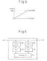
- Figure 4 shows an optical variable attenuator using a Faraday rotator, as one example of the VATT.
- input light is passed through the Faraday rotator 30 and output via a polarizer 32.
- An electromagnet 34 is energized to apply a magnetic field to the Faraday rotator 30 in a direction parallel to its optical axis.
- the strength of the magnetic field developed in the direction parallel to the optical axis of the Faraday rotator 30 varies, thereby rotating the plane of polarization of the light passing through the Faraday rotator.
- Figure 5 shows the relationship between the current and the amount of attenuation in the optical variable attenuator of Figure 4 .
- the amount of attenuation that the optical variable attenuator of the type shown in Figure 4 can achieve is 20 dB at maximum.
- Figure 6 shows the details of the wavelength locker 26 contained in the transponder of Figure 3 .
- part of the input light is separated and transmitted through optical filters 36 and 38, and the transmitted light is detected by photodiodes 40 and 42 which then supply their detection results to a calculation unit 44.
- the optical filters 36 and 38 have wavelength characteristics centered about f 0 minus several tens of ppm (indicated by "A” in Figures 7A and 7B ) and f 0 plus several tens of ppm (indicated by "B” in Figures 7A and 7B ), respectively, where f 0 is the desired wavelength.
- f 0 is the desired wavelength.
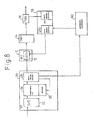
- Figure 8 shows a WDM apparatus according to an embodiment of the present invention, which can take corrective action by quickly and accurately detecting a wavelength deviation.
- the SAU 18 monitors the spectrum of the output light and, if a wavelength deviation is detected, sets the amount of attenuation maximum for that wavelength.
- the embodiment of the present invention uses, in addition to the above-described control, the detection of a wavelength deviation performed in the wavelength locker 26. More specifically, as explained with reference to Figures 6 , 7A, and 7B , the absolute value of (a - b), i.e., the difference between the optical power of the light transmitted through the optical filter 36 and that of the light transmitted through the optical filter 38, represents the magnitude of the wavelength deviation.
- the apparatus controller 60 receives this value from the wavelength locker 26 and, if this value exceeds a predetermined value, then determines that the wavelength deviation has exceeded the allowable level and instructs the SAU 18 to set the amount of attenuation in the corresponding VATT 12 to a maximum value.
Landscapes
- Engineering & Computer Science (AREA)
- Computer Networks & Wireless Communication (AREA)
- Signal Processing (AREA)
- Physics & Mathematics (AREA)
- Electromagnetism (AREA)
- Optical Communication System (AREA)
- Lasers (AREA)
Claims (1)
- Dispositif de multiplexage par répartition en longueur d'onde comprenant :une pluralité de transpondeurs (20) pour convertir respectivement une pluralité de signaux optiques de la même longueur d'onde en une pluralité de signaux optiques de différentes longueurs d'onde ;une pluralité d'atténuateurs variables (12) pour recevoir la pluralité de signaux optiques de différentes longueurs d'onde respectivement, et pour atténuer respectivement les signaux optiques d'entrée avec des quantités variables d'atténuation ;un combineur optique (14) pour combiner les sorties optiques de la pluralité d'atténuateurs variables ;un amplificateur optique (16) pour amplifier optiquement une sortie optique du combineur optique,caractérisé en ce qu'il comprend en outre :un dispositif de surveillance de longueur d'onde (26), prévu dans chacun des transpondeurs (20), pour surveiller le signal optique sorti de celui-ci quant à un écart de longueur d'onde ; etun contrôleur (60) agencé pour fixer la quantité d'atténuation à une valeur maximum pour l'atténuateur optique (12) correspondant au signal optique qui a été détecté par le dispositif de surveillance de longueur d'onde (26) comme ayant un écart de longueur d'onde supérieur à une valeur prédéterminée.
Priority Applications (1)
| Application Number | Priority Date | Filing Date | Title |
|---|---|---|---|
| DE69941865T DE69941865D1 (de) | 1999-08-23 | 1999-08-23 | Multiplexing-Vorrichtung zur Wellenlängentrennung |
Applications Claiming Priority (2)
| Application Number | Priority Date | Filing Date | Title |
|---|---|---|---|
| EP99938592A EP1211763B1 (fr) | 1999-08-23 | 1999-08-23 | Multiplexeur de longueur d'onde |
| PCT/JP1999/004534 WO2001015291A1 (fr) | 1999-08-23 | 1999-08-23 | Multiplexeur de longueur d'onde |
Related Parent Applications (1)
| Application Number | Title | Priority Date | Filing Date |
|---|---|---|---|
| EP99938592A Division EP1211763B1 (fr) | 1999-08-23 | 1999-08-23 | Multiplexeur de longueur d'onde |
Publications (3)
| Publication Number | Publication Date |
|---|---|
| EP1962394A2 EP1962394A2 (fr) | 2008-08-27 |
| EP1962394A3 EP1962394A3 (fr) | 2008-09-17 |
| EP1962394B1 true EP1962394B1 (fr) | 2009-12-23 |
Family
ID=14236525
Family Applications (2)
| Application Number | Title | Priority Date | Filing Date |
|---|---|---|---|
| EP08158020A Expired - Lifetime EP1962394B1 (fr) | 1999-08-23 | 1999-08-23 | Appareil de multiplexage à division de longueur d'onde |
| EP99938592A Expired - Lifetime EP1211763B1 (fr) | 1999-08-23 | 1999-08-23 | Multiplexeur de longueur d'onde |
Family Applications After (1)
| Application Number | Title | Priority Date | Filing Date |
|---|---|---|---|
| EP99938592A Expired - Lifetime EP1211763B1 (fr) | 1999-08-23 | 1999-08-23 | Multiplexeur de longueur d'onde |
Country Status (5)
| Country | Link |
|---|---|
| US (1) | US6707963B2 (fr) |
| EP (2) | EP1962394B1 (fr) |
| JP (1) | JP4107841B2 (fr) |
| DE (2) | DE69941865D1 (fr) |
| WO (1) | WO2001015291A1 (fr) |
Families Citing this family (12)
| Publication number | Priority date | Publication date | Assignee | Title |
|---|---|---|---|---|
| GB2378525A (en) * | 2001-08-08 | 2003-02-12 | Bookham Technology Plc | Optic system |
| JP3976554B2 (ja) * | 2001-11-28 | 2007-09-19 | 富士通株式会社 | 可変減衰器制御システム |
| JP3986824B2 (ja) * | 2001-12-28 | 2007-10-03 | 富士通株式会社 | 光フィルタの制御方法及び制御装置並びに光ノード装置 |
| KR100853233B1 (ko) * | 2002-01-17 | 2008-08-20 | 김영호 | 광스위치를 이용한 정보보안장치 및 암호화 장치 |
| US6801683B2 (en) | 2002-07-15 | 2004-10-05 | Sumitomo Electric Industries, Ltd. | Optical module, light divider/insertor and light transmission device |
| US7203488B2 (en) * | 2002-11-08 | 2007-04-10 | Louis Luneau | Flexible software radio transceiver |
| DE60208651T2 (de) * | 2002-11-15 | 2006-08-10 | Alcatel | Digitaler Signalverarbeitungsempfänger und Verfahren zu seinem Betrieb |
| JP4654560B2 (ja) * | 2003-02-10 | 2011-03-23 | 日本電気株式会社 | 光出力制御装置、光出力制御方法および光出力制御プログラム |
| US20050111077A1 (en) * | 2003-11-24 | 2005-05-26 | Ching-Wen Hsiao | Gain controller with selectable wavelength feedback |
| JP4573627B2 (ja) * | 2004-11-05 | 2010-11-04 | 富士通株式会社 | 光通信装置の光出力自動減衰回路 |
| US8064771B2 (en) * | 2005-06-30 | 2011-11-22 | Infinera Corporation | Active control loop for power control of optical channel groups |
| US10917172B2 (en) | 2017-07-14 | 2021-02-09 | Nec Corporation | Pluggable optical module, optical communication system, and control method of pluggable optical module |
Family Cites Families (19)
| Publication number | Priority date | Publication date | Assignee | Title |
|---|---|---|---|---|
| JPH0444431A (ja) * | 1990-06-11 | 1992-02-14 | Toshiba Corp | 光送信器 |
| JPH05136735A (ja) * | 1991-11-15 | 1993-06-01 | Toshiba Corp | 光周波数安定化装置 |
| JPH06188517A (ja) * | 1992-12-17 | 1994-07-08 | Fujitsu Ltd | 波長変換器 |
| JP2546151B2 (ja) * | 1993-06-15 | 1996-10-23 | 日本電気株式会社 | レーザダイオード発光波長制御装置 |
| JP2826444B2 (ja) * | 1993-07-12 | 1998-11-18 | 日本電気 株式会社 | 波長多重伝送用光ファイバ増幅器 |
| WO1996018249A1 (fr) * | 1994-12-05 | 1996-06-13 | Ntt Mobile Communications Network Inc. | Appareil et procede pour multiplexer un signal |
| JPH08293853A (ja) * | 1995-04-24 | 1996-11-05 | Hitachi Ltd | 波長制御方法 |
| US6111681A (en) * | 1996-02-23 | 2000-08-29 | Ciena Corporation | WDM optical communication systems with wavelength-stabilized optical selectors |
| JP3720112B2 (ja) * | 1996-03-18 | 2005-11-24 | 富士通株式会社 | 波長分割多重が適用されるシステム及び光パワー制御装置 |
| JPH09321740A (ja) * | 1996-05-31 | 1997-12-12 | Fujitsu Ltd | 波長分割多重のための光増幅器 |
| US6031647A (en) * | 1996-10-23 | 2000-02-29 | Nortel Networks Corporation | Stable power control for optical transmission systems |
| JPH10164018A (ja) * | 1996-11-26 | 1998-06-19 | Fujitsu Ltd | 光送信機並びに該光送信機を有する端局装置及び光通信システム |
| JPH10209973A (ja) * | 1997-01-20 | 1998-08-07 | Nec Corp | 光波長多重送信回路 |
| JP3013799B2 (ja) * | 1997-01-28 | 2000-02-28 | 日本電気株式会社 | 波長多重光伝送用送信装置と受信装置 |
| DE19734957C1 (de) * | 1997-08-13 | 1998-12-24 | Lucent Tech Network Sys Gmbh | Verfahren und Anordnung zur Wellenlängenstabilisierung für mehrkanalige optische Übertragungssysteme |
| US5923450A (en) * | 1998-09-30 | 1999-07-13 | Alcatel Network Systems, Inc. | Optical channel regulator and method |
| JP4124845B2 (ja) * | 1997-10-24 | 2008-07-23 | 日本オプネクスト株式会社 | 光波長安定制御装置 |
| JP3166695B2 (ja) * | 1998-01-05 | 2001-05-14 | 日本電気株式会社 | 波長分割多重送信装置 |
| JPH11205289A (ja) * | 1998-01-14 | 1999-07-30 | Nec Corp | 光波長多重方法およびその装置 |
-
1999
- 1999-08-23 DE DE69941865T patent/DE69941865D1/de not_active Expired - Lifetime
- 1999-08-23 JP JP2001518906A patent/JP4107841B2/ja not_active Expired - Fee Related
- 1999-08-23 DE DE69941857T patent/DE69941857D1/de not_active Expired - Lifetime
- 1999-08-23 EP EP08158020A patent/EP1962394B1/fr not_active Expired - Lifetime
- 1999-08-23 WO PCT/JP1999/004534 patent/WO2001015291A1/fr active Application Filing
- 1999-08-23 EP EP99938592A patent/EP1211763B1/fr not_active Expired - Lifetime
-
2001
- 2001-12-28 US US10/028,278 patent/US6707963B2/en not_active Expired - Lifetime
Also Published As
| Publication number | Publication date |
|---|---|
| DE69941865D1 (de) | 2010-02-04 |
| DE69941857D1 (de) | 2010-02-04 |
| US6707963B2 (en) | 2004-03-16 |
| EP1211763A4 (fr) | 2007-12-05 |
| EP1211763A1 (fr) | 2002-06-05 |
| US20020061165A1 (en) | 2002-05-23 |
| JP4107841B2 (ja) | 2008-06-25 |
| EP1962394A2 (fr) | 2008-08-27 |
| EP1211763B1 (fr) | 2009-12-23 |
| WO2001015291A1 (fr) | 2001-03-01 |
| EP1962394A3 (fr) | 2008-09-17 |
Similar Documents
| Publication | Publication Date | Title |
|---|---|---|
| US8208812B2 (en) | Optical relay device and optical relay transmission system | |
| JP3072047B2 (ja) | 波長多重光伝送装置および光中継器 | |
| US5764404A (en) | Wavelength-division-multiplexing optical amplifier | |
| EP1962394B1 (fr) | Appareil de multiplexage à division de longueur d'onde | |
| JP2723067B2 (ja) | 光増幅装置 | |
| US6560008B1 (en) | Controlling apparatus and controlling method for wavelength division multiplexing optical amplifier | |
| US20060239684A1 (en) | Optical add/drop device, optical add/drop system, and optical signal add/drop method | |
| US6011623A (en) | Fault detection system for an amplified optical transmission system | |
| US6599039B1 (en) | Optical transmission monitoring apparatus, optical transmission monitoring method, optical amplification system, method of controlling optical amplification system, and optical transmission system | |
| JP2011151832A (ja) | 放射電力等化器 | |
| CA2222002A1 (fr) | Methode et circuit de detection des changements de mode dans l'utilisation du laser | |
| US6633430B1 (en) | Booster amplifier with spectral control for optical communications systems | |
| US7612936B2 (en) | Optical amplifying apparatus for wavelength division multiplexed signals | |
| JP2000244411A (ja) | 多波長光アンプの制御方法及びその装置 | |
| US5847856A (en) | Optical power monitor device, optical amplifier, and optical transmitter | |
| US7068944B2 (en) | Multi-function optical performance monitor | |
| US20040136728A1 (en) | Optical transmission system | |
| EP1126635A1 (fr) | Poste de communication mobile amdc, systeme de communication mobile amdc et technique amdc de transmission de paquets | |
| EP1130813B1 (fr) | Méthode et système de détection hétérodyne optique utilisant l'atténuation optique | |
| US6061173A (en) | Wavelength-division-multiplexing optical amplifier | |
| KR100305757B1 (ko) | 파장분할다중화시스템용이득평탄유지형광증폭기 | |
| KR100305106B1 (ko) | 이득평탄도모니터링및제어장치를구비한광섬유증폭기 | |
| JP3353294B2 (ja) | 光伝送監視装置、光伝送監視方法、光増幅システム、光増幅システムの制御方法及び光伝送システム | |
| JP3490292B2 (ja) | 光送信装置およびその波長保守装置 | |
| KR20000039037A (ko) | 파장분할 광전송 장치용 광증폭기 |
Legal Events
| Date | Code | Title | Description |
|---|---|---|---|
| PUAI | Public reference made under article 153(3) epc to a published international application that has entered the european phase |
Free format text: ORIGINAL CODE: 0009012 |
|
| PUAL | Search report despatched |
Free format text: ORIGINAL CODE: 0009013 |
|
| AC | Divisional application: reference to earlier application |
Ref document number: 1211763 Country of ref document: EP Kind code of ref document: P |
|
| AK | Designated contracting states |
Kind code of ref document: A2 Designated state(s): DE FR GB |
|
| AK | Designated contracting states |
Kind code of ref document: A3 Designated state(s): DE FR GB |
|
| 17P | Request for examination filed |
Effective date: 20090313 |
|
| AKX | Designation fees paid |
Designated state(s): DE FR GB |
|
| GRAP | Despatch of communication of intention to grant a patent |
Free format text: ORIGINAL CODE: EPIDOSNIGR1 |
|
| GRAS | Grant fee paid |
Free format text: ORIGINAL CODE: EPIDOSNIGR3 |
|
| GRAA | (expected) grant |
Free format text: ORIGINAL CODE: 0009210 |
|
| AC | Divisional application: reference to earlier application |
Ref document number: 1211763 Country of ref document: EP Kind code of ref document: P |
|
| AK | Designated contracting states |
Kind code of ref document: B1 Designated state(s): DE FR GB |
|
| REG | Reference to a national code |
Ref country code: GB Ref legal event code: FG4D |
|
| REF | Corresponds to: |
Ref document number: 69941865 Country of ref document: DE Date of ref document: 20100204 Kind code of ref document: P |
|
| PLBE | No opposition filed within time limit |
Free format text: ORIGINAL CODE: 0009261 |
|
| STAA | Information on the status of an ep patent application or granted ep patent |
Free format text: STATUS: NO OPPOSITION FILED WITHIN TIME LIMIT |
|
| 26N | No opposition filed |
Effective date: 20100924 |
|
| REG | Reference to a national code |
Ref country code: FR Ref legal event code: PLFP Year of fee payment: 17 |
|
| PGFP | Annual fee paid to national office [announced via postgrant information from national office to epo] |
Ref country code: DE Payment date: 20150818 Year of fee payment: 17 Ref country code: GB Payment date: 20150819 Year of fee payment: 17 |
|
| PGFP | Annual fee paid to national office [announced via postgrant information from national office to epo] |
Ref country code: FR Payment date: 20150629 Year of fee payment: 17 |
|
| REG | Reference to a national code |
Ref country code: DE Ref legal event code: R119 Ref document number: 69941865 Country of ref document: DE |
|
| GBPC | Gb: european patent ceased through non-payment of renewal fee |
Effective date: 20160823 |
|
| REG | Reference to a national code |
Ref country code: FR Ref legal event code: ST Effective date: 20170428 |
|
| PG25 | Lapsed in a contracting state [announced via postgrant information from national office to epo] |
Ref country code: DE Free format text: LAPSE BECAUSE OF NON-PAYMENT OF DUE FEES Effective date: 20170301 Ref country code: FR Free format text: LAPSE BECAUSE OF NON-PAYMENT OF DUE FEES Effective date: 20160831 Ref country code: GB Free format text: LAPSE BECAUSE OF NON-PAYMENT OF DUE FEES Effective date: 20160823 |