EP1962386A2 - Kontaktelement - Google Patents
Kontaktelement Download PDFInfo
- Publication number
- EP1962386A2 EP1962386A2 EP08002940A EP08002940A EP1962386A2 EP 1962386 A2 EP1962386 A2 EP 1962386A2 EP 08002940 A EP08002940 A EP 08002940A EP 08002940 A EP08002940 A EP 08002940A EP 1962386 A2 EP1962386 A2 EP 1962386A2
- Authority
- EP
- European Patent Office
- Prior art keywords
- detent spring
- contact
- contact element
- contact housing
- receiving device
- Prior art date
- Legal status (The legal status is an assumption and is not a legal conclusion. Google has not performed a legal analysis and makes no representation as to the accuracy of the status listed.)
- Granted
Links
Images



Classifications
-
- H—ELECTRICITY
- H01—ELECTRIC ELEMENTS
- H01R—ELECTRICALLY-CONDUCTIVE CONNECTIONS; STRUCTURAL ASSOCIATIONS OF A PLURALITY OF MUTUALLY-INSULATED ELECTRICAL CONNECTING ELEMENTS; COUPLING DEVICES; CURRENT COLLECTORS
- H01R13/00—Details of coupling devices of the kinds covered by groups H01R12/70 or H01R24/00 - H01R33/00
- H01R13/40—Securing contact members in or to a base or case; Insulating of contact members
- H01R13/42—Securing in a demountable manner
- H01R13/428—Securing in a demountable manner by resilient locking means on the contact members; by locking means on resilient contact members
- H01R13/432—Securing in a demountable manner by resilient locking means on the contact members; by locking means on resilient contact members by stamped-out resilient tongue snapping behind shoulder in base or case
-
- H—ELECTRICITY
- H01—ELECTRIC ELEMENTS
- H01R—ELECTRICALLY-CONDUCTIVE CONNECTIONS; STRUCTURAL ASSOCIATIONS OF A PLURALITY OF MUTUALLY-INSULATED ELECTRICAL CONNECTING ELEMENTS; COUPLING DEVICES; CURRENT COLLECTORS
- H01R13/00—Details of coupling devices of the kinds covered by groups H01R12/70 or H01R24/00 - H01R33/00
- H01R13/02—Contact members
- H01R13/10—Sockets for co-operation with pins or blades
- H01R13/11—Resilient sockets
-
- H—ELECTRICITY
- H01—ELECTRIC ELEMENTS
- H01R—ELECTRICALLY-CONDUCTIVE CONNECTIONS; STRUCTURAL ASSOCIATIONS OF A PLURALITY OF MUTUALLY-INSULATED ELECTRICAL CONNECTING ELEMENTS; COUPLING DEVICES; CURRENT COLLECTORS
- H01R13/00—Details of coupling devices of the kinds covered by groups H01R12/70 or H01R24/00 - H01R33/00
- H01R13/02—Contact members
- H01R13/15—Pins, blades or sockets having separate spring member for producing or increasing contact pressure
- H01R13/187—Pins, blades or sockets having separate spring member for producing or increasing contact pressure with spring member in the socket
Definitions
- the invention relates to a contact element for connecting two electrical conductors and for mounting in a receiving device, with a contact housing and held in the contact housing, extending in a longitudinal direction of the contact housing detent spring whose free end is movable in a direction transverse to the longitudinal direction of the latching direction and the one has in a hole of the contact housing projecting retaining projection, wherein the contact element is latched by the detent spring in the receiving device and a securing portion of the contact housing overlaps the retaining projection in a projection in the latching direction at least partially.
- the contact element of EP 1 420 482 A2 usually made of a thin metal sheet as possible. This has the disadvantage that when large forces acting on the contact element tensile forces the detent spring deformed and the contact element can be pulled out of the receiving device.
- the contact element anchored particularly firmly in the receiving device, because a buckling of the detent spring is prevented by the curved securing portion.
- the securing portion of the contact housing is namely offset further to the center of the detent spring, so that a torsion of the detent spring is difficult.
- the contact element according to the invention can be further developed by different, mutually independent, each advantageous embodiments. These refinements and the advantages associated with the respective embodiments will be briefly discussed below.
- the securing portion advantageously extends between the detent spring and the receiving device or the outside of the contact element.
- it can be bent so that the mechanical stability of the contact housing is thereby improved.
- the bending of the securing portion can be carried out at least in sections by a deformation of the contact housing. Bending deformations are already carried out several times in the production of the contact element anyway, so that no costly additional processing method is necessary to produce the contact element according to the invention.
- the contact housing can have at least one bend extending in the longitudinal direction, from which the contact housing is bent in the direction of the detent spring.
- the bend gives the contact housing additional stability, so that the detent spring can better support large forces.
- the bend may be at least in sections, e.g. be roof-shaped bent over the detent spring.
- the contact housing may also have at least one profiling extending to the detent spring.
- profiling By profiling the contact housing can be deformed alternatively or in addition to the above-mentioned bending in the direction of the detent spring.
- a profiling offers the possibility to design the contact housing with different shapes.
- the profiling can be configured in an arcuate manner in a projection in the latching direction.
- the profile can of course also any other shapes, such as rectangular or triangular, have.
- the contact housing can also be slotted and a tongue formed in this way extend over the detent spring.
- the contact element 1 comprises a contact housing 2 and a contact body 3. Both the contact housing 2 and the contact body 3 are made of an electrically conductive metal sheet.
- the contact body 3 comprises at one end the insulation crimp 4 and the wire crimp 5. In the region of the crimps 4, 5, the contact body 3 forms a kind of longitudinal groove or trough.
- the contact body 3 can be electrically connected to an electric cable (not shown).
- an electric cable (not shown)
- one end of the electric cable (not shown) in the trough or channel-shaped portion of the contact body 3 in the region of the crimp 4, 5 is inserted.
- the insulation crimp 4 is bent so that it clamps the electrical cable including insulation.
- the Drahtcrimp 5 is bent over, wherein the electric cable in the region of the wire crimps 5 has no insulation.
- the Drahtcrimp 5 clamps the electrical conductor of the electric cable and the contact body 3 is electrically conductive and tensile strength connected to the electric cable (not shown).
- the spring contacts 6 form a receptacle 6 a, in which an example standardized connector element (not shown) between the spring contacts 6 can be inserted.
- the contact body 3 further comprises at least two formed between the crimps 4, 5 and the spring contacts 6 rectangular notches 7, in which the contact housing 2 engages.
- the contact housing which is also referred to as over-spring, extends in the region of the spring contacts 6 around the contact body 3 and the receptacle 6a. It has four side walls 8 arranged at right angles to one another and is open in a longitudinal direction L of the contact element 1. On the side walls 8b and 8d each bent at right angles inwardly holding tongues 9 are formed, which engage in the notches 7 of the contact body. By the retaining tongues 9, the contact housing 2 in the longitudinal direction L is positively connected to the contact body 3.
- a detent spring 10 is connected at its one, first end 11 with the side wall 8a.
- the detent spring 10 is formed integrally with the side wall 8a.
- the detent spring is formed as a punched tongue, which is bent away from the receptacle 6a to the outside.
- the first end 11 in the longitudinal direction 11 opposite, the detent spring 10 has a support surface 13.
- the surface of the detent spring 10 has an upwardly raised stiffening bead 14.
- the stiffening bead 14 is in plan view, tapering in the direction of the first end 11, for example, triangular or wedge-shaped.
- the detent spring 10 Since the second end 12 of the detent spring 10 is formed freely and the first end 11 is elastically resiliently connected to the side wall 8a, the detent spring 10 is pivotable about a pivot axis 15. As a result, the support surface 13 is designed to be movable in a latching direction R.
- the latching direction R is substantially transverse to the longitudinal direction L.
- the detent spring 10 also has a holding projection 16 which projects laterally, ie transversely to the longitudinal direction L and transversely to the detent direction R, from the detent spring 10.
- the retaining projection 16 is in the projection in the latching direction R, which is the view in Fig. 4 corresponds, formed substantially rectangular.
- An outer edge 17 of the retaining projection 16 extends in the longitudinal direction L and is aligned in the view Fig. 4 with the side surface 8b.
- the side wall 8b extends in the longitudinal direction L and protrudes in the locking direction R, in the outward direction, beyond the side wall 8a. In the latching direction R, the side wall 8b ends approximately at the level of the support surface 13.
- the side wall 8b has an opening 18, in which the retaining projection 16 of the detent spring 10 protrudes.
- the side wall 8b has a bend 19. Above this bend 19, the side wall 8 b is bent in the direction of the detent spring 10. An upper portion 20 of the side wall 8b, which is formed above the bend 19, is formed inclined to the center line M of the detent spring 10. A bow-shaped securing portion 20a overlaps the retaining projection 16 in the locking direction R.
- the mutually engaging opening 18 and retaining projection 16 form a Ausknickschutzan extract 21 of the contact element 1, which prevents buckling of the detent spring 10 in the region between the ends 11, 12 due to a force acting on the support surface 13, as will be described with reference to the Fig. 10 will be explained in more detail.
- FIG. 1 shown latching position of the retaining projection 16 at an upper end 22 of the opening 18 at.
- the upper end 22, which at the same time the lower edge forms the securing portion, extends obliquely to the longitudinal direction L, approximately at the same angle as the detent spring 10 in the locking position, so that the holding projection 16 rests flat against the upper end 22. Since the upper end 22 is bent in the direction of the center line M of the detent spring 10, a buckling of the detent spring 10 can be particularly well prevented.
- Fig. 6 shows a further exemplary embodiment of the contact element according to the invention 1.
- the same reference numerals are used.
- the profiling 23 deforms the side wall 8a in the direction of the center line M of the detent spring 10.
- the profiling 23 may also have a different shape as long as the contact housing above the opening 18 in the direction of the center line M of the detent spring 10 deformed.
- the profiling 23 can also be bent rectangular or triangular.
- Fig. 10 shows a receiving device 24, in which the contact element 1 according to the invention is inserted.
- the receiving device 24 has on the left in Fig. 10 a contact opening 25, through which a contact plug (not shown) between the spring contacts 6 of the contact element 1 can be inserted.
- the receiving device 24 further comprises an insertion opening 26, through which the contact element 1 is inserted and a cable connected to the contact element 1 (not shown) can be led out of the receiving device 24.
- the contact element 1 is inserted in a plug-in direction E in the receiving device.
- the detent spring 10 In the in Fig. 10 shown position, the detent spring 10 is in its locking position in which the support surface 13 is supported on a correspondingly shaped counter surface 27 against the insertion direction E.
- a tensile force Z on the contact element 1 acts, the support surface 13 is supported on the mating surface 27 of the receiving device 24 and prevents withdrawal of the contact element 1 from the receiving device 24.
- Ausknickstoffan extract 21 prevents the detent spring 10 buckles due to the applied tensile force. Thus, an unwanted change in position of the contact element 1 relative to the receiving device 24 is prevented.
- Fig. 10 For simplicity, not shown upper portion 20 of the side wall 8b of the contact housing 2 forms a profiling flag of the receiving device 24 from. By profiling the contact element 1 can be inserted only in a predetermined orientation in the receiving device 24 to ensure that the detent spring 10 is locked in each case with the counter surface 24.
Landscapes
- Details Of Connecting Devices For Male And Female Coupling (AREA)
- Switch Cases, Indication, And Locking (AREA)
- Coupling Device And Connection With Printed Circuit (AREA)
Abstract
Description
- Die Erfindung betrifft ein Kontaktelement zur Verbindung zwei elektrischer Leiter und zur Anbringung in einer Aufnahmevorrichtung, mit einem Kontaktgehäuse und mit einer im Kontaktgehäuse gehaltenen, in einer Längsrichtung des Kontaktgehäuses verlaufenden Rastfeder, deren freies Ende in einer quer zur Längsrichtung verlaufenden Rastrichtung beweglich ist und die einen in eine Öffnung des Kontaktgehäuses ragenden Haltevorsprung aufweist, wobei das Kontaktelement durch die Rastfeder in der Aufnahmevorrichtung verrastbar ausgebildet ist und ein Sicherungsabschnitt des Kontaktgehäuses den Haltevorsprung in einer Projektion in der Rastrichtung wenigstens abschnittsweise überlappt.
- Kontaktelemente der genannten Art sind aus dem Stand der Technik bekannt und beispielsweise in der
EP 1 420 482 A2 beschrieben. Wenn ein solches Kontaktelement in die zugehörige Aufnahmevorrichtung eingesteckt und mit der Aufnahmevorrichtung verrastet wird, hält die Rastfeder das Kontaktelement entgegen eine Bewegung in der Einsteckrichtung in der Aufnahmevorrichtung. So ist das Kontaktelement gegen ungewolltes Entfernen aus der Aufnahmevorrichtung gesichert. - Zur Materialersparnis bzw. Bauraumreduzierung ist das Kontaktelement der
EP 1 420 482 A2 üblicherweise aus einem möglichst dünnen Metallblech gefertigt. Dies hat den Nachteil, dass bei großen auf das Kontaktelement wirkenden Zugkräften die Rastfeder verformt und das Kontaktelement aus der Aufnahmevorrichtung gezogen werden kann. - Daher ist es die Aufgabe der vorliegenden Erfindung, ein verbessertes Kontaktelement bereitzustellen, das im eingesteckten Zustand in die Aufnahmevorrichtung Zugkräften besser standhält.
- Diese Aufgabe wird erfindungsgemäß dadurch gelöst, dass der Sicherungsabschnitt wenigstens abschnittsweise zur Rastfeder hin verläuft.
- Durch diese einfache Maßnahme ist es möglich, dass sich das Kontaktelement besonders fest in der Aufnahmevorrichtung verankert, weil ein Einknicken der Rastfeder durch den gebogenen Sicherungsabschnitt verhindert wird. Der Sicherungsabschnitt des Kontaktgehäuses ist nämlich weiter zur Mitte der Rastfeder versetzt, so dass eine Torsion der Rastfeder erschwert ist.
- Das erfindungsgemäße Kontaktelement kann durch verschiedene, voneinander unabhängige, jeweils für sich vorteilhafte Ausgestaltungen weiter entwickelt werden. Auf diese Ausgestaltungen und die mit den Ausgestaltungen jeweils verbundenen Vorteile wird im Folgenden kurz eingegangen.
- So erstreckt sich der Sicherungsabschnitt vorteilhaft zwischen der Rastfeder und der Aufnahmevorrichtung bzw. der Außenseite des Kontaktelements. Er kann insbesondere gebogen sein, so dass dadurch die mechanische Stabilität des Kontaktgehäuses verbessert wird.
- Die Biegung des Sicherungsabschnittes kann wenigstens abschnittsweise durch eine Verformung des Kontaktgehäuses erfolgen. Biegeverformungen werden bei der Herstellung des Kontaktelementes ohnehin bereits mehrfach durchgeführt, so dass kein kostenintensives zusätzliches Bearbeitungsverfahren nötig ist, um das erfindungsgemäße Kontaktelement herzustellen.
- Um den in Richtung der Rastfeder verformten Bereich des Kontaktgehäuses besonders stabil auszubilden, kann das Kontaktgehäuse wenigstens eine in der Längsrichtung verlaufende Biegung aufweisen, ab der das Kontaktgehäuse in Richtung der Rastfeder gebogen ist. Die Biegung gibt dem Kontaktgehäuse zusätzliche Stabilität, so dass die Rastfeder große Kräfte besser abstützen kann. Die Biegung kann wenigstens abschnittsweise z.B. dachförmig über die Rastfeder gebogen sein.
- Das Kontaktgehäuse kann auch wenigstens eine zur Rastfeder verlaufende Profilierung aufweisen. Durch die Profilierung kann das Kontaktgehäuse alternativ oder zusätzlich zum oben genannten Verbiegen in Richtung der Rastfeder verformt werden. Eine Profilierung bietet die Möglichkeit, das Kontaktgehäuse mit unterschiedlichen Formen auszugestalten. So kann die Profilierung beispielsweise bogenförmig in einer Projektion in der Rastrichtung ausgestaltet sein. Alternativ kann die Profilierung selbstverständlich auch beliebige andere Formen, wie beispielsweise rechteckig oder dreieckig, aufweisen. Alternativ kann das Kontaktgehäuse auch eingeschlitzt werden und eine so gebildete Zunge sich über die Rastfeder erstrecken.
- Im Folgenden wird die Erfindung beispielhaft mit Bezug auf die beigefügten Zeichnungen erläutert. Die unterschiedlichen Merkmale können dabei unabhängig voneinander kombiniert werden, wie dies oben bei den einzelnen vorteilhaften Ausgestaltungen bereits dargelegt wurde.
- Es zeigen:
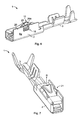
- Fig. 1
- eine schematische, perspektivische Darstellung einer ersten Ausführungsform des erfindungsgemäßen Kontaktelements;
- Fig. 2
- das Kontaktelement aus
Fig. 1 in einer weiteren perspektivischen Darstellung; - Fig. 3
- einen Teil des Kontaktelements aus
Fig. 1 in einer Seitenansicht; - Fig. 4
- einen Teil des Kontaktelements aus
Fig. 1 in einer schematischen Draufsicht; - Fig. 5
- eine schematische Schnittdarstellung des Kontaktelements aus
Fig. 3 entlang einer Schnittlinie F-F; - Fig. 6
- eine weitere Ausführungsform des erfindungsgemäßen Kontaktelementes in einer schematischen, perspektivischen Darstellung;
- Fig. 7
- das Kontaktelement aus
Fig. 6 in einer weiteren perspektivischen Ansicht; - Fig. 8
- einen Teil des Kontaktelements aus
Fig. 6 in einer schematischen Seitenansicht; - Fig. 9
- einen Teil des Kontaktelements aus
Fig. 6 in einer schematischen Draufsicht; - Fig. 10
- eine schematische Darstellung des erfindungsgemäßen Kontaktelements, das in einer Aufnahmevorrichtung angeordnet ist.
- Der Aufbau des erfindungsgemäßen Kontaktelements 1 wird zunächst mit Bezug auf die beispielhafte Ausführungsform der
Fig. 1 bis 5 beschrieben. - Das Kontaktelement 1 umfasst ein Kontaktgehäuse 2 und einen Kontaktkörper 3. Sowohl das Kontaktgehäuse 2 als auch der Kontaktkörper 3 sind aus einem elektrisch leitenden Metallblech hergestellt.
- Bei der Ausführungsform in
Fig. 1 umfasst der Kontaktkörper 3 an einem Ende den Isolationscrimp 4 und den Drahtcrimp 5. Im Bereich der Crimpen 4, 5 bildet der Kontaktkörper 3 eine Art längsverlaufende Rinne oder Mulde. - Der Kontaktkörper 3 kann mit einem Elektrokabel (nicht dargestellt) elektrisch verbunden werden. Dabei wird ein Ende des Elektrokabels (nicht dargestellt) in den mulden- bzw. rinnenförmigen Abschnitt des Kontaktkörpers 3 im Bereich der Crimpen 4, 5 eingelegt. Anschließend wird der Isolationscrimp 4 so umgebogen, dass er das Elektrokabel samt Isolierung einklemmt. Der Drahtcrimp 5 wird umgebogen, wobei das Elektrokabel im Bereich des Drahtcrimps 5 keine Isolierung aufweist. So klemmt der Drahtcrimp 5 den elektrischen Leiter des Elektrokabels ein und der Kontaktkörper 3 ist elektrisch leitend und zugfest mit dem Elektrokabel (nicht dargestellt) verbunden.
- An dem anderen, den Crimpen 4, 5 in Längsrichtung L bzw. Richtung des Elektrokabels gegenüberliegenden Ende des Kontaktkörpers 3 sind wenigstens zwei einander gegenüberliegende Federkontakte 6 ausgebildet. Die Federkontakte 6 bilden eine Aufnahme 6a, in die ein beispielsweise genormtes Steckerelement (nicht dargestellt) zwischen die Federkontakte 6 eingesteckt werden kann.
- Der Kontaktkörper 3 weist ferner wenigstens zwei zwischen den Crimpen 4, 5 und den Federkontakten 6 ausgebildete rechteckige Auskerbungen 7 auf, in die das Kontaktgehäuse 2 eingreift.
- Das Kontaktgehäuse, das auch als Überfeder bezeichnet wird, erstreckt sich im Bereich der Federkontakte 6 um den Kontaktkörper 3 und die Aufnahme 6a. Es weist vier rechtwinklig zueinander angeordnete Seitenwände 8 auf und ist in einer Längsrichtung L des Kontaktelements 1 offen ausgebildet. An den Seitenwänden 8b und 8d sind jeweils rechtwinklig nach innen gebogene Haltezungen 9 ausgebildet, die in den Auskerbungen 7 des Kontaktkörpers eingreifen. Durch die Haltezungen 9 ist das Kontaktgehäuse 2 in der Längsrichtung L formschlüssig mit dem Kontaktkörper 3 verbunden.
- Eine Rastfeder 10 ist an ihrem einen, ersten Ende 11 mit der Seitenwand 8a verbunden. Bei der beispielhaften Ausführungsform in
Fig. 1 ist die Rastfeder 10 einstückig mit der Seitenwand 8a ausgebildet. Die Rastfeder ist als ausgestanzte Zunge ausgebildet, die von der Aufnahme 6a weg nach außen gebogen ist. An ihrem zweiten, freien Ende 12, dem ersten Ende 11 in Längsrichtung 11 gegenüberliegend, weist die Rastfeder 10 eine Abstützfläche 13 auf. Im Bereich des zweiten Endes 12 weist die Oberfläche der Rastfeder 10 eine nach oben erhabene Versteifungssicke 14 auf. Die Versteifungssicke 14 ist in der Draufsicht, sich in Richtung des ersten Endes 11 verjüngend, beispielsweise dreieckig oder keilförmig, ausgebildet. - Da das zweite Ende 12 der Rastfeder 10 frei ausgebildet und das erste Ende 11 mit der Seitenwand 8a elastisch federnd verbunden ist, ist die Rastfeder 10 um eine Schwenkachse 15 schwenkbar. Dadurch ist die Abstützfläche 13 in einer Rastrichtung R beweglich ausgebildet. Die Rastrichtung R verläuft im Wesentlichen quer zur Längsrichtung L.
- Die Rastfeder 10 weist weiterhin einen Haltevorsprung 16 auf, der seitlich, d.h. quer zur Längsrichtung L und quer zur Rastrichtung R, von der Rastfeder 10 absteht. Der Haltevorsprung 16 ist in der Projektion in der Rastrichtung R, die der Ansicht in
Fig. 4 entspricht, im Wesentlichen rechteckig ausgebildet. Eine äußere Kante 17 des Haltevorsprungs 16 verläuft in der Längsrichtung L und fluchtet in der AnsichtFig. 4 mit der Seitenfläche 8b. - Die Seitenwand 8b verläuft in der Längsrichtung L und ragt in der Rastrichtung R, in Richtung nach außen, über die Seitenwand 8a hinaus. In der Rastrichtung R endet die Seitenwand 8b etwa auf Höhe der Abstützfläche 13. Die Seitenwand 8b weist eine Öffnung 18 auf, in die der Haltevorsprung 16 der Rastfeder 10 hineinragt.
- Bei der beispielhaften Ausführungsform in
Fig. 1 weist die Seitenwand 8b eine Biegung 19 auf. Oberhalb dieser Biegung 19 ist die Seitenwand 8b in Richtung der Rastfeder 10 gebogen. Ein oberer Abschnitt 20 der Seitenwand 8b, der oberhalb der Biegung 19 ausgebildet ist, ist zur Mittellinie M der Rastfeder 10 geneigt verlaufend ausgebildet. Ein bügelförmiger Sicherungsabschnitt 20a überlappt den Haltevorsprung 16 in Rastrichtung R. - Die miteinander in Eingriff befindliche Öffnung 18 und Haltevorsprung 16 bilden eine Ausknickschutzanordnung 21 des Kontaktelements 1, die ein Einknicken der Rastfeder 10 im Bereich zwischen den Enden 11, 12 aufgrund einer auf die Abstützfläche 13 wirkenden Kraft verhindert, wie im Anschluss mit Bezug auf die
Fig. 10 genauer erläutert wird. In einer inFig. 1 dargestellten Rastposition liegt der Haltevorsprung 16 an einem oberen Ende 22 der Öffnung 18 an. Das obere Ende 22, das gleichzeitig die Unterkante des Sicherungsabschnittes bildet, verläuft schräg zur Längsrichtung L, etwa im gleichen Winkel wie die Rastfeder 10 in der Rastposition, so dass der Haltevorsprung 16 flächig am oberen Ende 22 anliegt. Da das obere Ende 22 in Richtung der Mittellinie M der Rastfeder 10 gebogen ist, kann ein Einknicken der Rastfeder 10 besonders gut verhindert werden. -
Fig. 6 zeigt eine weitere beispielhafte Ausführungsform des erfindungsgemäßen Kontaktelements 1. Der Kürze halber wird nur auf die Unterschiede zu der Ausführungsform derFig. 1 bis 5 eingegangen, wobei für Elemente, die hinsichtlich Aufbau und/oder Funktion übereinstimmen, dieselben Bezugszeichen verwendet werden. - Im Gegensatz zu der Ausführungsform der
Fig. 1 bis 5 weist die Seitenwand 8a keine Biegung auf, sondern verläuft im Wesentlichen eben bis zum oberen Abschnitt 20. Lediglich oberhalb der Öffnung 18 weist das Kontaktgehäuse 2 der Ausführungsform inFig. 6 eine im Wesentlichen sickenförmige Profilierung 23 oberhalb der Rasteder auf, die den zur Rastfeder hin verlaufenden Sicherungsabschnitt 20a bildet. Die Profilierung 23 verformt die Seitenwand 8a in Richtung der Mittellinie M der Rastfeder 10. Anstatt einer sickenförmigen Ausformung kann die Profilierung 23 auch eine andere Form aufweisen, solange die das Kontaktgehäuse oberhalb der Öffnung 18 in Richtung der Mittellinie M der Rastfeder 10 verformt. So kann die Profilierung 23 beispielsweise auch rechteckig oder dreieckig gebogen sein. -
Fig. 10 zeigt eine Aufnahmevorrichtung 24, in die das erfindungsgemäße Kontaktelement 1 eingesteckt ist. Die Aufnahmevorrichtung 24 hat auf der linken Seite inFig. 10 eine Kontaktöffnung 25, durch die ein Kontaktstecker (nicht dargestellt) zwischen die Federkontakte 6 des Kontaktelements 1 eingesteckt werden kann. Gegenüberliegend zur Kontaktöffnung 25 weist die Aufnahmevorrichtung 24 weiterhin eine Einstecköffnung 26 auf, durch die das Kontaktelement 1 eingesteckt und ein mit dem Kontaktelement 1 verbundenes Kabel (nicht dargestellt) aus der Aufnahmevorrichtung 24 hinausgeführt werden kann. Das Kontaktelement 1 wird in einer Einsteckrichtung E in die Aufnahmevorrichtung eingesteckt. - In der in
Fig. 10 dargestellten Position befindet sich die Rastfeder 10 in ihrer Rastposition, in der sich die Abstützfläche 13 an einer entsprechend ausgebildeten Gegenfläche 27 gegen die Einsteckrichtung E abstützt. Wenn eine Zugkraft Z auf das Kontaktelement 1 einwirkt, stützt sich die Abstützfläche 13 an der Gegenfläche 27 der Aufnahmevorrichtung 24 ab und verhindert ein Herausziehen des Kontaktelements 1 aus der Aufnahmevorrichtung 24. Durch die erfindungsgemäße Ausknickschutzanordnung 21 wird verhindert, dass durch die einwirkende Zugkraft Z die Rastfeder 10 einknickt. So wird eine ungewollte Positionsveränderung des Kontaktelements 1 relativ zur Aufnahmevorrichtung 24 verhindert. - Der in
Fig. 10 der Einfachheit halber nicht dargestellte obere Abschnitt 20 der Seitenwand 8b des Kontaktgehäuses 2 bildet eine Profilierungsfahne der Aufnahmevorrichtung 24 aus. Durch die Profilierungsfahne kann das Kontaktelement 1 nur in einer vorbestimmten Orientierung in die Aufnahmevorrichtung 24 eingeschoben werden, um sicherzustellen, dass die Rastfeder 10 in jedem Fall mit der Gegenfläche 24 verrastet.
Claims (5)
- Kontaktelement (1) zum Verbinden zweier elektrischer Leiter und zum Anordnen in einer Aufnahmevorrichtung (24), mit einem Kontaktgehäuse (2) und mit einer am Kontaktgehäuse (2) gehaltenen, in einer Längsrichtung (L) des Kontaktgehäuses (2) verlaufenden Rastfeder (10), deren freies Ende (12) in einer quer zur Längsrichtung (L) verlaufenden Rastrichtung (R) beweglich ist und die einen in eine Öffnung (18) des Kontaktgehäuses (2) ragenden Haltevorsprung (16) aufweist, wobei das Kontaktelement (1) durch die Rastfeder (10) in der Aufnahmevorrichtung (24) verrastbar ausgebildet ist und ein Sicherungsabschnitt (20a) des Kontaktgehäuses (2) den Haltevorsprung (16) in einer Projektion in der Rastrichtung (R) wenigstens abschnittsweise überlappt, dadurch gekennzeichnet, dass der Sicherungsabschnitt (20a) wenigstens abschnittsweise zur Rastfeder (10) hin verläuft.
- Kontaktelement (1) nach Anspruch 1, dadurch gekennzeichnet, dass der Sicherungsabschnitt (20a) wenigstens abschnittsweise in Richtung der Rastfeder (10) gebogen ist.
- Kontaktelement (1) nach Anspruch 1 oder 2, dadurch gekennzeichnet, dass das Kontaktgehäuse (2) wenigstens eine in der Längsrichtung (L) verlaufende Biegung (19) aufweist, ab der das Kontaktgehäuse (2) in Richtung der Rastfeder (10) gebogen ist.
- Kontaktelement nach einem der oben genannten Ansprüche, dadurch gekennzeichnet, dass das Kontaktgehäuse (2) wenigstens eine in Richtung der Rastfeder (10) verlaufende Profilierung (23) aufweist.
- Kontaktelement nach Anspruch 4, dadurch gekennzeichnet, dass die Profilierung (23) bogenförmig ausgestaltet ist.
Applications Claiming Priority (1)
| Application Number | Priority Date | Filing Date | Title |
|---|---|---|---|
| DE200710008941 DE102007008941B3 (de) | 2007-02-21 | 2007-02-21 | Kontaktelement |
Publications (3)
| Publication Number | Publication Date |
|---|---|
| EP1962386A2 true EP1962386A2 (de) | 2008-08-27 |
| EP1962386A3 EP1962386A3 (de) | 2011-08-10 |
| EP1962386B1 EP1962386B1 (de) | 2013-08-28 |
Family
ID=39432976
Family Applications (1)
| Application Number | Title | Priority Date | Filing Date |
|---|---|---|---|
| EP20080002940 Active EP1962386B1 (de) | 2007-02-21 | 2008-02-18 | Kontaktelement |
Country Status (2)
| Country | Link |
|---|---|
| EP (1) | EP1962386B1 (de) |
| DE (1) | DE102007008941B3 (de) |
Cited By (5)
| Publication number | Priority date | Publication date | Assignee | Title |
|---|---|---|---|---|
| WO2013091935A1 (de) * | 2011-12-20 | 2013-06-27 | Robert Bosch Gmbh | Elektrisches kontaktelement mit rastlanze für ein steckergehäuse |
| WO2013156216A1 (de) * | 2012-04-17 | 2013-10-24 | Robert Bosch Gmbh | Steckverbindungskontakt mit nach aussen überstehender primärlanze |
| JP2014078507A (ja) * | 2012-10-05 | 2014-05-01 | Robert Bosch Gmbh | 差し込み式接続エレメントのコンタクトチャンバ内に係止されるコンタクト並びに差し込み式接続エレメント |
| EP2740185B1 (de) * | 2011-08-03 | 2018-03-21 | Robert Bosch GmbH | Elektrisches kontaktelement mit rastlanze für ein steckergehäuse |
| CN111525326A (zh) * | 2019-02-01 | 2020-08-11 | 科迈士瑞士股份有限公司 | 用于抓持和操纵线缆端部的抓具单元、具有抓具单元的配置站以及用于配置插头壳体的方法 |
Families Citing this family (1)
| Publication number | Priority date | Publication date | Assignee | Title |
|---|---|---|---|---|
| CN117317640B (zh) * | 2022-06-24 | 2025-07-11 | 比亚迪股份有限公司 | 端子、电连接器、线束和车辆 |
Citations (1)
| Publication number | Priority date | Publication date | Assignee | Title |
|---|---|---|---|---|
| EP1420482A2 (de) | 2002-11-15 | 2004-05-19 | Tyco Electronics AMP GmbH | Kontaktelement mit Federzunge |
Family Cites Families (5)
| Publication number | Priority date | Publication date | Assignee | Title |
|---|---|---|---|---|
| GB8531935D0 (en) * | 1985-12-31 | 1986-02-05 | Amp Gmbh | Electrical socket terminal & connector |
| FR2741204A1 (fr) * | 1995-11-14 | 1997-05-16 | Amp France | Assemblage de connecteur electrique |
| JPH10162891A (ja) * | 1996-11-28 | 1998-06-19 | Sumitomo Wiring Syst Ltd | 端子金具 |
| JP3575583B2 (ja) * | 1997-03-25 | 2004-10-13 | 矢崎総業株式会社 | 端子 |
| EP1239547B1 (de) * | 2001-03-06 | 2006-06-07 | Tyco Electronics AMP GmbH | Elektrischer Kontakt, insbesonder Kontaktstift |
-
2007
- 2007-02-21 DE DE200710008941 patent/DE102007008941B3/de not_active Expired - Fee Related
-
2008
- 2008-02-18 EP EP20080002940 patent/EP1962386B1/de active Active
Patent Citations (1)
| Publication number | Priority date | Publication date | Assignee | Title |
|---|---|---|---|---|
| EP1420482A2 (de) | 2002-11-15 | 2004-05-19 | Tyco Electronics AMP GmbH | Kontaktelement mit Federzunge |
Cited By (6)
| Publication number | Priority date | Publication date | Assignee | Title |
|---|---|---|---|---|
| EP2740185B1 (de) * | 2011-08-03 | 2018-03-21 | Robert Bosch GmbH | Elektrisches kontaktelement mit rastlanze für ein steckergehäuse |
| WO2013091935A1 (de) * | 2011-12-20 | 2013-06-27 | Robert Bosch Gmbh | Elektrisches kontaktelement mit rastlanze für ein steckergehäuse |
| WO2013156216A1 (de) * | 2012-04-17 | 2013-10-24 | Robert Bosch Gmbh | Steckverbindungskontakt mit nach aussen überstehender primärlanze |
| US9666969B2 (en) | 2012-04-17 | 2017-05-30 | Robert Bosch Gmbh | Connector assembly contact having an outwardly projecting primary lance |
| JP2014078507A (ja) * | 2012-10-05 | 2014-05-01 | Robert Bosch Gmbh | 差し込み式接続エレメントのコンタクトチャンバ内に係止されるコンタクト並びに差し込み式接続エレメント |
| CN111525326A (zh) * | 2019-02-01 | 2020-08-11 | 科迈士瑞士股份有限公司 | 用于抓持和操纵线缆端部的抓具单元、具有抓具单元的配置站以及用于配置插头壳体的方法 |
Also Published As
| Publication number | Publication date |
|---|---|
| EP1962386B1 (de) | 2013-08-28 |
| EP1962386A3 (de) | 2011-08-10 |
| DE102007008941B3 (de) | 2008-08-28 |
Similar Documents
| Publication | Publication Date | Title |
|---|---|---|
| EP2956993B1 (de) | Federklemmkontakt und verbindungsklemme für elektrische leiter | |
| EP3324490B1 (de) | Federklemmkontakt zur kontaktierung elektrischer leiter, leiteranschlussklemme und verfahren zur herstellung eines federklemmkontakts | |
| EP2843764B1 (de) | Federkraftklemme für Leiter | |
| EP0859431B1 (de) | Einstückige Kontaktfeder | |
| EP3118938B1 (de) | Steckverbinder | |
| WO2015128407A1 (de) | Verbindungsklemme und federkraftklemmkontakt hierzu | |
| DE102006049563B3 (de) | Steckverbinder mit verbesserter Kabelzugentlastung | |
| DE69403428T2 (de) | Elektrischer Verbinder und Anschlusselement dafür zur Verbindung mit ein Messerkontakt | |
| DE202013105944U1 (de) | Federkraft-Klemmanschluss und Steckverbinder hiermit | |
| DE102018117508B4 (de) | Leiteranschlussklemme | |
| EP1962386B1 (de) | Kontaktelement | |
| EP3586404B1 (de) | Federkraftanschluss und rundsteckverbinder mit einer vielzahl von federkraftanschlüssen | |
| EP1816711B1 (de) | Verfahren zur Herstellung einer Verrastungsvorrichtung für einen elektrischen Kontakt in einem Steckverbinder | |
| WO2020259926A1 (de) | Elektrische anschlussklemme | |
| DE102006030784B4 (de) | Steckverbinder mit einer Sekundärverriegelung | |
| EP3849019B1 (de) | Leiteranschlussklemme | |
| DE102016102036B4 (de) | Elektrischer Steckkontakt, elektrische Anschlussklemme und Verfahren zur Herstellung eines elektrischen Steckkontakts | |
| DE20305313U1 (de) | Anschlußeinrichtung | |
| EP3698439B1 (de) | Steckverbinderteil | |
| EP3136519B1 (de) | Anschlusseinrichtung zum anschluss eines leiters an einer sammelschiene | |
| DE102012218234B4 (de) | Verrastbarer Kontakt mit von Seitenwand übergriffener Primärverriegelungslanze | |
| DE3030523A1 (de) | Elektrische anschlussklemme | |
| DE102016105192B3 (de) | Leiteranschlussklemme | |
| DE29506206U1 (de) | Kontaktfeder | |
| DE10320460A1 (de) | Elektrische Steckverbindung |
Legal Events
| Date | Code | Title | Description |
|---|---|---|---|
| PUAI | Public reference made under article 153(3) epc to a published international application that has entered the european phase |
Free format text: ORIGINAL CODE: 0009012 |
|
| AK | Designated contracting states |
Kind code of ref document: A2 Designated state(s): AT BE BG CH CY CZ DE DK EE ES FI FR GB GR HR HU IE IS IT LI LT LU LV MC MT NL NO PL PT RO SE SI SK TR |
|
| AX | Request for extension of the european patent |
Extension state: AL BA MK RS |
|
| PUAL | Search report despatched |
Free format text: ORIGINAL CODE: 0009013 |
|
| AK | Designated contracting states |
Kind code of ref document: A3 Designated state(s): AT BE BG CH CY CZ DE DK EE ES FI FR GB GR HR HU IE IS IT LI LT LU LV MC MT NL NO PL PT RO SE SI SK TR |
|
| AX | Request for extension of the european patent |
Extension state: AL BA MK RS |
|
| RIC1 | Information provided on ipc code assigned before grant |
Ipc: H01R 13/432 20060101AFI20110704BHEP |
|
| 17P | Request for examination filed |
Effective date: 20120109 |
|
| AKX | Designation fees paid |
Designated state(s): AT BE BG CH CY CZ DE DK EE ES FI FR GB GR HR HU IE IS IT LI LT LU LV MC MT NL NO PL PT RO SE SI SK TR |
|
| GRAP | Despatch of communication of intention to grant a patent |
Free format text: ORIGINAL CODE: EPIDOSNIGR1 |
|
| INTG | Intention to grant announced |
Effective date: 20130408 |
|
| GRAS | Grant fee paid |
Free format text: ORIGINAL CODE: EPIDOSNIGR3 |
|
| GRAA | (expected) grant |
Free format text: ORIGINAL CODE: 0009210 |
|
| AK | Designated contracting states |
Kind code of ref document: B1 Designated state(s): AT BE BG CH CY CZ DE DK EE ES FI FR GB GR HR HU IE IS IT LI LT LU LV MC MT NL NO PL PT RO SE SI SK TR |
|
| REG | Reference to a national code |
Ref country code: GB Ref legal event code: FG4D Free format text: NOT ENGLISH |
|
| REG | Reference to a national code |
Ref country code: CH Ref legal event code: EP |
|
| REG | Reference to a national code |
Ref country code: AT Ref legal event code: REF Ref document number: 629781 Country of ref document: AT Kind code of ref document: T Effective date: 20130915 |
|
| REG | Reference to a national code |
Ref country code: IE Ref legal event code: FG4D Free format text: LANGUAGE OF EP DOCUMENT: GERMAN |
|
| REG | Reference to a national code |
Ref country code: DE Ref legal event code: R096 Ref document number: 502008010550 Country of ref document: DE Effective date: 20131024 |
|
| REG | Reference to a national code |
Ref country code: CH Ref legal event code: NV Representative=s name: MARKS AND CLERK (LUXEMBOURG) LLP, CH |
|
| REG | Reference to a national code |
Ref country code: LT Ref legal event code: MG4D |
|
| REG | Reference to a national code |
Ref country code: NL Ref legal event code: VDEP Effective date: 20130828 |
|
| PG25 | Lapsed in a contracting state [announced via postgrant information from national office to epo] |
Ref country code: HR Free format text: LAPSE BECAUSE OF FAILURE TO SUBMIT A TRANSLATION OF THE DESCRIPTION OR TO PAY THE FEE WITHIN THE PRESCRIBED TIME-LIMIT Effective date: 20130828 Ref country code: IS Free format text: LAPSE BECAUSE OF FAILURE TO SUBMIT A TRANSLATION OF THE DESCRIPTION OR TO PAY THE FEE WITHIN THE PRESCRIBED TIME-LIMIT Effective date: 20131228 Ref country code: NO Free format text: LAPSE BECAUSE OF FAILURE TO SUBMIT A TRANSLATION OF THE DESCRIPTION OR TO PAY THE FEE WITHIN THE PRESCRIBED TIME-LIMIT Effective date: 20131128 Ref country code: PT Free format text: LAPSE BECAUSE OF FAILURE TO SUBMIT A TRANSLATION OF THE DESCRIPTION OR TO PAY THE FEE WITHIN THE PRESCRIBED TIME-LIMIT Effective date: 20131230 Ref country code: CY Free format text: LAPSE BECAUSE OF FAILURE TO SUBMIT A TRANSLATION OF THE DESCRIPTION OR TO PAY THE FEE WITHIN THE PRESCRIBED TIME-LIMIT Effective date: 20130626 Ref country code: LT Free format text: LAPSE BECAUSE OF FAILURE TO SUBMIT A TRANSLATION OF THE DESCRIPTION OR TO PAY THE FEE WITHIN THE PRESCRIBED TIME-LIMIT Effective date: 20130828 Ref country code: SE Free format text: LAPSE BECAUSE OF FAILURE TO SUBMIT A TRANSLATION OF THE DESCRIPTION OR TO PAY THE FEE WITHIN THE PRESCRIBED TIME-LIMIT Effective date: 20130828 |
|
| REG | Reference to a national code |
Ref country code: NL Ref legal event code: VDEP Effective date: 20130828 |
|
| PG25 | Lapsed in a contracting state [announced via postgrant information from national office to epo] |
Ref country code: PL Free format text: LAPSE BECAUSE OF FAILURE TO SUBMIT A TRANSLATION OF THE DESCRIPTION OR TO PAY THE FEE WITHIN THE PRESCRIBED TIME-LIMIT Effective date: 20130828 Ref country code: SI Free format text: LAPSE BECAUSE OF FAILURE TO SUBMIT A TRANSLATION OF THE DESCRIPTION OR TO PAY THE FEE WITHIN THE PRESCRIBED TIME-LIMIT Effective date: 20130828 Ref country code: GR Free format text: LAPSE BECAUSE OF FAILURE TO SUBMIT A TRANSLATION OF THE DESCRIPTION OR TO PAY THE FEE WITHIN THE PRESCRIBED TIME-LIMIT Effective date: 20131129 Ref country code: LV Free format text: LAPSE BECAUSE OF FAILURE TO SUBMIT A TRANSLATION OF THE DESCRIPTION OR TO PAY THE FEE WITHIN THE PRESCRIBED TIME-LIMIT Effective date: 20130828 Ref country code: FI Free format text: LAPSE BECAUSE OF FAILURE TO SUBMIT A TRANSLATION OF THE DESCRIPTION OR TO PAY THE FEE WITHIN THE PRESCRIBED TIME-LIMIT Effective date: 20130828 |
|
| REG | Reference to a national code |
Ref country code: SK Ref legal event code: T3 Ref document number: E 15286 Country of ref document: SK |
|
| PG25 | Lapsed in a contracting state [announced via postgrant information from national office to epo] |
Ref country code: CY Free format text: LAPSE BECAUSE OF FAILURE TO SUBMIT A TRANSLATION OF THE DESCRIPTION OR TO PAY THE FEE WITHIN THE PRESCRIBED TIME-LIMIT Effective date: 20130828 |
|
| PG25 | Lapsed in a contracting state [announced via postgrant information from national office to epo] |
Ref country code: DK Free format text: LAPSE BECAUSE OF FAILURE TO SUBMIT A TRANSLATION OF THE DESCRIPTION OR TO PAY THE FEE WITHIN THE PRESCRIBED TIME-LIMIT Effective date: 20130828 Ref country code: EE Free format text: LAPSE BECAUSE OF FAILURE TO SUBMIT A TRANSLATION OF THE DESCRIPTION OR TO PAY THE FEE WITHIN THE PRESCRIBED TIME-LIMIT Effective date: 20130828 Ref country code: CZ Free format text: LAPSE BECAUSE OF FAILURE TO SUBMIT A TRANSLATION OF THE DESCRIPTION OR TO PAY THE FEE WITHIN THE PRESCRIBED TIME-LIMIT Effective date: 20130828 Ref country code: NL Free format text: LAPSE BECAUSE OF FAILURE TO SUBMIT A TRANSLATION OF THE DESCRIPTION OR TO PAY THE FEE WITHIN THE PRESCRIBED TIME-LIMIT Effective date: 20130828 Ref country code: RO Free format text: LAPSE BECAUSE OF FAILURE TO SUBMIT A TRANSLATION OF THE DESCRIPTION OR TO PAY THE FEE WITHIN THE PRESCRIBED TIME-LIMIT Effective date: 20130828 |
|
| PG25 | Lapsed in a contracting state [announced via postgrant information from national office to epo] |
Ref country code: ES Free format text: LAPSE BECAUSE OF FAILURE TO SUBMIT A TRANSLATION OF THE DESCRIPTION OR TO PAY THE FEE WITHIN THE PRESCRIBED TIME-LIMIT Effective date: 20130828 |
|
| REG | Reference to a national code |
Ref country code: DE Ref legal event code: R097 Ref document number: 502008010550 Country of ref document: DE |
|
| PLBE | No opposition filed within time limit |
Free format text: ORIGINAL CODE: 0009261 |
|
| STAA | Information on the status of an ep patent application or granted ep patent |
Free format text: STATUS: NO OPPOSITION FILED WITHIN TIME LIMIT |
|
| 26N | No opposition filed |
Effective date: 20140530 |
|
| BERE | Be: lapsed |
Owner name: TYCO ELECTRONICS AMP G.M.B.H. Effective date: 20140228 |
|
| REG | Reference to a national code |
Ref country code: DE Ref legal event code: R097 Ref document number: 502008010550 Country of ref document: DE Effective date: 20140530 |
|
| PG25 | Lapsed in a contracting state [announced via postgrant information from national office to epo] |
Ref country code: MC Free format text: LAPSE BECAUSE OF FAILURE TO SUBMIT A TRANSLATION OF THE DESCRIPTION OR TO PAY THE FEE WITHIN THE PRESCRIBED TIME-LIMIT Effective date: 20130828 Ref country code: LU Free format text: LAPSE BECAUSE OF FAILURE TO SUBMIT A TRANSLATION OF THE DESCRIPTION OR TO PAY THE FEE WITHIN THE PRESCRIBED TIME-LIMIT Effective date: 20140218 |
|
| REG | Reference to a national code |
Ref country code: IE Ref legal event code: MM4A |
|
| PG25 | Lapsed in a contracting state [announced via postgrant information from national office to epo] |
Ref country code: IE Free format text: LAPSE BECAUSE OF NON-PAYMENT OF DUE FEES Effective date: 20140218 Ref country code: BE Free format text: LAPSE BECAUSE OF NON-PAYMENT OF DUE FEES Effective date: 20140228 |
|
| REG | Reference to a national code |
Ref country code: FR Ref legal event code: PLFP Year of fee payment: 8 |
|
| REG | Reference to a national code |
Ref country code: AT Ref legal event code: MM01 Ref document number: 629781 Country of ref document: AT Kind code of ref document: T Effective date: 20140218 |
|
| PG25 | Lapsed in a contracting state [announced via postgrant information from national office to epo] |
Ref country code: AT Free format text: LAPSE BECAUSE OF NON-PAYMENT OF DUE FEES Effective date: 20140218 |
|
| REG | Reference to a national code |
Ref country code: DE Ref legal event code: R082 Ref document number: 502008010550 Country of ref document: DE Representative=s name: GRUENECKER PATENT- UND RECHTSANWAELTE PARTG MB, DE Ref country code: DE Ref legal event code: R081 Ref document number: 502008010550 Country of ref document: DE Owner name: TE CONNECTIVITY GERMANY GMBH, DE Free format text: FORMER OWNER: TYCO ELECTRONICS AMP GMBH, 64625 BENSHEIM, DE |
|
| REG | Reference to a national code |
Ref country code: FR Ref legal event code: CD Owner name: TE CONNECTIVITY GERMANY GMBH Effective date: 20151027 |
|
| REG | Reference to a national code |
Ref country code: FR Ref legal event code: PLFP Year of fee payment: 9 |
|
| PG25 | Lapsed in a contracting state [announced via postgrant information from national office to epo] |
Ref country code: MT Free format text: LAPSE BECAUSE OF FAILURE TO SUBMIT A TRANSLATION OF THE DESCRIPTION OR TO PAY THE FEE WITHIN THE PRESCRIBED TIME-LIMIT Effective date: 20130828 |
|
| REG | Reference to a national code |
Ref country code: CH Ref legal event code: PFA Owner name: TE CONNECTIVITY GERMANY GMBH, DE Free format text: FORMER OWNER: TYCO ELECTRONICS AMP GMBH, DE |
|
| PG25 | Lapsed in a contracting state [announced via postgrant information from national office to epo] |
Ref country code: BG Free format text: LAPSE BECAUSE OF FAILURE TO SUBMIT A TRANSLATION OF THE DESCRIPTION OR TO PAY THE FEE WITHIN THE PRESCRIBED TIME-LIMIT Effective date: 20130828 |
|
| REG | Reference to a national code |
Ref country code: SK Ref legal event code: TC4A Ref document number: E 15286 Country of ref document: SK Owner name: TE CONNECTIVITY GERMANY GMBH, BENSHEIM, DE Effective date: 20160511 |
|
| PG25 | Lapsed in a contracting state [announced via postgrant information from national office to epo] |
Ref country code: TR Free format text: LAPSE BECAUSE OF FAILURE TO SUBMIT A TRANSLATION OF THE DESCRIPTION OR TO PAY THE FEE WITHIN THE PRESCRIBED TIME-LIMIT Effective date: 20130828 Ref country code: HU Free format text: LAPSE BECAUSE OF FAILURE TO SUBMIT A TRANSLATION OF THE DESCRIPTION OR TO PAY THE FEE WITHIN THE PRESCRIBED TIME-LIMIT; INVALID AB INITIO Effective date: 20080218 |
|
| REG | Reference to a national code |
Ref country code: FR Ref legal event code: PLFP Year of fee payment: 10 |
|
| REG | Reference to a national code |
Ref country code: FR Ref legal event code: PLFP Year of fee payment: 11 |
|
| PGFP | Annual fee paid to national office [announced via postgrant information from national office to epo] |
Ref country code: PL Payment date: 20190220 Year of fee payment: 14 Ref country code: CH Payment date: 20190215 Year of fee payment: 12 Ref country code: IT Payment date: 20190221 Year of fee payment: 12 Ref country code: FR Payment date: 20190111 Year of fee payment: 12 |
|
| PGFP | Annual fee paid to national office [announced via postgrant information from national office to epo] |
Ref country code: SK Payment date: 20190114 Year of fee payment: 12 |
|
| REG | Reference to a national code |
Ref country code: CH Ref legal event code: PL |
|
| GBPC | Gb: european patent ceased through non-payment of renewal fee |
Effective date: 20200218 |
|
| PG25 | Lapsed in a contracting state [announced via postgrant information from national office to epo] |
Ref country code: SK Free format text: LAPSE BECAUSE OF NON-PAYMENT OF DUE FEES Effective date: 20200218 |
|
| REG | Reference to a national code |
Ref country code: SK Ref legal event code: MM4A Ref document number: E 15286 Country of ref document: SK Effective date: 20200218 |
|
| PG25 | Lapsed in a contracting state [announced via postgrant information from national office to epo] |
Ref country code: CH Free format text: LAPSE BECAUSE OF NON-PAYMENT OF DUE FEES Effective date: 20200229 Ref country code: LI Free format text: LAPSE BECAUSE OF NON-PAYMENT OF DUE FEES Effective date: 20200229 |
|
| PG25 | Lapsed in a contracting state [announced via postgrant information from national office to epo] |
Ref country code: FR Free format text: LAPSE BECAUSE OF NON-PAYMENT OF DUE FEES Effective date: 20200229 Ref country code: GB Free format text: LAPSE BECAUSE OF NON-PAYMENT OF DUE FEES Effective date: 20200218 |
|
| PG25 | Lapsed in a contracting state [announced via postgrant information from national office to epo] |
Ref country code: IT Free format text: LAPSE BECAUSE OF NON-PAYMENT OF DUE FEES Effective date: 20200218 |
|
| PGFP | Annual fee paid to national office [announced via postgrant information from national office to epo] |
Ref country code: DE Payment date: 20251224 Year of fee payment: 19 |