EP1962028B1 - Innenraumeinheit für klimaanlage - Google Patents
Innenraumeinheit für klimaanlage Download PDFInfo
- Publication number
- EP1962028B1 EP1962028B1 EP06833006.7A EP06833006A EP1962028B1 EP 1962028 B1 EP1962028 B1 EP 1962028B1 EP 06833006 A EP06833006 A EP 06833006A EP 1962028 B1 EP1962028 B1 EP 1962028B1
- Authority
- EP
- European Patent Office
- Prior art keywords
- opening
- closing
- panel
- indoor unit
- closing mechanism
- Prior art date
- Legal status (The legal status is an assumption and is not a legal conclusion. Google has not performed a legal analysis and makes no representation as to the accuracy of the status listed.)
- Active
Links
- 238000001514 detection method Methods 0.000 claims description 44
- 230000033001 locomotion Effects 0.000 claims description 5
- 238000010276 construction Methods 0.000 description 8
- 238000010586 diagram Methods 0.000 description 2
- 230000015556 catabolic process Effects 0.000 description 1
- 238000006731 degradation reaction Methods 0.000 description 1
- 230000003287 optical effect Effects 0.000 description 1
Images


Classifications
-
- F—MECHANICAL ENGINEERING; LIGHTING; HEATING; WEAPONS; BLASTING
- F24—HEATING; RANGES; VENTILATING
- F24F—AIR-CONDITIONING; AIR-HUMIDIFICATION; VENTILATION; USE OF AIR CURRENTS FOR SCREENING
- F24F1/00—Room units for air-conditioning, e.g. separate or self-contained units or units receiving primary air from a central station
- F24F1/0007—Indoor units, e.g. fan coil units
- F24F1/0043—Indoor units, e.g. fan coil units characterised by mounting arrangements
- F24F1/0057—Indoor units, e.g. fan coil units characterised by mounting arrangements mounted in or on a wall
-
- F—MECHANICAL ENGINEERING; LIGHTING; HEATING; WEAPONS; BLASTING
- F24—HEATING; RANGES; VENTILATING
- F24F—AIR-CONDITIONING; AIR-HUMIDIFICATION; VENTILATION; USE OF AIR CURRENTS FOR SCREENING
- F24F1/00—Room units for air-conditioning, e.g. separate or self-contained units or units receiving primary air from a central station
- F24F1/0007—Indoor units, e.g. fan coil units
- F24F1/0059—Indoor units, e.g. fan coil units characterised by heat exchangers
- F24F1/0067—Indoor units, e.g. fan coil units characterised by heat exchangers by the shape of the heat exchangers or of parts thereof, e.g. of their fins
Definitions
- the present invention relates to an indoor unit for air conditioners.
- an indoor unit for air conditioners including an opening/closing panel for opening and closing an opening of a front panel
- This air-conditioner indoor unit has a bottom frame on which a heat exchanger and a blower fan are mounted, and a front panel which is removably fitted so as to cover the front face side of the bottom frame.
- the air-conditioner indoor unit also includes a driver part placed on the bottom frame side, and an opening/closing mechanism placed on the front panel side, so that the opening/closing panel is moved by the opening/closing mechanism with driving force of the driver part.
- an object of the present invention is to provide an indoor unit for air conditioners which is enabled to detect an opening/closing state of the opening/closing panel with a simple construction without connecting the front panel and the bottom-frame side electrical parts to each other via a junction harness so that assemblability, maintainability and reliability of the indoor unit can be improved.
- an indoor unit for air conditioners according to claim 1.
- an opening/closing mechanism for opening and closing the opening/closing panel is placed on the front panel while the driver part for driving the opening/closing mechanism is placed on the bottom frame, and the opening/closing mechanism is driven by the driver part. Then, the movable part of the opening/closing mechanism driven by the driver part is moved, and based on the motion of the movable part, an opening/closing state of the opening/closing panel is detected by the opening/closing detection part placed on the bottom frame.
- the opening/closing detection part for detecting the opening/closing state of the opening/closing panel is not provided on the front panel side, removal from the bottom frame or opening/closing of the front panel has no influence on electrical connections in electrical parts of the opening/closing detection part, the driver part or the like. That is, since the opening/closing detection part that is an electrical part is not provided on the front panel side, the need for a junction harness is eliminated. Therefore, the opening/closing state of the opening/closing panel can be detected with a simple construction, so that the assemblability, maintainability and reliability can be improved.
- the movable part of the opening/closing mechanism has a drive shaft which rotates with driving force of the driver part, and the opening/closing detection part detects an opening/closing state of the opening/closing panel based on rotation of the drive shaft.
- the opening/closing detection part detects the opening/closing state of the opening/closing panel based on rotation of the shaft of the movable part
- the construction can be simplified by using, for example, a microswitch or the like.
- the movable part of the opening/closing mechanism has a cam which rotates along with rotation of the drive shaft, and the opening/closing detection part detects an opening/closing state of the opening/closing panel based on rotation of the cam of the opening/closing mechanism.
- the opening/closing detection part detects the opening/closing state of the opening/closing panel based on the cam that rotates along with rotation of the shaft of the movable part.
- the opening/closing state of the opening/closing panel can be detected accurately and reliably.
- the opening/closing mechanism includes a first opening/closing mechanism part and a second opening/closing mechanism part which are provided near left-and-right side faces of the front panel, respectively, and which are coupled to each other by the drive shaft, and as either one of the first and second opening/closing mechanism parts is driven by the driver part, the other of the first and second opening/closing mechanism parts is driven via the drive shaft that transmits driving force of the driver part.
- the other of the first and second opening/closing mechanism parts is driven via the shaft that transmits driving force of the driver part.
- the opening/closing panel is opened or closed by the first and second opening/closing mechanism parts on the left and right of the front panel, by which opening/closing driving force is given to both left and right sides of the opening/closing panel, so that the opening/closing panel can be opened or closed smoothly and evenly.
- the opening/closing state of the opening/closing panel can be detected with a simple construction, making it possible to achieve an air-conditioner indoor unit which can be improved in assemblability, maintainability and reliability.
- the opening/closing detection part detects an opening/closing state of the opening/closing panel based on rotation of the shaft of the movable part.
- the construction can be simplified by using, for example, a microswitch or the like.
- the opening/closing detection part detects a opening/closing state of the opening/closing panel based on the cam that rotates along with rotation of the shaft of the movable part.
- the opening/closing state of the opening/closing panel can be detected accurately and reliably.
- either one of the first and second opening/closing mechanism parts placed near the left-and-right side faces of the front panel, respectively, is driven by the driver part, and the other of the first and second opening/closing mechanism parts is driven via the shaft that transmits driving force of the driver part, so that the opening/closing panel is opened or closed by the first and second opening/closing mechanism parts.
- opening/closing driving force is given to both left and right sides of the opening/closing panel, so that the opening/closing panel can be opened or closed smoothly and evenly.
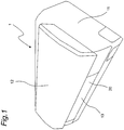
- Fig. 1 shows a perspective view of an air-conditioner indoor unit according to one embodiment of the invention.
- the air-conditioner indoor unit 1 is a wall-mounted type indoor unit to be fitted on a wall surface in a room.
- the air-conditioner indoor unit 1 includes a front panel 11 removably fitted on the front face side of a bottom frame 10 (shown in Fig. 3 ), and an opening/closing panel 12 for opening and closing an intake opening of the front panel 11, while a horizontal flap 13 is placed at a blowoff opening 20 provided on a lower side of the front panel 11.
- Shown in Fig. 1 is an operation halt state in which the intake opening (not shown) on the front face side of the front panel 11 is closed by the opening/closing panel 12 while the blowoff opening 20 is closed by the horizontal flap 13.
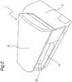
- FIG. 2 shows a perspective view of the air-conditioner indoor unit 1 in an operating state thereof.
- the opening/closing panel 12 slides frontward and diagonally upward and moreover the horizontal flap 13 turns so that the blowoff opening 20 opens. Further, there opens a gap between an upper end side of the opening/closing panel 12 and the front face side of the front panel 11, by which a wind passage to an intake opening 11a (shown in Fig. 4 ) of the front panel 11 is formed.
- Fig. 3 shows a sectional view of the air-conditioner indoor unit 1 with the opening/closing panel 12 in a closed state.
- an indoor heat exchanger 21 having a dogleg-shaped cross section is placed within a body casing composed of the bottom frame 10 and the front panel 11 fitted on the front face side of the bottom frame 10, while a blower fan 22 is placed on the lower side of the indoor heat exchanger 21.
- the blower fan 22 is a cross flow fan which is positioned with its rotating shaft aligned horizontal.
- Fig. 4 shows a sectional view of the air-conditioner indoor unit 1 with the opening/closing panel 12 in an open state.
- the opening/closing panel 12 moves frontward and diagonally upward, while the horizontal flap 13 turns with the blowoff opening 20 opened.
- the blower fan 22 is driven by a fan motor (not shown)
- indoor air is sucked in through the intake opening 11a from between the upper end side of the opening/closing panel 12 and the front face side of the front panel 11, while the air is sucked in from indoors via an intake opening (not shown) on the upper side of the front panel 11.
- the sucked indoor air is passed through the indoor heat exchanger 21, where heat exchanged therewith, and thereafter passed through a blowoff passage 23 by the blower fan 22 so as to be blown out from the blowoff opening 20 into the room.
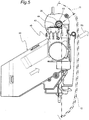
- Fig. 5 shows a side view of a first opening/closing mechanism part 30 and a driver part 40 of the air-conditioner indoor unit 1.
- the first opening/closing mechanism part 30 for opening and closing the opening/closing panel 12 is placed inside and near the right side face of the front panel 11 as viewed from the front.
- Fig. 5 is a side view of the front panel 11 in its central to right-side part.
- a second opening/closing mechanism part (not shown) which is generally left-right symmetrical to the first opening/closing mechanism part 30 is mounted inside and near the left side face of the front panel 11 as viewed from the front.
- the first opening/closing mechanism part 30 and the second opening/closing mechanism part are coupled with each other via a drive shaft 36.
- driving force of the driver part 40 is transmitted via the drive shaft 36, so that the second opening/closing mechanism part is driven.
- the first opening/closing mechanism part 30 and the second opening/closing mechanism part constitute an opening/closing mechanism.
- Fig. 6 shows a side view of the first opening/closing mechanism part 30.
- the first opening/closing mechanism part 30 has an opening/closing mechanism casing 31, a panel support member 32 which is slidably housed in the opening/closing mechanism casing 31 and which supports the opening/closing panel 12 (shown in Figs. 1 to 4 ) by the front face side, a gear case part 33 provided on the upper side of the opening/closing mechanism casing 31, a second gear 34 placed within the gear case part 33, and a third gear 35 to be engaged with the second gear 34.
- the drive shaft 36 is used as a rotating shaft for the second gear 34.
- the third gear 35 is engaged with a rack (not shown) provided on the panel support member 32, and the panel support member 32 is slid by the second gear 34 and the third gear 35 being driven by the driver part 40.
- the direction of this slide of the panel support member 32 is a direction in which the opening/closing panel 12 moves frontward and diagonally upward (a direction of arrow R1 shown in Fig. 5 ).
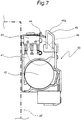
- Fig. 7 shows a side view of the driver part 40, and this driver part 40 is fitted to a support member 47 fixed to the bottom frame 10 (shown in Fig. 3 ).
- the driver part 40 has a driver part casing 41, a panel driving motor 42 fitted to the driver part casing 41, a detection switch 43 as an example of an opening/closing detection part mounted on the upper side of the driver part casing 41, and a first gear 46 to be driven by the panel driving motor 42.
- the first gear 46 of the driver part 40 and the second gear 34 of the first opening/closing mechanism part 30 are engaged with each other, so that driving force of the panel driving motor 42 is transmitted to the first opening/closing mechanism part 30 and the second opening/closing mechanism part.
- the detection switch 43 is provided by using a microswitch, having a lever 44 which is movable by a hinge mechanism.
- a guide part 45 is provided on the upper side of the driver part casing 41.
- This guide part 45 serves to guide a cam 50 fixed to the drive shaft 36 shown in Fig. 5 when the front panel 11 is fitted to the bottom frame 10 shown in Fig. 3 . That is, the cam 50 fixed to the drive shaft 36 first comes into contact with a tapered surface 45a of the guide part 45. Then, after the drive shaft 36 has been beyond the guide part 45, the cam 50 fixed to the drive shaft 36 comes into contact with the lever 44 of the detection switch 43, so that the front panel 11 is settled in a specified place.
- the lever 44 of the detection switch 43 comes into contact with the cam surface of the cam 50 fixed to the drive shaft 36, and the detection switch 43 is turned on and off in response to motions of the cam 50 caused by the rotation of the drive shaft 36.
- Fig. 8 shows an enlarged view of a main portion of the first opening/closing mechanism part 30 and the driver part 40 in the air-conditioner indoor unit 1 with the opening/closing panel 12 (shown in Figs. 1 to 4 ) in a closed state.
- the cam surface of the cam 50 fixed to the drive shaft 36 has an ON region 52 for turning ON the detection switch 43 by press-down of the lever 44 of the detection switch 43, and an OFF region 51 for turning OFF the detection switch 43. While the opening/closing panel 12 is a closed state, the OFF region 51 of the cam 50 is positioned on the lower side, with the detection switch 43 OFF.
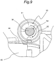
- FIG. 9 shows an enlarged view of a main portion of the first opening/closing mechanism part 30 and the driver part 40 in the air-conditioner indoor unit 1 with the opening/closing panel 12 (shown in Figs. 1 to 4 ) in an open state. While the opening/closing panel 12 is in the open state, the drive shaft 36 and the cam 50 rotate in a direction of arrow R2 as shown in Fig. 9 , where the ON region 52 of the cam 50 moves downward, by which the ON region 52 of the cam 50 presses down the lever 44 of the detection switch 43, causing the detection switch 43 to be turned ON.
- Fig. 10 shows a block diagram of the air-conditioner indoor unit 1.
- a control section 60 shown in Fig. 10 which is made up of a microcomputer, an input/output circuit and the like, controls operations of a fan motor 61, a flap motor 62, the panel driving motor 42 and the like according to commands from a remote controller (not shown) as well. Also, upon an opening/closing operation of the opening/closing panel 12, the control section 60 checks an opening/closing state of the opening/closing panel 12 according to a detection signal of the detection switch 43 mounted on the driver part 40 (shown in Figs. 5 and 7 ).
- the first opening/closing mechanism part 30 and the second opening/closing mechanism part for opening and closing the opening/closing panel 12 are placed on the front panel 11, while the driver part 40 for driving the first opening/closing mechanism part 30 and the second opening/closing mechanism part is placed on the bottom frame 10, so that the first opening/closing mechanism part 30 and the second opening/closing mechanism part are driven by the driver part 40.
- the drive shaft 36 serving as a movable part to be driven by the driver part 40 is rotated, and based on the rotation of the drive shaft 36, an opening/closing state of the opening/closing panel 12 is detected by the detection switch 43 that is an opening/closing detection part placed on the bottom frame 10. Accordingly, since the opening/closing detection part for detecting the opening/closing state of the opening/closing panel 12 is not provided on the front panel 11 side, the need for connecting electrical parts on the front panel 11 side and on the bottom frame 10 side to each other via a junction harness is eliminated. Thus, the opening/closing state of the opening/closing panel 12 can be detected with a simple construction, so that the assemblability, maintainability and reliability can be improved.
- a microswitch may be used as the detection switch 43 as an opening/closing state detection part, so that the opening/closing state of the opening/closing panel 12 can be detected accurately and reliably.
- the detection switch 43 detects an opening/closing state of the opening/closing panel 12 based on the cam 50 that rotates along with rotation of the drive shaft 36, the opening/closing state of the opening/closing panel 12 can be detected accurately and reliably.
- first opening/closing mechanism part 30 is driven by the driver part 40, and the second opening/closing mechanism part is driven via the drive shaft 36 that transmits driving force of the driver part 40, by which the opening/closing panel 12 is opened and closed by the first and second opening/closing mechanism parts 30 on the left and right of the front panel 11.
- opening/closing driving force is given to both left and right sides of the opening/closing panel 12, so that opening/closing operations of the opening/closing panel 12 can be fulfilled smoothly and evenly.
- an opening/closing state of the opening/closing panel 12 is detected by detecting the rotation of the cam 50 provided on the drive shaft 36, which is a movable part.
- the opening/closing detection part and the movable part are not limited to these, and for example, an optical sensor may also be used as the opening/closing detection part placed on the bottom frame, so that motions of the movable part of the opening/closing mechanism placed on the front panel is detected.
- the present invention may also be applied to air-conditioner indoor units in which an opening/closing panel having one or more intermediate open states between a fully open state and a fully closed state of the opening/closing panel is opened and closed in multiple stages.
- the foregoing embodiment has been described on an air-conditioner indoor unit in which the front panel 11 is removably fitted on the front face side of the bottom frame 10
- the invention may also be applied to air-conditioner indoor units in which the front panel is fitted on the front face side of the bottom frame so as to be freely openable and closable.
Landscapes
- Engineering & Computer Science (AREA)
- Chemical & Material Sciences (AREA)
- Combustion & Propulsion (AREA)
- Mechanical Engineering (AREA)
- General Engineering & Computer Science (AREA)
- Physics & Mathematics (AREA)
- Thermal Sciences (AREA)
- Air Filters, Heat-Exchange Apparatuses, And Housings Of Air-Conditioning Units (AREA)
Claims (8)
- Innenraumeinheit für Klimaanlagen, umfassend:einen Bodenrahmen (10);eine Frontplatte (11), die auf einer vorderen Stirnseite des Bodenrahmens (10) derart angebracht ist, dass sie entfernbar oder öffenbar und schließbar ist, wobei die Frontplatte (11) eine Einlassöffnung (11a) aufweist;eine Öffnungs-/Schließplatte (12) zum Öffnen und Schließen einer Einlassöffnung der Frontplatte (11);einen Öffnungs-/Schließmechanismus (30), der an der Frontplatte (11) angeordnet ist und der zum Öffnen und Schließen der Öffnungs-/Schließplatte (12) dient, wobei der Öffnungs-/Schließmechanismus (30) ein bewegliches Teil (36, 50) aufweist; undein am Bodenrahmen (10) angeordnetes Antriebsteil (40), welches zum Antrieb des Öffnungs-/Schließmechanismus (30) dient;dadurch gekennzeichnet, dass die Innenraumeinheit ferner ein auf dem Bodenrahmen (10) angeordnetes Öffnungs-/Schließerfassungsteil (43) aufweist, das zur Erfassung eines Öffnungs-/Schließzustandes der Öffnungs-/Schließplatte (12) basierend auf einer Bewegung des beweglichen Teils des Öffnungs-/Schließmechanismus (30), das auf der Frontplatte angeordnet ist und durch das Antriebsteil (40) angetrieben wird, dient.
- Innenraumeinheit für Klimaanlagen nach Anspruch 1, bei der
der Öffnungs-/Schließmechanismus (30) ein erstes Öffnungs-/Schließmechanismusteil und ein zweites Öffnungs-/Schließmechanismusteil aufweist, die durch das bewegliche Teil miteinander verbunden sind. - Innenraumeinheit für Klimaanlagen nach Anspruch 1 oder 2, bei der
das bewegliche Teil des Öffnungs-/Schließmechanismus (30) eine Antriebswelle (36) aufweist, die sich durch eine Antriebskraft des Antriebsteils (40) dreht, und
das Öffnungs-/Schließerfassungsteil (43) basierend auf der Drehung der Antriebswelle (36) einen Öffnungs-/Schließzustand der Öffnungs-/Schließplatte (12) erfasst. - Innenraumeinheit für Klimaanlagen nach Anspruch 3, bei der
das bewegliche Teil des Öffnungs-/Schließmechanismus (30) einen Nocken (50) aufweist, der sich zusammen mit der Drehung der Antriebswelle (36) dreht, und
das Öffnungs-/Schließerfassungsteil (43) basierend auf einer Drehung des Nockens (50) des Öffnungs-/Schließmechanismus (30) einen Öffnungs-/Schließzustand der Öffnungs-/Schließplatte (12) erfasst. - Innenraumeinheit für Klimaanlagen nach Anspruch 4, bei der
das Öffnungs-/Schließerfassungsteil (43) einen Hebel (44) aufweist, der mit einer Nockenfläche des Nockens (50) in Kontakt kommt, und das Öffnungs-/Schließerfassungsteil (43) durch einen Mikroschalter vorgesehen ist, der in Reaktion auf Bewegungen des Nockens (50) ein- und ausgeschaltet wird. - Innenraumeinheit für Klimaanlagen nach einem der Ansprüche 3 bis 5, bei der
der Öffnungs-/Schließmechanismus (30) ein erstes Öffnungs-/Schließmechanismusteil und ein zweites Öffnungs-/Schließmechanismusteil aufweist, die nahe der linken und rechten Seitenfläche der Frontplatte (11) vorgesehen sind und die durch die Antriebswelle (36) miteinander verbunden sind, und
da entweder das erste oder das zweite Öffnungs-/Schließmechanismusteil durch das Antriebsteil (40) angetrieben wird, wird das andere von dem ersten und zweiten Öffnungs-/Schließmechanismusteil über die Antriebswelle (36) angetrieben, die die Antriebskraft des Antriebsteils (40) überträgt. - Innenraumeinheit für Klimaanlagen nach Anspruch 5, bei der
die Nockenfläche des Nockens (50) einen EIN-Bereich (52) und einen AUS-Bereich (51) aufweist, und
während sich die Öffnungs-/Schließplatte (12) in einem geschlossenen Zustand befindet, der Hebel (44) auf dem AUS-Bereich (51) der Nockenfläche positioniert ist, und während sich die Öffnungs-/Schließplatte (12) in einem offenen Zustand befindet, der Hebel (44) auf dem EIN-Bereich (52) der Nockenoberfläche positioniert ist. - Innenraumeinheit für Klimaanlagen nach einem der Ansprüche 1 bis 7, bei der
die Innenraumeinheit ferner einen Steuerabschnitt (60) zum Steuern des Antriebsteils (40) aufweist, und
dass bei einem Öffnungs-/Schließvorgang der Öffnungs-/Schließplatte (12) der Steuerabschnitt (60) einen Öffnungs-/Schließzustand der Öffnungs-/Schließplatte (12) gemäß einem Erfassungssignal des Öffnungs-/Schließerfassungsteils (43) prüft.
Applications Claiming Priority (2)
| Application Number | Priority Date | Filing Date | Title |
|---|---|---|---|
| JP2005345566A JP4059267B2 (ja) | 2005-11-30 | 2005-11-30 | 空気調和機の室内機 |
| PCT/JP2006/323156 WO2007063737A1 (ja) | 2005-11-30 | 2006-11-21 | 空気調和機の室内機 |
Publications (3)
| Publication Number | Publication Date |
|---|---|
| EP1962028A1 EP1962028A1 (de) | 2008-08-27 |
| EP1962028A4 EP1962028A4 (de) | 2013-03-27 |
| EP1962028B1 true EP1962028B1 (de) | 2017-01-04 |
Family
ID=38092072
Family Applications (1)
| Application Number | Title | Priority Date | Filing Date |
|---|---|---|---|
| EP06833006.7A Active EP1962028B1 (de) | 2005-11-30 | 2006-11-21 | Innenraumeinheit für klimaanlage |
Country Status (4)
| Country | Link |
|---|---|
| EP (1) | EP1962028B1 (de) |
| JP (1) | JP4059267B2 (de) |
| ES (1) | ES2612763T3 (de) |
| WO (1) | WO2007063737A1 (de) |
Families Citing this family (4)
| Publication number | Priority date | Publication date | Assignee | Title |
|---|---|---|---|---|
| JP5471499B2 (ja) * | 2010-01-22 | 2014-04-16 | ダイキン工業株式会社 | 室内機 |
| JP5593708B2 (ja) * | 2010-01-22 | 2014-09-24 | ダイキン工業株式会社 | 空調室内機 |
| JP2011163613A (ja) * | 2010-02-08 | 2011-08-25 | Fujitsu General Ltd | 空気調和機 |
| CN108954768A (zh) * | 2018-08-24 | 2018-12-07 | 珠海格力电器股份有限公司 | 一种驱动机构、进风面板装置和空调器 |
Family Cites Families (5)
| Publication number | Priority date | Publication date | Assignee | Title |
|---|---|---|---|---|
| JPH07217985A (ja) * | 1993-12-10 | 1995-08-18 | Fujitsu General Ltd | 空気調和機 |
| ES2229298T3 (es) * | 1996-06-26 | 2005-04-16 | Kabushiki Kaisha Toshiba | Unidad interior para sistema de aire acondicionado. |
| JP2001049924A (ja) * | 1999-08-09 | 2001-02-20 | Aisin Seiki Co Ltd | ドアクローザ装置 |
| JP3846583B2 (ja) * | 2002-10-22 | 2006-11-15 | 三菱電機株式会社 | 空気調和機の送風装置 |
| JP3641722B2 (ja) * | 2003-09-30 | 2005-04-27 | ダイキン工業株式会社 | 空気調和機の室内機 |
-
2005
- 2005-11-30 JP JP2005345566A patent/JP4059267B2/ja not_active Expired - Fee Related
-
2006
- 2006-11-21 ES ES06833006.7T patent/ES2612763T3/es active Active
- 2006-11-21 EP EP06833006.7A patent/EP1962028B1/de active Active
- 2006-11-21 WO PCT/JP2006/323156 patent/WO2007063737A1/ja active Application Filing
Non-Patent Citations (1)
| Title |
|---|
| None * |
Also Published As
| Publication number | Publication date |
|---|---|
| EP1962028A4 (de) | 2013-03-27 |
| WO2007063737A1 (ja) | 2007-06-07 |
| JP2007147215A (ja) | 2007-06-14 |
| JP4059267B2 (ja) | 2008-03-12 |
| ES2612763T3 (es) | 2017-05-18 |
| EP1962028A1 (de) | 2008-08-27 |
Similar Documents
| Publication | Publication Date | Title |
|---|---|---|
| EP2752625B1 (de) | Klimaanlage | |
| JPH09196442A (ja) | 空気調和機の吸入口及び吐出口の開閉装置並びにその制御方法 | |
| US20090100851A1 (en) | Indoor unit of air conditioner | |
| JPH0755230A (ja) | 空気調和器の吐出口開閉装置およびその制御方法 | |
| EP2202468B1 (de) | Klimaanlagenvorrichtung | |
| EP1962028B1 (de) | Innenraumeinheit für klimaanlage | |
| JP3194896B2 (ja) | 空気調和機の開閉制御装置およびその方法 | |
| KR101482122B1 (ko) | 공기조화기 | |
| JP4703336B2 (ja) | 空気調和機 | |
| KR19980019767A (ko) | 공기조화기의 풍향제어장치 및 그 방법 | |
| JP5053914B2 (ja) | 空気調和機 | |
| KR100187280B1 (ko) | 공기조화기의 운전제어장치 및 그 방법 | |
| JPH1096551A (ja) | 空気調和機の自動扉制御装置およびその方法 | |
| JP5184948B2 (ja) | 空気調和機 | |
| JP5059661B2 (ja) | 空気調和機 | |
| JP5038092B2 (ja) | 空気調和機 | |
| KR100936496B1 (ko) | 공기조화기 | |
| JP4950100B2 (ja) | 空気調和機 | |
| KR100231025B1 (ko) | 공기조화기의 운전제어장치 및 그 방법 | |
| KR100225647B1 (ko) | 공기조화기의 개폐제어장치 및 그 방법 | |
| CN111102649B (zh) | 空调机 | |
| KR100551198B1 (ko) | 공기조화기의 토출구 개폐 제어방법 | |
| KR0182578B1 (ko) | 공기조화기의 운전제어장치 및 그 방법 | |
| KR100353935B1 (ko) | 자동차의에어덕트도어제어장치 | |
| KR20080074425A (ko) | 자동차용 공조장치의 제어방법 |
Legal Events
| Date | Code | Title | Description |
|---|---|---|---|
| PUAI | Public reference made under article 153(3) epc to a published international application that has entered the european phase |
Free format text: ORIGINAL CODE: 0009012 |
|
| 17P | Request for examination filed |
Effective date: 20080626 |
|
| AK | Designated contracting states |
Kind code of ref document: A1 Designated state(s): AT BE BG CH CY CZ DE DK EE ES FI FR GB GR HU IE IS IT LI LT LU LV MC NL PL PT RO SE SI SK TR |
|
| DAX | Request for extension of the european patent (deleted) | ||
| A4 | Supplementary search report drawn up and despatched |
Effective date: 20130226 |
|
| RIC1 | Information provided on ipc code assigned before grant |
Ipc: F24F 1/00 20110101AFI20130220BHEP |
|
| GRAP | Despatch of communication of intention to grant a patent |
Free format text: ORIGINAL CODE: EPIDOSNIGR1 |
|
| INTG | Intention to grant announced |
Effective date: 20160721 |
|
| GRAS | Grant fee paid |
Free format text: ORIGINAL CODE: EPIDOSNIGR3 |
|
| GRAA | (expected) grant |
Free format text: ORIGINAL CODE: 0009210 |
|
| AK | Designated contracting states |
Kind code of ref document: B1 Designated state(s): AT BE BG CH CY CZ DE DK EE ES FI FR GB GR HU IE IS IT LI LT LU LV MC NL PL PT RO SE SI SK TR |
|
| REG | Reference to a national code |
Ref country code: GB Ref legal event code: FG4D |
|
| REG | Reference to a national code |
Ref country code: CH Ref legal event code: EP |
|
| REG | Reference to a national code |
Ref country code: AT Ref legal event code: REF Ref document number: 859633 Country of ref document: AT Kind code of ref document: T Effective date: 20170115 |
|
| REG | Reference to a national code |
Ref country code: IE Ref legal event code: FG4D |
|
| REG | Reference to a national code |
Ref country code: DE Ref legal event code: R096 Ref document number: 602006051466 Country of ref document: DE |
|
| REG | Reference to a national code |
Ref country code: LT Ref legal event code: MG4D Ref country code: NL Ref legal event code: MP Effective date: 20170104 |
|
| REG | Reference to a national code |
Ref country code: ES Ref legal event code: FG2A Ref document number: 2612763 Country of ref document: ES Kind code of ref document: T3 Effective date: 20170518 |
|
| REG | Reference to a national code |
Ref country code: AT Ref legal event code: MK05 Ref document number: 859633 Country of ref document: AT Kind code of ref document: T Effective date: 20170104 |
|
| PG25 | Lapsed in a contracting state [announced via postgrant information from national office to epo] |
Ref country code: NL Free format text: LAPSE BECAUSE OF FAILURE TO SUBMIT A TRANSLATION OF THE DESCRIPTION OR TO PAY THE FEE WITHIN THE PRESCRIBED TIME-LIMIT Effective date: 20170104 |
|
| PG25 | Lapsed in a contracting state [announced via postgrant information from national office to epo] |
Ref country code: IS Free format text: LAPSE BECAUSE OF FAILURE TO SUBMIT A TRANSLATION OF THE DESCRIPTION OR TO PAY THE FEE WITHIN THE PRESCRIBED TIME-LIMIT Effective date: 20170504 Ref country code: GR Free format text: LAPSE BECAUSE OF FAILURE TO SUBMIT A TRANSLATION OF THE DESCRIPTION OR TO PAY THE FEE WITHIN THE PRESCRIBED TIME-LIMIT Effective date: 20170405 Ref country code: LT Free format text: LAPSE BECAUSE OF FAILURE TO SUBMIT A TRANSLATION OF THE DESCRIPTION OR TO PAY THE FEE WITHIN THE PRESCRIBED TIME-LIMIT Effective date: 20170104 Ref country code: FI Free format text: LAPSE BECAUSE OF FAILURE TO SUBMIT A TRANSLATION OF THE DESCRIPTION OR TO PAY THE FEE WITHIN THE PRESCRIBED TIME-LIMIT Effective date: 20170104 |
|
| PG25 | Lapsed in a contracting state [announced via postgrant information from national office to epo] |
Ref country code: PT Free format text: LAPSE BECAUSE OF FAILURE TO SUBMIT A TRANSLATION OF THE DESCRIPTION OR TO PAY THE FEE WITHIN THE PRESCRIBED TIME-LIMIT Effective date: 20170504 Ref country code: BG Free format text: LAPSE BECAUSE OF FAILURE TO SUBMIT A TRANSLATION OF THE DESCRIPTION OR TO PAY THE FEE WITHIN THE PRESCRIBED TIME-LIMIT Effective date: 20170404 Ref country code: PL Free format text: LAPSE BECAUSE OF FAILURE TO SUBMIT A TRANSLATION OF THE DESCRIPTION OR TO PAY THE FEE WITHIN THE PRESCRIBED TIME-LIMIT Effective date: 20170104 Ref country code: LV Free format text: LAPSE BECAUSE OF FAILURE TO SUBMIT A TRANSLATION OF THE DESCRIPTION OR TO PAY THE FEE WITHIN THE PRESCRIBED TIME-LIMIT Effective date: 20170104 Ref country code: SE Free format text: LAPSE BECAUSE OF FAILURE TO SUBMIT A TRANSLATION OF THE DESCRIPTION OR TO PAY THE FEE WITHIN THE PRESCRIBED TIME-LIMIT Effective date: 20170104 Ref country code: AT Free format text: LAPSE BECAUSE OF FAILURE TO SUBMIT A TRANSLATION OF THE DESCRIPTION OR TO PAY THE FEE WITHIN THE PRESCRIBED TIME-LIMIT Effective date: 20170104 |
|
| REG | Reference to a national code |
Ref country code: DE Ref legal event code: R097 Ref document number: 602006051466 Country of ref document: DE |
|
| REG | Reference to a national code |
Ref country code: FR Ref legal event code: PLFP Year of fee payment: 12 |
|
| PG25 | Lapsed in a contracting state [announced via postgrant information from national office to epo] |
Ref country code: SK Free format text: LAPSE BECAUSE OF FAILURE TO SUBMIT A TRANSLATION OF THE DESCRIPTION OR TO PAY THE FEE WITHIN THE PRESCRIBED TIME-LIMIT Effective date: 20170104 Ref country code: EE Free format text: LAPSE BECAUSE OF FAILURE TO SUBMIT A TRANSLATION OF THE DESCRIPTION OR TO PAY THE FEE WITHIN THE PRESCRIBED TIME-LIMIT Effective date: 20170104 Ref country code: RO Free format text: LAPSE BECAUSE OF FAILURE TO SUBMIT A TRANSLATION OF THE DESCRIPTION OR TO PAY THE FEE WITHIN THE PRESCRIBED TIME-LIMIT Effective date: 20170104 Ref country code: CZ Free format text: LAPSE BECAUSE OF FAILURE TO SUBMIT A TRANSLATION OF THE DESCRIPTION OR TO PAY THE FEE WITHIN THE PRESCRIBED TIME-LIMIT Effective date: 20170104 |
|
| PLBE | No opposition filed within time limit |
Free format text: ORIGINAL CODE: 0009261 |
|
| STAA | Information on the status of an ep patent application or granted ep patent |
Free format text: STATUS: NO OPPOSITION FILED WITHIN TIME LIMIT |
|
| PG25 | Lapsed in a contracting state [announced via postgrant information from national office to epo] |
Ref country code: DK Free format text: LAPSE BECAUSE OF FAILURE TO SUBMIT A TRANSLATION OF THE DESCRIPTION OR TO PAY THE FEE WITHIN THE PRESCRIBED TIME-LIMIT Effective date: 20170104 |
|
| 26N | No opposition filed |
Effective date: 20171005 |
|
| PG25 | Lapsed in a contracting state [announced via postgrant information from national office to epo] |
Ref country code: SI Free format text: LAPSE BECAUSE OF FAILURE TO SUBMIT A TRANSLATION OF THE DESCRIPTION OR TO PAY THE FEE WITHIN THE PRESCRIBED TIME-LIMIT Effective date: 20170104 |
|
| PG25 | Lapsed in a contracting state [announced via postgrant information from national office to epo] |
Ref country code: MC Free format text: LAPSE BECAUSE OF FAILURE TO SUBMIT A TRANSLATION OF THE DESCRIPTION OR TO PAY THE FEE WITHIN THE PRESCRIBED TIME-LIMIT Effective date: 20170104 |
|
| PG25 | Lapsed in a contracting state [announced via postgrant information from national office to epo] |
Ref country code: LI Free format text: LAPSE BECAUSE OF NON-PAYMENT OF DUE FEES Effective date: 20171130 Ref country code: CH Free format text: LAPSE BECAUSE OF NON-PAYMENT OF DUE FEES Effective date: 20171130 |
|
| PG25 | Lapsed in a contracting state [announced via postgrant information from national office to epo] |
Ref country code: LU Free format text: LAPSE BECAUSE OF NON-PAYMENT OF DUE FEES Effective date: 20171121 |
|
| REG | Reference to a national code |
Ref country code: BE Ref legal event code: MM Effective date: 20171130 |
|
| REG | Reference to a national code |
Ref country code: IE Ref legal event code: MM4A |
|
| REG | Reference to a national code |
Ref country code: FR Ref legal event code: PLFP Year of fee payment: 13 |
|
| PG25 | Lapsed in a contracting state [announced via postgrant information from national office to epo] |
Ref country code: IE Free format text: LAPSE BECAUSE OF NON-PAYMENT OF DUE FEES Effective date: 20171121 |
|
| PG25 | Lapsed in a contracting state [announced via postgrant information from national office to epo] |
Ref country code: BE Free format text: LAPSE BECAUSE OF NON-PAYMENT OF DUE FEES Effective date: 20171130 |
|
| PG25 | Lapsed in a contracting state [announced via postgrant information from national office to epo] |
Ref country code: HU Free format text: LAPSE BECAUSE OF FAILURE TO SUBMIT A TRANSLATION OF THE DESCRIPTION OR TO PAY THE FEE WITHIN THE PRESCRIBED TIME-LIMIT; INVALID AB INITIO Effective date: 20061121 |
|
| PG25 | Lapsed in a contracting state [announced via postgrant information from national office to epo] |
Ref country code: CY Free format text: LAPSE BECAUSE OF NON-PAYMENT OF DUE FEES Effective date: 20170104 |
|
| PG25 | Lapsed in a contracting state [announced via postgrant information from national office to epo] |
Ref country code: TR Free format text: LAPSE BECAUSE OF FAILURE TO SUBMIT A TRANSLATION OF THE DESCRIPTION OR TO PAY THE FEE WITHIN THE PRESCRIBED TIME-LIMIT Effective date: 20170104 |
|
| PGFP | Annual fee paid to national office [announced via postgrant information from national office to epo] |
Ref country code: GB Payment date: 20230928 Year of fee payment: 18 |
|
| PGFP | Annual fee paid to national office [announced via postgrant information from national office to epo] |
Ref country code: FR Payment date: 20230929 Year of fee payment: 18 |
|
| PGFP | Annual fee paid to national office [announced via postgrant information from national office to epo] |
Ref country code: ES Payment date: 20231201 Year of fee payment: 18 |
|
| PGFP | Annual fee paid to national office [announced via postgrant information from national office to epo] |
Ref country code: IT Payment date: 20231010 Year of fee payment: 18 Ref country code: DE Payment date: 20230929 Year of fee payment: 18 |