EP1960083B1 - Sac filtrant d'aspirateur - Google Patents
Sac filtrant d'aspirateur Download PDFInfo
- Publication number
- EP1960083B1 EP1960083B1 EP06819022.2A EP06819022A EP1960083B1 EP 1960083 B1 EP1960083 B1 EP 1960083B1 EP 06819022 A EP06819022 A EP 06819022A EP 1960083 B1 EP1960083 B1 EP 1960083B1
- Authority
- EP
- European Patent Office
- Prior art keywords
- filter bag
- bag according
- fibres
- layer
- filter
- Prior art date
- Legal status (The legal status is an assumption and is not a legal conclusion. Google has not performed a legal analysis and makes no representation as to the accuracy of the status listed.)
- Active
Links
Images


Classifications
-
- B—PERFORMING OPERATIONS; TRANSPORTING
- B01—PHYSICAL OR CHEMICAL PROCESSES OR APPARATUS IN GENERAL
- B01D—SEPARATION
- B01D39/00—Filtering material for liquid or gaseous fluids
- B01D39/14—Other self-supporting filtering material ; Other filtering material
- B01D39/16—Other self-supporting filtering material ; Other filtering material of organic material, e.g. synthetic fibres
-
- B—PERFORMING OPERATIONS; TRANSPORTING
- B32—LAYERED PRODUCTS
- B32B—LAYERED PRODUCTS, i.e. PRODUCTS BUILT-UP OF STRATA OF FLAT OR NON-FLAT, e.g. CELLULAR OR HONEYCOMB, FORM
- B32B5/00—Layered products characterised by the non- homogeneity or physical structure, i.e. comprising a fibrous, filamentary, particulate or foam layer; Layered products characterised by having a layer differing constitutionally or physically in different parts
- B32B5/22—Layered products characterised by the non- homogeneity or physical structure, i.e. comprising a fibrous, filamentary, particulate or foam layer; Layered products characterised by having a layer differing constitutionally or physically in different parts characterised by the presence of two or more layers which are next to each other and are fibrous, filamentary, formed of particles or foamed
- B32B5/24—Layered products characterised by the non- homogeneity or physical structure, i.e. comprising a fibrous, filamentary, particulate or foam layer; Layered products characterised by having a layer differing constitutionally or physically in different parts characterised by the presence of two or more layers which are next to each other and are fibrous, filamentary, formed of particles or foamed one layer being a fibrous or filamentary layer
- B32B5/26—Layered products characterised by the non- homogeneity or physical structure, i.e. comprising a fibrous, filamentary, particulate or foam layer; Layered products characterised by having a layer differing constitutionally or physically in different parts characterised by the presence of two or more layers which are next to each other and are fibrous, filamentary, formed of particles or foamed one layer being a fibrous or filamentary layer another layer next to it also being fibrous or filamentary
-
- A—HUMAN NECESSITIES
- A47—FURNITURE; DOMESTIC ARTICLES OR APPLIANCES; COFFEE MILLS; SPICE MILLS; SUCTION CLEANERS IN GENERAL
- A47L—DOMESTIC WASHING OR CLEANING; SUCTION CLEANERS IN GENERAL
- A47L9/00—Details or accessories of suction cleaners, e.g. mechanical means for controlling the suction or for effecting pulsating action; Storing devices specially adapted to suction cleaners or parts thereof; Carrying-vehicles specially adapted for suction cleaners
- A47L9/10—Filters; Dust separators; Dust removal; Automatic exchange of filters
- A47L9/14—Bags or the like; Rigid filtering receptacles; Attachment of, or closures for, bags or receptacles
-
- B—PERFORMING OPERATIONS; TRANSPORTING
- B01—PHYSICAL OR CHEMICAL PROCESSES OR APPARATUS IN GENERAL
- B01D—SEPARATION
- B01D39/00—Filtering material for liquid or gaseous fluids
- B01D39/14—Other self-supporting filtering material ; Other filtering material
- B01D39/16—Other self-supporting filtering material ; Other filtering material of organic material, e.g. synthetic fibres
- B01D39/1607—Other self-supporting filtering material ; Other filtering material of organic material, e.g. synthetic fibres the material being fibrous
- B01D39/1623—Other self-supporting filtering material ; Other filtering material of organic material, e.g. synthetic fibres the material being fibrous of synthetic origin
- B01D39/163—Other self-supporting filtering material ; Other filtering material of organic material, e.g. synthetic fibres the material being fibrous of synthetic origin sintered or bonded
-
- B—PERFORMING OPERATIONS; TRANSPORTING
- B32—LAYERED PRODUCTS
- B32B—LAYERED PRODUCTS, i.e. PRODUCTS BUILT-UP OF STRATA OF FLAT OR NON-FLAT, e.g. CELLULAR OR HONEYCOMB, FORM
- B32B29/00—Layered products comprising a layer of paper or cardboard
- B32B29/02—Layered products comprising a layer of paper or cardboard next to a fibrous or filamentary layer
-
- B—PERFORMING OPERATIONS; TRANSPORTING
- B32—LAYERED PRODUCTS
- B32B—LAYERED PRODUCTS, i.e. PRODUCTS BUILT-UP OF STRATA OF FLAT OR NON-FLAT, e.g. CELLULAR OR HONEYCOMB, FORM
- B32B3/00—Layered products comprising a layer with external or internal discontinuities or unevennesses, or a layer of non-planar shape; Layered products comprising a layer having particular features of form
- B32B3/26—Layered products comprising a layer with external or internal discontinuities or unevennesses, or a layer of non-planar shape; Layered products comprising a layer having particular features of form characterised by a particular shape of the outline of the cross-section of a continuous layer; characterised by a layer with cavities or internal voids ; characterised by an apertured layer
-
- B—PERFORMING OPERATIONS; TRANSPORTING
- B32—LAYERED PRODUCTS
- B32B—LAYERED PRODUCTS, i.e. PRODUCTS BUILT-UP OF STRATA OF FLAT OR NON-FLAT, e.g. CELLULAR OR HONEYCOMB, FORM
- B32B5/00—Layered products characterised by the non- homogeneity or physical structure, i.e. comprising a fibrous, filamentary, particulate or foam layer; Layered products characterised by having a layer differing constitutionally or physically in different parts
- B32B5/02—Layered products characterised by the non- homogeneity or physical structure, i.e. comprising a fibrous, filamentary, particulate or foam layer; Layered products characterised by having a layer differing constitutionally or physically in different parts characterised by structural features of a fibrous or filamentary layer
- B32B5/022—Non-woven fabric
-
- D—TEXTILES; PAPER
- D04—BRAIDING; LACE-MAKING; KNITTING; TRIMMINGS; NON-WOVEN FABRICS
- D04H—MAKING TEXTILE FABRICS, e.g. FROM FIBRES OR FILAMENTARY MATERIAL; FABRICS MADE BY SUCH PROCESSES OR APPARATUS, e.g. FELTS, NON-WOVEN FABRICS; COTTON-WOOL; WADDING ; NON-WOVEN FABRICS FROM STAPLE FIBRES, FILAMENTS OR YARNS, BONDED WITH AT LEAST ONE WEB-LIKE MATERIAL DURING THEIR CONSOLIDATION
- D04H1/00—Non-woven fabrics formed wholly or mainly of staple fibres or like relatively short fibres
- D04H1/40—Non-woven fabrics formed wholly or mainly of staple fibres or like relatively short fibres from fleeces or layers composed of fibres without existing or potential cohesive properties
- D04H1/42—Non-woven fabrics formed wholly or mainly of staple fibres or like relatively short fibres from fleeces or layers composed of fibres without existing or potential cohesive properties characterised by the use of certain kinds of fibres insofar as this use has no preponderant influence on the consolidation of the fleece
- D04H1/4282—Addition polymers
- D04H1/4291—Olefin series
-
- D—TEXTILES; PAPER
- D04—BRAIDING; LACE-MAKING; KNITTING; TRIMMINGS; NON-WOVEN FABRICS
- D04H—MAKING TEXTILE FABRICS, e.g. FROM FIBRES OR FILAMENTARY MATERIAL; FABRICS MADE BY SUCH PROCESSES OR APPARATUS, e.g. FELTS, NON-WOVEN FABRICS; COTTON-WOOL; WADDING ; NON-WOVEN FABRICS FROM STAPLE FIBRES, FILAMENTS OR YARNS, BONDED WITH AT LEAST ONE WEB-LIKE MATERIAL DURING THEIR CONSOLIDATION
- D04H1/00—Non-woven fabrics formed wholly or mainly of staple fibres or like relatively short fibres
- D04H1/40—Non-woven fabrics formed wholly or mainly of staple fibres or like relatively short fibres from fleeces or layers composed of fibres without existing or potential cohesive properties
- D04H1/54—Non-woven fabrics formed wholly or mainly of staple fibres or like relatively short fibres from fleeces or layers composed of fibres without existing or potential cohesive properties by welding together the fibres, e.g. by partially melting or dissolving
- D04H1/555—Non-woven fabrics formed wholly or mainly of staple fibres or like relatively short fibres from fleeces or layers composed of fibres without existing or potential cohesive properties by welding together the fibres, e.g. by partially melting or dissolving by ultrasonic heating
-
- D—TEXTILES; PAPER
- D04—BRAIDING; LACE-MAKING; KNITTING; TRIMMINGS; NON-WOVEN FABRICS
- D04H—MAKING TEXTILE FABRICS, e.g. FROM FIBRES OR FILAMENTARY MATERIAL; FABRICS MADE BY SUCH PROCESSES OR APPARATUS, e.g. FELTS, NON-WOVEN FABRICS; COTTON-WOOL; WADDING ; NON-WOVEN FABRICS FROM STAPLE FIBRES, FILAMENTS OR YARNS, BONDED WITH AT LEAST ONE WEB-LIKE MATERIAL DURING THEIR CONSOLIDATION
- D04H1/00—Non-woven fabrics formed wholly or mainly of staple fibres or like relatively short fibres
- D04H1/40—Non-woven fabrics formed wholly or mainly of staple fibres or like relatively short fibres from fleeces or layers composed of fibres without existing or potential cohesive properties
- D04H1/54—Non-woven fabrics formed wholly or mainly of staple fibres or like relatively short fibres from fleeces or layers composed of fibres without existing or potential cohesive properties by welding together the fibres, e.g. by partially melting or dissolving
- D04H1/559—Non-woven fabrics formed wholly or mainly of staple fibres or like relatively short fibres from fleeces or layers composed of fibres without existing or potential cohesive properties by welding together the fibres, e.g. by partially melting or dissolving the fibres being within layered webs
-
- D—TEXTILES; PAPER
- D04—BRAIDING; LACE-MAKING; KNITTING; TRIMMINGS; NON-WOVEN FABRICS
- D04H—MAKING TEXTILE FABRICS, e.g. FROM FIBRES OR FILAMENTARY MATERIAL; FABRICS MADE BY SUCH PROCESSES OR APPARATUS, e.g. FELTS, NON-WOVEN FABRICS; COTTON-WOOL; WADDING ; NON-WOVEN FABRICS FROM STAPLE FIBRES, FILAMENTS OR YARNS, BONDED WITH AT LEAST ONE WEB-LIKE MATERIAL DURING THEIR CONSOLIDATION
- D04H13/00—Other non-woven fabrics
-
- B—PERFORMING OPERATIONS; TRANSPORTING
- B32—LAYERED PRODUCTS
- B32B—LAYERED PRODUCTS, i.e. PRODUCTS BUILT-UP OF STRATA OF FLAT OR NON-FLAT, e.g. CELLULAR OR HONEYCOMB, FORM
- B32B2310/00—Treatment by energy or chemical effects
- B32B2310/028—Treatment by energy or chemical effects using vibration, e.g. sonic or ultrasonic
-
- B—PERFORMING OPERATIONS; TRANSPORTING
- B32—LAYERED PRODUCTS
- B32B—LAYERED PRODUCTS, i.e. PRODUCTS BUILT-UP OF STRATA OF FLAT OR NON-FLAT, e.g. CELLULAR OR HONEYCOMB, FORM
- B32B2317/00—Animal or vegetable based
- B32B2317/12—Paper, e.g. cardboard
-
- B—PERFORMING OPERATIONS; TRANSPORTING
- B32—LAYERED PRODUCTS
- B32B—LAYERED PRODUCTS, i.e. PRODUCTS BUILT-UP OF STRATA OF FLAT OR NON-FLAT, e.g. CELLULAR OR HONEYCOMB, FORM
- B32B2432/00—Cleaning articles, e.g. mops or wipes
-
- B—PERFORMING OPERATIONS; TRANSPORTING
- B32—LAYERED PRODUCTS
- B32B—LAYERED PRODUCTS, i.e. PRODUCTS BUILT-UP OF STRATA OF FLAT OR NON-FLAT, e.g. CELLULAR OR HONEYCOMB, FORM
- B32B2439/00—Containers; Receptacles
-
- B—PERFORMING OPERATIONS; TRANSPORTING
- B32—LAYERED PRODUCTS
- B32B—LAYERED PRODUCTS, i.e. PRODUCTS BUILT-UP OF STRATA OF FLAT OR NON-FLAT, e.g. CELLULAR OR HONEYCOMB, FORM
- B32B2509/00—Household appliances
-
- Y—GENERAL TAGGING OF NEW TECHNOLOGICAL DEVELOPMENTS; GENERAL TAGGING OF CROSS-SECTIONAL TECHNOLOGIES SPANNING OVER SEVERAL SECTIONS OF THE IPC; TECHNICAL SUBJECTS COVERED BY FORMER USPC CROSS-REFERENCE ART COLLECTIONS [XRACs] AND DIGESTS
- Y10—TECHNICAL SUBJECTS COVERED BY FORMER USPC
- Y10S—TECHNICAL SUBJECTS COVERED BY FORMER USPC CROSS-REFERENCE ART COLLECTIONS [XRACs] AND DIGESTS
- Y10S15/00—Brushing, scrubbing, and general cleaning
- Y10S15/08—Dust bags and separators
-
- Y—GENERAL TAGGING OF NEW TECHNOLOGICAL DEVELOPMENTS; GENERAL TAGGING OF CROSS-SECTIONAL TECHNOLOGIES SPANNING OVER SEVERAL SECTIONS OF THE IPC; TECHNICAL SUBJECTS COVERED BY FORMER USPC CROSS-REFERENCE ART COLLECTIONS [XRACs] AND DIGESTS
- Y10—TECHNICAL SUBJECTS COVERED BY FORMER USPC
- Y10S—TECHNICAL SUBJECTS COVERED BY FORMER USPC CROSS-REFERENCE ART COLLECTIONS [XRACs] AND DIGESTS
- Y10S55/00—Gas separation
- Y10S55/02—Vacuum cleaner bags
Definitions
- the present invention relates to a vacuum cleaner filter bag with a filter medium comprising at least three layers, wherein at least two layers consist of a nonwoven fabric layer.
- Multilayer filter bags made of nonwovens reveal, for example, the US 4,589,894 and the US 5,647,881 Minnesota Mining and Manufacturing Company (3M). These inventions were mainly concerned with the improvement of dust separation.
- the EP 1 362 627 A1 Branofilter GmbH describes filter bags with a multi-layered structure in which the fiber diameter distributions in the coarse dust filter layer and in the fine dust filter layer are different.
- the object of the present invention to provide a filter bag whose filter material has a particularly low bulk density compared to those described in the prior art, in order to obtain a superior dust storage capacity achieve.
- the filter bag should continue to have a structure in which the structure and thus the associated advantageous properties of the unconsolidated fiber layer remain as much as possible.
- a vacuum cleaner filter bag made of a filter material comprising at least three layers with at least two layers of a nonwoven fabric layer, and at least one layer of a nonwoven layer of fibers and / or filaments, wherein the at least two nonwoven fabric layers and the at least one nonwoven fabric layer by welding together are connected.
- nonwoven fabric and nonwoven fabric in the field of production of nonwoven fabrics are delimited against each other as follows and also to be understood in the context of the present invention.
- a nonwoven fabric fibers and / or filaments are first deposited on a carrier. Methods for depositing are known from the prior art. These deposited, loose and still unbound fibers and / or filaments are referred to as non-woven web.
- nonwoven binding step such a nonwoven fabric finally forms a nonwoven fabric which has sufficient strength to be wound into rolls, for example.
- a preferred embodiment of the invention is in the welded joint with as few connections based on the entire flow-through surface of the filter bag worked. According to the present invention, this is achieved by virtue of the fact that, based on the total flow-through surface of the filter bag, an average of at most 19 welded joints per 10 cm 2 are present, preferably a maximum of 10 welded joints and particularly preferably a maximum of 5 welded joints.
- the pressing surface portion of the weld pattern is at most 5%, preferably at most 2% and particularly preferably at most 1% of the area of the filter bag which can be flowed through.
- the filter bag has the additional feature that the average total porosity is at least 65%, preferably at least 80%, very particularly preferably at least 95%.
- the average median pore diameter (average median pore diameter) is at least 120 ⁇ m, more preferably at least 150 ⁇ m, more preferably at least 180 ⁇ m and very particularly preferably at least 200 ⁇ m.
- Average median is understood to mean the arithmetic mean of several measurements of the median of the examined samples.
- the measuring method for determining the average total porosity and the average median pore diameter according to the present invention will be described with reference to FIGS FIGS. 15 to 17 described in more detail.
- the thickness and bulk (bulk) of the material is significantly increased for the same surface-related mass. Due to the low density (bulk density) of the composite, the material has a high dust storage capacity.
- the present invention is subject to no restrictions, with the proviso that a maximum of 19 welded joints per 10 cm 2 , relative to the flow-through surface of the filter bag, are present.
- the welded joints can be distributed uniformly, ie at equal intervals, over the entire surface or even unevenly.
- the invention thus also includes embodiments in which welded joints are present only in certain areas in a higher number and in which then larger open areas, which are then separated by an increased number of welded joints from a next larger free area.
- the essential criterion is always that the specified maximum number of welds is not exceeded.
- the welded joints themselves can be designed in different geometries. Thus punctiform, linear, star-shaped or bar-shaped welded joints can be used. With regard to the exact configuration of the welded joints, in addition to the number of welded joints, only the pressing surface portion of the welding pattern, which, as already stated, is at most 5%, preferably at most 2% and particularly preferably only at most 1%, is the limiting criterion.
- the nonwoven fabric layer of the invention which is present with the nonwoven fabric layer in a composite, comprises all fibers known per se in the prior art, in particular staple fibers, and / or filaments.
- staple fibers are also understood as meaning fibrillated film fibers (split fibers) and crimp fibers; the staple fibers in the sense of the invention may also be preferably electrostatically charged.
- the fibers may have a length between 1 and 100 mm, preferably between 3 and 70 mm.
- crimping fibers especially those having a spatial structure, such as e.g. a zigzag, wave and / or spiral structure.
- the advantage of such fibers is that they significantly increase the bulkiness of the medium.
- the crimping fiber can be a mechanically crimped, an autocrimping fiber and / or a bicomponent crimping fiber.
- Autocrimp fibers are eg in the European Patent 0 854 943 A1 as well as in the PCT / GB00 / 02998 described.
- bicomponent crimping pastes can be obtained from Chisso Corporation of Japan and crimped polyester staple fibers of the spiral type at Gepeco in USA.
- Staple fibers selected from natural fibers and / or man-made fibers may be used in the invention.
- chemical fibers are in particular polyolefins and polyesters.
- natural fibers are cellulose, wood fibers, kapok, flax.
- the filter bag according to the invention is subject in terms of the arrangement of the layers and the number of layers in so far no restrictions with the proviso that in each case at least two layers of a nonwoven fabric layer and at least one nonwoven fabric layer, said two layers by a welded joint, preferably by an ultrasonic welded joint, as described above, are interconnected throughout.
- the nonwoven fabric layer of the composite described above is preferably a support or carrier layer and has a basis weight of at least 5 g / m 2 .
- a scrim is conveniently used. Under a scrim is understood to mean any air-permeable material that can serve as a carrier or reinforcing layer. It may be a nonwoven fabric, a woven material or a netting. Preferably, it is made of a thermoplastic polymer to facilitate weldability with the nonwoven fabric layer.
- the nonwoven layer may be a scrim, preferably a spunbond or a meltblown nonwoven layer.
- Examples of scrims are spunbonded nonwovens (spunbond nonwovens). But it can also be dry or wet laid nonwoven fabrics, which have a sufficient mechanical stability.
- the surface-related dimensions of such a nonwoven fabric layer according to the present invention is preferably between 10 and 200 g / m 2 , more preferably between 20 and 100 g / m 2 .
- the basis weight in g / m 2 was determined according to DIN EN 29073-1. With regard to the basis weight of the nonwoven fabric layer, it should be mentioned that this is to be determined indirectly via the composite of nonwoven fabric layers and nonwoven fabric layer, since it is not possible to determine the basis weight of the nonwoven fabric layer alone because of its loose structure.
- the determination was therefore made by a subtraction method, ie the area-related mass of the entire composite, ie the composite of nonwoven fabric layers and nonwoven fabric layer, was determined and 5 then the area-related mass of the nonwoven fabric layers, which can be determined separately, deducted again.
- the thickness of the above-described composite of nonwoven fabric layer and the nonwoven fabric layer is between 1 and 7 mm, preferably between 2 and 4 mm.
- the thickness was determined according to EDANA 30.5-99 point 4.2.
- the device used was a VDM 01, available from Karl Schröder KG in Weinheim. Since the measurements according to methods 4.1, 4.2 or 4.3 gave very different results, the measurements of the composites according to the invention, i. Composites, in principle carried out according to method 4.2.
- a further fine filter spunbonded layer can be provided.
- the fine filter spunbond layers may have different filter properties.
- filter bag further layers may be provided, which are formed from paper, nonwoven material and / or nanofibers.
- the filter bag according to the invention can of course, as described above, in addition to the composite of the two nonwoven fabric layers and the nonwoven fabric layer have further layers.
- the filter bag according to the invention can continue to exhibit, as required, further fine filter layers with different filter properties.
- Fine filter spunbond layers are used here as fine filter layers.
- Fine-filter spunbonded layers according to the invention are corresponding layers which are suitable for depositing fine particles.
- Common fine fiber spunbonded fabrics are produced by the melt-blown spunbonding process (meltblowing process), the spunbonding process (flash spinning process) or the electrostatic spunbonding process (electrostatic spunbonding).
- melt-blown spunbonding process melt-blown spunbonding process
- flash spinning process the spunbonding process
- electrostatic spunbonding process electrostatic spunbonding
- the filter bag according to the invention is preferably connected to one another through a continuous ultrasonic welding connection through all layers, ie through the nonwoven fabric layers and the nonwoven fabric layer as well as the further layers.
- the filter bag according to the invention also includes embodiments in which only Sch whoverbin-Der Filter bag according to the invention is preferably connected by a continuous ultrasonic welding through all layers, ie by the nonwoven fabric layers and the nonwoven fabric layer and the other layers together.
- the filter bag according to the invention also includes embodiments in which only welded joints of the nonwoven fabric layers are present with the nonwoven fabric layer and the other layers are connected either by gluing or by another bonding method with the composite of the nonwoven fabric layers and the nonwoven fabric layer.
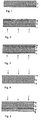
- FIGS. 1 to 9 schematically show a detail of how the filter material of the filter bag according to the invention can be constructed.
- FIG. 1 shows a two-layer structure of a layer 1 in the form of a nonwoven fabric layer, which in the FIG. 1 a scrim is.
- This scrim layer 1 is connected to a nonwoven fabric layer 2 by ultrasonic welding.
- FIG. 1 the further required according to the invention position is not shown.
- the structure of the construction of in FIG. 2 illustrated embodiment substantially corresponds to FIG. 1 , but with an additional layer of a fine filter medium 3, which represents the third layer here.
- the preferred inflow side is indicated by arrows.
- the fine filter layer 3 consists for example of a meltblown nonwoven fabric.
- FIG. 3 again shows another example, starting from the FIG. 2 , with an additional protective layer 4, which is arranged downstream.
- This protective layer 4 may be a scrim, preferably a spunbonded nonwoven.
- the embodiment which is in the FIG. 4 is shown, is connected from a layer of a nonwoven fabric 1 with a nonwoven fabric layer 2 attached thereto by welding, as described above, wherein a layer of a protective nonwoven fabric 4 is additionally connected upstream on the inflow side.
- the nonwoven fabric 1 here is in particular a meltblown nonwoven fabric.
- FIG. 5 differs from FIG. 4 by an additional downstream microfiber nonwoven fabric layer 3.
- FIG. 7 shows a laminate of 2 layers by ultrasonic welding points interconnected layers of nonwoven fabric 1, between which the nonwoven fabric layer 2 is located.
- FIG. 8 represents an embodiment of the structure according to the invention, which is of the FIG. 7 goes out, but here now with a downstream arranged layer of a filter medium.
- FIG. 9 shows a structure of FIG. 8 goes out, with an additional layer 4 downstream.
- the respective structures are described only schematically the layer sequence according to.
- the structures described above are then preferably joined together by ultrasonic welding.
- FIG. 13a Now shows in the form of a 3D graph, how the small number of welds affects the structure of the material.
- FIG. 13a Here is a material shown, as it is the structure FIG. 7 corresponds, ie it is a material that consists of a non-woven fabric layer which is connected between two layers of spunbonded by ultrasonic welding. In the example after the FIG. 13a about 0.2 welding points per cm 2 were used.
- FIG. 13a clearly shows the pillow-like training, which leads to the high bulkiness as described above.
- 100% split fibers or split fibers made of polypropylene were used as nonwoven fabric layer.
- the spunbonded nonwoven is also made of polypropylene.
- the inventive design leads to a significant increase in the dust storage capacity over the filter media, as described in the prior art, which have 2.5 welding points per cm 2 .
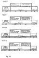
- the in the FIG. 14 The measurement results shown were carried out as follows: Vacuum cleaner used: Miele Performance 2300 Type: HS 05 Model: S749 No .: 71683038 Power setting: maximum Size of the filter bags: 295 mm x 270 mm Test substance: DMT Type8
- Test procedure The dust bag to be tested is installed in the device after the device has warmed up for 10 minutes. The volume flow without dust load is after 1 min. Read the running time of the device. Then the first portion of 50 g of dust is sucked in within 30 seconds. After 1 min. the actual volume flow (in m 3 / h) is read off. This step is repeated for the following dust additions until 400 g of dust has been added.
- Filter media Spunbond 17 g / m 2 , nonwoven 50 g / m 2 , spunbonded 17 g / m 2
- Welding pattern 1. 2.5 points / cm 2 , evenly distributed 2. 0.2 points / cm 2 , evenly distributed
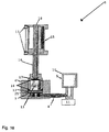
- FIG. 15 is schematically illustrated the measuring principle for determining the average total porosity and the average median pore diameter.
- FIG. 16 shows a device used in determining the average total porosity and average median pore diameter.
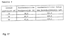
- Table 9 ( FIG. 17 ) gives the measured values with regard to the average total porosity and the average median of the pore diameter.
- the measured values were determined according to the method given below.
- the pores of a sample spontaneously fill with wetting liquid 20.
- the wetting liquid 20 may be removed from the pores by increasing the differential pressure 22 of an inert gas 18 are removed to the sample 12. It has been shown that the required differential pressure 22 for displacing the wetting liquid 20 from a pore is determined by the size of the pore (FIG. Akshaya Jena, Krishna Gupta, "Characterization of Pore Structure of Filtration Media,” Fluid Particle Separation Journal, 2002, 4 (3), pp. 227-241 ).
- the application of a pressure 23 to the sample 12 leads to a displacement 23 of the liquid from the pores of the sample 12 and to the outflow 24 of the liquid 20 through the membrane 25.
- the pressure 22 will not be sufficient to completely remove the liquid 20 from the pores of the membrane 25, the gas will not be able to escape through the liquid-filled pores of the membrane 25.
- the diameter or the volume of the pores can be determined ( A. Jena and K. Gupta, "A Novel Technique for Pore Structure Characterization without the Use of Any Toxic Material", Nondestructive Characterization of Materials XI, eds .: Robert E. Green, Jr., B. Boro Djordjevic, Manfred P. Hentschel, Springer Verlag, 2002, pp. 813-821 ).
- the PMI Liquid Extrusion Porosimeter 5 ( FIG. 16 ) is based on the methodology of liquid extrusion.
- the sample chamber 6 of the porosimeter 5 consists of a cylindrical PVC container whose diameter is 45 mm and whose depth is 45 mm.
- a relatively marmaschiges, open, made of stainless steel wire net 7 rests on a bar at the bottom of the sample chamber 6. Below the net 7, the sample chamber 6 is connected to the underside of a cylindrical acrylic vessel having a diameter of 40 mm and a depth of 40 mm through a flexible tube 8 of a diameter of a few mm in diameter.
- the vessel 9 and its cover 10 are mounted on a balance 11 (manufacturer: Mettler, weight resolution 0.0001 g).
- a cylindrical insert 13 (40 mm diameter, 40 mm height) is placed on the sample 12 within the sample chamber 6.
- the upper side of the insert 13 has a notch for an O-ring 14.
- a pneumatically operated device 15, which has a guided in a cylinder piston 16 is mounted on the sample chamber 6.
- the piston 16 is hollow to ensure a flow of the test gas 18 into the sample chamber 6.
- a flat stainless steel disk 17 welded to the underside of the piston 16 presses the insert 13 against the O-ring 14 on top of the insert 13 to prevent test gas 18 from escaping. Control of the piston 16 occurs pneumatic. In this case, a separate feed of the test gas 18 and the gas 19 for operating the piston 16 takes place.
- the wetting liquid used was Galwick, a perfluorinated polymer (oxidized and polymerized 1,1,2,3,3,3-hexafluoropropene).
- the liquid is inert, the surface tension is 16 dynes / cm. Because of the very low surface tension of the test liquid, the contact angle is close to 0 ° ( Vibhor Gupta and AK Jena, "Substitution of Alcohol in Porometers for Bubble Point Determination", Advances in Filtration and Separation Technology, American Filtration and Separation Society, 1999, 13b, pp. 833-844 ).
- test execution, data acquisition and data reduction were carried out fully automated through the use of a computer and suitable software.
- the execution of the test procedure after loading the sample chamber 6 with a sample 12 was carried out automatically, so that accurate and reproducible results could be obtained.
- the sample chamber 6, the vessel 9 on the scale 11, the net 7 at the bottom of the sample chamber 6 and the insert 13 were cleaned with alcohol to remove impurities.
- the o-rings 14 were also cleaned and greased.
- Now wetting liquid 20 was added to the vessel 9, which flows via the tube 8 into the sample chamber 6. In this case, so much wetting liquid 20 has been added that a liquid level in the sample chamber 6 is reached, so that the liquid 20 just completely covers the net 7. This ensures complete wetting of the membrane. After a certain time, a constancy of the display of the scale 11 turned on, whereby the achievement of a steady state could be detected.
- filter bags made of a filter bag material consisting of a composite of a nonwoven fabric layer enclosed between two nonwoven fabric layers were used.
- the nonwoven layers are made of polypropylene fibers.
- the non-woven fabric layer consists of polypropylene staple fibers (split fibers with 60 mm length).
- the filter material is connected by punctiform welds, which are introduced by means of ultrasonic welding. Three samples were tested with a different number of spot welds, namely 16, 70 and 95, each related to 100 cm 2 , evenly distributed over the surface. From the filter bags, circular samples 12 of 45 mm in diameter were then punched out.
- the samples 12 were weighed and the thickness determined according to EDANA 30.5-99 point 4.2 (see p. 8, Z. 3-13), whereby it was difficult to make statements about the thickness, which is due to the soft nature and the uneven Surface of the sample 12 is due.
- the bulk density ⁇ b was calculated. This bulk density corresponds to that of the dry sample.
- the topsheet of Sample 12 was scored with a knife (Stanley knife). Each cut was 10 mm long and 1 mm wide to find a reasonable number of cuts, samples 12 having a different number of cuts were examined. Based on the results obtained with these samples 12, it was found that five sections per sample 12 are appropriate; Thus, all studies were performed with five sections per sample 12. The arrangement of the five cuts was made in analogy to the arrangement of the points at a five on a cube.
- the sample was placed in a vessel containing wetting liquid 20. At this time, the sample 12 absorbed the wetting liquid 20 and showed a tendency to swell. Care was taken not to immerse the sample 12 completely in the liquid 20 in order to avoid air bubbles in the sample 12.
- the wetted sample 12 was subsequently applied to the membrane 25 within the sample chamber 6.
- the O-ring 14 was applied to the sample 12 and the insert 13 to the O-ring 14.
- sample 12 All information relating to sample 12, including the identification number, was stored in a computer. The units as well as the various functions to be measured have also been entered. Afterwards the test was carried out.
- the piston 16 was lowered computer controlled to press the insert 13 on the O-ring 14. To prevent leakage, a predetermined pressure was applied to the O-ring 14. The balance 11 was tared. Subsequently, the test gas 18 was slowly introduced through the piston 16 to the surface of the sample 12. The gas pressure 22 was computer controlled, increased in small increments, thus achieving an equilibrium balance of the system prior to recording the data. The computer stored the data of the pressure and weight change of the liquid by means of the balance 11. The results were also plotted to track the progress of the test. To obtain the results at the end of the test, the data was printed in various ways.
- the measuring device 5 recorded the increase in the weight of the wetting liquid 20 displaced from the sample 12 via the scale 11 and converted the weight of the liquid 20 into the corresponding volume via the density. This result represents the cumulative pore volume. Likewise from that by the Measuring device 5 determined gas pressure of the test gas 18, which was used to displace the wetting liquid 20 from the pores of the sample 12, the pore diameter. Thus, the cumulative pore volume could be recorded as a function of pore diameter.
- the pore diameter median is defined as 50% of the total pore volume resulting from pores greater than the mean pore and 50% of the total pore volume of pores smaller than the mean pore.
- the arithmetic mean of several measurements of the samples used is shown in Table 9 ( FIG. 17 ) as average median pore diameter.
- Table 9 the filter material of the bag according to the invention has an extremely high average total porosity of up to 96.8%. As the number of welded joints increases, the total porosity then decreases to a value of 67.4%. Accordingly, the average median pore diameter decreases from 201.8 ⁇ m to 129.1 ⁇ m. As the results show, the filter bags according to the invention have an extremely high porosity, which ultimately leads to an above-average dust storage capacity.
- the pore diameter and pore volume of a sample are calculated from the measured gas pressure required to displace the wetting liquid from the pores and the measured volume of the displaced liquid from the pores.
- the pores in the top and bottom nonwoven layers (spunbond layers) of the sample are much smaller than the pores of the fibrous web layer in the center layer. It can be seen from Equation 1 that the gas pressure needed to cause a liquid from the top and bottom applied layers must be much higher than that needed for the nonwoven layer.
- the high pressure needed to displace the liquid from the small pores of the top-applied spunbond nonwoven fabric layer will also displace liquid from the larger pores of the middle nonwoven fabric layer; thus, the diameter of the small pores of the spunbond nonwoven fabric layer applied above is measured as the diameter of the pores in the nonwoven fabric layer as the middle layer.
- the determined pore volume will be close to the pore volume of the middle layer because the volume of the small pores in the very thin top and bottom layers is negligible compared to the large volume of the large pores in the thick middle layer.
- the test procedure used in this study also involves applying several cuts to the topsheet. Through the cuts large openings were inserted into the top layer so that the test gas could pass through the small pores of the top layer. There was no measurement of the diameter and the volume of the small pores in the upper layer. Thus, the displacement of the fluid from the middle layer occurred at low pressures that correlate with the large pores in the fiber batt.
- the spunbond nonwoven fabric layer applied as an undercoat did not affect the test because the liquid that was displaced from the pores of the nonwoven fabric layer by gas pressure simply flowed through the lower spunbond nonwoven fabric layer and thus the gas pressure was not suitable for displacing liquid from the underlayer. Thus, the diameter and volume of the pores in the nonwoven fabric layer were determined by this test.
Landscapes
- Engineering & Computer Science (AREA)
- Textile Engineering (AREA)
- Chemical & Material Sciences (AREA)
- Chemical Kinetics & Catalysis (AREA)
- Mechanical Engineering (AREA)
- Filtering Materials (AREA)
- Filters For Electric Vacuum Cleaners (AREA)
- Nonwoven Fabrics (AREA)
Claims (17)
- Sac filtrant pour aspirateur, en un matériau filtrant, comprenant au moins trois couches, avec
au moins deux constituées d'une couche de non-tissé, en un polymère thermoplastique, et
au moins une couche constituée d'une couche de nappe de fibres, constituée de fibres et/ou de filaments, dans lequel
les au moins deux couches de non-tissé et l'au moins une couche de nappe de fibres sont assemblées l'une à l'autre par un joint soudé. - Sac filtrant selon la revendication 1, dans lequel la proportion de surface de compression du modèle de soudure est au maximum de 5 %, rapportée à l'aire de la surface du sac filtrant pouvant être traversée, et, par rapport à l'aire totale pouvant être traversée du sac filtrant, on est en moyenne en présence au maximum de 19 joints soudés par 10 cm2.
- Sac filtrant selon la revendication 1 ou 2, dans lequel la porosité totale moyenne est d'au moins 65 %, de préférence d'au moins 80 %, d'une manière tout spécialement préférée d'au moins 95 %.
- Sac filtrant selon l'une des revendications précédentes, dans lequel la médiane moyenne du diamètre des pores est d'au moins 120 µm, de préférence d'au moins 150 µm, d'une manière spécialement préférée d'au moins 180 µm, d'une manière tout spécialement préférée d'au moins 200 µm.
- Sac filtrant selon l'une des revendications précédentes, dans lequel en moyenne un maximum de 10, de préférence un maximum de 5 joints soudés par 10 cm2 sont présents.
- Sac filtrant selon l'une des revendications précédentes, dans lequel le joint soudé est configuré en forme d'étoile, de point, de barre et/ou de ligne.
- Sac filtrant selon l'une des revendications précédentes, dans lequel la proportion de surface de compression du modèle de soudure est au maximum de 2 %, de préférence au maximum de 1 %.
- Sac filtrant selon l'une des revendications précédentes, dans lequel les fibres sont prévues sous forme de fibres coupées, de préférence de fibres refendues et/ou de fibres frisées.
- Sac filtrant selon la revendication 8, dans lequel les fibres frisées présentent des structures différentes, de préférence du type zigzag, ondulées et/ou spirale.
- Sac filtrant selon l'une des revendications 8 et 9, dans lequel les fibres frisées sont prévues sous forme d'une fibre mécaniquement frisée et/ou auto-frisée et/ou bicomposant.
- Sac filtrant selon l'une des revendications 8 à 10, dans lequel les fibres sont électrostatiquement chargées.
- Sac filtrant selon l'une des revendications 8 à 11, dans lequel les fibres coupées sont prévues sous forme de fibres naturelles et/ou de fibres chimiques.
- Sac filtrant selon l'une des revendications précédentes, dans lequel la masse surfacique de la couche de nappe de fibres est comprise entre 10 et 200 g/m2, de préférence entre 20 et 100 g/m2.
- Sac filtrant selon l'une des revendications précédentes, dans lequel la couche de nappe de fibres a une masse surfacique d'au moins 5 g/m2.
- Sac filtrant selon l'une des revendications précédentes, comprenant deux couches de non-tissé, entre lesquelles est disposée la couche de nappe de fibres.
- Sac filtrant selon la revendication 15, dans lequel une couche de non-tissé est prévue sous forme d'une couche de non-tissé filé-lié à filtrage fin.
- Sac filtrant selon l'une des revendications précédentes, dans lequel il est prévu une couche, ou une couche supplémentaire, de non-tissé filé-lié à filtrage fin.
Priority Applications (1)
| Application Number | Priority Date | Filing Date | Title |
|---|---|---|---|
| EP06819022.2A EP1960083B1 (fr) | 2005-12-12 | 2006-12-12 | Sac filtrant d'aspirateur |
Applications Claiming Priority (4)
| Application Number | Priority Date | Filing Date | Title |
|---|---|---|---|
| DE102005059214A DE102005059214B4 (de) | 2005-12-12 | 2005-12-12 | Filterbeutel für einen Staubsauger |
| EP06018324A EP1795247B1 (fr) | 2005-12-12 | 2006-09-01 | Sac à poussières d'aspirateur |
| PCT/EP2006/011945 WO2007068444A1 (fr) | 2005-12-12 | 2006-12-12 | Sac filtrant d'aspirateur |
| EP06819022.2A EP1960083B1 (fr) | 2005-12-12 | 2006-12-12 | Sac filtrant d'aspirateur |
Publications (2)
| Publication Number | Publication Date |
|---|---|
| EP1960083A1 EP1960083A1 (fr) | 2008-08-27 |
| EP1960083B1 true EP1960083B1 (fr) | 2016-09-21 |
Family
ID=37836920
Family Applications (3)
| Application Number | Title | Priority Date | Filing Date |
|---|---|---|---|
| EP06018324A Active EP1795247B1 (fr) | 2005-12-12 | 2006-09-01 | Sac à poussières d'aspirateur |
| EP06829440A Active EP1960084B1 (fr) | 2005-12-12 | 2006-12-08 | Sac filtrant pour un aspirateur et son utilisation |
| EP06819022.2A Active EP1960083B1 (fr) | 2005-12-12 | 2006-12-12 | Sac filtrant d'aspirateur |
Family Applications Before (2)
| Application Number | Title | Priority Date | Filing Date |
|---|---|---|---|
| EP06018324A Active EP1795247B1 (fr) | 2005-12-12 | 2006-09-01 | Sac à poussières d'aspirateur |
| EP06829440A Active EP1960084B1 (fr) | 2005-12-12 | 2006-12-08 | Sac filtrant pour un aspirateur et son utilisation |
Country Status (10)
| Country | Link |
|---|---|
| US (2) | US8070858B2 (fr) |
| EP (3) | EP1795247B1 (fr) |
| CN (1) | CN101330959B (fr) |
| AT (2) | ATE450305T1 (fr) |
| AU (2) | AU2006326368B2 (fr) |
| DE (3) | DE102005059214B4 (fr) |
| ES (3) | ES2337385T3 (fr) |
| NO (1) | NO341603B1 (fr) |
| RU (1) | RU2429047C2 (fr) |
| WO (2) | WO2007068408A1 (fr) |
Families Citing this family (70)
| Publication number | Priority date | Publication date | Assignee | Title |
|---|---|---|---|---|
| DE102006017553B3 (de) | 2006-04-13 | 2007-12-27 | Eurofilters N.V. | Filterbeutel für einen Staubsauger |
| US20080174810A1 (en) * | 2007-01-22 | 2008-07-24 | Ricoh Company, Ltd. | Fault tolerant printing system |
| US7981177B2 (en) * | 2007-04-18 | 2011-07-19 | Transweb, Llc | Filtration media having a slit-film layer |
| US8115951B2 (en) * | 2007-04-20 | 2012-02-14 | Ricoh Company, Ltd. | Approach for implementing locked printing with unlock via a user input device |
| DE102007027268A1 (de) * | 2007-06-11 | 2008-12-18 | Sandler Ag | Filtermedium für die Luft- und Flüssigkeitsfiltration |
| DE102007029040B4 (de) * | 2007-06-21 | 2010-09-02 | Miele & Cie. Kg | Staubbeutel und Vliesmaterial zur Herstellung eines Staubbeutels |
| DE102007043297A1 (de) | 2007-09-11 | 2009-03-12 | Eurofilters N.V. | Halteplatte für einen Staubsauger-Filterbeutel sowie Filterbeutel |
| US8986432B2 (en) | 2007-11-09 | 2015-03-24 | Hollingsworth & Vose Company | Meltblown filter medium, related applications and uses |
| US8608817B2 (en) | 2007-11-09 | 2013-12-17 | Hollingsworth & Vose Company | Meltblown filter medium |
| DE202008003248U1 (de) | 2008-03-07 | 2008-05-08 | Eurofilters Holding N.V. | Staubsaugerfilterbeutel |
| ES2440722T3 (es) | 2008-03-07 | 2014-01-30 | Eurofilters Holding N.V. | Bolsa de filtro de aspiradora |
| DE102008018189B4 (de) | 2008-04-10 | 2021-10-28 | Vorwerk & Co. Interholding Gmbh | Elektromotorisch betriebener Staubsauger |
| DE202008007717U1 (de) † | 2008-06-10 | 2008-08-07 | Wolf Pvg Gmbh & Co. Kg | Filterbeutel |
| US8228538B2 (en) * | 2008-06-23 | 2012-07-24 | Ricoh Company, Ltd. | Performance of a locked print architecture |
| US9411956B2 (en) * | 2008-07-02 | 2016-08-09 | Ricoh Company, Ltd. | Locked print with intruder detection and management |
| US8939295B2 (en) * | 2009-02-17 | 2015-01-27 | Essentra Porous Technologies Corp. | Multi-layer, fluid transmissive fiber structures containing nanofibers and a method of manufacturing such structures |
| US8950587B2 (en) | 2009-04-03 | 2015-02-10 | Hollingsworth & Vose Company | Filter media suitable for hydraulic applications |
| DE102009016148A1 (de) * | 2009-04-03 | 2010-10-14 | Mcairlaid's Vliesstoffe Gmbh & Co. Kg | Filtermaterial zum Reinigen von Luft und Gasen |
| ES2549756T3 (es) | 2009-06-19 | 2015-11-02 | Eurofilters N.V. | Bolsa plana para aspirador de polvo con al menos dos difusores |
| DK3443880T3 (da) | 2009-06-19 | 2021-07-26 | Eurofilters Nv | Flad pose til støvsuger |
| DE202009019156U1 (de) | 2009-06-19 | 2017-04-20 | Eurofilters N.V. | Flachbeutel für Staubsauger |
| ES2607032T3 (es) | 2009-06-24 | 2017-03-28 | Eurofilters N.V. | Bolsa de filtro de fondo macizado para aspirador de polvo |
| ES2574157T3 (es) | 2009-10-19 | 2016-06-15 | Eurofilters Holding N.V. | Bolsa de filtro de aspiradora |
| PL2311360T3 (pl) | 2009-10-19 | 2015-02-27 | Eurofilters Holding Nv | Worek filtrujący do odkurzacza |
| US8679218B2 (en) | 2010-04-27 | 2014-03-25 | Hollingsworth & Vose Company | Filter media with a multi-layer structure |
| US10155186B2 (en) | 2010-12-17 | 2018-12-18 | Hollingsworth & Vose Company | Fine fiber filter media and processes |
| US20120152821A1 (en) | 2010-12-17 | 2012-06-21 | Hollingsworth & Vose Company | Fine fiber filter media and processes |
| DE102011005763A1 (de) † | 2011-03-18 | 2012-09-20 | Tesa Se | Klebeband zum Ummanteln von langgestrecktem Gut wie insbesondere Kabelsätzen und Verfahren zur Ummantelung |
| EP2502536B1 (fr) | 2011-03-22 | 2019-01-02 | Eurofilters N.V. | Dispositif efficace au plan écologique destiné à l'aspiration |
| DE102012100431A1 (de) * | 2012-01-19 | 2013-07-25 | Miele & Cie. Kg | Mehrlagiges Filtermaterial für einen Staubsaugerbeutel |
| EP2644077A1 (fr) | 2012-03-27 | 2013-10-02 | Jan Schultink | Procédé d'optimisation d'un dispositif d'aspiration doté d'un aspirateur manuel, compact ou vertical et d'un sac filtrant |
| EP2644075A1 (fr) | 2012-03-27 | 2013-10-02 | Jan Schultink | Procédé d'optimisation d'un dispositif d'aspiration doté d'un aspirateur de sol ou vertical et d'un sac filtrant |
| US9642508B1 (en) * | 2012-04-16 | 2017-05-09 | Billy Goat Indutries, Inc. | Debris-collecting apparatus and method of collecting debris |
| CN102872654B (zh) * | 2012-09-28 | 2015-05-27 | 上海交通大学 | 一种口罩用过滤材料及其制备方法 |
| PL2777795T3 (pl) | 2013-03-15 | 2016-09-30 | Worek filtrujący do odkurzacza | |
| CN103212290B (zh) * | 2013-04-28 | 2014-11-26 | 安徽省利特环保技术有限公司 | 一种基于纳米催化脱硫技术的滤袋及其制作方法 |
| US9694306B2 (en) | 2013-05-24 | 2017-07-04 | Hollingsworth & Vose Company | Filter media including polymer compositions and blends |
| WO2014197555A1 (fr) * | 2013-06-06 | 2014-12-11 | Gusmer Enterprises Inc. | Filtres formés à sec et leurs procédés de fabrication |
| ES2609483T3 (es) * | 2013-08-09 | 2017-04-20 | Eurofilters N.V. | Bolsa de filtro para una aspiradora, así como procedimiento para la determinación de una superficie de una bolsa de filtro de aspiradora en la que incide directamente el flujo de aire |
| EP2835087B1 (fr) | 2013-08-09 | 2018-10-10 | Eurofilters N.V. | Sac filtrant d'aspirateur avec élément d'écartement |
| CN103638747B (zh) * | 2013-12-04 | 2015-05-20 | 桐乡曾韩净化技术有限公司 | 一种用于过滤袋的高容尘过滤材料 |
| EP2944247B1 (fr) | 2014-05-12 | 2016-09-21 | Eurofilters N.V. | Sac filtrant d'aspirateur doté d'un cordon de soudure très résistant, son procédé de fabrication, outil et installation de soudage par ultrasons destinée à la fabrication d'un cordon de soudure très résistant |
| DK2979742T3 (da) | 2014-07-31 | 2022-10-10 | Eurofilters Holding Nv | Holder til et filtermedium |
| US10343095B2 (en) | 2014-12-19 | 2019-07-09 | Hollingsworth & Vose Company | Filter media comprising a pre-filter layer |
| ES2622375T3 (es) | 2015-01-20 | 2017-07-06 | Eurofilters Holding N.V. | Robot aspirador |
| ES2619192T3 (es) | 2015-01-20 | 2017-06-23 | Eurofilters Holding N.V. | Robot aspirador |
| PL3047783T3 (pl) | 2015-01-20 | 2018-02-28 | Eurofilters Holding N.V. | Robot-odkurzacz |
| DK3047774T3 (en) | 2015-01-20 | 2018-07-16 | Eurofilters Holding Nv | floor Vacuum Cleaner |
| ES2624496T3 (es) | 2015-01-20 | 2017-07-14 | Eurofilters Holding N.V. | Aspiradora de piso |
| ES2758094T3 (es) | 2015-01-20 | 2020-05-04 | Eurofilters Nv | Aspiradora de funcionamiento autónomo, procedimiento de aspiración de polvo y uso de una aspiradora de funcionamiento autónomo |
| CN104785015B (zh) * | 2015-03-17 | 2017-01-04 | 中山市洁鼎过滤制品有限公司 | 水过滤滤芯的制造工艺 |
| ES2916748T3 (es) * | 2015-12-12 | 2022-07-05 | Procedimiento para producir una unión por material entre una placa de retención y la pared de una bolsa de filtro de aspiradora, así como bolsa de filtro de aspiradora | |
| ES2793388T3 (es) | 2016-03-17 | 2020-11-13 | Eurofilters Nv | Bolsa filtrante para aspiradora de polvo, a base de materiales sintéticos reciclados |
| EP3219237B1 (fr) | 2016-03-17 | 2018-05-09 | Eurofilters Holding N.V. | Plaque de maintien dotee d'une fermeture amelioree |
| EP3219236B1 (fr) | 2016-03-17 | 2021-09-01 | Eurofilters Holding N.V. | Plaque de maintien dotee d'une fermeture amelioree |
| EP3219374B1 (fr) | 2016-03-17 | 2019-05-08 | Eurofilters N.V. | Sac d'aspirateur en materiaux synthetiques recycles |
| EP3219235B1 (fr) | 2016-03-17 | 2021-12-29 | Eurofilters Holding N.V. | Dispositif pour un sac filtrant d'aspirateur avec dispositif de maintien et dispositif de verrouillage |
| PL3219376T3 (pl) * | 2016-03-17 | 2019-04-30 | Eurofilters Nv | Worek filtracyjny do odkurzacza z pochodzących z recyklingu tworzyw sztucznych |
| ES2668626T3 (es) | 2016-03-17 | 2018-05-21 | Eurofilters N.V. | Bolsa de filtro de aspiradora con materiales textiles reciclados y/o línteres de algodón |
| FI3884833T3 (fi) | 2016-05-09 | 2024-10-09 | Electrolux Ab | Pölysäiliö imuria varten |
| US12420221B2 (en) | 2016-07-01 | 2025-09-23 | Hollingsworth & Vose Company | Multi-layered electret-containing filtration media |
| CN106268031B (zh) * | 2016-08-09 | 2018-07-10 | 晋江市纯荣纺织科技有限公司 | 一种麻/石墨复合高性能过滤材料及其制备方法 |
| DE202016008752U1 (de) | 2016-10-06 | 2019-06-17 | Eurofilters N.V. | Staubsaugerfilterbeutel mit recycliertem Textilmaterialien und/oder Baumwolllinters |
| ES2742406T3 (es) * | 2016-10-06 | 2020-02-14 | Eurofilters Nv | Bolsas filtro para aspiradora con materiales textiles reciclados y/o línters de algodón |
| PL3354178T3 (pl) | 2017-01-31 | 2022-03-21 | Eurofilters Holding N.V. | Odkurzacz podłogowy |
| PL3357392T3 (pl) | 2017-02-07 | 2022-01-31 | Eurofilters Holding N.V. | Płytka mocująca do worka filtrującego odkurzacza z urządzeniem zamykającym |
| ES2876182T3 (es) | 2018-02-23 | 2021-11-12 | Eurofilters Holding Nv | Placa de sujeción con elemento de junta |
| EP3669734B1 (fr) * | 2018-12-17 | 2021-02-03 | Eurofilters Holding N.V. | Sac filtrant d'aspirateur à résistance de cordon de soudure améliorée |
| EP3950087A1 (fr) * | 2020-08-06 | 2022-02-09 | Eurofilters N.V. | Sac d'aspirateur en matières synthétiques recyclées |
| US12029377B2 (en) * | 2021-07-08 | 2024-07-09 | ZHF Group, LLC | Vacuum bag |
Citations (1)
| Publication number | Priority date | Publication date | Assignee | Title |
|---|---|---|---|---|
| EP1197252A1 (fr) * | 2000-10-13 | 2002-04-17 | 3M Innovative Properties Company | Tissu filtrant électrostatique en fibre et procédé pour sa production |
Family Cites Families (31)
| Publication number | Priority date | Publication date | Assignee | Title |
|---|---|---|---|---|
| US4589894A (en) * | 1984-04-11 | 1986-05-20 | Minnesota Mining And Manufacturing Co. | Disposable filter for a vacuum cleaner |
| DE3812849C3 (de) * | 1988-04-18 | 1996-03-21 | Gessner & Co Gmbh | Staubfilterbeutel, dessen Herstellung und Verwendung |
| DE4212112A1 (de) * | 1992-04-10 | 1993-10-14 | Sandler C H Gmbh | Mehrschichtiges Filtermaterial |
| US5419953A (en) * | 1993-05-20 | 1995-05-30 | Chapman; Rick L. | Multilayer composite air filtration media |
| US5647881A (en) * | 1995-04-20 | 1997-07-15 | Minnesota Mining And Manufacturing Company | Shock resistant high efficiency vacuum cleaner filter bag |
| GB9521040D0 (en) | 1995-10-13 | 1995-12-13 | Slack Philip T | Method and apparatus for producing crimped thermoplastics filaments |
| DE19544790C2 (de) * | 1995-11-30 | 1998-11-26 | Kirchhoff International Gmbh M | Wegwerfstaubsaugerbeutel |
| FR2750314B1 (fr) * | 1996-06-26 | 1998-10-16 | Laplace Xavier | Filtre a poussieres pour aspirateur et aspirateur ainsi equipe |
| RU2175571C2 (ru) * | 1996-10-17 | 2001-11-10 | Сименс Акциенгезелльшафт | Аэрозольный фильтр |
| DE19731860C1 (de) * | 1997-07-24 | 1999-01-28 | Freudenberg Carl Fa | Staubfilterbeutel |
| IL139539A0 (en) * | 1998-05-11 | 2004-02-08 | Airflo Europe Nv | Vacuum cleaner bag and improved vacuum cleaner bag |
| US6171369B1 (en) * | 1998-05-11 | 2001-01-09 | Airflo Europe, N.V. | Vacuum cleaner bag construction and method of operation |
| DE29924466U1 (de) * | 1998-05-11 | 2003-05-28 | Airflo Europe N.V., Overpelt | Staubsaugerbeutel und verbesserter Staubsaugerbeutel |
| DE19832611C2 (de) * | 1998-07-21 | 2002-03-21 | Freudenberg Carl Kg | Staubfilterbeutel |
| US6139308A (en) * | 1998-10-28 | 2000-10-31 | 3M Innovative Properties Company | Uniform meltblown fibrous web and methods and apparatus for manufacturing |
| US6156086A (en) * | 1999-03-22 | 2000-12-05 | 3M Innovative Properties Company | Dual media vacuum filter bag |
| DE19927785C2 (de) | 1999-06-18 | 2003-02-20 | Sandler Ag | Textiler Verbundstoff mit hoher textiler Weichheit und verbesserter Lagenhaftung |
| US6372004B1 (en) * | 1999-07-08 | 2002-04-16 | Airflo Europe N.V. | High efficiency depth filter and methods of forming the same |
| GB9918376D0 (en) | 1999-08-05 | 1999-10-06 | Slack Philip T | Filament production method |
| US6409785B1 (en) * | 2000-08-07 | 2002-06-25 | Bha Technologies, Inc. | Cleanable HEPA filter media |
| ES2208481T3 (es) | 2001-03-02 | 2004-06-16 | Airflo Europe N.V. | Filtro de material compuesto y procedimiento de fabricacion. |
| DE10120223B4 (de) * | 2001-04-24 | 2005-08-25 | Carl Freudenberg Kg | Mehrlagiger Luftfilter und dessen Verwendung |
| US6541860B1 (en) * | 2001-06-05 | 2003-04-01 | Advanced Micro Devices, Inc. | Barrier-to-seed layer alloying in integrated circuit interconnects |
| DE50115833D1 (de) * | 2001-12-08 | 2011-05-12 | Ibs Filtran Kunststoff Metall | on |
| US6872233B2 (en) * | 2002-01-31 | 2005-03-29 | Bha Technologies, Inc. | High efficiency particulate air rated vacuum bag media and an associated method of production |
| DE10221694B4 (de) * | 2002-05-16 | 2018-07-12 | Branofilter Gmbh | Mehrlagiger Filteraufbau, Verwendung eines solchen mehrlagigen Filteraufbaus, Staubfilterbeutel, Taschenfilterbeutel, plissierter Filter, flächiger Abluftfilter und Luftfilter für Kraftfahrzeuge |
| DE10310435B3 (de) * | 2003-02-05 | 2004-06-03 | Helsa-Werke Helmut Sandler Gmbh & Co. Kg | Filterelement und Verfahren zu seiner Herstellung |
| DE10348375B4 (de) * | 2003-10-17 | 2006-05-04 | Eurofilters N.V. | Filterbeutel und Verfahren zu dessen Herstellung |
| RU2262376C1 (ru) * | 2004-09-14 | 2005-10-20 | Государственное Научное Учреждение "Институт Механики Металлополимерных Систем Им. В.А. Белого Нан Беларуси" | Слоистый полимерный волокнистый фильтрующий материал для очистки потока воздуха |
| DE202005018003U1 (de) | 2005-11-17 | 2006-01-12 | Fibermark Gessner Gmbh & Co. | Staubfilterbeutel |
| US8070862B2 (en) * | 2007-09-04 | 2011-12-06 | 3M Innovative Properties Company | Dust collection device for sanding tool |
-
2005
- 2005-12-12 DE DE102005059214A patent/DE102005059214B4/de not_active Revoked
-
2006
- 2006-09-01 EP EP06018324A patent/EP1795247B1/fr active Active
- 2006-09-01 AT AT06018324T patent/ATE450305T1/de active
- 2006-09-01 ES ES06018324T patent/ES2337385T3/es active Active
- 2006-09-01 DE DE502006005502T patent/DE502006005502D1/de active Active
- 2006-12-08 US US12/096,994 patent/US8070858B2/en active Active
- 2006-12-08 AT AT06829440T patent/ATE501775T1/de active
- 2006-12-08 EP EP06829440A patent/EP1960084B1/fr active Active
- 2006-12-08 CN CN2006800467597A patent/CN101330959B/zh active Active
- 2006-12-08 AU AU2006326368A patent/AU2006326368B2/en not_active Ceased
- 2006-12-08 ES ES06829440T patent/ES2359738T3/es active Active
- 2006-12-08 WO PCT/EP2006/011842 patent/WO2007068408A1/fr not_active Ceased
- 2006-12-08 DE DE502006009126T patent/DE502006009126D1/de active Active
- 2006-12-12 RU RU2008124143/05A patent/RU2429047C2/ru active
- 2006-12-12 EP EP06819022.2A patent/EP1960083B1/fr active Active
- 2006-12-12 ES ES06819022.2T patent/ES2604587T3/es active Active
- 2006-12-12 AU AU2006326316A patent/AU2006326316B2/en not_active Ceased
- 2006-12-12 US US12/096,887 patent/US20090211211A1/en not_active Abandoned
- 2006-12-12 WO PCT/EP2006/011945 patent/WO2007068444A1/fr not_active Ceased
-
2008
- 2008-07-10 NO NO20083107A patent/NO341603B1/no not_active IP Right Cessation
Patent Citations (1)
| Publication number | Priority date | Publication date | Assignee | Title |
|---|---|---|---|---|
| EP1197252A1 (fr) * | 2000-10-13 | 2002-04-17 | 3M Innovative Properties Company | Tissu filtrant électrostatique en fibre et procédé pour sa production |
Also Published As
| Publication number | Publication date |
|---|---|
| ATE450305T1 (de) | 2009-12-15 |
| US20090031683A1 (en) | 2009-02-05 |
| ES2359738T3 (es) | 2011-05-26 |
| RU2429047C2 (ru) | 2011-09-20 |
| EP1795247B1 (fr) | 2009-12-02 |
| DE502006009126D1 (de) | 2011-04-28 |
| NO20083107L (no) | 2008-09-10 |
| EP1960084B1 (fr) | 2011-03-16 |
| CN101330959B (zh) | 2013-03-27 |
| AU2006326316A1 (en) | 2007-06-21 |
| ES2604587T3 (es) | 2017-03-07 |
| EP1960083A1 (fr) | 2008-08-27 |
| DE502006005502D1 (de) | 2010-01-14 |
| AU2006326316B2 (en) | 2011-07-14 |
| AU2006326368A1 (en) | 2007-06-21 |
| ES2337385T3 (es) | 2010-04-23 |
| WO2007068408A1 (fr) | 2007-06-21 |
| EP1795247A1 (fr) | 2007-06-13 |
| DE102005059214B4 (de) | 2007-10-25 |
| CN101330959A (zh) | 2008-12-24 |
| AU2006326368B2 (en) | 2011-01-20 |
| US20090211211A1 (en) | 2009-08-27 |
| WO2007068444A1 (fr) | 2007-06-21 |
| US8070858B2 (en) | 2011-12-06 |
| RU2008124143A (ru) | 2010-01-20 |
| DE102005059214A1 (de) | 2007-06-28 |
| ATE501775T1 (de) | 2011-04-15 |
| NO341603B1 (no) | 2017-12-11 |
| EP1960084A1 (fr) | 2008-08-27 |
Similar Documents
| Publication | Publication Date | Title |
|---|---|---|
| EP1960083B1 (fr) | Sac filtrant d'aspirateur | |
| EP2004303B1 (fr) | Sac a filtre pour aspirateur | |
| US6267252B1 (en) | Fine particle filtration medium including an airlaid composite | |
| DE69738347T2 (de) | Elektrostatisches filterfaservlies | |
| DE69734624T2 (de) | Luftfilter | |
| EP2988846B2 (fr) | Milieu filtrant, en particulier milieu de filtre à air et élément de filtre, en particulier élément de filtre à air, pourvu d'un milieu filtrant | |
| EP0338479B1 (fr) | Sac de filtration de poussière, fabrication et emploi | |
| EP1795248B1 (fr) | Sac d'aspirateur | |
| EP2311360B1 (fr) | Sac d'aspirateur | |
| JP7566057B2 (ja) | 再ロフトスパンボンドウェブを含むエアフィルタ媒体、並びにその製造方法及び使用方法 | |
| DE102018102822B4 (de) | Filtermedium mit einer Vlieslage und einer Meltblownlage sowie Filterelement | |
| DE102004046669A1 (de) | Verfahren zum Herstellen einer Filterlage sowie Filterlage insbesondere für einen Staubfilterbeutel eines Staubsaugers | |
| DE4427817C1 (de) | Patronenfilter und Verfahren zur Herstellung eines Patronenfilters | |
| WO2005107557A1 (fr) | Sac-filtre a poussiere, pourvu d'une couche de mousse | |
| DE102022102084B3 (de) | Vliesaggregat und Verfahren zur Erzeugung eines Vliesaggregates | |
| DE102005054903B3 (de) | Staubfilterbeutel | |
| DE202005010357U1 (de) | Staubfilterbeutel | |
| WO2021224413A1 (fr) | Masque de protection destiné à prévenir les infections à gouttelettes |
Legal Events
| Date | Code | Title | Description |
|---|---|---|---|
| PUAI | Public reference made under article 153(3) epc to a published international application that has entered the european phase |
Free format text: ORIGINAL CODE: 0009012 |
|
| 17P | Request for examination filed |
Effective date: 20080630 |
|
| AK | Designated contracting states |
Kind code of ref document: A1 Designated state(s): AT BE BG CH CY CZ DE DK EE ES FI FR GB GR HU IE IS IT LI LT LU LV MC NL PL PT RO SE SI SK TR |
|
| 17Q | First examination report despatched |
Effective date: 20120601 |
|
| DAX | Request for extension of the european patent (deleted) | ||
| GRAP | Despatch of communication of intention to grant a patent |
Free format text: ORIGINAL CODE: EPIDOSNIGR1 |
|
| INTG | Intention to grant announced |
Effective date: 20160426 |
|
| GRAS | Grant fee paid |
Free format text: ORIGINAL CODE: EPIDOSNIGR3 |
|
| GRAA | (expected) grant |
Free format text: ORIGINAL CODE: 0009210 |
|
| AK | Designated contracting states |
Kind code of ref document: B1 Designated state(s): AT BE BG CH CY CZ DE DK EE ES FI FR GB GR HU IE IS IT LI LT LU LV MC NL PL PT RO SE SI SK TR |
|
| REG | Reference to a national code |
Ref country code: GB Ref legal event code: FG4D Free format text: NOT ENGLISH |
|
| REG | Reference to a national code |
Ref country code: CH Ref legal event code: EP |
|
| REG | Reference to a national code |
Ref country code: AT Ref legal event code: REF Ref document number: 830590 Country of ref document: AT Kind code of ref document: T Effective date: 20161015 |
|
| REG | Reference to a national code |
Ref country code: IE Ref legal event code: FG4D Free format text: LANGUAGE OF EP DOCUMENT: GERMAN |
|
| REG | Reference to a national code |
Ref country code: DE Ref legal event code: R096 Ref document number: 502006015169 Country of ref document: DE |
|
| REG | Reference to a national code |
Ref country code: NL Ref legal event code: FP Ref country code: FR Ref legal event code: PLFP Year of fee payment: 11 |
|
| REG | Reference to a national code |
Ref country code: SE Ref legal event code: TRGR |
|
| REG | Reference to a national code |
Ref country code: LT Ref legal event code: MG4D |
|
| PG25 | Lapsed in a contracting state [announced via postgrant information from national office to epo] |
Ref country code: LT Free format text: LAPSE BECAUSE OF FAILURE TO SUBMIT A TRANSLATION OF THE DESCRIPTION OR TO PAY THE FEE WITHIN THE PRESCRIBED TIME-LIMIT Effective date: 20160921 Ref country code: FI Free format text: LAPSE BECAUSE OF FAILURE TO SUBMIT A TRANSLATION OF THE DESCRIPTION OR TO PAY THE FEE WITHIN THE PRESCRIBED TIME-LIMIT Effective date: 20160921 |
|
| PG25 | Lapsed in a contracting state [announced via postgrant information from national office to epo] |
Ref country code: GR Free format text: LAPSE BECAUSE OF FAILURE TO SUBMIT A TRANSLATION OF THE DESCRIPTION OR TO PAY THE FEE WITHIN THE PRESCRIBED TIME-LIMIT Effective date: 20161222 Ref country code: LV Free format text: LAPSE BECAUSE OF FAILURE TO SUBMIT A TRANSLATION OF THE DESCRIPTION OR TO PAY THE FEE WITHIN THE PRESCRIBED TIME-LIMIT Effective date: 20160921 |
|
| REG | Reference to a national code |
Ref country code: ES Ref legal event code: FG2A Ref document number: 2604587 Country of ref document: ES Kind code of ref document: T3 Effective date: 20170307 |
|
| PG25 | Lapsed in a contracting state [announced via postgrant information from national office to epo] |
Ref country code: EE Free format text: LAPSE BECAUSE OF FAILURE TO SUBMIT A TRANSLATION OF THE DESCRIPTION OR TO PAY THE FEE WITHIN THE PRESCRIBED TIME-LIMIT Effective date: 20160921 Ref country code: RO Free format text: LAPSE BECAUSE OF FAILURE TO SUBMIT A TRANSLATION OF THE DESCRIPTION OR TO PAY THE FEE WITHIN THE PRESCRIBED TIME-LIMIT Effective date: 20160921 |
|
| PG25 | Lapsed in a contracting state [announced via postgrant information from national office to epo] |
Ref country code: PT Free format text: LAPSE BECAUSE OF FAILURE TO SUBMIT A TRANSLATION OF THE DESCRIPTION OR TO PAY THE FEE WITHIN THE PRESCRIBED TIME-LIMIT Effective date: 20170123 Ref country code: PL Free format text: LAPSE BECAUSE OF FAILURE TO SUBMIT A TRANSLATION OF THE DESCRIPTION OR TO PAY THE FEE WITHIN THE PRESCRIBED TIME-LIMIT Effective date: 20160921 Ref country code: CZ Free format text: LAPSE BECAUSE OF FAILURE TO SUBMIT A TRANSLATION OF THE DESCRIPTION OR TO PAY THE FEE WITHIN THE PRESCRIBED TIME-LIMIT Effective date: 20160921 Ref country code: SK Free format text: LAPSE BECAUSE OF FAILURE TO SUBMIT A TRANSLATION OF THE DESCRIPTION OR TO PAY THE FEE WITHIN THE PRESCRIBED TIME-LIMIT Effective date: 20160921 Ref country code: BG Free format text: LAPSE BECAUSE OF FAILURE TO SUBMIT A TRANSLATION OF THE DESCRIPTION OR TO PAY THE FEE WITHIN THE PRESCRIBED TIME-LIMIT Effective date: 20161221 Ref country code: IS Free format text: LAPSE BECAUSE OF FAILURE TO SUBMIT A TRANSLATION OF THE DESCRIPTION OR TO PAY THE FEE WITHIN THE PRESCRIBED TIME-LIMIT Effective date: 20170121 |
|
| REG | Reference to a national code |
Ref country code: DE Ref legal event code: R026 Ref document number: 502006015169 Country of ref document: DE |
|
| PLBI | Opposition filed |
Free format text: ORIGINAL CODE: 0009260 |
|
| 26 | Opposition filed |
Opponent name: WOLF PVG GMBH & CO. KG Effective date: 20170620 |
|
| PG25 | Lapsed in a contracting state [announced via postgrant information from national office to epo] |
Ref country code: DK Free format text: LAPSE BECAUSE OF FAILURE TO SUBMIT A TRANSLATION OF THE DESCRIPTION OR TO PAY THE FEE WITHIN THE PRESCRIBED TIME-LIMIT Effective date: 20160921 |
|
| PLAX | Notice of opposition and request to file observation + time limit sent |
Free format text: ORIGINAL CODE: EPIDOSNOBS2 |
|
| PG25 | Lapsed in a contracting state [announced via postgrant information from national office to epo] |
Ref country code: MC Free format text: LAPSE BECAUSE OF FAILURE TO SUBMIT A TRANSLATION OF THE DESCRIPTION OR TO PAY THE FEE WITHIN THE PRESCRIBED TIME-LIMIT Effective date: 20160921 |
|
| REG | Reference to a national code |
Ref country code: IE Ref legal event code: MM4A |
|
| PG25 | Lapsed in a contracting state [announced via postgrant information from national office to epo] |
Ref country code: IE Free format text: LAPSE BECAUSE OF NON-PAYMENT OF DUE FEES Effective date: 20161212 Ref country code: SI Free format text: LAPSE BECAUSE OF FAILURE TO SUBMIT A TRANSLATION OF THE DESCRIPTION OR TO PAY THE FEE WITHIN THE PRESCRIBED TIME-LIMIT Effective date: 20160921 |
|
| PLBB | Reply of patent proprietor to notice(s) of opposition received |
Free format text: ORIGINAL CODE: EPIDOSNOBS3 |
|
| REG | Reference to a national code |
Ref country code: FR Ref legal event code: PLFP Year of fee payment: 12 |
|
| PG25 | Lapsed in a contracting state [announced via postgrant information from national office to epo] |
Ref country code: CY Free format text: LAPSE BECAUSE OF FAILURE TO SUBMIT A TRANSLATION OF THE DESCRIPTION OR TO PAY THE FEE WITHIN THE PRESCRIBED TIME-LIMIT Effective date: 20160921 Ref country code: HU Free format text: LAPSE BECAUSE OF FAILURE TO SUBMIT A TRANSLATION OF THE DESCRIPTION OR TO PAY THE FEE WITHIN THE PRESCRIBED TIME-LIMIT; INVALID AB INITIO Effective date: 20061212 |
|
| REG | Reference to a national code |
Ref country code: DE Ref legal event code: R100 Ref document number: 502006015169 Country of ref document: DE |
|
| PLCK | Communication despatched that opposition was rejected |
Free format text: ORIGINAL CODE: EPIDOSNREJ1 |
|
| PLBN | Opposition rejected |
Free format text: ORIGINAL CODE: 0009273 |
|
| STAA | Information on the status of an ep patent application or granted ep patent |
Free format text: STATUS: OPPOSITION REJECTED |
|
| 27O | Opposition rejected |
Effective date: 20181023 |
|
| REG | Reference to a national code |
Ref country code: DE Ref legal event code: R082 Ref document number: 502006015169 Country of ref document: DE Representative=s name: GRUENECKER PATENT- UND RECHTSANWAELTE PARTG MB, DE |
|
| PGFP | Annual fee paid to national office [announced via postgrant information from national office to epo] |
Ref country code: LU Payment date: 20231222 Year of fee payment: 18 Ref country code: AT Payment date: 20231220 Year of fee payment: 18 |
|
| PGFP | Annual fee paid to national office [announced via postgrant information from national office to epo] |
Ref country code: ES Payment date: 20240102 Year of fee payment: 18 |
|
| PGFP | Annual fee paid to national office [announced via postgrant information from national office to epo] |
Ref country code: CH Payment date: 20240102 Year of fee payment: 18 |
|
| REG | Reference to a national code |
Ref country code: CH Ref legal event code: PL |
|
| REG | Reference to a national code |
Ref country code: AT Ref legal event code: MM01 Ref document number: 830590 Country of ref document: AT Kind code of ref document: T Effective date: 20241212 |
|
| PG25 | Lapsed in a contracting state [announced via postgrant information from national office to epo] |
Ref country code: LU Free format text: LAPSE BECAUSE OF NON-PAYMENT OF DUE FEES Effective date: 20241212 |
|
| PG25 | Lapsed in a contracting state [announced via postgrant information from national office to epo] |
Ref country code: AT Free format text: LAPSE BECAUSE OF NON-PAYMENT OF DUE FEES Effective date: 20241212 |
|
| PG25 | Lapsed in a contracting state [announced via postgrant information from national office to epo] |
Ref country code: CH Free format text: LAPSE BECAUSE OF NON-PAYMENT OF DUE FEES Effective date: 20241231 |
|
| PGFP | Annual fee paid to national office [announced via postgrant information from national office to epo] |
Ref country code: GB Payment date: 20251229 Year of fee payment: 20 |
|
| PGFP | Annual fee paid to national office [announced via postgrant information from national office to epo] |
Ref country code: NL Payment date: 20251223 Year of fee payment: 20 Ref country code: FR Payment date: 20251223 Year of fee payment: 20 |
|
| PGFP | Annual fee paid to national office [announced via postgrant information from national office to epo] |
Ref country code: BE Payment date: 20251222 Year of fee payment: 20 Ref country code: TR Payment date: 20251208 Year of fee payment: 20 |
|
| PGFP | Annual fee paid to national office [announced via postgrant information from national office to epo] |
Ref country code: SE Payment date: 20251223 Year of fee payment: 20 |
|
| REG | Reference to a national code |
Ref country code: ES Ref legal event code: FD2A Effective date: 20260128 |
|
| PG25 | Lapsed in a contracting state [announced via postgrant information from national office to epo] |
Ref country code: ES Free format text: LAPSE BECAUSE OF NON-PAYMENT OF DUE FEES Effective date: 20241213 |
|
| PGFP | Annual fee paid to national office [announced via postgrant information from national office to epo] |
Ref country code: DE Payment date: 20251223 Year of fee payment: 20 |
|
| PGFP | Annual fee paid to national office [announced via postgrant information from national office to epo] |
Ref country code: IT Payment date: 20251229 Year of fee payment: 20 |