EP1959154A1 - Dämpfventil mit optimierter Ventilöffnungsfunktion - Google Patents
Dämpfventil mit optimierter Ventilöffnungsfunktion Download PDFInfo
- Publication number
- EP1959154A1 EP1959154A1 EP08002088A EP08002088A EP1959154A1 EP 1959154 A1 EP1959154 A1 EP 1959154A1 EP 08002088 A EP08002088 A EP 08002088A EP 08002088 A EP08002088 A EP 08002088A EP 1959154 A1 EP1959154 A1 EP 1959154A1
- Authority
- EP
- European Patent Office
- Prior art keywords
- valve
- disc
- elastic
- damping
- disk
- Prior art date
- Legal status (The legal status is an assumption and is not a legal conclusion. Google has not performed a legal analysis and makes no representation as to the accuracy of the status listed.)
- Granted
Links
- 238000013016 damping Methods 0.000 title description 35
- 210000002105 tongue Anatomy 0.000 description 13
- 238000005452 bending Methods 0.000 description 3
- 125000006850 spacer group Chemical group 0.000 description 3
- 230000001419 dependent effect Effects 0.000 description 2
- 230000000750 progressive effect Effects 0.000 description 2
- 238000000418 atomic force spectrum Methods 0.000 description 1
- 238000010276 construction Methods 0.000 description 1
- 238000010586 diagram Methods 0.000 description 1
- 230000000694 effects Effects 0.000 description 1
- 230000000977 initiatory effect Effects 0.000 description 1
- 238000004519 manufacturing process Methods 0.000 description 1
- 230000007704 transition Effects 0.000 description 1
Images





Classifications
-
- F—MECHANICAL ENGINEERING; LIGHTING; HEATING; WEAPONS; BLASTING
- F16—ENGINEERING ELEMENTS AND UNITS; GENERAL MEASURES FOR PRODUCING AND MAINTAINING EFFECTIVE FUNCTIONING OF MACHINES OR INSTALLATIONS; THERMAL INSULATION IN GENERAL
- F16F—SPRINGS; SHOCK-ABSORBERS; MEANS FOR DAMPING VIBRATION
- F16F9/00—Springs, vibration-dampers, shock-absorbers, or similarly-constructed movement-dampers using a fluid or the equivalent as damping medium
- F16F9/32—Details
- F16F9/34—Special valve constructions; Shape or construction of throttling passages
- F16F9/348—Throttling passages in the form of annular discs or other plate-like elements which may or may not have a spring action, operating in opposite directions or singly, e.g. annular discs positioned on top of the valve or piston body
- F16F9/3484—Throttling passages in the form of annular discs or other plate-like elements which may or may not have a spring action, operating in opposite directions or singly, e.g. annular discs positioned on top of the valve or piston body characterised by features of the annular discs per se, singularly or in combination
Definitions
- the invention relates to a damping valve according to the preamble of patent claim 1.
- a damper valve is in the simplest case of a valve body with at least one passage, which is influenced by a valve disc in its effective passage cross-section.
- the valve disc can be held by a valve spring or by residual stress in a predetermined position.
- a fundamental problem is that in such a damping valve already at a small opening movement at the passage cross section, a significant increase occurs. This erratic change affects as a damping force jump, which occurs acoustically in appearance.
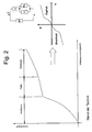
- FIGS. 1 and 2 each contain a replacement graph of any vibration and the achievable damping force characteristics.
- a volume flow Q divides into two flow paths.
- BP stands for bypass and takes into account all leaks between two work spaces, eg. B. on a piston ring or a piston rod guide. For consideration of the damping force characteristic, this proportion is negligible.
- In the parallel flow path there are usually three flow resistances or damping valve function elements.
- the reference symbol V is intended to designate a very small pre-opening cross-section, which produces a steep damping force characteristic even with very small volume flows Q.
- the Vorö Stammsquerites a spring-loaded valve element is connected in parallel, which often has a degressive or linear characteristic.
- the DE 197 12 895 A1 describes in particular in the synopsis of FIGS. 1 and 3 a damping valve with a flow direction-dependent Vorö Stammsventil.
- the pre-opening valve has a check valve disc whose Abhubweg is limited by a cover plate.
- the non-return valve disc rests on a valve disc and has at its inner diameter spring tongues, which are dimensioned such that the non-return valve disc lifts even at a very low flow velocity of the valve disc. With a larger flow velocity, the valve disc, the check valve disc and the cover plate lift off as a package from a piston.
- Object of the present invention is to provide a simple in construction damping valve having a free of damping force jumps opening behavior.
- the object is achieved in that the elastic valve disc has a throttle cross-section which acts in series with the passage, wherein the throttle cross-section is influenced by a second valve disc which rests on the side facing away from the Dämpfventilores the elastic valve disc and their Abhubterrorism of the valve support disc is limited, wherein the throttle cross-section is formed by a cut-free tongue portion of the elastic valve disc, which performs an independent of the Abhubiolo the elastic valve disc opening movement.
- the layered valve disks cooperate with a single valve seat surface on the damping valve body, so that manufacturing tolerances exert only a negligible influence on the opening behavior of the individual valve disks.
- the cut-free tongue region is embodied radially inside the valve seat surface of the damping valve body.
- the throttle area in the elastic valve disk can be chosen comparatively large, since there is no radial overlap with the valve seat surface and the throttle cross-section is covered by the second valve disk. Lateral outflow via the valve seat surface is excluded.
- a dependent claim is arranged axially between the elastic valve disc and the valve support disc at least one spacer whose height determines the maximum Abhubweg the second valve disc.
- the second valve disc can be designed to be elastic and deformed during the Abhubiolo of the elastic valve disc.
- the second valve disk can have at least one spring web which is issued from the plane of a cover surface and which can be supported on the valve support disk.
- the opening movement of the tongue portion is initiated by a smaller pressure force than the Abhubiolo the elastic valve disc of the valve seat surface of the Dämpfventil stressess.
- the at least one valve support disc can also be carried out elastically, the at least one valve support disc, so that all the valve disks involved are affected by the Abhubiolo from the valve body.
- the Fig. 3 shows a section of a vibration damper 1 with a cylinder 3, in which a piston rod 5 is guided axially movable. On the piston rod, a piston 7 is fixed, in which at least one passage channel 9; 11 is executed. The piston 7 separates a piston rod-side working space 13 from a piston rod remote working space 15, wherein both working spaces are filled with a damping medium.
- a rigid valve ring 17 closes the passageway 11, wherein the valve ring is biased by a valve spring 19 on the piston.
- the piston acts as Dämpfventilelasticity for the damping valve 11; 17; 19. This Dämpfventilbauform is well known and is intended to illustrate the difference from the invention.
- the passage 9 cooperates with a valve disc pack 21, which in the Fig. 4 is shown enlarged.
- the Dämpfventilmaschine 7 has an annular, closed valve seat surface 23, on which an elastic valve disc 25, called in the other first valve disc, is biased.
- the first valve disk 25 is centered, for example, on the piston rod 5 and is supported axially on the inside on a bearing ring 27. Between the valve seat surface and the outer diameter of the bearing ring 27, an annular space 28 is present.
- the special configuration of the first valve disc 25 can be seen, which like the Fig. 6 shows, a plurality of cut-tongue sections 29 has.
- the cutouts at the edges of the tongue regions form throttle cross sections 31, which are at least partially covered by a second valve disk 33, which rests on the first valve disk 25 on a side facing away from the damping valve body 7.
- the contours of the free cuts determine the size and thus the deformation behavior / the spring rate of the tongue areas 29. It can be provided that tongue areas of different size and shape are used in the first valve disc in order to realize an opening-following function of a plurality of tongue areas.
- the second valve disc is centered on one Spacer 35 having an axial distance to at least one valve support disc 37; 39 defined, which is preferably also elastic.
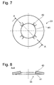
- the axial distance between the first valve disc 25 and the valve support disc 37 determines the Abhubweg the second valve disc, as a simple flapping disc or, like the FIGS. 7 and 8 show, may also be elastic and has at least one issued from the plane of a top surface 41 spring bar 43.
- valve disc pack 21 With the figure sequence 9 to 12, the opening behavior of the valve disc pack 21 is illustrated. At a small piston rod retraction speed prevails in the annular space 28 between the Dämpfventil stresses 7 and the bottom of the first valve disc 25 only a small pressure, so that the pressure force acting on the valve disc 25 moves neither a tongue portion 29 from the flatness, nor the whole valve disc of the valve seat 23 can lift off. Only the second valve disc 33 lifts off from the first valve disc 25 and releases the effective in series to Drosseikanal 9 throttle section 31 so that damping medium from the piston rod remote working chamber 15 can flow into the piston rod side working chamber 13 and thereby generates a low damping force.
- Fig. 10 is a next phase of the Abhubterrorism the valve disc pack 21 completed at a compared to Fig. 9 increased piston speed occurs.
- the second valve disk 33 has assumed its maximum passage position on the underside of the valve support disk 37, and the cut-out tongue portions 29 are elastically deformed from the flat position that the effective throttle cross-section 31 has increased in the first valve disc.
- the effective damping force is determined by the flow velocity and the size of the throttle cross sections.
- the annular outlet cross section 45 from the gap between the first valve disk 25 and the valve support disk 37 is so large that no Nachdrossel bine occur.
- the pressure force initiating the opening movement of the tongue regions 29 is smaller than the pressure force required for the lifting movement of the first valve disk 25 from the valve seat surface 23, wherein the maximum lift-off position is limited by the valve support disk 37.
- the first valve disk 25 Upon further increase in the piston speed or increase in the pressure acting on the first valve disk 25, the first valve disk 25 lifts according to Fig. 11 together with the second valve disc 33 from the valve seat surface until the valve disc 25 comes to rest on the underside of the valve support disc 37.
- the damping medium can pass directly between the valve seat surface 23 and the valve disc from the throttle channel 9 in the piston rod-side working space 13.
- the Fig. 12 shows the maximum Abhub ein the valve disc pack 21, wherein the first valve disc 25 together with the at least one valve support disc 37; 39 is elastically shielded and the outlet cross section 45 determines the damping force.
- the Figures 13 and 14 each show the replacement diagram of the damping valve according to the invention.
- An essential difference is that, apart from the leakage fractions BP, the entire volume flow Q has to flow through the passage channel and the throttling connected thereto and through a symbolic equivalent resistance FS.
- the pressure, the z. B. abuts the second valve disc 33 after the Abhubterrorism remains, even if a tongue 29 is deformed or the first valve disc is possibly deformed together with the valve support plates.
- the Vorö réellesquerites, the tongue and the valve discs 25 and 37; 39 are actuated by the volume flow in a compulsive sequence. There is no operating point or piston velocity that promotes fluttering of a valve disk. It can be seen from the kink-free transitions between the individual damping force characteristic curve sections that there is always a damping force curve that is free of damping force jumps.
- valve disk package according to the invention is not only usefully applicable to a Dämpfventil redesignseite, but also for both flow direction.
Landscapes
- Engineering & Computer Science (AREA)
- General Engineering & Computer Science (AREA)
- Mechanical Engineering (AREA)
- Fluid-Damping Devices (AREA)
- Lift Valve (AREA)
- Details Of Valves (AREA)
- Forging (AREA)
Abstract
Description
- Die Erfindung betrifft ein Dämpfventil gemäß dem Oberbegriff von Patentanspruch 1.
- Ein Dämpfventil besteht im einfachsten Fall aus einem Ventilkörper mit mindestens einem Durchgangskanal, der von einer Ventilscheibe in seinem wirksamen Durchlassquerschnitt beeinflusst wird. Die Ventilscheibe kann von einer Ventilfeder oder durch Eigenspannung in einer vorbestimmten Stellung gehalten werden. Ein grundsätzliches Problem besteht darin, dass bei einem derartigen Dämpfventil schon bei einer kleinen Öffnungsbewegung beim Durchlassquerschnitt ein deutlicher Zuwachs auftritt. Diese sprunghafte Änderung wirkt sich als Dämpfkraftsprung aus, der akustisch in Erscheinung tritt.
- Schon bei der
DE 29 09 278 A1 hat man dieses Problem erkannt und eine starre Ventilstützscheibe entwickelt, die parallele Biegekanten für eine elastische Ventilscheibe offenbart (Fig. 5 ). In einem ersten Dämpfmediumgeschwindigkeitsbereich kann das Dämpfmedium in dem Drosselkanal die elastische Ventilscheibe ab dem Bereich der Biegekante nach radial außen verformen, bis der Höhenversatz der Biegekante zu einer Abstützfläche ausgenutzt ist. Bei weiterem Druckanstieg hebt die Ventilstützscheibe zusammen mit der elastischen Ventilscheibe gegen eine zweite Ventilfeder ab. Durch diese Kombination mehrerer Feder und Ventilscheibenelemente kann ein vorteilhaftes Öffnungsverhalten erreicht werden. - Alternativ kann man, wie die
US 5 042 624 zeigt auch ein elastisches Ventilscheibenpaket in Kombination mit zwei unabhängigen Ventilsitzflächen für zwei Ventilscheibengruppen verwenden. Der Nachteil dieser Lösung besteht jedoch darin, dass sich die Vielzahl der Toleranzen der Ventilscheibenmaterialstärken und die axialen Versatzmaße der Ventilsitzflächen negativ auf die Einhaltung der Vorspannkräfte der Ventilscheiben auswirken. - Die
Figuren 1 und2 enthalten jeweils ein Ersatzschaubild eines beliebigen Schwingungsdämpfers und die damit erreichbaren Dämpfkraftkennlinien. Ein Volumenstrom Q teilt sich in zwei Strömungswege. BP steht für Bypass und berücksichtigt alle Leckagen zwischen zwei Arbeitsräumen, z. B. an einem Kolbenring oder einer Kolbenstangenführung. Für die Betrachtung der Dämpfkraftkennlinie ist dieser Anteil zu vernachlässigen. In dem parallelen Strömungsweg sind in der Regel drei Strömungswiderstände oder Dämpfventilfunktionselemente vorhanden. Mit dem Bezugszeichen V soll ein sehr kleiner Voröffnungsquerschnitt benannt sein, der schon bei sehr kleinen Volumenströmen Q eine steile Dämpfkraftkennlinie erzeugt. Dem Voröffnungsquerschnitt ist ein federkraftbelastetes Ventilelement parallel geschaltet, das häufig eine degressive oder lineare Kennlinie aufweist. Bei maximal geöffnetem Ventilelement Fe wirkt sich eine Drosselung in einem Durchlasskanal zwischen zwei Arbeitsräumen aus, wodurch bei sehr hohen Kolbengeschwindigkeiten eine stark progressive Dämpfkraftkennlinie erzeugt wird. In derFig. 1 sind verschiedene Kennlinien von verschiedenen Voröffnungsgrößen dargestellt. Allen gemeinsam ist der ausgeprägt progressive Kennlinienverlauf. In derFig. 2 ist die aus Voröffnungsquerschnitt, federbelastetem Ventilelement und Drosselung überlagerte Dämpfkraftkennlinie mit den jeweiligen Wirkungsabschnitten dargestellt. Aus der Zusammenschau derFig. 1 und2 ist ersichtlich, dass unabhängig von der Größe der Voröffnung ein scharfer Kennlinienknick entsteht, der für die Geräuschbildung im Dämpfventil verantwortlicht ist. An dem Kennlinienknick setzt die Öffnungsbewegung des federkraftbelasteten Ventilelements ein. Bei einer Kolbengeschwindigkeit V1 oder V2 oder V3 findet eine undefinierte Öffnungs- und Schließbewegung des federkraftbelasteten Ventilelements statt, die als Flattern ein Geräusch verursacht. - Die
DE 197 12 895 A1 beschreibt insbesondere in der Zusammenschau derFiguren 1 und3 ein Dämpfventil mit einem strömungsrichtungsabhängigen Voröffnungsventil. Das Voröffnungsventil verfügt über eine Rückschlagventilscheibe, deren Abhubweg von einer Deckscheibe begrenzt wird. Die Rückschlagventilscheibe liegt auf einer Ventilscheibe auf und weist an ihrem Innendurchmesser Federzungen auf, die derart bemessen sind, dass die Rückschlagventilscheibe schon bei einer sehr geringen Anströmungsgeschwindigkeit von der Ventilscheibe abhebt. Bei einer größeren Anströmgeschwindigkeit heben die Ventilscheibe, die Rückschlagventilscheibe und die Deckscheibe als Paket von einem Kolben ab. - Aufgabe der vorliegenden Erfindung ist es, ein im Aufbau einfaches Dämpfventil zu schaffen, das ein von Dämpfkraftsprüngen freies Öffnungsverhalten aufweist.
- Erfindungsgemäß wird die Aufgabe dadurch gelöst, dass die elastische Ventilscheibe einen Drosselquerschnitt aufweist, der in Reihe zu dem Durchlasskanal wirkt, wobei der Drosselquerschnitt von einer zweiten Ventilscheibe beeinflusst wird, die auf der dem Dämpfventilkörper abgewandten Seite der elastischen Ventilscheibe aufliegt und deren Abhubbewegung von der Ventilstützscheibe begrenzt wird, wobei der Drosselquerschnitt von einem freigeschnittenen Zungenbereich der elastischen Ventilscheibe gebildet wird, der eine von der Abhubbewegung der elastischen Ventilscheibe unabhängige Öffnungsbewegung ausführt.
- Die geschichteten Ventilscheiben wirken mit einer einzigen Ventilsitzfläche am Dämpfventilkörper zusammen, so dass Fertigungstoleranzen nur einen vernachlässigbaren Einfluss auf das Öffnungsverhalten der einzelnen Ventilscheiben ausüben. Insgesamt liegt eine kompakte Bauform vor, die vielfältige Möglichkeiten zur Anpassung der Dämpfventilkräfte bietet, so dass ein sprunghafter Dämpfkraftanstieg bei der Abhubbewegung ausgehend von einer maximal geschlossenen Ventilscheibenstellung bis zu einer maximal geöffneten Ventilscheibenstellung auftritt.
- In weiterer vorteilhafter Ausgestaltung ist der freigeschnittene Zungenbereich radial innerhalb der Ventilsitzfläche des Dämpfventitkörpers ausgeführt. Der Drosselbereich in der elastischen Ventilscheibe kann vergleichsweise groß gewählt werden, da keine radiale Überdeckung mit der Ventilsitzfläche besteht und der Drosselquerschnitt von der zweiten Ventilscheibe abgedeckt wird. Ein seitlicher Abfluss über die Ventilsitzfläche ist ausgeschlossen.
- Gemäß einem Unteranspruch ist axial zwischen der elastischen Ventilscheibe und der Ventilstützscheibe mindestens eine Distanzscheibe angeordnet, deren Bauhöhe den maximalen Abhubweg der zweiten Ventilscheibe bestimmt. Durch die Wahl der Distanzscheibenhöhe kann das Öffnungsverhalten des gesamten Ventilscheibenpakets beeinflusst werden.
- Auch die zweite Ventilscheibe kann elastisch ausgeführt sein und bei der Abhubbewegung von der elastischen Ventilscheibe verformt werden.
- Die zweite Ventilscheibe kann mindestens einen aus der Ebene einer Deckfläche ausgestellten Federsteg aufweisen, der sich an der Ventilstützscheibe abstützen kann.
- Für eine optimale Ventilscheibenabhubbewegung ist vorgesehen, dass die zum Abhub der zweiten Ventilscheibe von der ersten Ventilscheibe notwendige Druckkraft kleiner ist als die Druckkraft zum Abhub der elastischen Ventilscheibe von der Ventilsitzfläche des Dämpfventilkörpers.
- Vorteilhafterweise wird die Öffnungsbewegung des Zungenbereichs von einer kleineren Druckkraft initiiert als die Abhubbewegung der elastischen Ventilscheibe von der Ventilsitzfläche des Dämpfventilkörpers.
- Es kann auch die mindestens eine Ventilstützscheibe elastisch ausgeführt sein, so dass alle beteiligten Ventilscheiben an der Abhubbewegung vom Ventilkörper betroffen sind.
- Anhand der folgenden Figurenbeschreibung soll die Erfindung näher erläutert werden.
- Es zeigt:
- Fig.1
- Ersatzschaubild und Dämpfkraftkennlinie eines konventionellen Dämpfventils
- Fig. 2
- Dämpfkraftkennlinie nach
Fig. 1 mit den jeweils wirksamen Ventilelementen - Fig. 3
- Dämpfventil im Kolben eines Schwingungsdämpfers
- Fig. 4
- Vergrößerte Darstellung des Ventilpakets vom Dämpfventil
- Fig. 5
- Elastische Ventilscheibe in der Draufsicht
- Fig. 6
- Ausschnittvergrößerung zur
Fig. 5 - Fig. 7
- Draufsicht zur zweiten Ventilscheibe
- Fig. 8
- Schnittdarstellung zur
Fig. 7 - Fig. 9-12
- Darstellung der Ventilabhubbewegung
- Fig.13
- Ersatzschaubild und Dämpfkraftkennlinie des erfindungsgemäßen Dämpfventils
- Fig. 14
- Überlagerte Dämpfkraftkennlinie
- Die
Fig. 3 zeigt einen Ausschnitt aus einem Schwingungsdämpfer 1 mit einem Zylinder 3, in dem eine Kolbenstange 5 axial beweglich geführt ist. An der Kolbenstange ist ein Kolben 7 befestigt, in dem mindestens ein Durchlasskanal 9; 11 ausgeführt ist. Der Kolben 7 trennt einen kolbenstangenseitigen Arbeitsraum 13 von einem kolbenstangenfernen Arbeitsraum 15, wobei beide Arbeitsräume mit einem Dämpfmedium gefüllt sind. - An einem Austrittsende im kolbenstangenfernen Arbeitsraum 15 verschließt ein starrer Ventilring 17 den Durchlasskanal 11, wobei der Ventilring von einer Ventilfeder 19 auf den Kolben vorgespannt wird. Der Kolben fungiert als Dämpfventilkörper für das Dämpfventil 11; 17; 19. Diese Dämpfventilbauform ist allgemein bekannt und soll den Unterschied zur Erfindung verdeutlichen.
- Der Durchlasskanal 9 wirkt mit einem Ventilscheibenpaket 21 zusammen, das in der
Fig. 4 vergrößert dargestellt ist. Der Dämpfventilkörper 7 verfügt über eine kreisringförmige, geschlossene Ventilsitzfläche 23, auf der eine elastische Ventilscheibe 25, im weiteren erste Ventilscheibe genannt, vorgespannt ist. Die erste Ventilscheibe 25 zentriert sich beispielsweise an der Kolbenstange 5 und stützt sich axial innenseitig auf einem Lagerring 27 ab. Zwischen der Ventilsitzfläche und dem Außendurchmesser des Lagerrings 27 liegt ein Ringraum 28 vor. - Aus der
Fig. 5 ist die besondere Ausgestaltung der ersten Ventilscheibe 25 erkennbar, die wie dieFig. 6 zeigt, eine Mehrzahl von freigeschnittenen Zungenbereichen 29 aufweist. Die Freischnitte an den Rändern der Zungenbereiche bilden Drosselquerschnitte 31, die von einer zweiten Ventilscheibe 33, die auf einer dem Dämpfventilkörper 7 abgewandten Seite auf der ersten Ventilscheibe 25 aufliegt, zumindest teilweise abgedeckt werden. Die Konturen der Freischnitte bestimmen die Größe und damit das Umformverhalten/die Federrate der Zungenbereiche 29. Man kann vorsehen, dass in der ersten Ventilscheibe Zungenbereiche unterschiedlicher Größe und Form verwendet werden, um eine Öffnungs-Folgefunktion von mehreren Zungenbereichen zu verwirklichen. Die zweite Ventilscheibe zentriert sich an einer Distanzscheibe 35, die einen axialen Abstand zu mindestens einer Ventilstützscheibe 37; 39 definiert, die bevorzugt ebenfalls elastisch ist. - Der axiale Abstand zwischen der ersten Ventilscheibe 25 und der Ventilstützscheibe 37 bestimmt den Abhubweg der zweiten Ventilscheibe, die als einfache Flatterscheibe oder, wie die
Figuren 7 und 8 zeigen, auch elastisch ausgeführt sein kann und mindestens einen aus der Ebene einer Deckfläche 41 ausgestellten Federsteg 43 aufweist. - Mit der Figurenfolge 9 bis 12 wird das Öffnungsverhalten des Ventilscheibenpakets 21 verdeutlicht. Bei einer kleinen Kolbenstangeneinfahrgeschwindigkeit herrscht in dem Ringraum 28 zwischen dem Dämpfventilkörper 7 und der Unterseite der ersten Ventilscheibe 25 nur ein kleiner Druck, so dass die Druckkraft, die auf die Ventilscheibe 25 wirkt weder einen Zungenbereich 29 aus der Planlage bewegt, noch die ganze Ventilscheibe von der Ventilsitzfläche 23 abheben lässt. Lediglich die zweite Ventilscheibe 33 hebt von der ersten Ventilscheibe 25 ab und gibt den in Reihe zum Drosseikanal 9 wirksamen Drosselquerschnitt 31 frei, so dass Dämpfmedium aus dem kolbenstangenfernen Arbeitsraum 15 in den kolbenstangenseitigen Arbeitsraum 13 strömen kann und dabei eine geringe Dämpfkraft erzeugt.
- In der
Fig. 10 ist eine nächste Phase der Abhubbewegung des Ventilscheibenpakets 21 abgeschlossen, die bei einer im Vergleich zurFig. 9 erhöhten Kolbengeschwindigkeit auftritt. Die zweite Ventilscheibe 33 hat an der Unterseite der Ventilstützscheibe 37 ihre maximale Durchlassposition eingenommen und die freigeschnittenen Zungenbereiche 29 sind aus der Planlage elastisch verformt, so dass der wirksame Drosselquerschnitt 31 in der ersten Ventilscheibe zugenommen hat. Die wirksame Dämpfkraft wird von der Strömungsgeschwindigkeit und der Größe der Drosselquerschnitte bestimmt. Der ringförmige Austrittsquerschnitt 45 aus dem Spalt zwischen der ersten Ventilscheibe 25 und der Ventilstützscheibe 37 ist so groß, dass keine Nachdrosseleffekte auftreten. Die die Öffnungsbewegung der Zungenbereiche 29 initiierende Druckkraft ist kleiner als die für die Abhubbewegung der ersten Ventilscheibe 25 von der Ventilsitzfläche 23 notwendige Druckkraft, wobei die maximale Abhubposition von der Ventilstützscheibe 37 begrenzt wird. - Bei weiterer Steigerung der Kolbengeschwindigkeit bzw. Erhöhung der auf die erste Ventilscheibe 25 wirksamen Druckkraft hebt die erste Ventilscheibe 25 gemäß
Fig. 11 zusammen mit der zweiten Ventilscheibe 33 von der Ventilsitzfläche ab, bis die Ventilscheibe 25 an der Unterseite der Ventilstützscheibe 37 zur Anlage kommt. Dabei kann das Dämpfmedium direkt zwischen der Ventilsitzfläche 23 und der Ventilscheibe aus dem Drosselkanal 9 in den kolbenstangenseitigen Arbeitsraum 13 übertreten. - Die
Fig. 12 zeigt die maximale Abhubstellung des Ventilscheibenpakets 21, bei der die erste Ventilscheibe 25 zusammen mit der mindestens einen Ventilstützscheibe 37; 39 elastisch geschirmt wird und der Austrittsquerschnitt 45 die Dämpfkraft bestimmt. - Ein Schwingungsdämpfer führt eine oszillierende Bewegung mit ständig sich ändernder Hubgeschwindigkeit aus. Bei jeder Bewegungsrichtungsänderung wird der Zustand v = 0 durchfahren, so dass dann das Abhubverhalten nach
Fig. 9 abläuft und sich in Abhängigkeit der weiteren Hubgeschwindigkeit des Kolbens die Phasen nach denFig. 10 bis 12 anschließen können, womit eine kontinuierliche Vergrößerung der Drosselquerschnitte und damit Dämpfkräfte verbunden ist. - Die
Figuren 13 und14 zeigen jeweils das Ersatzschaubild des erfindungsgemäßen Dämpfventils. Ein wesentlicher Unterschied besteht darin, dass, abgesehen von den Leckagenanteilen BP, der gesamte Volumenstrom Q durch den Durchlasskanal und die damit verbundene Drosselung und durch einen symbolischen Ersatzwiderstand FS fließen muss. Der Druck, der z. B. an der zweiten Ventilscheibe 33 nach deren Abhubbewegung anliegt, bleibt beibehalten, auch wenn sich eine Zunge 29 verformt oder die erste Ventilscheibe ggf. zusammen mit den Ventilstützscheiben verformt wird. Der Voröffnungsquerschnitt, die Zunge und die Ventilscheiben 25 und 37; 39 werden vom Volumenstrom in einer zwanghaften Reihenfolge betätigt. Es gibt keinen Betriebspunkt bzw. keine Kolbengeschwindigkeit die eine Flatterneigung einer Ventilscheibe fördert. An den knickfreien Übergängen zwischen den einzelnen Dämpfkraftkennlinienabschnitten ist erkennbar, dass stets ein von Dämpfkraftsprüngen freier Dämpfkraftverlauf vorliegt. - Das erfindungsgemäße Ventilscheibenpaket ist nicht nur sinnvollerweise auf einer Dämpfventilkörperseite, sondern auch für beide Strömungsrichtung anwendbar.
Claims (8)
- Dämpfventil mit einem Dämpfventilkörper, der mindestens einen Durchlasskanal aufweist, dessen Querschnitt von mindestens einer elastischen Ventilscheibe auf einer Ventilsitzfläche des Dämpfventilkörpers beeinflusst wird, wobei die elastische Ventilscheibe ab einem definierten Abhubweg an einer Ventilstützscheibe zur Anlage kommt,
dadurch gekennzeichnet,
dass die elastische Ventilscheibe (25) einen Drosselquerschnitt (31) aufweist, der in Reihe zu dem Durchlasskanal (9) wirkt, wobei der Drosselquerschnitt (31) von einer zweiten Ventilscheibe (33) beeinflusst wird, die auf der dem Dämpfventilkörper (7) abgewandten Seite der elastischen Ventilscheibe (25) aufliegt und deren Abhubbewegung von der Ventilstützscheibe (37) begrenzt wird, wobei der Drosselquerschnitt (31) von einem freigeschnittenen Zungenbereich (29) der elastischen Ventilscheibe (25) gebildet wird, der eine von der Abhubbewegung der elastischen Ventilscheibe (25) unabhängige Öffnungsbewegung ausführt. - Dämpfventil nach Anspruch 1,
dadurch gekennzeichnet,
dass der freigeschnittene Zungenbereich (29) radial innerhalb der Ventilsitzfläche (23) des Dämpfventilkörpers (23) ausgeführt ist. - Dämpfventil nach Anspruch 1,
dadurch gekennzeichnet,
dass axial zwischen der elastischen Ventilscheibe (25) und der Ventilstützscheibe (37) mindestens eine Distanzscheibe (35) angeordnet ist, deren Bauhöhe den maximalen Abhubweg der zweiten Ventilscheibe (33) bestimmt. - Dämptventil nach Anspruch 1,
dadurch gekennzeichnet,
dass die zweite Ventilscheibe (33) elastisch ausgeführt ist und bei der Abhubbewegung von der elastischen Ventilscheibe (25) verformt wird. - Dämpfventil nach Anspruch 4,
dadurch gekennzeichnet,
dass die zweite Ventilscheibe (33) mindestens einen aus der Ebene einer Deckfläche (41) ausgestellten Federsteg (43) aufweist. - Dämpfventil nach Anspruch 1,
dadurch gekennzeichnet,
dass die zum Abhub der zweiten Ventilscheibe (33) von der ersten Ventilscheibe (25) notwendige Druckkraft kleiner ist als die Druckkraft zum Abhub der elastischen Ventilscheibe (25) von der Ventilsitzfläche (23) des Dämpfventilkörpers (7). - Dämpfventil nach Anspruch 1,
dadurch gekennzeichnet,
dass die Öffnungsbewegung des Zungenbereichs (29) von einer kleineren Druckkraft initiiert wird als die Abhubbewegung der elastischen Ventilscheibe (25) von der Ventilsitzfläche (23) des Dämpfventilkörpers (7). - Dämpfventil nach Anspruch 1,
dadurch gekennzeichnet,
dass die mindestens eine Ventilstützscheibe (37; 39) elastisch ausgeführt ist.
Applications Claiming Priority (1)
| Application Number | Priority Date | Filing Date | Title |
|---|---|---|---|
| DE102007007722A DE102007007722B3 (de) | 2007-02-16 | 2007-02-16 | Dämpfventil mit optimierter Ventilöffnungsfunktion |
Publications (2)
| Publication Number | Publication Date |
|---|---|
| EP1959154A1 true EP1959154A1 (de) | 2008-08-20 |
| EP1959154B1 EP1959154B1 (de) | 2009-12-30 |
Family
ID=39284142
Family Applications (1)
| Application Number | Title | Priority Date | Filing Date |
|---|---|---|---|
| EP08002088A Not-in-force EP1959154B1 (de) | 2007-02-16 | 2008-02-05 | Dämpfventil mit optimierter Ventilöffnungsfunktion |
Country Status (3)
| Country | Link |
|---|---|
| EP (1) | EP1959154B1 (de) |
| AT (1) | ATE453817T1 (de) |
| DE (2) | DE102007007722B3 (de) |
Cited By (3)
| Publication number | Priority date | Publication date | Assignee | Title |
|---|---|---|---|---|
| GB2461892A (en) * | 2008-07-16 | 2010-01-20 | Univ Sheffield | A damper for a mountain bike |
| JP2010112464A (ja) * | 2008-11-06 | 2010-05-20 | Kayaba Ind Co Ltd | リーフバルブ |
| DE102014225702A1 (de) * | 2014-12-12 | 2016-06-16 | Zf Friedrichshafen Ag | Verstellbare Dämpfventileinrichtung |
Families Citing this family (7)
| Publication number | Priority date | Publication date | Assignee | Title |
|---|---|---|---|---|
| FR2959289B1 (fr) * | 2010-04-26 | 2012-05-25 | Peugeot Citroen Automobiles Sa | Dispositif d'amortissement, en particulier pour suspension de vehicule automobile |
| DE102016213328B4 (de) | 2016-07-21 | 2020-06-18 | Zf Friedrichshafen Ag | Dämpfventil mit richtungsabhängigem Voröffnungsquerschnitt für einen Schwingungsdämpfer |
| DE102016218375A1 (de) * | 2016-09-23 | 2018-03-29 | Zf Friedrichshafen Ag | Dämpfventil für einen Schwingungsdämpfer |
| DE102016218376A1 (de) * | 2016-09-23 | 2018-03-29 | Zf Friedrichshafen Ag | Dämpfventil für einen Schwingungsdämpfer |
| DE102016218371A1 (de) * | 2016-09-23 | 2018-03-29 | Zf Friedrichshafen Ag | Dämpfventil für einen Schwingungsdämpfer |
| DE102016218373A1 (de) | 2016-09-23 | 2018-03-29 | Zf Friedrichshafen Ag | Dämpfventil für einen Schwingungsdämpfer |
| DE102018116557A1 (de) * | 2018-07-09 | 2020-01-09 | Thyssenkrupp Ag | Schwingungsdämpfer, Kolben und Verfahren zur Einstellung der Dämpfung |
Citations (4)
| Publication number | Priority date | Publication date | Assignee | Title |
|---|---|---|---|---|
| DE2909278A1 (de) | 1978-03-14 | 1979-09-27 | Iao Industrie Riunite Spa | Hydraulischer stossdaempfer |
| JPH03168430A (ja) * | 1989-11-28 | 1991-07-22 | Kayaba Ind Co Ltd | 油圧緩衝器のバルブ装置 |
| US5042624A (en) | 1988-09-29 | 1991-08-27 | Atsugi Unisia Corporation | Hydraulic shock absorber with pre-loaded valve for linear variation characteristics of damping force |
| DE19712895A1 (de) | 1997-03-27 | 1998-10-08 | Mannesmann Sachs Ag | Schwingungsdämpfer mit richtungsabhängigem Voröffnungsquerschnitt |
Family Cites Families (3)
| Publication number | Priority date | Publication date | Assignee | Title |
|---|---|---|---|---|
| JP2839252B2 (ja) * | 1987-11-19 | 1998-12-16 | 株式会社ユニシアジェックス | 液圧緩衝器 |
| DE4025115C2 (de) * | 1990-08-08 | 2002-11-28 | Zf Sachs Ag | Kurzbauendes Dämpfventil |
| US5325942A (en) * | 1991-03-14 | 1994-07-05 | Monroe Auto Equipment Company | Tunable hydraulic valve for shock absorber |
-
2007
- 2007-02-16 DE DE102007007722A patent/DE102007007722B3/de not_active Expired - Fee Related
-
2008
- 2008-02-05 EP EP08002088A patent/EP1959154B1/de not_active Not-in-force
- 2008-02-05 DE DE502008000271T patent/DE502008000271D1/de active Active
- 2008-02-05 AT AT08002088T patent/ATE453817T1/de active
Patent Citations (4)
| Publication number | Priority date | Publication date | Assignee | Title |
|---|---|---|---|---|
| DE2909278A1 (de) | 1978-03-14 | 1979-09-27 | Iao Industrie Riunite Spa | Hydraulischer stossdaempfer |
| US5042624A (en) | 1988-09-29 | 1991-08-27 | Atsugi Unisia Corporation | Hydraulic shock absorber with pre-loaded valve for linear variation characteristics of damping force |
| JPH03168430A (ja) * | 1989-11-28 | 1991-07-22 | Kayaba Ind Co Ltd | 油圧緩衝器のバルブ装置 |
| DE19712895A1 (de) | 1997-03-27 | 1998-10-08 | Mannesmann Sachs Ag | Schwingungsdämpfer mit richtungsabhängigem Voröffnungsquerschnitt |
Cited By (4)
| Publication number | Priority date | Publication date | Assignee | Title |
|---|---|---|---|---|
| GB2461892A (en) * | 2008-07-16 | 2010-01-20 | Univ Sheffield | A damper for a mountain bike |
| JP2010112464A (ja) * | 2008-11-06 | 2010-05-20 | Kayaba Ind Co Ltd | リーフバルブ |
| DE102014225702A1 (de) * | 2014-12-12 | 2016-06-16 | Zf Friedrichshafen Ag | Verstellbare Dämpfventileinrichtung |
| US10400849B2 (en) | 2014-12-12 | 2019-09-03 | Zf Friedrichshafen Ag | Adjustable damping valve device |
Also Published As
| Publication number | Publication date |
|---|---|
| DE502008000271D1 (de) | 2010-02-11 |
| ATE453817T1 (de) | 2010-01-15 |
| DE102007007722B3 (de) | 2008-06-19 |
| EP1959154B1 (de) | 2009-12-30 |
Similar Documents
| Publication | Publication Date | Title |
|---|---|---|
| EP1959154B1 (de) | Dämpfventil mit optimierter Ventilöffnungsfunktion | |
| EP3212958B1 (de) | Verfahren zum betreiben eines regelbaren schwingungsdämpfers für kraftfahrzeuge | |
| DE102005046276B3 (de) | Dämpfventileinrichtung mit progressivem Dämpfkraftverlauf | |
| DE102016000098B4 (de) | Schwingungsdämpfer vom Typ mit variabler Dämpfungskraft | |
| DE112017004850T5 (de) | Stoßdämpfer | |
| DE202012103981U1 (de) | Dämpfungsventil für einen Stoßdämpfer | |
| DE10351357B3 (de) | Dämpfventil mit richtungsabhängig schaltbaren Querschnitt | |
| DE2547322A1 (de) | Hydraulischer stossdaempfer | |
| DE112016004164B4 (de) | Stoßdämpfer | |
| DE102019215561A1 (de) | Drosselstelle für einen Schwingungsdämpfer | |
| DE112020003042T5 (de) | Stossdämpfer | |
| WO2015185279A1 (de) | Frequenzabhängige dämpfventilanordnung | |
| DE112020005357T5 (de) | Stossdämpfer | |
| DE112019006507T5 (de) | Stoßdämpfer | |
| EP2045484A2 (de) | Dämpfventil | |
| EP3464933B1 (de) | Frequenzselektiver schwingungsdämpfer für kraftfahrzeuge mit einem bypasssteuerventil | |
| DE102016217112A1 (de) | Frequenzabhängige Dämpfventilanordnung | |
| EP1087153A1 (de) | Vorrichtung zur Erhöhung der Dämpfung | |
| EP2327903A2 (de) | Dämpfventileinrichtung mit einer mehrstufigen Dämpfkraftkennlinie | |
| EP1879668B1 (de) | Explosionsschutzventil | |
| DE19615587C2 (de) | Schwingungsdämpfer mit richtungsabhängigem Voröffnungsquerschnitt | |
| DE102022204125A1 (de) | Verstellbare Dämpfventileinrichtung | |
| DE10124582C1 (de) | Dämpfventil | |
| DE102020209101A1 (de) | Drosselstelle mit einem sich im Durchmesser ändernden Ventilkörper | |
| EP2196696A2 (de) | Schwingungsdämpfer |
Legal Events
| Date | Code | Title | Description |
|---|---|---|---|
| PUAI | Public reference made under article 153(3) epc to a published international application that has entered the european phase |
Free format text: ORIGINAL CODE: 0009012 |
|
| 17P | Request for examination filed |
Effective date: 20080509 |
|
| AK | Designated contracting states |
Kind code of ref document: A1 Designated state(s): AT BE BG CH CY CZ DE DK EE ES FI FR GB GR HR HU IE IS IT LI LT LU LV MC MT NL NO PL PT RO SE SI SK TR |
|
| AX | Request for extension of the european patent |
Extension state: AL BA MK RS |
|
| AKX | Designation fees paid |
Designated state(s): AT BE BG CH CY CZ DE DK EE ES FI FR GB GR HR HU IE IS IT LI LT LU LV MC MT NL NO PL PT RO SE SI SK TR |
|
| GRAP | Despatch of communication of intention to grant a patent |
Free format text: ORIGINAL CODE: EPIDOSNIGR1 |
|
| GRAS | Grant fee paid |
Free format text: ORIGINAL CODE: EPIDOSNIGR3 |
|
| GRAA | (expected) grant |
Free format text: ORIGINAL CODE: 0009210 |
|
| AK | Designated contracting states |
Kind code of ref document: B1 Designated state(s): AT BE BG CH CY CZ DE DK EE ES FI FR GB GR HR HU IE IS IT LI LT LU LV MC MT NL NO PL PT RO SE SI SK TR |
|
| REG | Reference to a national code |
Ref country code: GB Ref legal event code: FG4D Free format text: NOT ENGLISH |
|
| REG | Reference to a national code |
Ref country code: CH Ref legal event code: EP |
|
| REG | Reference to a national code |
Ref country code: IE Ref legal event code: FG4D |
|
| REF | Corresponds to: |
Ref document number: 502008000271 Country of ref document: DE Date of ref document: 20100211 Kind code of ref document: P |
|
| PG25 | Lapsed in a contracting state [announced via postgrant information from national office to epo] |
Ref country code: SE Free format text: LAPSE BECAUSE OF FAILURE TO SUBMIT A TRANSLATION OF THE DESCRIPTION OR TO PAY THE FEE WITHIN THE PRESCRIBED TIME-LIMIT Effective date: 20091230 Ref country code: LT Free format text: LAPSE BECAUSE OF FAILURE TO SUBMIT A TRANSLATION OF THE DESCRIPTION OR TO PAY THE FEE WITHIN THE PRESCRIBED TIME-LIMIT Effective date: 20091230 Ref country code: NO Free format text: LAPSE BECAUSE OF FAILURE TO SUBMIT A TRANSLATION OF THE DESCRIPTION OR TO PAY THE FEE WITHIN THE PRESCRIBED TIME-LIMIT Effective date: 20100330 Ref country code: FI Free format text: LAPSE BECAUSE OF FAILURE TO SUBMIT A TRANSLATION OF THE DESCRIPTION OR TO PAY THE FEE WITHIN THE PRESCRIBED TIME-LIMIT Effective date: 20091230 |
|
| REG | Reference to a national code |
Ref country code: NL Ref legal event code: VDEP Effective date: 20091230 |
|
| LTIE | Lt: invalidation of european patent or patent extension |
Effective date: 20091230 |
|
| PG25 | Lapsed in a contracting state [announced via postgrant information from national office to epo] |
Ref country code: SI Free format text: LAPSE BECAUSE OF FAILURE TO SUBMIT A TRANSLATION OF THE DESCRIPTION OR TO PAY THE FEE WITHIN THE PRESCRIBED TIME-LIMIT Effective date: 20091230 Ref country code: PL Free format text: LAPSE BECAUSE OF FAILURE TO SUBMIT A TRANSLATION OF THE DESCRIPTION OR TO PAY THE FEE WITHIN THE PRESCRIBED TIME-LIMIT Effective date: 20091230 Ref country code: LV Free format text: LAPSE BECAUSE OF FAILURE TO SUBMIT A TRANSLATION OF THE DESCRIPTION OR TO PAY THE FEE WITHIN THE PRESCRIBED TIME-LIMIT Effective date: 20091230 Ref country code: HR Free format text: LAPSE BECAUSE OF FAILURE TO SUBMIT A TRANSLATION OF THE DESCRIPTION OR TO PAY THE FEE WITHIN THE PRESCRIBED TIME-LIMIT Effective date: 20091230 |
|
| REG | Reference to a national code |
Ref country code: IE Ref legal event code: FD4D |
|
| PG25 | Lapsed in a contracting state [announced via postgrant information from national office to epo] |
Ref country code: EE Free format text: LAPSE BECAUSE OF FAILURE TO SUBMIT A TRANSLATION OF THE DESCRIPTION OR TO PAY THE FEE WITHIN THE PRESCRIBED TIME-LIMIT Effective date: 20091230 Ref country code: BG Free format text: LAPSE BECAUSE OF FAILURE TO SUBMIT A TRANSLATION OF THE DESCRIPTION OR TO PAY THE FEE WITHIN THE PRESCRIBED TIME-LIMIT Effective date: 20100330 Ref country code: RO Free format text: LAPSE BECAUSE OF FAILURE TO SUBMIT A TRANSLATION OF THE DESCRIPTION OR TO PAY THE FEE WITHIN THE PRESCRIBED TIME-LIMIT Effective date: 20091230 Ref country code: IS Free format text: LAPSE BECAUSE OF FAILURE TO SUBMIT A TRANSLATION OF THE DESCRIPTION OR TO PAY THE FEE WITHIN THE PRESCRIBED TIME-LIMIT Effective date: 20100430 Ref country code: NL Free format text: LAPSE BECAUSE OF FAILURE TO SUBMIT A TRANSLATION OF THE DESCRIPTION OR TO PAY THE FEE WITHIN THE PRESCRIBED TIME-LIMIT Effective date: 20091230 Ref country code: ES Free format text: LAPSE BECAUSE OF FAILURE TO SUBMIT A TRANSLATION OF THE DESCRIPTION OR TO PAY THE FEE WITHIN THE PRESCRIBED TIME-LIMIT Effective date: 20100410 |
|
| BERE | Be: lapsed |
Owner name: ZF FRIEDRICHSHAFEN A.G. Effective date: 20100228 |
|
| PG25 | Lapsed in a contracting state [announced via postgrant information from national office to epo] |
Ref country code: SK Free format text: LAPSE BECAUSE OF FAILURE TO SUBMIT A TRANSLATION OF THE DESCRIPTION OR TO PAY THE FEE WITHIN THE PRESCRIBED TIME-LIMIT Effective date: 20091230 Ref country code: CZ Free format text: LAPSE BECAUSE OF FAILURE TO SUBMIT A TRANSLATION OF THE DESCRIPTION OR TO PAY THE FEE WITHIN THE PRESCRIBED TIME-LIMIT Effective date: 20091230 |
|
| PG25 | Lapsed in a contracting state [announced via postgrant information from national office to epo] |
Ref country code: MC Free format text: LAPSE BECAUSE OF NON-PAYMENT OF DUE FEES Effective date: 20100301 Ref country code: IE Free format text: LAPSE BECAUSE OF FAILURE TO SUBMIT A TRANSLATION OF THE DESCRIPTION OR TO PAY THE FEE WITHIN THE PRESCRIBED TIME-LIMIT Effective date: 20091230 Ref country code: CY Free format text: LAPSE BECAUSE OF FAILURE TO SUBMIT A TRANSLATION OF THE DESCRIPTION OR TO PAY THE FEE WITHIN THE PRESCRIBED TIME-LIMIT Effective date: 20091230 Ref country code: GR Free format text: LAPSE BECAUSE OF FAILURE TO SUBMIT A TRANSLATION OF THE DESCRIPTION OR TO PAY THE FEE WITHIN THE PRESCRIBED TIME-LIMIT Effective date: 20100331 |
|
| PLBE | No opposition filed within time limit |
Free format text: ORIGINAL CODE: 0009261 |
|
| STAA | Information on the status of an ep patent application or granted ep patent |
Free format text: STATUS: NO OPPOSITION FILED WITHIN TIME LIMIT |
|
| 26N | No opposition filed |
Effective date: 20101001 |
|
| PG25 | Lapsed in a contracting state [announced via postgrant information from national office to epo] |
Ref country code: DK Free format text: LAPSE BECAUSE OF FAILURE TO SUBMIT A TRANSLATION OF THE DESCRIPTION OR TO PAY THE FEE WITHIN THE PRESCRIBED TIME-LIMIT Effective date: 20091230 |
|
| PG25 | Lapsed in a contracting state [announced via postgrant information from national office to epo] |
Ref country code: BE Free format text: LAPSE BECAUSE OF NON-PAYMENT OF DUE FEES Effective date: 20100228 |
|
| PG25 | Lapsed in a contracting state [announced via postgrant information from national office to epo] |
Ref country code: IT Free format text: LAPSE BECAUSE OF FAILURE TO SUBMIT A TRANSLATION OF THE DESCRIPTION OR TO PAY THE FEE WITHIN THE PRESCRIBED TIME-LIMIT Effective date: 20091230 |
|
| PG25 | Lapsed in a contracting state [announced via postgrant information from national office to epo] |
Ref country code: MT Free format text: LAPSE BECAUSE OF FAILURE TO SUBMIT A TRANSLATION OF THE DESCRIPTION OR TO PAY THE FEE WITHIN THE PRESCRIBED TIME-LIMIT Effective date: 20091230 |
|
| PG25 | Lapsed in a contracting state [announced via postgrant information from national office to epo] |
Ref country code: PT Free format text: LAPSE BECAUSE OF FAILURE TO SUBMIT A TRANSLATION OF THE DESCRIPTION OR TO PAY THE FEE WITHIN THE PRESCRIBED TIME-LIMIT Effective date: 20100530 Ref country code: HU Free format text: LAPSE BECAUSE OF FAILURE TO SUBMIT A TRANSLATION OF THE DESCRIPTION OR TO PAY THE FEE WITHIN THE PRESCRIBED TIME-LIMIT Effective date: 20100701 Ref country code: LU Free format text: LAPSE BECAUSE OF NON-PAYMENT OF DUE FEES Effective date: 20100205 |
|
| REG | Reference to a national code |
Ref country code: CH Ref legal event code: PL |
|
| GBPC | Gb: european patent ceased through non-payment of renewal fee |
Effective date: 20120205 |
|
| PG25 | Lapsed in a contracting state [announced via postgrant information from national office to epo] |
Ref country code: TR Free format text: LAPSE BECAUSE OF FAILURE TO SUBMIT A TRANSLATION OF THE DESCRIPTION OR TO PAY THE FEE WITHIN THE PRESCRIBED TIME-LIMIT Effective date: 20091230 Ref country code: CH Free format text: LAPSE BECAUSE OF NON-PAYMENT OF DUE FEES Effective date: 20120229 Ref country code: LI Free format text: LAPSE BECAUSE OF NON-PAYMENT OF DUE FEES Effective date: 20120229 |
|
| PG25 | Lapsed in a contracting state [announced via postgrant information from national office to epo] |
Ref country code: GB Free format text: LAPSE BECAUSE OF NON-PAYMENT OF DUE FEES Effective date: 20120205 |
|
| REG | Reference to a national code |
Ref country code: AT Ref legal event code: MM01 Ref document number: 453817 Country of ref document: AT Kind code of ref document: T Effective date: 20130205 |
|
| PG25 | Lapsed in a contracting state [announced via postgrant information from national office to epo] |
Ref country code: AT Free format text: LAPSE BECAUSE OF NON-PAYMENT OF DUE FEES Effective date: 20130205 |
|
| PGFP | Annual fee paid to national office [announced via postgrant information from national office to epo] |
Ref country code: FR Payment date: 20140211 Year of fee payment: 7 |
|
| PGFP | Annual fee paid to national office [announced via postgrant information from national office to epo] |
Ref country code: DE Payment date: 20150127 Year of fee payment: 8 |
|
| REG | Reference to a national code |
Ref country code: FR Ref legal event code: ST Effective date: 20151030 |
|
| PG25 | Lapsed in a contracting state [announced via postgrant information from national office to epo] |
Ref country code: FR Free format text: LAPSE BECAUSE OF NON-PAYMENT OF DUE FEES Effective date: 20150302 |
|
| REG | Reference to a national code |
Ref country code: DE Ref legal event code: R119 Ref document number: 502008000271 Country of ref document: DE |
|
| PG25 | Lapsed in a contracting state [announced via postgrant information from national office to epo] |
Ref country code: DE Free format text: LAPSE BECAUSE OF NON-PAYMENT OF DUE FEES Effective date: 20160901 |