EP1958776A1 - Determining minimum energy pulse characteristics in an ink jet print head - Google Patents
Determining minimum energy pulse characteristics in an ink jet print head Download PDFInfo
- Publication number
- EP1958776A1 EP1958776A1 EP08003942A EP08003942A EP1958776A1 EP 1958776 A1 EP1958776 A1 EP 1958776A1 EP 08003942 A EP08003942 A EP 08003942A EP 08003942 A EP08003942 A EP 08003942A EP 1958776 A1 EP1958776 A1 EP 1958776A1
- Authority
- EP
- European Patent Office
- Prior art keywords
- heating element
- value
- ink
- optimum
- print head
- Prior art date
- Legal status (The legal status is an assumption and is not a legal conclusion. Google has not performed a legal analysis and makes no representation as to the accuracy of the status listed.)
- Withdrawn
Links
Images


Classifications
-
- B—PERFORMING OPERATIONS; TRANSPORTING
- B41—PRINTING; LINING MACHINES; TYPEWRITERS; STAMPS
- B41J—TYPEWRITERS; SELECTIVE PRINTING MECHANISMS, i.e. MECHANISMS PRINTING OTHERWISE THAN FROM A FORME; CORRECTION OF TYPOGRAPHICAL ERRORS
- B41J2/00—Typewriters or selective printing mechanisms characterised by the printing or marking process for which they are designed
- B41J2/005—Typewriters or selective printing mechanisms characterised by the printing or marking process for which they are designed characterised by bringing liquid or particles selectively into contact with a printing material
- B41J2/01—Ink jet
- B41J2/015—Ink jet characterised by the jet generation process
- B41J2/04—Ink jet characterised by the jet generation process generating single droplets or particles on demand
- B41J2/045—Ink jet characterised by the jet generation process generating single droplets or particles on demand by pressure, e.g. electromechanical transducers
- B41J2/04501—Control methods or devices therefor, e.g. driver circuits, control circuits
- B41J2/04553—Control methods or devices therefor, e.g. driver circuits, control circuits detecting ambient temperature
-
- B—PERFORMING OPERATIONS; TRANSPORTING
- B41—PRINTING; LINING MACHINES; TYPEWRITERS; STAMPS
- B41J—TYPEWRITERS; SELECTIVE PRINTING MECHANISMS, i.e. MECHANISMS PRINTING OTHERWISE THAN FROM A FORME; CORRECTION OF TYPOGRAPHICAL ERRORS
- B41J2/00—Typewriters or selective printing mechanisms characterised by the printing or marking process for which they are designed
- B41J2/005—Typewriters or selective printing mechanisms characterised by the printing or marking process for which they are designed characterised by bringing liquid or particles selectively into contact with a printing material
- B41J2/01—Ink jet
- B41J2/015—Ink jet characterised by the jet generation process
- B41J2/04—Ink jet characterised by the jet generation process generating single droplets or particles on demand
- B41J2/045—Ink jet characterised by the jet generation process generating single droplets or particles on demand by pressure, e.g. electromechanical transducers
- B41J2/04501—Control methods or devices therefor, e.g. driver circuits, control circuits
- B41J2/04541—Specific driving circuit
-
- B—PERFORMING OPERATIONS; TRANSPORTING
- B41—PRINTING; LINING MACHINES; TYPEWRITERS; STAMPS
- B41J—TYPEWRITERS; SELECTIVE PRINTING MECHANISMS, i.e. MECHANISMS PRINTING OTHERWISE THAN FROM A FORME; CORRECTION OF TYPOGRAPHICAL ERRORS
- B41J2/00—Typewriters or selective printing mechanisms characterised by the printing or marking process for which they are designed
- B41J2/005—Typewriters or selective printing mechanisms characterised by the printing or marking process for which they are designed characterised by bringing liquid or particles selectively into contact with a printing material
- B41J2/01—Ink jet
- B41J2/015—Ink jet characterised by the jet generation process
- B41J2/04—Ink jet characterised by the jet generation process generating single droplets or particles on demand
- B41J2/045—Ink jet characterised by the jet generation process generating single droplets or particles on demand by pressure, e.g. electromechanical transducers
- B41J2/04501—Control methods or devices therefor, e.g. driver circuits, control circuits
- B41J2/04563—Control methods or devices therefor, e.g. driver circuits, control circuits detecting head temperature; Ink temperature
-
- B—PERFORMING OPERATIONS; TRANSPORTING
- B41—PRINTING; LINING MACHINES; TYPEWRITERS; STAMPS
- B41J—TYPEWRITERS; SELECTIVE PRINTING MECHANISMS, i.e. MECHANISMS PRINTING OTHERWISE THAN FROM A FORME; CORRECTION OF TYPOGRAPHICAL ERRORS
- B41J2/00—Typewriters or selective printing mechanisms characterised by the printing or marking process for which they are designed
- B41J2/005—Typewriters or selective printing mechanisms characterised by the printing or marking process for which they are designed characterised by bringing liquid or particles selectively into contact with a printing material
- B41J2/01—Ink jet
- B41J2/015—Ink jet characterised by the jet generation process
- B41J2/04—Ink jet characterised by the jet generation process generating single droplets or particles on demand
- B41J2/045—Ink jet characterised by the jet generation process generating single droplets or particles on demand by pressure, e.g. electromechanical transducers
- B41J2/04501—Control methods or devices therefor, e.g. driver circuits, control circuits
- B41J2/0458—Control methods or devices therefor, e.g. driver circuits, control circuits controlling heads based on heating elements forming bubbles
-
- B—PERFORMING OPERATIONS; TRANSPORTING
- B41—PRINTING; LINING MACHINES; TYPEWRITERS; STAMPS
- B41J—TYPEWRITERS; SELECTIVE PRINTING MECHANISMS, i.e. MECHANISMS PRINTING OTHERWISE THAN FROM A FORME; CORRECTION OF TYPOGRAPHICAL ERRORS
- B41J2/00—Typewriters or selective printing mechanisms characterised by the printing or marking process for which they are designed
- B41J2/005—Typewriters or selective printing mechanisms characterised by the printing or marking process for which they are designed characterised by bringing liquid or particles selectively into contact with a printing material
- B41J2/01—Ink jet
- B41J2/015—Ink jet characterised by the jet generation process
- B41J2/04—Ink jet characterised by the jet generation process generating single droplets or particles on demand
- B41J2/045—Ink jet characterised by the jet generation process generating single droplets or particles on demand by pressure, e.g. electromechanical transducers
- B41J2/04501—Control methods or devices therefor, e.g. driver circuits, control circuits
- B41J2/0459—Height of the driving signal being adjusted
-
- B—PERFORMING OPERATIONS; TRANSPORTING
- B41—PRINTING; LINING MACHINES; TYPEWRITERS; STAMPS
- B41J—TYPEWRITERS; SELECTIVE PRINTING MECHANISMS, i.e. MECHANISMS PRINTING OTHERWISE THAN FROM A FORME; CORRECTION OF TYPOGRAPHICAL ERRORS
- B41J2/00—Typewriters or selective printing mechanisms characterised by the printing or marking process for which they are designed
- B41J2/005—Typewriters or selective printing mechanisms characterised by the printing or marking process for which they are designed characterised by bringing liquid or particles selectively into contact with a printing material
- B41J2/01—Ink jet
- B41J2/015—Ink jet characterised by the jet generation process
- B41J2/04—Ink jet characterised by the jet generation process generating single droplets or particles on demand
- B41J2/045—Ink jet characterised by the jet generation process generating single droplets or particles on demand by pressure, e.g. electromechanical transducers
- B41J2/04501—Control methods or devices therefor, e.g. driver circuits, control circuits
- B41J2/04591—Width of the driving signal being adjusted
-
- B—PERFORMING OPERATIONS; TRANSPORTING
- B41—PRINTING; LINING MACHINES; TYPEWRITERS; STAMPS
- B41J—TYPEWRITERS; SELECTIVE PRINTING MECHANISMS, i.e. MECHANISMS PRINTING OTHERWISE THAN FROM A FORME; CORRECTION OF TYPOGRAPHICAL ERRORS
- B41J2/00—Typewriters or selective printing mechanisms characterised by the printing or marking process for which they are designed
- B41J2/005—Typewriters or selective printing mechanisms characterised by the printing or marking process for which they are designed characterised by bringing liquid or particles selectively into contact with a printing material
- B41J2/01—Ink jet
- B41J2/015—Ink jet characterised by the jet generation process
- B41J2/04—Ink jet characterised by the jet generation process generating single droplets or particles on demand
- B41J2/045—Ink jet characterised by the jet generation process generating single droplets or particles on demand by pressure, e.g. electromechanical transducers
- B41J2/04501—Control methods or devices therefor, e.g. driver circuits, control circuits
- B41J2/04593—Dot-size modulation by changing the size of the drop
-
- B—PERFORMING OPERATIONS; TRANSPORTING
- B41—PRINTING; LINING MACHINES; TYPEWRITERS; STAMPS
- B41J—TYPEWRITERS; SELECTIVE PRINTING MECHANISMS, i.e. MECHANISMS PRINTING OTHERWISE THAN FROM A FORME; CORRECTION OF TYPOGRAPHICAL ERRORS
- B41J2/00—Typewriters or selective printing mechanisms characterised by the printing or marking process for which they are designed
- B41J2/005—Typewriters or selective printing mechanisms characterised by the printing or marking process for which they are designed characterised by bringing liquid or particles selectively into contact with a printing material
- B41J2/01—Ink jet
- B41J2/135—Nozzles
- B41J2/14—Structure thereof only for on-demand ink jet heads
- B41J2/14016—Structure of bubble jet print heads
- B41J2/14088—Structure of heating means
- B41J2/14112—Resistive element
- B41J2/14129—Layer structure
-
- B—PERFORMING OPERATIONS; TRANSPORTING
- B41—PRINTING; LINING MACHINES; TYPEWRITERS; STAMPS
- B41J—TYPEWRITERS; SELECTIVE PRINTING MECHANISMS, i.e. MECHANISMS PRINTING OTHERWISE THAN FROM A FORME; CORRECTION OF TYPOGRAPHICAL ERRORS
- B41J2/00—Typewriters or selective printing mechanisms characterised by the printing or marking process for which they are designed
- B41J2/005—Typewriters or selective printing mechanisms characterised by the printing or marking process for which they are designed characterised by bringing liquid or particles selectively into contact with a printing material
- B41J2/01—Ink jet
- B41J2/135—Nozzles
- B41J2/14—Structure thereof only for on-demand ink jet heads
- B41J2/14427—Structure of ink jet print heads with thermal bend detached actuators
-
- B—PERFORMING OPERATIONS; TRANSPORTING
- B41—PRINTING; LINING MACHINES; TYPEWRITERS; STAMPS
- B41J—TYPEWRITERS; SELECTIVE PRINTING MECHANISMS, i.e. MECHANISMS PRINTING OTHERWISE THAN FROM A FORME; CORRECTION OF TYPOGRAPHICAL ERRORS
- B41J29/00—Details of, or accessories for, typewriters or selective printing mechanisms not otherwise provided for
- B41J29/38—Drives, motors, controls or automatic cut-off devices for the entire printing mechanism
- B41J29/393—Devices for controlling or analysing the entire machine ; Controlling or analysing mechanical parameters involving printing of test patterns
-
- B—PERFORMING OPERATIONS; TRANSPORTING
- B41—PRINTING; LINING MACHINES; TYPEWRITERS; STAMPS
- B41J—TYPEWRITERS; SELECTIVE PRINTING MECHANISMS, i.e. MECHANISMS PRINTING OTHERWISE THAN FROM A FORME; CORRECTION OF TYPOGRAPHICAL ERRORS
- B41J2202/00—Embodiments of or processes related to ink-jet or thermal heads
- B41J2202/01—Embodiments of or processes related to ink-jet heads
- B41J2202/17—Readable information on the head
Definitions
- the present invention is generally directed to ink jet printing devices. More particularly, the invention is directed to determining optimum characteristics of energy pulses provided to resistive heating elements in an ink jet print head, and to determining optimum characteristics of the resistive heating elements.
- a thermal ink jet printer forms an image on a print medium by ejecting small droplets of ink from an array of nozzles in an ink jet print head as the print head traverses the print medium.
- the ink droplets are formed when ink in contact with a resistive heating element is nucleated due to heat produced when a pulse of electrical current flows through the heating element.
- resistive heating element typically, there is one resistive heating element corresponding to each nozzle of the array.
- the activation of any particular resistive heating element is usually controlled by a microprocessor controller in the printer.
- One solution to this problem is to provide to the heating element only the minimum amount of energy necessary to nucleate the ink. This requires that the printer controller precisely control characteristics of the energy pulses provided to the heating element. Since the amount of heat energy transferred from the heating element into the ink depends upon characteristics of the ink and characteristics of the heating element, the characteristics of the minimum energy pulse should be determined taking into account the ink and heating element characteristics.
- a method for providing an optimum energy pulse to a resistive heating element in an ink jet print head includes (a) storing in memory at least one heating element dimensional value that describes at least one physical dimension of the resistive heating element, (b) storing in memory at least one heating element electrical value that describes at least one electrical characteristic of the resistive heating element, and (c) storing in memory an expression that provides a mathematical relationship between the heating element dimensional value, the heating element electrical value, and a current value representing an optimum value of electrical current flowing through the heating element to generate the optimum energy pulse.
- the method also includes (d) retrieving from memory the heating element dimensional value, the heating element electrical value, and the expression, (e) determining, based on the expression, the current value representing the optimum value of electrical current flowing through the heating element to generate the optimum energy pulse, (f) generating the optimum energy pulse corresponding to the value determined in step (e), and (g) providing the optimum energy pulse to the heating element.
- the invention provides a method for providing an optimum energy pulse to a resistive heating element covered by a protective overcoat layer in an ink jet print head.
- the optimum energy pulse generated by the invention provides an optimal energy density at a surface of the resistive heating element to cause optimal nucleation of ink that is adjacent the surface of the protective overcoat layer.
- the method includes (a) storing in memory at least one protective overcoat dimensional value that describes at least one physical dimension of the protective overcoat, (b) storing in memory at least one heating element electrical value that describes at least one electrical characteristic of the resistive heating element, (c) storing in memory at least one ink-related coefficient that relates to at least one characteristic of the ink, and (d) storing in memory an expression that provides a mathematical relationship between the protective overcoat dimensional value, the heating element electrical value, the ink-related coefficient, and an optimum time duration of the optimum energy pulse.
- the method also includes (e) retrieving from memory the protective overcoat dimensional value, the heating element electrical value, the ink-related coefficient, and the expression, (f) determining, based on the expression, the optimum time duration of the optimum energy pulse, (g) generating the optimum energy pulse corresponding to the optimum time duration determined in step (f), and (h) providing the optimum energy pulse to the heating element
- the present invention provides an optimum energy density at the surface of the heating elements.
- This optimum energy density is just large enough to cause the ink near the heating elements to form a bubble and a droplet Little or no energy is wasted in excess energy that cannot be transferred into the ink after the bubble is formed.
- the invention takes into account several factors related to characteristics of the print head, characteristics of the resistive heating elements and the protective overcoat layer, and characteristics of the ink. By storing these factors in memory on the print head and on ink cartridges, and by expressing in mathematical form the relationship between these factors and the optimum pulse energy density, the invention can determine and provide the optimum pulse energy density for practically any combination of ink type and print head design.
- the invention provides a method for determining a maximum optimal thickness of a protective overcoat layer covering a print head resistive heating element so that energy is optimally transferred into the adjacent ink.
- the method is implemented by a computer that includes a processor and a memory.
- the method includes (a) inputting one or more heating element dimensional values that describe one or more physical dimensions of the resistive heating element, (b) inputting one or more heating element electrical values that describe one or more electrical characteristics of the resistive heating element, (c) inputting one or more ink-related coefficients that relate to one or more characteristics of the ink, (d) inputting one or more print head thermal values relate to a thermal characteristic of the print head.
- the method also includes (e) retrieving from the memory an expression that provides a mathematical relationship between the one or more heating element dimensional values, the one or more heating element electrical values, the one or more ink-related coefficients, the one or more thermal values, and the maximum optimal thickness of the protective overcoat.
- the method further includes (f) determining, based on the expression, a thickness value representing the maximum optimal thickness of the protective overcoat
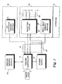
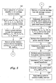
- Fig. 1 shows a functional block diagram of a preferred embodiment of an ink jet printer according to the present invention.
- the printer includes a replaceable print head 10 attached to a carriage 12 that provides for translation of the print head 10 across a print medium.
- the print head 10 is electrically connected to a printer controller 14 and a power supply 16. Since the controller 14 and the power supply 16 are preferably in a fixed location in the printer, and are not mounted on the carriage 12, electrical connections between the print head 10 and the controller 14 and power supply 16 are by way of a flexible TAB circuit 18.
- the controller 14 receives image data from a host computer, and generates control signals based on the image data to control the operation of the print head 10.
- the controller 14 also controls the power supply 16 to generate a source voltage, V s on the line 20.
- the printer includes a memory module 24 for storing operational parameters and mathematical expressions that are specific to the operation of the printer and/or the print head 10.
- the print head 10 also preferably includes a memory module 26 for storing parameters that are specific to the print head 10.
- the ink is stored in a replaceable ink reservoir, such as an ink cartridge 28, that attaches to the print head 10 and rides on the carriage 12.
- an ink cartridge memory module 30 such as a nonvolatile random-access memory (NVRAM) device, is attached to the ink cartridge 28.
- the memory module 30 stores parameters related to characteristics of the ink.
- the printer controller 14 is electrically connected to the ink cartridge memory module 30 so that the controller 14 may access memory locations within the module 30.
- the print head 10 incorporates a driver circuit 32 that receives the source voltage V s from the power supply 16 and the control signals from the controller 14.
- the driver circuit 32 decodes the control signals, and selectively generates voltage pulses across one or more resistive heating elements 34 based on the control signals and V s .
- a voltage pulse across a heating element 34 causes flow of an electrical current through the resistive material of the heating element 34.
- the flow of electrical current causes the heating element 34 to dissipate power in the form of heat.
- the heat dissipated by the heating element 34 causes nucleation of the ink that contacts the surface of the heating element 34.
- the nucleation of the ink forms a bubble which causes a droplet of ink to be expelled from an adjacent nozzle.
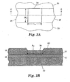
- each heating element 34 is generally rectangular in shape, as shown in Fig. 2A .
- each element 34 has a width and a length, also referred to herein as W htr and L htr , respectively.
- Fig. 2B which is a cross-sectional view taken at the section line I-I in Fig. 2A
- each heating element 34 consists of a resistive layer 38 covered by a protective overcoat 40.
- the resistive layer 38 is generally Tantalum Aluminum (TaAI), or Tantalum Nitride (TaN), or Hafnium Diboride (HfB 2 ), or some other suitable material with high resistivity and a tolerance for high temperatures.
- the resistive layer 38 To protect the resistive layer 38 from the corrosive effects of the ink and the cavitation effects of the collapsing vapor bubble, it is generally required to cover the resistive layer 38 with a composite stack of thin films, including Silicon Nitride (SiN), Silicon Carbide (SiC), and Tantalum (Ta) films.
- the SiN+SiC+Ta composite layer forms the protective overcoat 40.
- the total thickness, or height, of the SiN+SiC+Ta composite layer which forms the protective overcoat 40 is referred to herein as h po .
- the resistive layer 38 and the protective overcoat 40 are deposited onto a heater chip substrate 33.
- the substrate 33 is generally a silicon chip which is 400-800 microns thick with a 1.0-3.0 micron thick top layer 42 of thermally insulating material, such as Silicon Dioxide (SiO 2 ), Boron Phosphorus Doped Glass (BPSG), Phosphorus Doped Glass (PSG), or Spun-on Glass (SOG). Because the thermal diffusivity of silicon is approximately 600 times greater than that of ink, the purpose of the thermal insulating layer 42 is to prevent thermal energy from diffusing into the silicon substrate 33 during the time when current is flowing through the resistive layer 38.
- thermally insulating material such as Silicon Dioxide (SiO 2 ), Boron Phosphorus Doped Glass (BPSG), Phosphorus Doped Glass (PSG), or Spun-on Glass (SOG).
- one edge of the element 34 is preferably electrically connected to a conductive trace 35.
- the other end of the conductive trace 35 is connected to a switching device, such as a power FET.
- the switching device is preferably also disposed on the substrate 33.
- the other end of the switching device is preferably connected to ground.
- the other edge of the heating element 34 is electrically connected to a conductive trace 37, which connects the heating element 34 to a voltage source.
- the switching device and conductive trace 35 are connected to the voltage source, and conductive trace 37 is connected to ground.
- the conductive traces 35 and 37 are generally made from Aluminum (Al), Aluminum Copper (AlCu), Aluminum Silicon (AISi), or some other low resistivity aluminum alloy. Since ink is corrosive to aluminum, the conductive traces 35 and 37 are typically covered with the same SiN+SiC+Ta protective layer as that covering the heater 34.
- ED htr V hir 2 A hir ⁇ R hir ⁇ t pw .
- the energy density at the surface of the heating element 34, ED htr may be adjusted by adjusting the amplitude and/or the pulse width of the voltage pulse provided by the driver circuit 32 to the heating element 34.
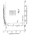
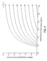
- FIG. 3 shows a typical response curve indicating normalized mass of the ink droplet as a function of the energy density, ED htr , provided to the surface of the heating element 34.
- the data points plotted in Fig. 3 were measured using five different print heads (a-e), all having heating elements 34 with individual areas of 1056 ⁇ m 2 . It has been determined that this type of response also applies to heating elements 34 having areas ranging from 300 ⁇ m 2 to 2300 ⁇ m 2 . The binary nature of this response is due to the heat transfer and ink bubble nucleation process.
- the minimum energy density as indicated in Fig. 1 is also referred to herein as the optimum energy density, ED opt .
- ED opt the optimum energy density
- ED opt the optimum energy density
- the adjustment of the amplitude and duration of the energy pulse to provide the optimum energy density, ED opt requires taking into account several factors related to characteristics of the print head 10, characteristics of the heating element 34, and characteristics of the ink. If these factors are known, and their interrelationships are understood, then ED opt may be determined and controlled for practically any combination of ink type and print head heater chip design.
- ED opt b 2 + b 3 ⁇ h po + b 4 ⁇ 22 + ⁇ ⁇ T + b 5 PD ⁇ 10 - 9
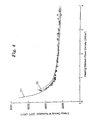
- the optimal energy density operating point ED opt is identified at the knee of the curve.
- the curved region identifies the time during which the thermal wave begins to propagate through the thermal insulation layer 42.
- the heating rates are exceedingly high. These high heating rates cause the superheat limit to be reached before the thermal wave has had time to propagate through the insulation layer 42 which separates the resistive layer 38 from the substrate 33.
- the ED * versus PD response is nearly flat, thereby indicating that little to no thermal energy is escaping into the silicon 33 through the insulation layer 42.
- Fig. 4 Also shown in Fig. 4 is the response in the low power density regime.
- the energy density at nucleation begins to grow exponentially because the long pulse times associated with low power density permit the thermal wave to penetrate the insulation layer 42 and diffuse into the silicon substrate 33.
- ED * a 1 + a 2 ⁇ h po + a 3 ⁇ 22 + ⁇ ⁇ T + a 4 PD ⁇ 10 - 9 , where a 1 , a 2 , a 3 , and a 4 are ink-specific coefficients; ⁇ T, PD, and h po are as identified previously; and ED * is the heater energy density at the film boiling onset (J/m 2 ).
- Typical values for a 1 , a 2 , a 3 , and a 4 are listed in Table I below. Table I.
- Table I Coefficient Pigment-based Ink Dye-based Ink a 1 729 233 a 2 1212 1034 a 3 -8.54 -6.74 a 4 1020 924
- FIG. 4 A typical correlation between the experimental results, the two dimensional finite element heat transfer modeling, and equation (4a) is shown in Fig. 4 .
- This particular set of experimental results was obtained using a heating element 34 having a length and width of 29.5 microns, and pigment-based ink.
- Curve C1 of Fig. 4 corresponds to equation (4a), curve C2 to the heat transfer model, and the triangle symbols ( ⁇ ) correspond to the measured experimental data points.
- the invention determines ED opt because that identifies how the heater is pulsed in operation.
- the ED * point is more esoteric in nature, since the print head will not be operated at this point in the product.
- the coefficients a 1 , a 2 , a 3 , and a 4 are not stored in the memory modules of the preferred embodiment.
- ink-specific coefficients ( a n , b n ) differ for pigment-based ink and dye-based ink is that during the high pressure phase of the bubble growth process, the bubble wall experiences an acceleration on the order of one million times the gravitational pull of the earth. This is not a problem for dye-based inks, but pigment-based inks have colorant particles of a finite size. Pigment particles are held in solution with a delicate balance of the electromechanical forces between water, dispersant, pigment, and humectant. These weak forces are not sufficient to hold the pigment particles in solution under high accelerations.
- t opt b 2 + b 3 ⁇ h po + b 4 ⁇ 22 + ⁇ ⁇ T + b 5 PD ⁇ 10 - 9 PD
- V opt i opt ⁇ R hir
- V opt L hir ⁇ PD ⁇ R s .
- V s V opt ⁇ R hir + R d
- V hir V opt ⁇ R d
- W hir W hir R s ⁇ L hir + 1 .
- V s L hir ⁇ PD ⁇ R s ⁇ R d ⁇ W hir R s ⁇ L hir + 1 .
- the printer controller 14 Based on equations (8) and (13), the printer controller 14 adjusts the pulse width, t opt , and/or the supply voltage, V s , to obtain the optimum energy density, ED opt , for any combination of ink and heater chip, based on values for the variables listed above. According to the invention, these values are stored in either the print head memory module 26 or in the ink cartridge memory module 30.
- the coefficients b 1 , b 2 , b 3 , b 4 , and b 5 , heating element dimensional values h po , W htr , and L htr , the heating element power density PD, the logic switching device resistance R x , and the resistivity of the heating element 34 R s are stored in the print head memory module 26.
- the print head operating point offset temperature ⁇ T is preferably stored in the ink cartridge memory module 30.
- An ink identifier, which identifies the type of ink in the ink cartridge 28, is also preferably stored in the ink cartridge memory module 30.
- the regression equations listed above are stored in the printer memory module 24.
- the printer controller 14 retrieves the equations from the memory module 24, retrieves the variable values from the ink cartridge memory module 30 and the print head memory module 26, and determines optimum values for the pulse width, t opt , and the current, i, based thereon.
- values for the ink identifier and the print head operating point offset temperature, ⁇ T are stored in the ink cartridge memory module 30 (step 100).
- the ink identifier may have a value of 0 to indicate that pigment-based ink is loaded in the cartridge, or a value of 1 to indicate dye-based ink.
- a typical range for ⁇ T is between 10 °C and 40 °C.
- values for W htr , L htr , h po , PD, R s , b 2 , b 3 , b 4 , and b 5 are stored in the print head memory module 26 (step 102).
- Typical values for the heating element length, width, and thickness dimensions, W htr , L htr , and h po are 29.5 ⁇ m, 29.5 ⁇ m, and 1.21 ⁇ m, respectively.
- a typical value for the resistivity of a heating element 34 having a TaAl resistive layer 38 is 28.2 ⁇ /square.
- a typical value for the power density, PD is 2.5 GW/m 2 .
- two sets of values for the ink-related coefficients are stored: one set for dye-based ink and another set for pigment-based ink. Typical values of these coefficients are listed in Table II. Table II. Coefficient Pigment-based Ink Dye-based Ink b 2 502.6 -13.97 b 3 2050.2 1997.2 b 4 -16.337 -17.93 b 5 2905.8 3663.1
- a firmware module for calculating t opt according to equation (8) is stored in the printer memory module 24 (step 104).
- a firmware module for calculating i opt or V opt according to equation (6) or (11) is also stored in the printer memory module 24 (step 106).
- the printer controller 14 accesses the ink cartridge memory module 30 and retrieves the values for the ink identifier and ⁇ T (step 108). Based on the value of the ink identifier, i.e. 1 or 0, the controller 14 determines which values of b 2 , b 3 , b 4 , and b 5 (Table I) to retrieve from the print head memory module 26 (step 110). The controller 14 then accesses the print head memory module 26 and retrieves the values for b 2 , b 3 , b 4 , b 5 , W htr , L htr , h po , PD, and R s (step 112).
- the controller 14 controls the power supply 16 to set the supply voltage, V s , accordingly.
- the only value that is actually stored in the memory module 26 of the preferred embodiment is the on-resistance of the power FET and the resistance of the power and ground traces 35 and 37 on the substrate 33.
- Other resistance values such as cables and interconnects, are external to the print head 10 and are generally very small compared to the components located on the substrate 33.
- a viable option is to not store the off-chip component values going into the R d term.
- nominal resistance values for the cables and interconnects and other components external to the print head 10 may be stored in the printer memory module 24. These external resistance values may be extracted from the printer memory module 24 and added to the print head resistance values making up the R d term.
- the printer controller 14 controls the driver circuit 32 to selectively provide energy pulses to the heating elements 34, where the energy pulses have a voltage amplitude of V opt (7.83 volts) and a pulse width of t opt (1.253 ⁇ sec) ( steps 122 and 124).
- one of the goals in designing an ink jet print head is to reduce the amount of power dissipated in the print head, and thereby reduce the amount of heat generated by the print head.
- One of the most practical means of reducing power dissipation is to reduce the amount of energy per pulse required to properly eject a droplet of ink.
- one design goal is to push the knee of the response curve of Fig. 3 to the left. This is accomplished by using thinner films in the formation of the heating elements 34.
- the ink coefficient b 1 is dependent on the heat dissipation mechanism of the print head 10. Most of the heat is carried away by convection (i.e. by the mass flow of ink through the device). In other words, as print density increases, so does input power, but so does the mass flow rate of ink. As the liquid ink passes the silicon chip on its way to the paper, it picks up thermal energy by convection. When the ink is jetted onto the paper, it leaves the control volume of the chip, taking with it a finite quantity of thermal energy.
- the mass of the droplets produced by a multi-color print head is generally much less than the mass of the droplets produced by a monochromatic print head, the b 1 coefficients for a multi-color head are different than for a monochromatic head because the mass flow rates per Watt are different.
- R x in equation (7) is a resistance value that accounts for circuit resistances within the driver circuit 32.
- R x includes the source-to-drain resistance of the power FET switching device 35 and the resistance of the associated metal traces within the driver circuit 32 and the ground trace 37.
- a typical value of R x is 7.2 ⁇ .
- Shown in Fig. 6 is a plot, based on the relationship of equation (7), showing maximum protective overcoat thickness, h max , as a function of heating element power density, PD , for a mono-color print head producing 28 ng pigment-based ink droplets and providing 20% coverage at 6.8 PPM.
- the various curves plotted in Fig. 6 are for various values of print head offset temperature, ⁇ T , ranging from 10 to 50°C.
- the curves of Fig. 6 apply to a print head in which R s is 28.2 ⁇ /square, L htr and W htr are 29.5 ⁇ m, and R x is 7.2 ⁇ .
- Fig. 7 depicts a plot of h max as a function of PD for a three-color print head producing 7 ng dye-based ink droplets and providing 10% coverage at 2.6 PPM.
- the curves of Fig. 7 apply to a print head in which R, is 28.2 ⁇ /square, L htr is 37.5 ⁇ m, W htr is 14.0 ⁇ m, and R x is 4.3 ⁇ .
- another embodiment of the invention provides a system for determining the maximum overcoat thickness, h max , for a particular ink jet print head.
- the system is implemented as a computer algorithm running on a computer processor, such as in a laptop computer, personal computer, or workstation computer.
- the algorithm representing the relationship of equation (7) is retrieved from computer memory (step 200).
- Known values for W htr and L htr are input into the algorithm from an input device, such as a keyboard, or from a memory location (step 202).
- Known values for PD, R s , b 1 , b 2 , b 3 , b 4 , b 5 , and ⁇ T are also input into the algorithm (steps 204, 206, and 208).
- the system determines h max based on the relationship of equation (7) and the known values of W htr , L htr , PD, R s , b 1 , b 2 , b 3 , b 4 , b 5 , and ⁇ T .
- the computed value of h max is then provided to a user by way of an output device, such as a computer monitor or printer.
Landscapes
- Particle Formation And Scattering Control In Inkjet Printers (AREA)
- Ink Jet (AREA)
Applications Claiming Priority (2)
| Application Number | Priority Date | Filing Date | Title |
|---|---|---|---|
| US09/634,143 US6467864B1 (en) | 2000-08-08 | 2000-08-08 | Determining minimum energy pulse characteristics in an ink jet print head |
| EP01957430A EP1309450A4 (en) | 2000-08-08 | 2001-08-03 | DETERMINING THE MINIMUM CHARACTERISTICS OF ENERGY PULSES IN AN INK JET PRESSURE HEAD |
Related Parent Applications (1)
| Application Number | Title | Priority Date | Filing Date |
|---|---|---|---|
| EP01957430A Division EP1309450A4 (en) | 2000-08-08 | 2001-08-03 | DETERMINING THE MINIMUM CHARACTERISTICS OF ENERGY PULSES IN AN INK JET PRESSURE HEAD |
Publications (1)
| Publication Number | Publication Date |
|---|---|
| EP1958776A1 true EP1958776A1 (en) | 2008-08-20 |
Family
ID=24542591
Family Applications (3)
| Application Number | Title | Priority Date | Filing Date |
|---|---|---|---|
| EP08003942A Withdrawn EP1958776A1 (en) | 2000-08-08 | 2001-08-03 | Determining minimum energy pulse characteristics in an ink jet print head |
| EP01957430A Withdrawn EP1309450A4 (en) | 2000-08-08 | 2001-08-03 | DETERMINING THE MINIMUM CHARACTERISTICS OF ENERGY PULSES IN AN INK JET PRESSURE HEAD |
| EP08003941A Withdrawn EP1952989A3 (en) | 2000-08-08 | 2001-08-03 | Determining minimum energy pulse characteristics in an ink jet print head |
Family Applications After (2)
| Application Number | Title | Priority Date | Filing Date |
|---|---|---|---|
| EP01957430A Withdrawn EP1309450A4 (en) | 2000-08-08 | 2001-08-03 | DETERMINING THE MINIMUM CHARACTERISTICS OF ENERGY PULSES IN AN INK JET PRESSURE HEAD |
| EP08003941A Withdrawn EP1952989A3 (en) | 2000-08-08 | 2001-08-03 | Determining minimum energy pulse characteristics in an ink jet print head |
Country Status (10)
| Country | Link |
|---|---|
| US (1) | US6467864B1 (enExample) |
| EP (3) | EP1958776A1 (enExample) |
| JP (2) | JP2004517753A (enExample) |
| KR (3) | KR20070103514A (enExample) |
| CN (2) | CN1208192C (enExample) |
| AU (2) | AU7917701A (enExample) |
| BR (1) | BR0113111A (enExample) |
| CA (1) | CA2417968C (enExample) |
| MX (1) | MXPA03001075A (enExample) |
| WO (1) | WO2002011992A2 (enExample) |
Families Citing this family (12)
| Publication number | Priority date | Publication date | Assignee | Title |
|---|---|---|---|---|
| WO2002055310A1 (en) * | 2001-01-09 | 2002-07-18 | Encad, Inc. | Ink jet printhead quality management system and method |
| US7059699B2 (en) * | 2001-07-20 | 2006-06-13 | Seiko Epson Corporation | Ink tank with data storage for drive signal data and printing apparatus with the same |
| KR100470579B1 (ko) * | 2002-11-02 | 2005-03-08 | 삼성전자주식회사 | 잉크젯 기록 장치의 제어장치 및 제어방법 |
| US7080896B2 (en) * | 2004-01-20 | 2006-07-25 | Lexmark International, Inc. | Micro-fluid ejection device having high resistance heater film |
| US9296214B2 (en) | 2004-07-02 | 2016-03-29 | Zih Corp. | Thermal print head usage monitor and method for using the monitor |
| US7178904B2 (en) * | 2004-11-11 | 2007-02-20 | Lexmark International, Inc. | Ultra-low energy micro-fluid ejection device |
| JP2006216822A (ja) * | 2005-02-04 | 2006-08-17 | Hitachi High-Technologies Corp | ウェハ処理装置およびウェハ処理方法 |
| US7673957B2 (en) * | 2005-05-04 | 2010-03-09 | Lexmark International, Inc. | Method for determining an optimal non-nucleating heater pulse for use with an ink jet printhead |
| US8721203B2 (en) | 2005-10-06 | 2014-05-13 | Zih Corp. | Memory system and method for consumables of a printer |
| US8684501B2 (en) | 2010-04-29 | 2014-04-01 | Hewlett-Packard Development Company, L.P. | Fluid ejection device |
| JP6335436B2 (ja) * | 2013-04-26 | 2018-05-30 | キヤノン株式会社 | 液体吐出ヘッドの製造方法 |
| CN107073955B (zh) | 2014-10-30 | 2018-10-12 | 惠普发展公司,有限责任合伙企业 | 喷墨打印头 |
Citations (8)
| Publication number | Priority date | Publication date | Assignee | Title |
|---|---|---|---|---|
| US4590487A (en) * | 1983-09-29 | 1986-05-20 | Fuji Xerox Co., Ltd. | Thermal recording apparatus |
| US5006866A (en) * | 1988-10-31 | 1991-04-09 | Kabushiki Kaisha Toshiba | Thermal printing apparatus responsive to estimated stored heat of the heating element |
| EP0458507A2 (en) * | 1990-05-25 | 1991-11-27 | Hewlett-Packard Company | Method for adjusting a strobe pulse for a thermal line array printer |
| US5208607A (en) * | 1990-09-03 | 1993-05-04 | Ricoh Company, Ltd. | Thermal recording method using drive signal pulse widths changed at time intervals within thermal head temperature measuring time intervals |
| US5608442A (en) * | 1994-08-31 | 1997-03-04 | Lasermaster Corporation | Heating control for thermal printers |
| JPH09150516A (ja) * | 1995-11-28 | 1997-06-10 | Kyocera Corp | インクジェットヘッド |
| JPH11994A (ja) * | 1997-06-11 | 1999-01-06 | Fuji Xerox Co Ltd | 液体噴射記録装置およびその駆動方法 |
| JP2000185426A (ja) * | 1998-12-21 | 2000-07-04 | Seiko Instruments Inc | サーマルプリンタ装置 |
Family Cites Families (17)
| Publication number | Priority date | Publication date | Assignee | Title |
|---|---|---|---|---|
| US4872028A (en) | 1988-03-21 | 1989-10-03 | Hewlett-Packard Company | Thermal-ink-jet print system with drop detector for drive pulse optimization |
| US5177481A (en) | 1990-08-01 | 1993-01-05 | Mita Industrial Co., Ltd. | Data generator for controlling pulse width |
| US5726690A (en) | 1991-05-01 | 1998-03-10 | Hewlett-Packard Company | Control of ink drop volume in thermal inkjet printheads by varying the pulse width of the firing pulses |
| US5223853A (en) | 1992-02-24 | 1993-06-29 | Xerox Corporation | Electronic spot size control in a thermal ink jet printer |
| JPH0631932A (ja) | 1992-07-14 | 1994-02-08 | Fuji Xerox Co Ltd | インクジェット記録装置 |
| DE69409020T2 (de) | 1993-02-05 | 1998-07-02 | Hewlett Packard Co | System zur Reduzierung der Antriebsenergie in einem thermischen Tintenstrahlschnelldrucker |
| US5418558A (en) | 1993-05-03 | 1995-05-23 | Hewlett-Packard Company | Determining the operating energy of a thermal ink jet printhead using an onboard thermal sense resistor |
| EP0649746A1 (en) | 1993-10-26 | 1995-04-26 | Hewlett-Packard Company | Variable halftone operation inkjet printheads |
| US5428376A (en) | 1993-10-29 | 1995-06-27 | Hewlett-Packard Company | Thermal turn on energy test for an inkjet printer |
| US5682185A (en) | 1993-10-29 | 1997-10-28 | Hewlett-Packard Company | Energy measurement scheme for an ink jet printer |
| US5519417A (en) | 1994-03-31 | 1996-05-21 | Xerox Corporation | Power control system for a printer |
| US5751302A (en) | 1996-03-29 | 1998-05-12 | Xerox Corporation | Transducer power dissipation control in a thermal ink jet printhead |
| US6315381B1 (en) * | 1997-10-28 | 2001-11-13 | Hewlett-Packard Company | Energy control method for an inkjet print cartridge |
| US5980025A (en) * | 1997-11-21 | 1999-11-09 | Xerox Corporation | Thermal inkjet printhead with increased resistance control and method for making the printhead |
| US6039436A (en) * | 1998-03-12 | 2000-03-21 | Xerox Corporation | Thermal ink-jet printhead with lateral thermal insulation for the heating elements |
| US6039736A (en) * | 1998-09-29 | 2000-03-21 | Sherwood Services Ag | Side-Fire coagulator |
| US6139131A (en) | 1999-08-30 | 2000-10-31 | Hewlett-Packard Company | High drop generator density printhead |
-
2000
- 2000-08-08 US US09/634,143 patent/US6467864B1/en not_active Expired - Lifetime
-
2001
- 2001-08-03 KR KR1020077021980A patent/KR20070103514A/ko not_active Ceased
- 2001-08-03 AU AU7917701A patent/AU7917701A/xx active Pending
- 2001-08-03 KR KR1020077021977A patent/KR20070103513A/ko not_active Ceased
- 2001-08-03 AU AU2001279177A patent/AU2001279177B2/en not_active Ceased
- 2001-08-03 WO PCT/US2001/024437 patent/WO2002011992A2/en not_active Ceased
- 2001-08-03 CN CNB018154298A patent/CN1208192C/zh not_active Expired - Fee Related
- 2001-08-03 MX MXPA03001075A patent/MXPA03001075A/es active IP Right Grant
- 2001-08-03 CA CA002417968A patent/CA2417968C/en not_active Expired - Fee Related
- 2001-08-03 EP EP08003942A patent/EP1958776A1/en not_active Withdrawn
- 2001-08-03 KR KR1020037001734A patent/KR100840202B1/ko not_active Expired - Fee Related
- 2001-08-03 BR BR0113111-7A patent/BR0113111A/pt not_active IP Right Cessation
- 2001-08-03 EP EP01957430A patent/EP1309450A4/en not_active Withdrawn
- 2001-08-03 JP JP2002517310A patent/JP2004517753A/ja active Pending
- 2001-08-03 EP EP08003941A patent/EP1952989A3/en not_active Withdrawn
- 2001-08-03 CN CNA200410100393XA patent/CN1623780A/zh active Pending
-
2007
- 2007-06-06 JP JP2007149876A patent/JP2007261280A/ja active Pending
Patent Citations (9)
| Publication number | Priority date | Publication date | Assignee | Title |
|---|---|---|---|---|
| US4590487A (en) * | 1983-09-29 | 1986-05-20 | Fuji Xerox Co., Ltd. | Thermal recording apparatus |
| US5006866A (en) * | 1988-10-31 | 1991-04-09 | Kabushiki Kaisha Toshiba | Thermal printing apparatus responsive to estimated stored heat of the heating element |
| EP0458507A2 (en) * | 1990-05-25 | 1991-11-27 | Hewlett-Packard Company | Method for adjusting a strobe pulse for a thermal line array printer |
| US5208607A (en) * | 1990-09-03 | 1993-05-04 | Ricoh Company, Ltd. | Thermal recording method using drive signal pulse widths changed at time intervals within thermal head temperature measuring time intervals |
| US5608442A (en) * | 1994-08-31 | 1997-03-04 | Lasermaster Corporation | Heating control for thermal printers |
| JPH09150516A (ja) * | 1995-11-28 | 1997-06-10 | Kyocera Corp | インクジェットヘッド |
| JPH11994A (ja) * | 1997-06-11 | 1999-01-06 | Fuji Xerox Co Ltd | 液体噴射記録装置およびその駆動方法 |
| JP2000185426A (ja) * | 1998-12-21 | 2000-07-04 | Seiko Instruments Inc | サーマルプリンタ装置 |
| US6382774B1 (en) * | 1998-12-21 | 2002-05-07 | Seiko Instruments Inc. | Printer having energizing pulse width calculating means |
Non-Patent Citations (3)
| Title |
|---|
| PATENT ABSTRACTS OF JAPAN vol. 1997, no. 10 31 October 1997 (1997-10-31) * |
| PATENT ABSTRACTS OF JAPAN vol. 1999, no. 04 30 April 1999 (1999-04-30) * |
| PATENT ABSTRACTS OF JAPAN vol. 2000, no. 10 17 November 2000 (2000-11-17) * |
Also Published As
| Publication number | Publication date |
|---|---|
| JP2007261280A (ja) | 2007-10-11 |
| EP1952989A3 (en) | 2008-08-20 |
| CN1454147A (zh) | 2003-11-05 |
| AU7917701A (en) | 2002-02-18 |
| KR20030027006A (ko) | 2003-04-03 |
| CA2417968A1 (en) | 2002-02-14 |
| KR100840202B1 (ko) | 2008-06-23 |
| EP1952989A2 (en) | 2008-08-06 |
| WO2002011992A2 (en) | 2002-02-14 |
| JP2004517753A (ja) | 2004-06-17 |
| AU2001279177B2 (en) | 2004-05-20 |
| CA2417968C (en) | 2006-05-23 |
| EP1309450A4 (en) | 2005-04-06 |
| WO2002011992A3 (en) | 2002-06-13 |
| US6467864B1 (en) | 2002-10-22 |
| EP1309450A2 (en) | 2003-05-14 |
| BR0113111A (pt) | 2003-06-10 |
| MXPA03001075A (es) | 2004-03-10 |
| KR20070103513A (ko) | 2007-10-23 |
| KR20070103514A (ko) | 2007-10-23 |
| CN1208192C (zh) | 2005-06-29 |
| CN1623780A (zh) | 2005-06-08 |
Similar Documents
| Publication | Publication Date | Title |
|---|---|---|
| US5036337A (en) | Thermal ink jet printhead with droplet volume control | |
| JP2007261280A (ja) | インクジェット・プリントヘッドにおける最小エネルギーパルス特性の決定 | |
| US4935752A (en) | Thermal ink jet device with improved heating elements | |
| JP3526822B2 (ja) | 高密度の液滴発生器を有するプリントヘッド | |
| CA2048277C (en) | Control of energy to thermal inkjet heating elements | |
| US6422677B1 (en) | Thermal ink jet printhead extended droplet volume control | |
| EP1651442A2 (en) | Improved ink jet printheads | |
| AU2001279177A1 (en) | Determining minimum energy pulse characteristics in an ink jet print head | |
| TW419423B (en) | Ink jet printer having driver circuit for generating warming and firing pulses for heating elements | |
| JP2001080074A (ja) | インクジェットプリンタ用プリントヘッド | |
| KR100440109B1 (ko) | 잉크젯 프린트 헤드 장치 | |
| US6318847B1 (en) | Segmented heater resistor for producing a variable ink drop volume in an inkjet drop generator | |
| EP1778497B1 (en) | Ground structure for temperature-sensing resistor noise reduction | |
| US20040179070A1 (en) | Ink-jet recording head and ink-jet recording apparatus | |
| JP4311026B2 (ja) | インク吐出ヘッド制御装置、及びインク吐出装置 | |
| US5980024A (en) | Ink jet print head and a method of driving ink therefrom | |
| JPH0820110A (ja) | サーマルインクジェットプリンタ | |
| JPH0441242A (ja) | インクジェット記録装置 | |
| JP3436623B2 (ja) | インク噴射記録装置およびインク噴射記録方法 | |
| JPH0976498A (ja) | インク噴射記録ヘッド | |
| JP2828525B2 (ja) | 液体噴射記録ヘッドの製造方法、該方法により製造された液体噴射記録ヘッドおよび該液体噴射記録ヘッドを装着した液体噴射記録装置 | |
| JP2003246068A (ja) | インクジェットヘッド | |
| JPH06238900A (ja) | インクジェット記録ヘッドおよび該ヘッドを用いたインクジェット記録装置 | |
| JPH06191027A (ja) | インクジェット記録ヘッドおよびインクジェット記録装置 | |
| JP2003246067A (ja) | インクジェットプリンタ |
Legal Events
| Date | Code | Title | Description |
|---|---|---|---|
| PUAI | Public reference made under article 153(3) epc to a published international application that has entered the european phase |
Free format text: ORIGINAL CODE: 0009012 |
|
| AC | Divisional application: reference to earlier application |
Ref document number: 1309450 Country of ref document: EP Kind code of ref document: P |
|
| AK | Designated contracting states |
Kind code of ref document: A1 Designated state(s): DE FR GB |
|
| STAA | Information on the status of an ep patent application or granted ep patent |
Free format text: STATUS: THE APPLICATION HAS BEEN WITHDRAWN |
|
| 18W | Application withdrawn |
Effective date: 20090202 |