EP0458507A2 - Method for adjusting a strobe pulse for a thermal line array printer - Google Patents
Method for adjusting a strobe pulse for a thermal line array printer Download PDFInfo
- Publication number
- EP0458507A2 EP0458507A2 EP91304320A EP91304320A EP0458507A2 EP 0458507 A2 EP0458507 A2 EP 0458507A2 EP 91304320 A EP91304320 A EP 91304320A EP 91304320 A EP91304320 A EP 91304320A EP 0458507 A2 EP0458507 A2 EP 0458507A2
- Authority
- EP
- European Patent Office
- Prior art keywords
- strobe pulse
- print head
- pulse width
- strobe
- look
- Prior art date
- Legal status (The legal status is an assumption and is not a legal conclusion. Google has not performed a legal analysis and makes no representation as to the accuracy of the status listed.)
- Granted
Links
Images

Classifications
-
- B—PERFORMING OPERATIONS; TRANSPORTING
- B41—PRINTING; LINING MACHINES; TYPEWRITERS; STAMPS
- B41J—TYPEWRITERS; SELECTIVE PRINTING MECHANISMS, i.e. MECHANISMS PRINTING OTHERWISE THAN FROM A FORME; CORRECTION OF TYPOGRAPHICAL ERRORS
- B41J2/00—Typewriters or selective printing mechanisms characterised by the printing or marking process for which they are designed
- B41J2/315—Typewriters or selective printing mechanisms characterised by the printing or marking process for which they are designed characterised by selective application of heat to a heat sensitive printing or impression-transfer material
- B41J2/32—Typewriters or selective printing mechanisms characterised by the printing or marking process for which they are designed characterised by selective application of heat to a heat sensitive printing or impression-transfer material using thermal heads
- B41J2/35—Typewriters or selective printing mechanisms characterised by the printing or marking process for which they are designed characterised by selective application of heat to a heat sensitive printing or impression-transfer material using thermal heads providing current or voltage to the thermal head
- B41J2/355—Control circuits for heating-element selection
- B41J2/36—Print density control
Definitions
- the invention relates to thermal printers having printing elements driven by strobe pulses whose power may be adjusted.
- the invention relates to a method of adjusting power to such a printing element.
- M. Minowa discloses a method for controlling the pulse width of strobe pulses applied to printing elements of a thermal printer.
- the system of Minowa is of the feedback type where a decrease in the print head element output voltage is measured and the width of a strobe pulse is correspondingly increased. Conversely, the pulse width is decreased in response to increases in the output voltage.
- Y. Ito discloses a similar system using different circuit elements.
- An object of the invention was to more accurately control the power delivered to a printing element by taking into account nonlinear quantities such as printing speed and history level, in establishing strobe pulse duration.
- a printing method wherein print head pulse width is varied in accord with data derived from a look-up table.
- a predictive model of print element behavior is employed where the model relates speed, history level as well as voltage, temperature and resistance to strobe pulse duration.
- a semiconductor memory forms a look-up table for storing desired or target strobe pulse durations computed from various power supply voltage levels, taking into account parameters mentioned above.
- a strobe pulse may be initiated at a print head element. Once the pulse is initiated, periodic real time measurements are made of power supply voltage levels. Reference is made to the look-up table to obtain the target pulse width value using the real time measurement. The actual strobe pulse is continued so long as the target pulse width has not been exceeded. Continued measurements of the power supply level are made and further look-up values are found. Each time a new pulse width is obtained from the table, a comparison must be made to see whether the actual elapsed time exceeds the target value. Once the target value is equaled or exceeded, the strobe pulse is terminated.
- the thermal line array may be turned on multiple times per scan line in order to adjust the energy applied to individual dot elements based on the amount of preheating they have experienced in previous scan lines.
- Each of these multiple strobes is assigned a history level which points to a section of the strobe width look-up table.
- Fig. 1 is a flow diagram showing steps for establishing strobe pulse width in accord with the invention.
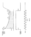
- Fig. 2 is a timing diagram showing strobe width in comparison to print head power supply levels for different elapsed times.
- a look-up table is created giving values for a target strobe width which depends upon power supply voltage, average resistance and print head element temperature.
- the voltage function v is described by the following equation: where K0 and K1 are empirical constants which are dependent on print speed and history level. The constants are assigned to each speed and to each history level, the history level relating to previously observed print characteristics whereby a desired level of contrast can be obtained.
- the voltage, V is the measured power supply voltage and is the only quantity measured in real time. All other quantities are previously measured so that different strobe pulse widths are available for different previously measured functions.
- R A is the average element resistance
- R D is the resistance of the element driver so that R A plus R D are equal to the total resistance in the print head element circuit.
- T 1.0 + ((25.0 - T P ) x 0.007) where T P is equal to print head temperature in degrees Celsius.
- the temperature function is supplied by the print element manufacturer.
- a print head strobe pulse is initiated at block 11. Shortly thereafter, power supply voltage is measured, as indicated by block 13. The supply measurement is converted to digital form and then the target strobe width is obtained from the look-up table, indicated by block 15. The target pulse width obtained from the table is compared to the actual elapsed time since the initiation of the strobe pulse. When the actual elapsed time is equal to or exceeds the target strobe the print head element is turned off, indicated by block 17 with the comparison indicated by block 19. If the measured strobe pulse width does not exceed the target width, as indicated by block 21, the strobe width is extended and new comparisons are made after obtaining further power supply voltage level measurements, indicated by line 23. The entire process is repeated until the pulse width of the strobe exceeds the target width from the table. As previously mentioned, the print head is then turned off, indicated by block 17.
- elapsed time of a strobe pulse width is shown on the lower plot in milliseconds.
- the strobe pulse is initiated, indicated by the vertical line 31.
- periodic measurements of the print head power supply level are made, indicated by the vertical lines 33 in the upper plot.
- the actual print head power supply level is indicated by the curve 35.
- a voltage measurement is made. The value found is below the upper level 39, existing at the initiation of the strobe pulse.
- the look-up table is consulted for the voltage level found within the circle 37 and a number is obtained from the table, corresponding to a target pulse width for this particular voltage. Assume that the target value is 190 microseconds. Since at the measurement time, only about 20 microseconds have elapsed, the strobe pulse is continued.
- the power supply voltage level is read, indicated by circle 51 and a target strobe pulse length of 310 microseconds is found which has now been exceeded by the actual elapsed time. Accordingly, the strobe pulse is terminated, indicated by vertical line 53.
- history level was used to adjust the energy applied to individual dot elements based on their recent history in order to obtain consistent contrast and eliminate tailing. History level could also be used to vary the contrast of individual dots in order to create gray-scale images.
Abstract
Description
- The invention relates to thermal printers having printing elements driven by strobe pulses whose power may be adjusted. In particular, the invention relates to a method of adjusting power to such a printing element.
- In U.S. Pat. No. 4,113,391, M. Minowa discloses a method for controlling the pulse width of strobe pulses applied to printing elements of a thermal printer. The system of Minowa is of the feedback type where a decrease in the print head element output voltage is measured and the width of a strobe pulse is correspondingly increased. Conversely, the pulse width is decreased in response to increases in the output voltage. In U.S. Pat. No. 4,168,421, Y. Ito discloses a similar system using different circuit elements.
- The prior art recognized that factors such as print element resistance, temperature and current level can affect print quality. Generally, the control mechanisms adapted to achieve a desired print quality involved simple models. For example, in the aforementioned patents, when voltage of the print element power supply dropped, the pulse width was increased and vice versa. Such models were quite useful, but did not take into account other factors which might cause the model to become nonlinear. For example, printing speed and history level were not taken into account. The latter parameter is associated with applications for multiple strobes or line passes, and is used to achieve the desired dot contrast relative to a print medium.
- An object of the invention was to more accurately control the power delivered to a printing element by taking into account nonlinear quantities such as printing speed and history level, in establishing strobe pulse duration.
- The above object has been achieved in a printing method wherein print head pulse width is varied in accord with data derived from a look-up table. A predictive model of print element behavior is employed where the model relates speed, history level as well as voltage, temperature and resistance to strobe pulse duration. In accord with the present invention a semiconductor memory forms a look-up table for storing desired or target strobe pulse durations computed from various power supply voltage levels, taking into account parameters mentioned above.
- Once the relationships are stored, a strobe pulse may be initiated at a print head element. Once the pulse is initiated, periodic real time measurements are made of power supply voltage levels. Reference is made to the look-up table to obtain the target pulse width value using the real time measurement. The actual strobe pulse is continued so long as the target pulse width has not been exceeded. Continued measurements of the power supply level are made and further look-up values are found. Each time a new pulse width is obtained from the table, a comparison must be made to see whether the actual elapsed time exceeds the target value. Once the target value is equaled or exceeded, the strobe pulse is terminated.
- This procedure is repeated each time the thermal line array is turned on. The thermal line array may be turned on multiple times per scan line in order to adjust the energy applied to individual dot elements based on the amount of preheating they have experienced in previous scan lines. Each of these multiple strobes is assigned a history level which points to a section of the strobe width look-up table.
- Fig. 1 is a flow diagram showing steps for establishing strobe pulse width in accord with the invention.
- Fig. 2 is a timing diagram showing strobe width in comparison to print head power supply levels for different elapsed times.
- In thermal printing, it is desirable to obtain consistent print quality with minimal power consumption over a wide range of operating conditions. In accord with the present invention, a look-up table is created giving values for a target strobe width which depends upon power supply voltage, average resistance and print head element temperature. This equation is expressed as

where W is the strobe width, V is a voltage function, R is a resistance function and T is a temperature function. The voltage function v is described by the following equation:
where K0 and K1 are empirical constants which are dependent on print speed and history level. The constants are assigned to each speed and to each history level, the history level relating to previously observed print characteristics whereby a desired level of contrast can be obtained. The voltage, V, is the measured power supply voltage and is the only quantity measured in real time. All other quantities are previously measured so that different strobe pulse widths are available for different previously measured functions. - The resistance of function R is given by the following formula:

where RA is the average element resistance and RD is the resistance of the element driver so that RA plus RD are equal to the total resistance in the print head element circuit. - The temperature function is given by the following equation:

where TP is equal to print head temperature in degrees Celsius. The temperature function is supplied by the print element manufacturer. - With reference to Fig. 1, a print head strobe pulse is initiated at
block 11. Shortly thereafter, power supply voltage is measured, as indicated byblock 13. The supply measurement is converted to digital form and then the target strobe width is obtained from the look-up table, indicated byblock 15. The target pulse width obtained from the table is compared to the actual elapsed time since the initiation of the strobe pulse. When the actual elapsed time is equal to or exceeds the target strobe the print head element is turned off, indicated byblock 17 with the comparison indicated byblock 19. If the measured strobe pulse width does not exceed the target width, as indicated byblock 21, the strobe width is extended and new comparisons are made after obtaining further power supply voltage level measurements, indicated byline 23. The entire process is repeated until the pulse width of the strobe exceeds the target width from the table. As previously mentioned, the print head is then turned off, indicated byblock 17. - With reference to Fig. 2, elapsed time of a strobe pulse width is shown on the lower plot in milliseconds. At time equals 0, the strobe pulse is initiated, indicated by the
vertical line 31. Shortly after the strobe pulse is initiated, periodic measurements of the print head power supply level are made, indicated by thevertical lines 33 in the upper plot. The actual print head power supply level is indicated by thecurve 35. At the first measurement interval, indicated by thecircle 37, a voltage measurement is made. The value found is below the upper level 39, existing at the initiation of the strobe pulse. The look-up table is consulted for the voltage level found within thecircle 37 and a number is obtained from the table, corresponding to a target pulse width for this particular voltage. Assume that the target value is 190 microseconds. Since at the measurement time, only about 20 microseconds have elapsed, the strobe pulse is continued. - Other voltage levels may be read, indicated by the vertical lines parallel to 33, but a new reading is not necessary until the elapsed time matches the target value at 190 microseconds, indicated by
point 41 on thevoltage curve 35. At this point, the previous measured voltage level is read, indicated bycircle 43. The look-up table is consulted for a new target pulse width value. Assume the value is 290 microseconds. The strobe pulse width is again extended and the next reading of the measured voltage level occurs when 290 microseconds have elapsed, approximately atpoint 45 oncurve 35. The last measured voltage level of the strobe is read, indicated by thecircle 47. The look-up table is consulted for this level and we may assume that the reading is 310 microseconds. At 310 microseconds of actual time, indicated atpoint 49, the power supply voltage level is read, indicated bycircle 51 and a target strobe pulse length of 310 microseconds is found which has now been exceeded by the actual elapsed time. Accordingly, the strobe pulse is terminated, indicated byvertical line 53. - In the above description, single samples of the measured print head power supply voltage level were used in consulting the look-up table. As an alternative, average values relative to the start of the measurement may be made for an even more accurate determination. Values for the look-up table may be stored on a floppy disk and loaded into semiconductor volatile memory before printing or stored in a non-volatile memory. The look-up table permits complex and precise modeling of strobe duration as a function of various operating conditions. Good strobe pulse width compensation is particularly important in high speed, battery powered thermal printers, such as those used in battery powered facsimile machines, cardiographs and field data logging equipment.
- In the above description, history level was used to adjust the energy applied to individual dot elements based on their recent history in order to obtain consistent contrast and eliminate tailing. History level could also be used to vary the contrast of individual dots in order to create gray-scale images.
Claims (10)
- A method of adjusting a strobe pulse width of a print head element comprising,
establishing a look-up table in a memory array having print element target pulse width information based on a plurality of variables and factors, with one or more variables to be tracked in real time and the others previously measured,
commencing a strobe pulse for a print head element,
during the strobe in real time keeping track of one or more variables and factors,
referring to the look-up table location pointed to by the variables and factors to obtain a target pulse width,
continuing the strobe pulse so long as the latest target pulse width exceeds the actual pulse width, and
terminating the strobe pulse when the latest target pulse width has been equaled or exceeded. - The method of claim 1 wherein one of the variables in said plurality of variables and factors comprises average print head element resistance.
- The method of claim 1 wherein one of the variables in said plurality of variables and factors comprises print head temperature.
- The method of claim 1 wherein a factor in said plurality of variables and factors comprises print speed.
- The method of claim 1 wherein a factor in said plurality of variables and factors comprises history level.
- A method for establishing the duration of a strobe pulse for a thermal print head element in a multi-element print head comprising,
storing in a look-up table values related to target strobe pulse durations for computed functions of power supply voltage level and one of the following: print head element temperature and average element resistance,
commencing a strobe pulse for a print head element,
periodically measuring the power supply voltage level of the strobe pulse,
periodically referring to the look-up table for measured power supply levels to obtain a target strobe pulse width on each look-up,
continuing the strobe pulse so long as the latest target pulse width exceeds the actual pulse width, and
terminating the strobe pulse when the latest target pulse width has been equaled or exceeded. - The method of claim 6 further comprising determining stored look-up table values from previously measured print head element average resistance and temperature.
- The method of claim 6 wherein the target strobe pulse width is a product of functions of measured power supply voltage, average element resistance and temperature for each print speed and history level.
- A method for establishing the duration of a strobe pulse for a thermal print head element in a multi-element print head comprising,
storing in a look-up table values of target strobe pulse durations for computed functions of power supply voltage levels, print head temperature, average element resistance, paper speed, and history level,
commencing a strobe pulse for a print head element,
periodically measuring the power supply voltage level of the strobe pulse and computing an average voltage level relative to the beginning of the strobe pulse,
periodically reading the look-up table location pointed to by the paper speed history level and average voltage level to obtain a target pulse width on each look-up,
continuing the strobe pulse so long as the latest target pulse width exceeds the actual pulse width, and
terminating the strobe pulse when the latest target pulse width has been equaled or exceeded. - The method of claim 9 further comprising determining stored look-up table values from previously measured print head element parameters including resistance and temperature.
Applications Claiming Priority (2)
| Application Number | Priority Date | Filing Date | Title |
|---|---|---|---|
| US07/529,013 US5087923A (en) | 1990-05-25 | 1990-05-25 | Method of adjusting a strobe pulse for a thermal line array printer |
| US529013 | 1990-05-25 |
Publications (3)
| Publication Number | Publication Date |
|---|---|
| EP0458507A2 true EP0458507A2 (en) | 1991-11-27 |
| EP0458507A3 EP0458507A3 (en) | 1992-01-22 |
| EP0458507B1 EP0458507B1 (en) | 1993-11-24 |
Family
ID=24108144
Family Applications (1)
| Application Number | Title | Priority Date | Filing Date |
|---|---|---|---|
| EP91304320A Expired - Lifetime EP0458507B1 (en) | 1990-05-25 | 1991-05-14 | Method for adjusting a strobe pulse for a thermal line array printer |
Country Status (5)
| Country | Link |
|---|---|
| US (1) | US5087923A (en) |
| EP (1) | EP0458507B1 (en) |
| JP (1) | JPH0615864A (en) |
| DE (1) | DE69100674T2 (en) |
| HK (1) | HK106794A (en) |
Cited By (12)
| Publication number | Priority date | Publication date | Assignee | Title |
|---|---|---|---|---|
| EP0573923A2 (en) * | 1992-06-08 | 1993-12-15 | Sharp Kabushiki Kaisha | Thermal type recording apparatus |
| FR2692839A1 (en) * | 1992-06-25 | 1993-12-31 | Sagem | Energy supply for thermal print head of facsimile machine - uses measurement of supply voltage to heating element on print head to determine duration of supply and thus temperature |
| EP0595095A2 (en) * | 1992-10-29 | 1994-05-04 | Eastman Kodak Company | Thermal printer system and operating method |
| EP0601658A1 (en) * | 1992-12-09 | 1994-06-15 | Agfa-Gevaert N.V. | Method for calibrating the heating elements in a thermal head of a thermal printing system |
| EP0622217A1 (en) * | 1993-04-27 | 1994-11-02 | Agfa-Gevaert N.V. | Method for making an image using a direct thermal imaging element |
| EP0667240A2 (en) * | 1994-02-15 | 1995-08-16 | Monarch Marking Systems, Inc. | Battery powered barcode printer |
| EP0703079A2 (en) * | 1994-09-23 | 1996-03-27 | Hewlett-Packard Company | Reducing energy variations in thermal ink jet printheads |
| JP2002292917A (en) * | 2001-03-30 | 2002-10-09 | Mitsutoyo Corp | Thermal printer |
| EP1309450A2 (en) * | 2000-08-08 | 2003-05-14 | Lexmark International, Inc. | Determining minimum energy pulse characteristics in an ink jet print head |
| EP1655138A2 (en) * | 2004-11-05 | 2006-05-10 | Samsung Electronics Co., Ltd. | Thermal Printer |
| WO2007002724A2 (en) * | 2005-06-28 | 2007-01-04 | Zink Imaging, Llc | Parametric programmable thermal printer |
| GB2435952A (en) * | 2006-03-09 | 2007-09-12 | Markem Tech Ltd | A method of operating a print head and a print head with associated memory for storing the value of the electrical resistance of the print head |
Families Citing this family (9)
| Publication number | Priority date | Publication date | Assignee | Title |
|---|---|---|---|---|
| KR0138362B1 (en) * | 1993-05-17 | 1998-05-15 | 김광호 | Thermal transfer printing apparatus and method |
| DE69316984T2 (en) * | 1993-11-22 | 1998-08-27 | Agfa Gevaert Nv | Imaging method by direct thermal recording |
| CN1089426C (en) * | 1997-03-10 | 2002-08-21 | 三菱电机株式会社 | Control device for refrigerator |
| US6116717A (en) * | 1998-09-15 | 2000-09-12 | Lexmark International, Inc. | Method and apparatus for customized control of a print cartridge |
| JP3013042B1 (en) * | 1998-12-21 | 2000-02-28 | セイコーインスツルメンツ株式会社 | Thermal printer |
| US6784908B2 (en) * | 2000-11-16 | 2004-08-31 | Olympus Corporation | Printer |
| JP4517766B2 (en) * | 2004-08-05 | 2010-08-04 | ブラザー工業株式会社 | Ink discharge amount correction method for line type ink jet printer |
| CN116419852A (en) | 2020-10-28 | 2023-07-11 | 恩图鲁斯特有限公司 | Plastic card printing system with temperature and pixel density compensation |
| JP2022187168A (en) * | 2021-06-07 | 2022-12-19 | サトーホールディングス株式会社 | Printer, printing method of printer and program |
Citations (4)
| Publication number | Priority date | Publication date | Assignee | Title |
|---|---|---|---|---|
| GB2138190A (en) * | 1983-04-14 | 1984-10-17 | Monarch Marking Systems Inc | Hand-held labeller utilizing thermographic recording apparatus |
| US4573058A (en) * | 1985-05-24 | 1986-02-25 | Ncr Canada Ltd - Ncr Canada Ltee | Closed loop thermal printer for maintaining constant printing energy |
| EP0255116A2 (en) * | 1986-07-29 | 1988-02-03 | Kabushiki Kaisha Sato | Thermal print head printing control apparatus |
| JPH028063A (en) * | 1988-06-27 | 1990-01-11 | Nec San-Ei Instr Co Ltd | Stabilization of printing quality of thermal recorder |
Family Cites Families (4)
| Publication number | Priority date | Publication date | Assignee | Title |
|---|---|---|---|---|
| JPS52141526A (en) * | 1975-10-27 | 1977-11-25 | Seiko Epson Corp | Voltage and temperature compensating control of thermal printer |
| JPS5353223A (en) * | 1976-10-25 | 1978-05-15 | Epson Corp | Circuit for compensating voltage of thermal printer |
| US4663734A (en) * | 1984-04-02 | 1987-05-05 | Gulton Industries, Inc. | Print pulse controller for a termal printhead |
| JPS63165158A (en) * | 1986-12-26 | 1988-07-08 | Toshiba Corp | Thermal recording apparatus |
-
1990
- 1990-05-25 US US07/529,013 patent/US5087923A/en not_active Expired - Lifetime
-
1991
- 1991-05-14 DE DE69100674T patent/DE69100674T2/en not_active Expired - Fee Related
- 1991-05-14 EP EP91304320A patent/EP0458507B1/en not_active Expired - Lifetime
- 1991-05-24 JP JP3149410A patent/JPH0615864A/en active Pending
-
1994
- 1994-10-06 HK HK106794A patent/HK106794A/en not_active IP Right Cessation
Patent Citations (4)
| Publication number | Priority date | Publication date | Assignee | Title |
|---|---|---|---|---|
| GB2138190A (en) * | 1983-04-14 | 1984-10-17 | Monarch Marking Systems Inc | Hand-held labeller utilizing thermographic recording apparatus |
| US4573058A (en) * | 1985-05-24 | 1986-02-25 | Ncr Canada Ltd - Ncr Canada Ltee | Closed loop thermal printer for maintaining constant printing energy |
| EP0255116A2 (en) * | 1986-07-29 | 1988-02-03 | Kabushiki Kaisha Sato | Thermal print head printing control apparatus |
| JPH028063A (en) * | 1988-06-27 | 1990-01-11 | Nec San-Ei Instr Co Ltd | Stabilization of printing quality of thermal recorder |
Non-Patent Citations (1)
| Title |
|---|
| PATENT ABSTRACTS OF JAPAN. vol. 14, no. 140 (M-950)(4083) 16 March 1990; & JP-A-02 008 063 ( YUICHI TOMOTA ET AL ) 11 January 1990 * |
Cited By (25)
| Publication number | Priority date | Publication date | Assignee | Title |
|---|---|---|---|---|
| US5585834A (en) * | 1992-06-08 | 1996-12-17 | Sharp Kabushiki Kaisha | Thermal recording apparatus with controlled energizing time |
| EP0573923A2 (en) * | 1992-06-08 | 1993-12-15 | Sharp Kabushiki Kaisha | Thermal type recording apparatus |
| EP0573923A3 (en) * | 1992-06-08 | 1995-11-02 | Sharp Kk | Thermal type recording apparatus |
| US5594489A (en) * | 1992-06-08 | 1997-01-14 | Sharp Kabushiki Kaisha | Thermal recording apparatus with a thermal head including energizing time controlling |
| FR2692839A1 (en) * | 1992-06-25 | 1993-12-31 | Sagem | Energy supply for thermal print head of facsimile machine - uses measurement of supply voltage to heating element on print head to determine duration of supply and thus temperature |
| EP0595095A2 (en) * | 1992-10-29 | 1994-05-04 | Eastman Kodak Company | Thermal printer system and operating method |
| EP0595095A3 (en) * | 1992-10-29 | 1994-07-13 | Eastman Kodak Co | Thermal printer system and operating method |
| US5890819A (en) * | 1992-10-29 | 1999-04-06 | Eastman Kodak Company | Thermal printer system and method for improved compensation of variations in operating parameters |
| EP0601658A1 (en) * | 1992-12-09 | 1994-06-15 | Agfa-Gevaert N.V. | Method for calibrating the heating elements in a thermal head of a thermal printing system |
| EP0622217A1 (en) * | 1993-04-27 | 1994-11-02 | Agfa-Gevaert N.V. | Method for making an image using a direct thermal imaging element |
| EP0667240A2 (en) * | 1994-02-15 | 1995-08-16 | Monarch Marking Systems, Inc. | Battery powered barcode printer |
| EP0667240A3 (en) * | 1994-02-15 | 1996-12-04 | Monarch Marking Systems Inc | Battery powered barcode printer. |
| US5745146A (en) * | 1994-02-15 | 1998-04-28 | Monarch Marking Systems, Inc. | Dynamic strobe compensation control for a barcode printer |
| EP0703079A3 (en) * | 1994-09-23 | 1996-05-29 | Hewlett Packard Co | Reducing energy variations in thermal ink jet printheads |
| EP0703079A2 (en) * | 1994-09-23 | 1996-03-27 | Hewlett-Packard Company | Reducing energy variations in thermal ink jet printheads |
| EP1309450A4 (en) * | 2000-08-08 | 2005-04-06 | Lexmark Int Inc | Determining minimum energy pulse characteristics in an ink jet print head |
| EP1309450A2 (en) * | 2000-08-08 | 2003-05-14 | Lexmark International, Inc. | Determining minimum energy pulse characteristics in an ink jet print head |
| KR100840202B1 (en) * | 2000-08-08 | 2008-06-23 | 렉스마크 인터내셔널, 인코포레이티드 | A system for providing an optimum energy pulse to a resistive heating element, and an ink jet printing apparatus, and an ink jet print head |
| EP1958776A1 (en) * | 2000-08-08 | 2008-08-20 | Lexmark International, Inc., Intellectual Property Law Dept. | Determining minimum energy pulse characteristics in an ink jet print head |
| JP2002292917A (en) * | 2001-03-30 | 2002-10-09 | Mitsutoyo Corp | Thermal printer |
| EP1655138A2 (en) * | 2004-11-05 | 2006-05-10 | Samsung Electronics Co., Ltd. | Thermal Printer |
| EP1655138A3 (en) * | 2004-11-05 | 2007-10-17 | Samsung Electronics Co., Ltd. | Thermal Printer |
| WO2007002724A2 (en) * | 2005-06-28 | 2007-01-04 | Zink Imaging, Llc | Parametric programmable thermal printer |
| WO2007002724A3 (en) * | 2005-06-28 | 2007-04-12 | Zink Imaging Llc | Parametric programmable thermal printer |
| GB2435952A (en) * | 2006-03-09 | 2007-09-12 | Markem Tech Ltd | A method of operating a print head and a print head with associated memory for storing the value of the electrical resistance of the print head |
Also Published As
| Publication number | Publication date |
|---|---|
| EP0458507A3 (en) | 1992-01-22 |
| DE69100674D1 (en) | 1994-01-05 |
| DE69100674T2 (en) | 1994-05-26 |
| EP0458507B1 (en) | 1993-11-24 |
| HK106794A (en) | 1994-10-14 |
| JPH0615864A (en) | 1994-01-25 |
| US5087923A (en) | 1992-02-11 |
Similar Documents
| Publication | Publication Date | Title |
|---|---|---|
| EP0458507A2 (en) | Method for adjusting a strobe pulse for a thermal line array printer | |
| EP0647529B1 (en) | Barcode printer | |
| EP0613782B1 (en) | Drive control device for thermal printers | |
| US6034705A (en) | Thermal printer control system | |
| US4633269A (en) | Method and apparatus for heating thermal head | |
| JPS6257513B2 (en) | ||
| JP3272786B2 (en) | Thermal ink jet printer | |
| JP2914128B2 (en) | Driving device for heating element of thermal head | |
| JPH10507698A (en) | Heating control for thermal printer | |
| JP3041913B2 (en) | Thermal recording method | |
| US5287122A (en) | System and method of selecting the reproducible colors in a discrete reproduction system | |
| EP0601658B1 (en) | Method for calibrating the heating elements in a thermal head of a thermal printing system | |
| US6377290B1 (en) | Thermal printer apparatus | |
| EP0437236B1 (en) | Gradation control circuit of line thermal printer | |
| EP0307138B1 (en) | Thermal recording control method and system | |
| JP2580613B2 (en) | Recording device | |
| JPS63317359A (en) | Multi-gradation thermal transfer recorder | |
| JP2535923B2 (en) | Recording device | |
| JPS6160781B2 (en) | ||
| JPH085205B2 (en) | Halftone recording method | |
| JP2776346B2 (en) | Information printing system | |
| JPS6227994B2 (en) | ||
| JPS60248370A (en) | Energization control of thermal head | |
| JP2871062B2 (en) | Thermal recording device | |
| JPS63249668A (en) | Thermal head driving method |
Legal Events
| Date | Code | Title | Description |
|---|---|---|---|
| PUAI | Public reference made under article 153(3) epc to a published international application that has entered the european phase |
Free format text: ORIGINAL CODE: 0009012 |
|
| AK | Designated contracting states |
Kind code of ref document: A2 Designated state(s): DE FR GB IT |
|
| PUAL | Search report despatched |
Free format text: ORIGINAL CODE: 0009013 |
|
| AK | Designated contracting states |
Kind code of ref document: A3 Designated state(s): DE FR GB IT |
|
| 17P | Request for examination filed |
Effective date: 19920506 |
|
| 17Q | First examination report despatched |
Effective date: 19920730 |
|
| GRAA | (expected) grant |
Free format text: ORIGINAL CODE: 0009210 |
|
| AK | Designated contracting states |
Kind code of ref document: B1 Designated state(s): DE FR GB IT |
|
| REF | Corresponds to: |
Ref document number: 69100674 Country of ref document: DE Date of ref document: 19940105 |
|
| ET | Fr: translation filed | ||
| ITF | It: translation for a ep patent filed |
Owner name: SOCIETA' ITALIANA BREVETTI S.P.A. |
|
| PLBE | No opposition filed within time limit |
Free format text: ORIGINAL CODE: 0009261 |
|
| STAA | Information on the status of an ep patent application or granted ep patent |
Free format text: STATUS: NO OPPOSITION FILED WITHIN TIME LIMIT |
|
| 26N | No opposition filed | ||
| PGFP | Annual fee paid to national office [announced via postgrant information from national office to epo] |
Ref country code: GB Payment date: 19990421 Year of fee payment: 9 Ref country code: FR Payment date: 19990421 Year of fee payment: 9 |
|
| PGFP | Annual fee paid to national office [announced via postgrant information from national office to epo] |
Ref country code: DE Payment date: 19990422 Year of fee payment: 9 |
|
| PG25 | Lapsed in a contracting state [announced via postgrant information from national office to epo] |
Ref country code: GB Free format text: LAPSE BECAUSE OF NON-PAYMENT OF DUE FEES Effective date: 20000514 |
|
| GBPC | Gb: european patent ceased through non-payment of renewal fee |
Effective date: 20000514 |
|
| PG25 | Lapsed in a contracting state [announced via postgrant information from national office to epo] |
Ref country code: FR Free format text: LAPSE BECAUSE OF NON-PAYMENT OF DUE FEES Effective date: 20010131 |
|
| PG25 | Lapsed in a contracting state [announced via postgrant information from national office to epo] |
Ref country code: DE Free format text: LAPSE BECAUSE OF NON-PAYMENT OF DUE FEES Effective date: 20010301 |
|
| REG | Reference to a national code |
Ref country code: FR Ref legal event code: ST |
|
| PG25 | Lapsed in a contracting state [announced via postgrant information from national office to epo] |
Ref country code: IT Free format text: LAPSE BECAUSE OF NON-PAYMENT OF DUE FEES;WARNING: LAPSES OF ITALIAN PATENTS WITH EFFECTIVE DATE BEFORE 2007 MAY HAVE OCCURRED AT ANY TIME BEFORE 2007. THE CORRECT EFFECTIVE DATE MAY BE DIFFERENT FROM THE ONE RECORDED. Effective date: 20050514 |