EP1956843A1 - Network camera, network camera system, monitor method - Google Patents
Network camera, network camera system, monitor method Download PDFInfo
- Publication number
- EP1956843A1 EP1956843A1 EP06832762A EP06832762A EP1956843A1 EP 1956843 A1 EP1956843 A1 EP 1956843A1 EP 06832762 A EP06832762 A EP 06832762A EP 06832762 A EP06832762 A EP 06832762A EP 1956843 A1 EP1956843 A1 EP 1956843A1
- Authority
- EP
- European Patent Office
- Prior art keywords
- image
- section
- picked
- network camera
- accumulation
- Prior art date
- Legal status (The legal status is an assumption and is not a legal conclusion. Google has not performed a legal analysis and makes no representation as to the accuracy of the status listed.)
- Withdrawn
Links
Images


Classifications
-
- H—ELECTRICITY
- H04—ELECTRIC COMMUNICATION TECHNIQUE
- H04N—PICTORIAL COMMUNICATION, e.g. TELEVISION
- H04N5/00—Details of television systems
- H04N5/76—Television signal recording
- H04N5/765—Interface circuits between an apparatus for recording and another apparatus
- H04N5/77—Interface circuits between an apparatus for recording and another apparatus between a recording apparatus and a television camera
- H04N5/772—Interface circuits between an apparatus for recording and another apparatus between a recording apparatus and a television camera the recording apparatus and the television camera being placed in the same enclosure
-
- H—ELECTRICITY
- H04—ELECTRIC COMMUNICATION TECHNIQUE
- H04N—PICTORIAL COMMUNICATION, e.g. TELEVISION
- H04N21/00—Selective content distribution, e.g. interactive television or video on demand [VOD]
- H04N21/20—Servers specifically adapted for the distribution of content, e.g. VOD servers; Operations thereof
- H04N21/21—Server components or server architectures
- H04N21/218—Source of audio or video content, e.g. local disk arrays
- H04N21/2187—Live feed
-
- H—ELECTRICITY
- H04—ELECTRIC COMMUNICATION TECHNIQUE
- H04N—PICTORIAL COMMUNICATION, e.g. TELEVISION
- H04N21/00—Selective content distribution, e.g. interactive television or video on demand [VOD]
- H04N21/20—Servers specifically adapted for the distribution of content, e.g. VOD servers; Operations thereof
- H04N21/23—Processing of content or additional data; Elementary server operations; Server middleware
- H04N21/231—Content storage operation, e.g. caching movies for short term storage, replicating data over plural servers, prioritizing data for deletion
- H04N21/23106—Content storage operation, e.g. caching movies for short term storage, replicating data over plural servers, prioritizing data for deletion involving caching operations
-
- H—ELECTRICITY
- H04—ELECTRIC COMMUNICATION TECHNIQUE
- H04N—PICTORIAL COMMUNICATION, e.g. TELEVISION
- H04N21/00—Selective content distribution, e.g. interactive television or video on demand [VOD]
- H04N21/40—Client devices specifically adapted for the reception of or interaction with content, e.g. set-top-box [STB]; Operations thereof
- H04N21/43—Processing of content or additional data, e.g. demultiplexing additional data from a digital video stream; Elementary client operations, e.g. monitoring of home network or synchronising decoder's clock; Client middleware
- H04N21/433—Content storage operation, e.g. storage operation in response to a pause request, caching operations
- H04N21/4334—Recording operations
-
- H—ELECTRICITY
- H04—ELECTRIC COMMUNICATION TECHNIQUE
- H04N—PICTORIAL COMMUNICATION, e.g. TELEVISION
- H04N21/00—Selective content distribution, e.g. interactive television or video on demand [VOD]
- H04N21/40—Client devices specifically adapted for the reception of or interaction with content, e.g. set-top-box [STB]; Operations thereof
- H04N21/47—End-user applications
- H04N21/478—Supplemental services, e.g. displaying phone caller identification, shopping application
- H04N21/4788—Supplemental services, e.g. displaying phone caller identification, shopping application communicating with other users, e.g. chatting
-
- H—ELECTRICITY
- H04—ELECTRIC COMMUNICATION TECHNIQUE
- H04N—PICTORIAL COMMUNICATION, e.g. TELEVISION
- H04N21/00—Selective content distribution, e.g. interactive television or video on demand [VOD]
- H04N21/60—Network structure or processes for video distribution between server and client or between remote clients; Control signalling between clients, server and network components; Transmission of management data between server and client, e.g. sending from server to client commands for recording incoming content stream; Communication details between server and client
- H04N21/63—Control signaling related to video distribution between client, server and network components; Network processes for video distribution between server and clients or between remote clients, e.g. transmitting basic layer and enhancement layers over different transmission paths, setting up a peer-to-peer communication via Internet between remote STB's; Communication protocols; Addressing
- H04N21/633—Control signals issued by server directed to the network components or client
- H04N21/6338—Control signals issued by server directed to the network components or client directed to network
-
- H—ELECTRICITY
- H04—ELECTRIC COMMUNICATION TECHNIQUE
- H04N—PICTORIAL COMMUNICATION, e.g. TELEVISION
- H04N23/00—Cameras or camera modules comprising electronic image sensors; Control thereof
- H04N23/60—Control of cameras or camera modules
- H04N23/66—Remote control of cameras or camera parts, e.g. by remote control devices
- H04N23/661—Transmitting camera control signals through networks, e.g. control via the Internet
-
- H—ELECTRICITY
- H04—ELECTRIC COMMUNICATION TECHNIQUE
- H04N—PICTORIAL COMMUNICATION, e.g. TELEVISION
- H04N7/00—Television systems
- H04N7/16—Analogue secrecy systems; Analogue subscription systems
- H04N7/173—Analogue secrecy systems; Analogue subscription systems with two-way working, e.g. subscriber sending a programme selection signal
- H04N7/17309—Transmission or handling of upstream communications
-
- H—ELECTRICITY
- H04—ELECTRIC COMMUNICATION TECHNIQUE
- H04N—PICTORIAL COMMUNICATION, e.g. TELEVISION
- H04N5/00—Details of television systems
- H04N5/76—Television signal recording
- H04N5/765—Interface circuits between an apparatus for recording and another apparatus
- H04N5/77—Interface circuits between an apparatus for recording and another apparatus between a recording apparatus and a television camera
-
- H—ELECTRICITY
- H04—ELECTRIC COMMUNICATION TECHNIQUE
- H04N—PICTORIAL COMMUNICATION, e.g. TELEVISION
- H04N5/00—Details of television systems
- H04N5/76—Television signal recording
- H04N5/765—Interface circuits between an apparatus for recording and another apparatus
- H04N5/775—Interface circuits between an apparatus for recording and another apparatus between a recording apparatus and a television receiver
-
- H—ELECTRICITY
- H04—ELECTRIC COMMUNICATION TECHNIQUE
- H04N—PICTORIAL COMMUNICATION, e.g. TELEVISION
- H04N5/00—Details of television systems
- H04N5/76—Television signal recording
- H04N5/907—Television signal recording using static stores, e.g. storage tubes or semiconductor memories
Definitions
- the present invention relates to a network camera that can distribute the image to a plurality of distribution recipients via a communication network, a network camera system connected to the communication network and comprising the network camera and the plurality of distribution recipients to which the image is distributed from the network camera, and a monitoring method for use in the network camera system.
- Patent document 1 JP-A-2005-026866
- the client may have a monitoring apparatus for monitoring the image of the network camera and a recording apparatus for recording the image data of the network camera.
- the invention has been achieved in the light of the above-mentioned circumstances, and it is an object of the invention to provide a network camera, a network camera system and a monitoring method, in which the image can be securely distributed to the designated distribution recipient.
- the present invention provides a network camera for distributing an image to a plurality of receiving apparatuses via a communication network, comprising:
- the invention provides the network camera, wherein the accumulation section stops the accumulation of the picked up image when the designated distribution is restored.
- the image is accumulated only while the distribution of image to the specific distribution recipient is disabled, whereby the amount of accumulated data in an accumulation section such as memory can be suppressed to the required minimum.
- the invention provides the network camera, further comprising: accumulation start information which includes a time from interruption of the distribution to the designated receiving apparatus to the start of accumulation by the accumulation section, wherein the accumulation section starts the accumulation of the picked up image based on the accumulation start information when the distribution to the designated receiving apparatus is interrupted.
- the image inputted into the network camera can be accumulated in a specific time after the distribution of image is interrupted.
- the invention provides the network camera, further comprising: accumulation interval information which includes a time interval at which the accumulation section accumulates the picked up image, the accumulation section decides the time interval of accumulating the picked up image based on the accumulation interval information when the distribution to the designated receiving apparatus is interrupted.
- the image inputted into the network camera can be accumulated at specific time intervals.
- the invention provides the network camera, further comprising: an accumulation monitoring section which notifies the receiving apparatus that the picked up image is accumulated by the accumulation section.
- the distribution recipient of the image recognizes that the accumulated image exists in the memory, and acquires the accumulated image as needed.
- the invention provides the network camera, further comprising: recording time information which includes a recording period indicating a monitoring time zone of monitoring the distribution of the picked up image to the designated receiving apparatus by the sending monitoring section, wherein the accumulation section decides the period of accumulating the picked up image based on the recording time information, when the distribution to the designated receiving apparatus is interrupted.
- the invention provides the network camera, further comprising: recording interval information which includes a recording interval indicating a time interval of monitoring the distribution of the picked up image to the designated receiving apparatus by the sending monitoring section, wherein the accumulation section decides the time interval of accumulating the picked up image based on the recording interval information, when the distribution to the designated receiving apparatus is interrupted.
- the invention provides a network camera system connected to a communication network, comprising:
- a monitoring method used in a network camera system connected to a communication network and comprising a network camera and a plurality of receiving apparatuses to which an image is distributed from the network camera comprising:
- the invention can provide the network camera, the network camera system and the monitoring method, in which the image can be securely distributed to the designated distribution recipient.
- Fig. 1 is a block diagram of a network camera system 100 according to an embodiment of the present invention.
- the network camera system 100 has a network camera 110, a PC (Personal Computer) 120 and a network 130.
- the network camera 110 has an image pickup section 111, a signal processing section 112, an encoder 113, a temporary memory 114, a sending and receiving section 115, an image sending monitoring section 116, an accumulation processing section 117, an accumulation capacity monitoring section 118, and an accumulation memory 119.
- the PC 120 has an image receiving section 121, an accumulated image acquisition requesting section 122, and an accumulated image list acquisition section 123.
- the network 130 is one example of a communication network.
- the network camera 110 is one example of the network camera.
- the PC 120 is a receiving apparatus that is one example of a distribution recipient.
- the image pickup section 111 is one example of an image pickup device.
- the sending and receiving section 115 is one example of a transmitter.
- the image sending monitoring section 116 is one example of a sending monitor.
- the accumulation memory 119 is one example of a storage device.
- the accumulation capacity monitoring section 118 is one example of a storage monitor.
- the image receiving section 121 is one example of a receiver.
- the network camera 110 and the PC 120 are connected to the network 130.
- the network camera 110 is the camera connectable to the network 130.
- the PC 120 is a monitoring PC for perusing image data taken by the network camera 110 or a recording apparatus for recording image data.
- the image pickup section 111 inputs an image signal.
- the signal processing section 112 performs the signal processing for the input image signal.
- the encoder 113 compresses the image signal subjected to the signal processing and temporary stores the image data in the temporary memory 114.
- a schedule table 114a of Fig. 7 listing a schedule for one week in the network camera system 100 is also stored in the temporary memory 114, as will be described later.
- the sending and receiving section 115 distributes the image data stored in the temporary memory 114 and an accumulated image list 117a of Fig. 6 via the network 130 to the PC 120, as will be described later. Also, the sending and receiving section 115 receives an accumulated image acquisition request or an accumulated image list acquisition request which is sent from the PC 120, and temporarily stores it in the temporary memory 114.
- the image sending monitoring section 116 monitors a state of distributing image data in the sending and receiving section 115, and notifies the accumulation processing section 117 when the distribution is interrupted.
- the accumulation processing section 117 upon receiving a notification of interrupted distribution from the image sending monitoring section 116, stores the image data stored in the temporary memory 114 in the accumulation memory 119. Also, the accumulation processing section 117, upon receiving an accumulated image acquisition request from the sending and receiving section 115, passes the image data stored in the accumulation memory 119 to the temporary memory 114, and temporarily stores it in the temporary memory 114. Also, the accumulation processing section 117 creates the accumulated image list 117a and temporarily stores it in the temporary memory 114.
- the accumulation capacity monitoring section 118 monitors the accumulated amount of image data in the accumulation memory 119, and notifies its result to the PC 120 via the accumulation processing section 117 and the network 130. Thereby, the PC 120 can grasp whether or not the accumulated image exists.
- the accumulation memory 119 may be an SD memory card or the like.
- the image receiving section 121 receives the image data sent via the network 130 from the sending and receiving section 115,
- the accumulated image acquisition requesting section 122 sends an accumulated image acquisition request via the network 130 to the network camera 110 in the time zone when the processing load of the PC 120 is small, based on the accumulated image list 117a acquired by the accumulated image list acquisition section 123, and acquires the accumulated image sent via the network 130 from the sending and receiving section 115.
- the accumulated image list acquisition section 123 sends an accumulated image list acquisition request via the network 130 to the network camera 110, and acquires the accumulated image list 117a sent via the network 130 from the sending and receiving section 115.
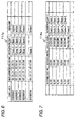
- the accumulated image list 117a is the list having the detailed information of the accumulated image accumulated in the accumulation memory 119.
- the list items may include the serial number, image generation date and time, distribution recipient IP, and camera name.
- Fig. 6 shows one example of the accumulated image list 117a.
- the serial number is the number describing the sequence starting from 1.
- the image generation date and time is the date and time when the image is accumulated in the accumulation memory 119.
- the distribution recipient IP is the IP address of the PC 120 of monitoring object for which the image sending monitoring section 116 monitors the distribution of the image at the time of accumulating the image.
- the camera name describes the camera name of the network camera 110 that accumulates the image among one or more network cameras 110.
- the schedule table 114a lists a schedule for one week in the network camera system 100, and has the items of the recording start time, recording end time, recording interval and distribution recipient IP.
- the schedule table 114a is stored in the temporary memory 114.
- the schedule table 114a may be created on the side of the network camera 110, or created on the side of the PC 120 and transmitted via the network 130 to the network camera 110.
- Fig. 7 shows one example of the schedule table 114a.
- the recording start time is the start time of the recording period indicting the time zone for accumulating the image when the distribution of image by the sending and receiving section 115 is interrupted during the monitoring of the image sending monitoring section 116.
- the recording end time is the end time of the recording period.
- the recording interval describes the time interval of accumulating the image in the accumulation memory 119.
- the distribution recipient IP describes the IP address of the PC 120 of monitoring object for which the image sending monitoring section 116 monitors the distribution of image.
- the methods for monitoring the distribution of image data include a method (client pull) where the PC 120 distributes a fixed amount of image data based on an image acquisition request at every fixed interval, and a method (server push) where the network camera 130 distributes the image data at a time upon one image acquisition request from the PC 120.
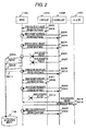
- Fig. 2 is an image distribution monitoring sequence chart in the client pull of the network camera system 100 according to the embodiment of the invention.
- the network camera system 100 comprises a server having one or more network cameras 110 and n (n is an integer of 1 or greater) clients having one or more PCs 120, in which the image acquisition request from the second client is only monitored.
- n is an integer of 1 or greater
- Each server and each client has the same configuration and functions. It is supposed that any one of the servers is a server 110A and n clients include a first client 120A, a second client 120B, .., and an nth client 120n.
- an image acquisition request is sent from the first client 120A to the server 110A, and detected by the server 114A (step S201), and the image is normally distributed from the server 110A to the first client 120A (step S202).
- an image acquisition request is sent from the second client 120B to the server 110A, and detected by the server 110A (step S203), and the image is normally distributed from the server 110A to the second client 120B (step S204).
- step S205 When the next image acquisition request is not detected within a preset time period in the server 110A though the image acquisition request is sent from the second client 120B to the server 110A (step S205), the server 110A starts to accumulate the image in the accumulation memory 119 because the image acquisition request from the second client 120A is monitored (step S206).
- ACK acknowledgement
- the second client 120B After the passage of a preset time t since not detecting the image acquisition request at step S205, the second client 120B sends the image acquisition request to the server 110A again (step S207). If the image acquisition request at step S207 is not detected within the preset time period in the server 110A. the image is subsequently accumulated in the accumulation memory 119 (step S208).
- an image acquisition request is sent from the second client 120B to the server 110A, and detected by the server 110A (step 5209), and the image is distributed from the server 110A to the second client 120B (step S210). Since the image acquisition request is normally detected at step S209, the accumulation of image in the accumulation memory 119 is stopped (step S211).
- step S211 when an image acquisition request is not detected within the preset time by the server 110A though the image acquisition request is sent from the first client 120A to the server 110A, the image is not accumulated in the accumulation memory 119 (step S211), because the image acquisition request from the second client 120B is not monitored.
- an image acquisition request is sent from the nth client 120n to the server 110A, and detected by the server 110A (step S213), and the image is normally distributed from the server 110A to the nth client 120n (step S214).
- the above is the image distribution monitoring procedure in the client pull.
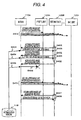
- Fig. 3 is an image distribution monitoring sequence chart in the server push of the network camera system 100 according to the embodiment of the invention.
- the network camera system 100 comprises the server 110A, the first client 120A, the second client 120B, .., and the nth client 120n, in which the distribution of image to the second client is only monitored.
- Each client has the same configuration and functions,
- an image distribution start request is sent from the first client 120A to the server 110A (step S301), and the image is distributed from the server 110A to the first client 120A, whereby the distribution of image is continued until the server 110A receives an image distribution stop request from the first client 120A, or until the distributed image is not normally received by the first client 120A (step S302).
- ACK is transmitted from the client to the server 110A, when the client normally receives the image, whereby the server 110A can know that the client normally receives the image.
- step S303 If the normal reception of image is not detected beyond a preset time white the image is distributed from the first client 120A to the server 110A, the image is not accumulated in the accumulation memory 119 because the first client 120A is the client out of the monitoring object (step S303).
- an image distribution start request is sent from the client 120B to the server 110A (step S304), and the image is distributed from the server 110A to the second client 120B, whereby the distribution of image is continued until the server 110A receives an image distribution stop request from the second client 120B, or until the distributed image is not normally received by the second client 120B (step S305).
- step S306 If the normal reception (ACK) of image is not detected beyond the preset time while the image is distributed from the second client 120B to the server 110A (step S306), the accumulation of image in the accumulation memory 119 is started because the second client 120B is the client of the monitoring object (step S307),
- step S306 the image is redistributed from the server 110A to the second client 120B at every set interval (S308). If the second client 120B can not detect the reception of image even though the image is redistributed, the accumulation of image in the accumulation memory 119 is continued (step S309). In Fig. 3 , the illustration is omitted, except for the first redistribution. This redistribution is performed until the second client 120B normally detects the reception of image, or for a preset period of time.
- step S310 when the second client 120B normally receives the image (step S310), the accumulation of image in the accumulation memory 119 is stopped (step S311). Thereafter, the distribution of image is continued until there is an image distribution stop request from the second client 120B or until the distributed image is not normally received by the second client 120B (step S312).
- step S313 If an image distribution stop request is sent from the second client 120B to the server 110A, and detected by the server 110A, the server 110A stops the distribution of image (step S313). Also, when an image distribution start request is sent from the nth client 120n to the server 110A (step S314), the image is distributed from the server 110A to the nth client 120n, whereby the distribution of image is continued until the server 110A receives an image distribution stop request from the nth client 120n, or until the distributed image is not normally received by the nth client 120n (step S315).
- the above is the image distribution monitoring procedure in the server push.
- Fig. 4 is a sequence chart for accumulated image existence notification and accumulated image acquisition in the network camera system 100 according to the embodiment of the invention.
- the network camera system 100 has the server 110A, the first client 120A, the second client 120B, .., and the nth client 120n, in which the second client acquires the accumulated image.
- the accumulated image list 117a listing the details of accumulated image accumulated in the server 110A is broadcast to each client 120A, 120B, .., 120n (step S401). This broadcast notification is made at every preset interval.
- the second client 120B recognizes the existence of the accumulated image by receiving the accumulated image list 117a, and transmits an accumulated image acquisition request to the server 110A in the time Zone where the second client 120B itself has a light load (step S402).
- the server 110A receives the accumulated image acquisition request, and distributes the accumulated image to the second client 120B by taking the accumulated image out of the accumulation memory 119 (step S403).
- the amount of accumulated image that can be distributed at a time is predetermined.
- the accumulated image after completion of transmission to the second client 120B is deleted from the accumulation memory 119 (step S404),
- step S405 If the distribution of the accumulated image in response to the accumulated image acquisition request at step S402 is not detected by the second client 120B (step S405), the accumulated image scheduled to transmit is not deleted from the accumulation memory 119, because the transmission of the accumulated image to the second client 120B is not completed (step S406).
- the second client 120B may send the accumulated image list acquisition request to the server 110A (step S407), and the server 110A may notify the accumulated image list 117a in response to it (step S408), for example.
- the timing at which the accumulation processing section 117 of the server 110A creates the accumulated image list 117a occurs when the accumulated image is stored into the accumulation memory in which the image is additionally written into the accumulated image list 117a, the accumulated image list acquisition request is received from each client in which the list of accumulated image in the accumulation memory 119 is created, or at every fixed time interval in which the accumulated image list 17a is updated.
- the above is the procedure for accumulated image existence notification and accumulated image acquisition.
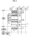
- Fig. 5 is a recording sequence chart based on the recording schedule of the network camera system 100 according to the embodiment of the invention.
- the recording schedule of Fig. 7 from Friday to Saturday will be described below.
- the network camera system 100 has the server 110A, the first client 120A, the second client 120B, .., and the nth client 120n.
- the recording start time is 8:30
- the recording end time is 22:00
- the recording interval is 6 seconds
- the distribution recipient IP is the first client 120A and the second client 120B on Friday, whereby the network camera system 100 starts to monitor the distribution of image to the first client 120A and the second client 120B at 8:30 on Friday.
- step S501 when an image acquisition request is sent from the second client 120B to the server 110A (step S501), the server 110A distributes the image to the second client 120B (step S502).
- the image acquisition request is sent at a fixed time interval.
- step S503 After the image acquisition request is sent from the second client 120B to the server 110A (step S501), when the second client 120B can not detect the distribution of image beyond a set time (step S503), the accumulation of image in the accumulation memory 119 is started (step S504).
- the image acquisition request is sent from the first client 120A to the server 110A (step S505), and the server 110A can distribute the image to the first client 120B, but when the distribution of image to the second client 120A is interrupted, the accumulation of image in the accumulation memory 119 is continued (step S507). Since the accumulation of image in the accumulation memory 119 is made at every recording interval, the image is accumulated at every six seconds here.
- step S508 If the image acquisition request is sent from the second client 120B to the server 190A (step S508), the second client 120B detects the distribution of accumulated image (step S509), the image acquisition request is sent from the first client 120 to the server 110A (step S510), and the first client 120A detects the distribution of accumulated image (step S511), that is, when the image can be distributed to both the first client 120A and the second client 120B of monitoring objects, the accumulation of image in the accumulation memory 119 is stopped (step S512).
- the image is not distributed from the server 110A to the nth client 120n (step S514).
- step S5 even when the image acquisition request is sent from the second client 1208 of monitoring object for image distribution to the server 110A (step S515), the image is not distributed from the server 110A to the second client 120B when the image acquisition request is out of the recording object period such as a time zone from 22:00 on Friday to 9:00 on Saturday (step S516).
- the recording procedure based on the recording schedule. In this way, it is possible to efficiently utilize the capacity of accumulation memory for the network camera on the server side by setting the recording period.
- the network camera system 100 connected to the network 130 comprises the network camera 190 and a plurality of PCs 120 to which the image is distributed from the network camera 110, and the network camera 110 comprises the image pickup section 111 for picking up the image, the sending and receiving section 115 for distributing the picked up image taken by the image pickup section 111 to the PC 120, the image sending monitoring section 116 for monitoring whether or not the picked up image is distributed to the designated PC 120 among the plurality of PCs 120 by the sending and receiving section 115, and the accumulation memory 119 for accumulating the picked up image when the distribution of image to the designated PC 120 by the sending and receiving section 115 is interrupted while being monitored by the image sending monitoring section 116, in which the PC 120 has the image receiving section 121 for receiving the picked up image distributed to the designated PC 120 by the sending and receiving section 115, whereby it is possible to securely distribute the image to the designated PC 120.
- the invention is effective for the network camera and the network camera system in which the image can be securely distributed to the designated distribution recipient.
Landscapes
- Engineering & Computer Science (AREA)
- Multimedia (AREA)
- Signal Processing (AREA)
- Databases & Information Systems (AREA)
- General Engineering & Computer Science (AREA)
- Closed-Circuit Television Systems (AREA)
- Two-Way Televisions, Distribution Of Moving Picture Or The Like (AREA)
- Studio Devices (AREA)
- Television Signal Processing For Recording (AREA)
Applications Claiming Priority (2)
| Application Number | Priority Date | Filing Date | Title |
|---|---|---|---|
| JP2005334548A JP4712537B2 (ja) | 2005-11-18 | 2005-11-18 | ネットワークカメラ、ネットワークカメラシステム、監視方法 |
| PCT/JP2006/322882 WO2007058269A1 (ja) | 2005-11-18 | 2006-11-16 | ネットワークカメラ、ネットワークカメラシステム、監視方法 |
Publications (1)
| Publication Number | Publication Date |
|---|---|
| EP1956843A1 true EP1956843A1 (en) | 2008-08-13 |
Family
ID=38048653
Family Applications (1)
| Application Number | Title | Priority Date | Filing Date |
|---|---|---|---|
| EP06832762A Withdrawn EP1956843A1 (en) | 2005-11-18 | 2006-11-16 | Network camera, network camera system, monitor method |
Country Status (5)
| Country | Link |
|---|---|
| US (1) | US9113065B2 (cg-RX-API-DMAC7.html) |
| EP (1) | EP1956843A1 (cg-RX-API-DMAC7.html) |
| JP (1) | JP4712537B2 (cg-RX-API-DMAC7.html) |
| CN (1) | CN101313571B (cg-RX-API-DMAC7.html) |
| WO (1) | WO2007058269A1 (cg-RX-API-DMAC7.html) |
Families Citing this family (6)
| Publication number | Priority date | Publication date | Assignee | Title |
|---|---|---|---|---|
| CN101742197B (zh) * | 2008-11-18 | 2012-10-03 | 华为技术有限公司 | 前端设备、录像文件备份方法及其控制方法、装置及系统 |
| JP5316550B2 (ja) * | 2011-01-05 | 2013-10-16 | 株式会社デンソー | 後方視界支援システム |
| EP2538672B1 (en) * | 2011-06-21 | 2020-08-12 | Axis AB | Method for configuring networked cameras |
| US20160142778A1 (en) * | 2013-06-28 | 2016-05-19 | Hitachi Industry & Control Solutions, Ltd. | Network camera, network camera control terminal, and video recording/delivering system |
| JP6249754B2 (ja) * | 2013-12-13 | 2017-12-20 | オリンパス株式会社 | 撮像装置、撮像システム、通信機器、撮像方法、及び撮像プログラム |
| EP3869813B1 (en) * | 2020-02-24 | 2022-03-30 | Axis AB | Streaming of a live video stream |
Family Cites Families (17)
| Publication number | Priority date | Publication date | Assignee | Title |
|---|---|---|---|---|
| JP4160118B2 (ja) * | 1996-06-28 | 2008-10-01 | ティー.エリック ホプキンス | 画像収集システム |
| JP4767443B2 (ja) * | 2001-07-04 | 2011-09-07 | 富士通株式会社 | ネットワーク蓄積型ビデオカメラシステム |
| CN2588705Y (zh) * | 2002-07-15 | 2003-11-26 | 李鹏 | 高安全网络摄像机 |
| JP2004147262A (ja) * | 2002-10-28 | 2004-05-20 | Matsushita Electric Ind Co Ltd | ネットワークカメラ装置およびカメラ映像配信方法 |
| JP4276452B2 (ja) * | 2003-02-18 | 2009-06-10 | パナソニック株式会社 | ネットワークカメラ |
| JP2004320642A (ja) * | 2003-04-18 | 2004-11-11 | Sumitomo Electric Ind Ltd | 動体通知方法、動体検出方法、撮像装置及び動体検出システム |
| JP4447860B2 (ja) * | 2003-06-30 | 2010-04-07 | ソニー株式会社 | ネットワークカメラ |
| US20060268122A1 (en) * | 2003-09-01 | 2006-11-30 | Mariko Iwasaki | Camera having transmission function, mobile telephone device, and image data acquiring/transmitting program |
| US20050052548A1 (en) * | 2003-09-09 | 2005-03-10 | Delaney Beth M. P. | Digital camera and method providing automatic image file backup during upload |
| CN2636533Y (zh) * | 2003-09-11 | 2004-08-25 | 上海复旦聚升信息科技有限公司 | 一种网络摄像机 |
| JP2005295255A (ja) * | 2004-03-31 | 2005-10-20 | Toshiba Corp | 撮像装置、及び撮像画像の送信方法 |
| JP2005339361A (ja) * | 2004-05-28 | 2005-12-08 | Fuji Photo Film Co Ltd | 画像表示装置および方法並びにプログラム |
| JP4535317B2 (ja) | 2004-05-31 | 2010-09-01 | 株式会社吉野工業所 | コンパクト容器 |
| US7698487B2 (en) * | 2004-06-30 | 2010-04-13 | Intel Corporation | Share resources and increase reliability in a server environment |
| HK1066447A2 (zh) * | 2004-09-14 | 2005-02-04 | 博视智能监控(香港)有限公司 | 用於數字監控系統的備份系統 |
| JP4914127B2 (ja) * | 2005-07-11 | 2012-04-11 | キヤノン株式会社 | ネットワークカメラ装置およびネットワークカメラ装置の映像フレームの送信方法 |
| US7877777B2 (en) * | 2006-06-23 | 2011-01-25 | Canon Kabushiki Kaisha | Network camera apparatus and distributing method of video frames |
-
2005
- 2005-11-18 JP JP2005334548A patent/JP4712537B2/ja not_active Expired - Fee Related
-
2006
- 2006-11-16 US US12/094,095 patent/US9113065B2/en active Active
- 2006-11-16 EP EP06832762A patent/EP1956843A1/en not_active Withdrawn
- 2006-11-16 WO PCT/JP2006/322882 patent/WO2007058269A1/ja not_active Ceased
- 2006-11-16 CN CN2006800431769A patent/CN101313571B/zh not_active Expired - Fee Related
Non-Patent Citations (1)
| Title |
|---|
| See references of WO2007058269A1 * |
Also Published As
| Publication number | Publication date |
|---|---|
| US20090174770A1 (en) | 2009-07-09 |
| JP2007142861A (ja) | 2007-06-07 |
| JP4712537B2 (ja) | 2011-06-29 |
| CN101313571A (zh) | 2008-11-26 |
| WO2007058269A1 (ja) | 2007-05-24 |
| CN101313571B (zh) | 2011-04-27 |
| US9113065B2 (en) | 2015-08-18 |
Similar Documents
| Publication | Publication Date | Title |
|---|---|---|
| US20090265462A1 (en) | Monitoring apparatus and storage method | |
| US20100033576A1 (en) | Data delivery device | |
| CN102843442A (zh) | 用于配置联网的照相机的方法 | |
| US20190132763A1 (en) | Method and device for transmitting data | |
| EP1956843A1 (en) | Network camera, network camera system, monitor method | |
| US10972546B2 (en) | Image processing system, connection mediation server, and recording medium | |
| US20100013634A1 (en) | Distributed systems monitoring system | |
| JP2007312028A (ja) | 監視画像送出装置およびプログラム | |
| US20080185772A1 (en) | Systems and methods for a graceful push handling user interface | |
| JPWO2006112176A1 (ja) | データ記録システム、データ取得装置、データ記録装置、データ取得装置制御プログラム、およびデータ記録装置制御プログラム | |
| JP2006195890A (ja) | 情報処理装置、システム、データ同期方法及びプログラム | |
| JPWO2018110047A1 (ja) | 中継装置 | |
| JP2007142861A5 (cg-RX-API-DMAC7.html) | ||
| EP3331184B1 (en) | Time shift retransmission system | |
| JP4573181B2 (ja) | モジュール配信方法、プログラム及び配信サーバ | |
| JP2007318411A (ja) | 画像監視装置、及び画像監視方法 | |
| JP6476995B2 (ja) | 中継装置、コンテンツ配信システム、中継方法およびプログラム | |
| EP1058423B1 (en) | Message delivery system | |
| JP4191653B2 (ja) | 画像取得システム、画像取得システムの制御方法及びプログラム | |
| JP4292073B2 (ja) | 映像管理装置 | |
| JP2005291772A (ja) | 電子機器装置およびその制御システム | |
| JP7195781B2 (ja) | 監視カメラシステム | |
| US9955063B2 (en) | Imaging system and imaging terminal | |
| JP2005005977A (ja) | 撮像システム | |
| JP2018098658A (ja) | 映像監視システム、監視カメラ及びモバイル端末 |
Legal Events
| Date | Code | Title | Description |
|---|---|---|---|
| PUAI | Public reference made under article 153(3) epc to a published international application that has entered the european phase |
Free format text: ORIGINAL CODE: 0009012 |
|
| 17P | Request for examination filed |
Effective date: 20080604 |
|
| AK | Designated contracting states |
Kind code of ref document: A1 Designated state(s): DE FR GB IT |
|
| RAP1 | Party data changed (applicant data changed or rights of an application transferred) |
Owner name: PANASONIC CORPORATION |
|
| RBV | Designated contracting states (corrected) |
Designated state(s): DE FR GB IT |
|
| DAX | Request for extension of the european patent (deleted) | ||
| STAA | Information on the status of an ep patent application or granted ep patent |
Free format text: STATUS: THE APPLICATION HAS BEEN WITHDRAWN |
|
| 18W | Application withdrawn |
Effective date: 20130214 |