EP1956149A1 - Schlauch, inbesondere Brauseschlauch, mit Umspritzung - Google Patents
Schlauch, inbesondere Brauseschlauch, mit Umspritzung Download PDFInfo
- Publication number
- EP1956149A1 EP1956149A1 EP07002616A EP07002616A EP1956149A1 EP 1956149 A1 EP1956149 A1 EP 1956149A1 EP 07002616 A EP07002616 A EP 07002616A EP 07002616 A EP07002616 A EP 07002616A EP 1956149 A1 EP1956149 A1 EP 1956149A1
- Authority
- EP
- European Patent Office
- Prior art keywords
- hose
- sleeve
- encapsulation
- inner tube
- metal spiral
- Prior art date
- Legal status (The legal status is an assumption and is not a legal conclusion. Google has not performed a legal analysis and makes no representation as to the accuracy of the status listed.)
- Granted
Links
- 238000007765 extrusion coating Methods 0.000 title abstract description 6
- 239000002184 metal Substances 0.000 claims abstract description 44
- 239000004033 plastic Substances 0.000 claims abstract description 16
- 229920003023 plastic Polymers 0.000 claims abstract description 16
- 238000005538 encapsulation Methods 0.000 claims description 36
- 239000000463 material Substances 0.000 claims description 12
- 239000011324 bead Substances 0.000 claims description 4
- 238000001125 extrusion Methods 0.000 claims 1
- 238000004519 manufacturing process Methods 0.000 description 2
- 230000015572 biosynthetic process Effects 0.000 description 1
- 238000002347 injection Methods 0.000 description 1
- 239000007924 injection Substances 0.000 description 1
- 230000035515 penetration Effects 0.000 description 1
- 238000002360 preparation method Methods 0.000 description 1
Images


Classifications
-
- F—MECHANICAL ENGINEERING; LIGHTING; HEATING; WEAPONS; BLASTING
- F16—ENGINEERING ELEMENTS AND UNITS; GENERAL MEASURES FOR PRODUCING AND MAINTAINING EFFECTIVE FUNCTIONING OF MACHINES OR INSTALLATIONS; THERMAL INSULATION IN GENERAL
- F16L—PIPES; JOINTS OR FITTINGS FOR PIPES; SUPPORTS FOR PIPES, CABLES OR PROTECTIVE TUBING; MEANS FOR THERMAL INSULATION IN GENERAL
- F16L33/00—Arrangements for connecting hoses to rigid members; Rigid hose connectors, i.e. single members engaging both hoses
- F16L33/01—Arrangements for connecting hoses to rigid members; Rigid hose connectors, i.e. single members engaging both hoses adapted for hoses having a multi-layer wall
-
- E—FIXED CONSTRUCTIONS
- E03—WATER SUPPLY; SEWERAGE
- E03C—DOMESTIC PLUMBING INSTALLATIONS FOR FRESH WATER OR WASTE WATER; SINKS
- E03C1/00—Domestic plumbing installations for fresh water or waste water; Sinks
- E03C1/02—Plumbing installations for fresh water
- E03C1/025—Water supply lines as such, e.g. shower hoses
-
- F—MECHANICAL ENGINEERING; LIGHTING; HEATING; WEAPONS; BLASTING
- F16—ENGINEERING ELEMENTS AND UNITS; GENERAL MEASURES FOR PRODUCING AND MAINTAINING EFFECTIVE FUNCTIONING OF MACHINES OR INSTALLATIONS; THERMAL INSULATION IN GENERAL
- F16L—PIPES; JOINTS OR FITTINGS FOR PIPES; SUPPORTS FOR PIPES, CABLES OR PROTECTIVE TUBING; MEANS FOR THERMAL INSULATION IN GENERAL
- F16L11/00—Hoses, i.e. flexible pipes
- F16L11/14—Hoses, i.e. flexible pipes made of rigid material, e.g. metal or hard plastics
- F16L11/16—Hoses, i.e. flexible pipes made of rigid material, e.g. metal or hard plastics wound from profiled strips or bands
-
- F—MECHANICAL ENGINEERING; LIGHTING; HEATING; WEAPONS; BLASTING
- F16—ENGINEERING ELEMENTS AND UNITS; GENERAL MEASURES FOR PRODUCING AND MAINTAINING EFFECTIVE FUNCTIONING OF MACHINES OR INSTALLATIONS; THERMAL INSULATION IN GENERAL
- F16L—PIPES; JOINTS OR FITTINGS FOR PIPES; SUPPORTS FOR PIPES, CABLES OR PROTECTIVE TUBING; MEANS FOR THERMAL INSULATION IN GENERAL
- F16L33/00—Arrangements for connecting hoses to rigid members; Rigid hose connectors, i.e. single members engaging both hoses
- F16L33/34—Arrangements for connecting hoses to rigid members; Rigid hose connectors, i.e. single members engaging both hoses with bonding obtained by vulcanisation, gluing, melting, or the like
Definitions
- the sleeve may have an external thread with which it is screwed into passages of the metal spiral in order to achieve firm bonding between the metal spiral and the sleeve.
- a screw can be made of plastic as well as metal.
- the sleeve has a collar that can be overlapped by a union nut.
- This collar advantageous to a collar of the connector on.
- the tube may have a further sleeve, which advantageously surrounds the encapsulation.
- This further sleeve can be made of metal.
- Such a further metal sleeve can convey a visually superior impression of the hose.
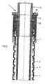
- All hoses 1 have in common that they are constructed in three layers. They have an inner tube 2, which is loosely retracted in a metal spiral 3. The metal spiral 3 is surrounded by a jacket 4. The sheath 4 penetrates partially into the grooves or passages of the spiral.
- the inner tube 2 projects slightly beyond the metal spiral 3 and the casing 4 at the ends.
- an encapsulation 6 is provided on the outside of the inner tube or the sleeve 7 surrounding the inner tube in this region.
- This encapsulation 6 surrounds the sleeve 7 in this area and also surrounds the end region of the metal spiral 3 and the casing 4.
- the encapsulation forms a material connection with the casing 4.
- the sleeve 7 of the first tube is made of metal.
- the encapsulation 6 has on the inside two circumferential beads on which the sleeve 7 sealingly abut with areas 71, so no moisture in the space between the metal spiral 3 and the inner tube 2 can penetrate.
- the encapsulation 6 engages behind Furthermore, the sheath 4 and the metal spiral 3. This ensures a tight fit of the encapsulation at the end of the hose.
- the in- FIG. 4 illustrated fourth hose 1 differs from the first hose according to FIG. 1 essentially in that, instead of the sleeve 7 made of metal, a sleeve 7 made of plastic is provided. This sleeve 7 also has - as the sleeve 7 of the third tube - an external thread, which is screwed into the metal spiral 3.
Abstract
Description
- Die vorliegende Erfindung betrifft einen Schlauch, insbesondere einen Brauseschlauch mit einem Innenschlauch, einer Metallspirale, einer Ummantelung, einem Anschlussstück und einer Umspritzung, wobei das Anschlussstück in den Innenschlauch eingepresst ist, der Innenschlauch in der Metallspirale angeordnet ist, die Metallspirale mit der Ummantelung versehen ist und die Umspritzung (6) an die Ummantelung (4) angespritzt ist
- Ein Schlauch der eingangsgenannten Art ist aus der Gebrauchsmusterschrift mit der Veröffentlichungsnummer
DE 202 11 150 U1 bekannt. Das Anschlussteil des Schlauchs ist aus einem Kunststoff hergestellt und mit dem Kunststoffinnenschlauch verschweißt. Außerdem übergreift das Anschlussstück die äußere Kunststoffummantelung der Metallspirale. Die Umspritzung und das Anschlussstück sind einstückig ausgeführt, das heißt, das Anschlussstück ist als Umspritzung des Innenschlauchs beziehungsweise der Ummantelung vorgesehen. - Ein derartiges angespitztes Anschlussstück ist vorteilhaft bei der Herstellung des Schlauches. Außerdem greifen keine den Schlauch verengenden Teile in das Innere des Innenschlauchs ein. Zu dem bietet die Umspritzung einen Schutz gegen das Eindringen von Feuchtigkeit in den Zwischenraum zwischen dem Innenschlauch und der Metallspirale.
- Ein Anspritzen des Anschlussstücks an den Innenschlauch ist zur möglich, wenn das Kunststoffmaterial des Innenschlauch und des Anschlussstück auf einander abgestimmt sind. Diese hat zur Folge, das man bei der Fertigung des Schlauchs besonders auf die Materialwahl achten muss. Man kann daher u. U. für das Anschlussstück bzw. für den Innenschlauch nicht immer das für seine Funktion geeignet Material wählen, sondern muss aufgrund der erforderlichen Kombinierbarkeit mit dem andern Teil Kompromisse eingehen.
- Ein weiterer Nachteil ist die geringere Zugfestigkeit eines solchen Schlauches. Zugkräfte, die über das Anschlussstücke in den Schlauch eingeleitet werden, werden über den in der Regel nicht auf Zugfestigkeit ausgelegten Innenschlauch übertragen. Dieses kann Schäden an dem Innenschlauch führen.
- Vor dem Hintergrund des Standes der Technik lag der Erfindung die Aufgabe zugrunde einen Schlauch der eingangs genannten Art so fortzubilden, dass zum Einen eine hinreichende Zugfestigkeit gewährleistet und zum Anderen eine freiere Kombination von Kunststoffen möglich ist.
- Diese Aufgabe wird erfindungsgemäß dadurch gelöst, dass der Schlauch eine Hülse aufweist und dass die Umspritzung an der Hülse, diese zumindest teilweise umgreifend anliegt Der Innenschlauch kann in so in die Hülse eingezogen sein, dass der Innenschlauch zwischen dem in den Innenschlauch hineinragenden Teil des Anschlussstückes und der Hülse eingepresst ist. Die Hülse ist dazu vorteilhaft vor dem Einziehen des Schlauches in die Metallspirale eingebracht und mit dieser formschlüssig verbunden. Diese Art der Verbindung hat sich in der Vergangenheit als zuverlässig und hinreichend auszugsfest erwiesen. Durch die Umspritzung der Ummantelung, ist ferner ein Eindringen von Feuchtigkeit in den Zwischenraum zwischen der Metallspirale und der Ummantelung verhindert.
- Gemäß der Erfindung kann die Ummantelung aus einem Kunststoff hergestellt sein. Dieses ist insbesondere dann sinnvoll, wenn eine stoffliche Verbindung zwischen der Ummantelung und der Umspritzung hergestellt werden soll.
- Die Hülse, welche den Innenschlauch umgreift, kann aus Metall oder Kunststoff hergestellt sein. Es ist vorteilhaft wenn die Hülse aus Kunststoff hergestellt ist, weil dann eine stoffliche Verbindung zwischen der Umspritzung und der Hülse erreicht werden kann, die ein Eindringen von Feuchtigkeit an dieser Stelle in den Zwischenraum zwischen der Metallspirale und dem Innenschlauch verhindert. Die Hülse kann vorteilhaft zusammen mit der Umspritzung angespritzt werden.
- Die Hülse kann ein Außengewinde aufweisen, mit welchem sie in Gänge der Metallspirale eingeschraubt ist, um feste Bindung zwischen der Metallspirale und der Hülse zu erreichen. Eine solche Schraubhülse kann sowohl aus Kunststoff als auch aus Metall hergestellt sein.
- Vorteilhaft hat die Hülse einen Kragen, der von einer Überwurfmutter übergriffen werden kann. Dieser Kragen vorteilhaft an einem Kragen des Anschlussstücks an.
- Gemäß der Erfindung kann die Umspritzung die Metallspirale und/oder die Ummantelung hintergreifen, um einen festen Sitz der Umspritzung insbesondere bei fehlender stofflicher Verbindung mit der Ummantelung oder der Hülse zu erreichen.
- Die Umspritzung kann auf der Innenseite Wülste aufweisen, welche dichtend an Hülse anliegen können.
- Der Schlauch kann eine weitere Hülse aufweisen, welche vorteilhaft die Umspritzung umgreift. Diese weitere Hülse kann aus Metall hergestellt sein. Eine derartige weitere Metallhülse kann einen optisch höherwertigen Eindruck des Schlauches vermitteln.
- Das Anschlussstück kann eine Nut aufweisen, in welche die Umspritzung eingreift. Die weitere Hülse umgreift dann vorteilhaft das in die Nut eingreifende Material der Umspritzung, um ggf. ein herausfließen des Materials der Umspritzung aus der Nute zu verhindern.
- Der Innenschlauch kann sowohl die Metallspirale als auch die Ummantelung der Metallspirale überragen.
- Ausführungsbeispiele für erfindungsgemäße Brauseschläuche sind anhand der Zeichnungen näher erläutert.
- Es zeigt:
- Fig. 1
- Einen Längsschnitt durch das Ende eines ersten Schlauches
- Fig. 2
- Einen Längsschnitt durch das Ende eines zweiten Schlauches,
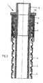
- Fig. 3
- einen Längsschnitt durch das Ende eines dritten Schlauches
- Fig. 4
- einen Längsschnitt durch das Ende eines vierten Schlauches und
- Fig. 5
- einen Längsschnitt durch das Ende eines fünften Schlauches.
- Bevor zu den in den Figuren dargestellten Schläuchen 1 die Unterschiede erläutert werden, werden zunächst die Gemeinsamkeiten der Schläuche 1 erläutert.
- Allen Schläuchen 1 ist gemeinsam, dass sie dreilagig aufgebaut sind. Sie weisen einen Innenschlauch 2 auf, der in einer Metallspirale 3 lose eingezogen ist. Die Metallspirale 3 ist mit einer Ummantelung 4 umgeben. Die Ummantelung 4 dringt teilweise in die Rillen oder Gänge der Spirale ein.
- An zumindest einem Ende des Schlauches weist der Schlauch 1 jeweils ein Anschlussstück 5 auf. Die Anschlussstücke 5 sind in Form von Einpressnippeln eingeführt, die in dem Innenschlauch 2 eingepresst sind. Tannenbaumstrukturen dringen dabei von der Innenseite in die innere Oberfläche des Innenschlauches 2 ein. In dem Endbereich, in welchen die Anschlussstücke 5 eingepresst sind, ist der Innenschlauch von einer Hülse 7 umgeben. Zwischen dem Innenschlauch 2, der Hülse 7 und dem Anschlussstück 5 ist eine Pressverbindung hergestellt. Damit ist eine auszugsichere Befestigung des Anschlussstücks an dem Innenschlauch gewährleistet.
- Der Innenschlauch 2 überragt an den Enden die Metallspirale 3 und die Ummantelung 4 geringfügig, In dem die Metallspirale 3 und die Ummantelung 4 überragenden Bereich ist auf der Außenseite des Innenschlauchs beziehungsweise der in diesem Bereich den Innenschlauch umgebenden Hülse 7 eine Umspritzung 6 vorgesehen. Diese Umspritzung 6 umgreift in diesem Bereich die Hülse 7 und umgreift außerdem den Endbereich der Metallspirale 3 und der Ummantelung 4. Die Umspritzung geht eine stoffliche Verbindung mit der Ummantelung 4 ein.
- Das Ende des Innenschlauches 2 stößt in den Ausführungsbeispielen der
Fig. 1 bis 3 an einen umlaufenden Bund oder Kragen des Anschlussstückes 5 an. Bei den Ausführungsbeispielen derFiguren 4 und5 ist das Ende des Innenschlauches beabstandet von dem Bund bzw. Kragen. Auch ein Kragen der Hülse 7 liegt an dem Bund bzw. Kragen des Anschlussstückes 5 an. - Die Hülse 7 des ersten Schlauchs ist aus Metall hergestellt.
Die Umspritzung 6 weist auf der Innenseite zwei umlaufende Wülste auf, an denen die Hülse 7 mit Bereichen 71 dichtend anliegen, so keine Feuchtigkeit in den Raum zwischen der Metallspirale 3 und dem Innenschlauch 2 eindringen kann. Die Umspritzung 6 hintergreift ferner die Ummantelung 4 und die Metallspirale 3. Dadurch ist ein fester Sitz der Umspritzung an dem Endbereich des Schlauches gewährleistet. - Zur Herstellung des Schlauch 1 gemäß
Figur 1 wird zunächst die Metallspirale 3 mit der Ummantelung 4 versehen. Anschließend wird die Umspritzung 6 angeformt. Dann wird die Metallhülse 7 eingesteckt und durch Aufweiten formschlüssig mit dem Gebilde aus Metallspirale 3, Ummantelung 4 und Umspritzung 6 formschlüssig verbunden. Im nächsten Schritt wird der Innenschlauch 2 in die Metallspirale 3 eingezogen und das Anschlussstück 5 eingepresst. Zum Schluss wird die weitere Hülse 8 über die Umspritzung 6 gezogen. - Eine weitere Hülse 8, die auch bei den übrigen Schläuchen gemäß der
Figuren 2 und3 vorgesehen ist, schließt die Ummantelung 6 im im Außenbereich ab. - Der zweite Schlauch und der dritte Schlauch sind so ausgestaltet, dass das Anschlussstück einen weiteren Kragen aufweist. Zwischen diesem weiteren Kragen und dem ersten Kragen ist eine Nut ausgebildet, in welche die Umspritzung 6 eingreift. Die Umspritzung 6 geht damit eine formschlüssige und vorteilhaft auch eine stoffliche Verbindung mit dem Anschlussstück 5 ein. Die weitere Hülse 8 übergreift die Nut des Anschlussstücks 5, um eine herausrutschen der in die Nut eingreifenden Umspritzung aus der Nut zu verhindern.
- Während bei dem zweiten Schlauch gemäß
Figur 2 die Hülse 7, die zur festen Verbindung des Anschlussstückes 5 mit dem Innenschlauch 2 dient, wie bei dem ersten Schlauch gemäßFigur 1 aus Metall hergestellt ist, ist bei dem dritten Schlauch gemäßFigur 3 die Hülse 7 aus Kunststoff hergestellt. Diese Kunststoffhülse 7 weist auf der Außenseite eine Gwindestruktur auf, welche die gleiche Steigung hat wie die Metallspirale 3 und in innenseitige Gänge der Metallspirale 3 eingreift. Auch die Kunststoffhülse 7 ist so ausgebildet, dass sie vorteilhaft eine stoffliche Verbindung mit der Umspritzung 6 eingeht. - Der in-
Figur 4 dargestellt vierte Schlauch 1 unterscheidet sich von dem ersten Schlauch gemäßFigur 1 im Wesentlichen dadurch, dass anstelle der Hülse 7 aus Metall eine Hülse 7 aus Kunststoff vorgesehen ist. Diese Hülse 7 weist ebenfalls - wie die Hülse 7 des dritten Schlauchs - ein Außengewinde auf, weiches in die Metallspirale 3 eingeschraubt ist. - Bei fünften Schlauch gemäß
Figur 5 ist dagegen die Hülse 7 und die Umspritzung 6 einstückig ausgeführt, d. h. die Hülse 7 und die Umspritzung 6 sind in einem Arbeitsgang an die Metallspirale 3 und die Ummantelung 4 angespritzt worden.
Claims (14)
- Schlauch (1), insbesondere Brauseschlauch mit einem Innenschlauch (2), einer Metallspirale (3), einer Ummantelung (4), einem Anschlussstück (5) und einer Umspritzung (6), wobei- das Anschlussstück (5) in den Innenschlauch (2) eingepresst ist,- der Innenschlauch (2) in der Metallspirale (3) angeordnet ist.- die Metallspirale (3) mit der Ummantelung (4) versehen ist und- die Umspritzung (6) an die Ummantelung (4) angespritzt istdadurch gekennzeichnet,- dass der Schlauch (1) eine Hülse (7) aufweist, und- dass die Umspritzung (6) an der Hülse (7), diese zumindest teilweise umgreifend anliegt.
- Schlauch (1) nach Anspruch 1, dadurch gekennzeichnet, dass die Ummantelung (4) aus Kunststoff besteht.
- Schlauch (1) nach Anspruch 2, dadurch gekennzeichnet, dass die Ummantelung (4) stofflich mit der Umspritzung (6) verbunden ist.
- Schlauch (1) nach einem der Ansprüche 1 bis 3, dadurch gekennzeichnet, dass die Hülse (7) aus Metall besteht.
- Schlauch (1) nach einem der Ansprüche 1 bis 3, dadurch gekennzeichnet, dass die Hülse (7) aus Kunststoff besteht.
- Schlauch (1) nach Anspruch 5, dadurch gekennzeichnet, dass die Hülse (7) stofflich mit der Umspritzung (6) verbunden ist.
- Schlauch (1) nach einem der Ansprüche 1 bis 6, dadurch gekennzeichnet, dass die Hülse (7) ein Außengewinde hat, mit welchem sie in Gänge der Metallspirale (3) eingeschraubt ist.
- Schlauch (1) nach einem der Ansprüche 1 bis 7, dadurch gekennzeichnet, dass die Umspritzung (6) die Metallspirale (3) und/oder die Ummantelung (4) hintergreift.
- Schlauch (1) nach einem der Ansprüche 1 bis 8, dadurch gekennzeichnet, dass die Umspritzung (6) innenseitig Wülste (61) aufweist.
- Schlauch (1) nach Anspruch 9, dadurch gekennzeichnet, dass die Wülste (61) der Umspritzung (6) an der Außenfläche der Hülse (7) dichtend anliegen.
- Schlauch (1) nach einem der Ansprüche 1 bis 10, dadurch gekennzeichnet, dass das Anschlussstück (5) eine oder mehrere Nuten (51) aufweist.
- Schlauch (1) nach Anspruch 10, dadurch gekennzeichnet, dass die Umspritzung (6) in die Nut (51) des Anschlussstücks (5) eingreift.
- Schlauch (1) nach einem der Ansprüche 1 bis 11, dadurch gekennzeichnet, dass der Schlauch eine weitere Hülse (8) aufweist.
- Schlauch (1) nach einem der Ansprüche 1 bis 12 dadurch gekennzeichnet, dass der Innenschlauch (2) die Metallspirale (3) und/oder die Ummantelung (4) überragt.
Priority Applications (5)
| Application Number | Priority Date | Filing Date | Title |
|---|---|---|---|
| ES07002616T ES2354573T3 (es) | 2007-02-07 | 2007-02-07 | Manga, especialmente manga de ducha, con revestimiento inyectado. |
| AT07002616T ATE484634T1 (de) | 2007-02-07 | 2007-02-07 | Schlauch, inbesondere brauseschlauch, mit umspritzung |
| DE502007005334T DE502007005334D1 (de) | 2007-02-07 | 2007-02-07 | Schlauch, inbesondere Brauseschlauch, mit Umspritzung |
| EP07002616A EP1956149B1 (de) | 2007-02-07 | 2007-02-07 | Schlauch, inbesondere Brauseschlauch, mit Umspritzung |
| DE202007019213U DE202007019213U1 (de) | 2007-02-07 | 2007-02-07 | Schlauch, insbesondere Brauseschlauch mit Umspritzung |
Applications Claiming Priority (1)
| Application Number | Priority Date | Filing Date | Title |
|---|---|---|---|
| EP07002616A EP1956149B1 (de) | 2007-02-07 | 2007-02-07 | Schlauch, inbesondere Brauseschlauch, mit Umspritzung |
Publications (2)
| Publication Number | Publication Date |
|---|---|
| EP1956149A1 true EP1956149A1 (de) | 2008-08-13 |
| EP1956149B1 EP1956149B1 (de) | 2010-10-13 |
Family
ID=37983333
Family Applications (1)
| Application Number | Title | Priority Date | Filing Date |
|---|---|---|---|
| EP07002616A Active EP1956149B1 (de) | 2007-02-07 | 2007-02-07 | Schlauch, inbesondere Brauseschlauch, mit Umspritzung |
Country Status (4)
| Country | Link |
|---|---|
| EP (1) | EP1956149B1 (de) |
| AT (1) | ATE484634T1 (de) |
| DE (2) | DE502007005334D1 (de) |
| ES (1) | ES2354573T3 (de) |
Cited By (4)
| Publication number | Priority date | Publication date | Assignee | Title |
|---|---|---|---|---|
| DE102010007739B3 (de) * | 2010-02-12 | 2011-07-07 | Schmitz, Hartmut, 57072 | Auskleidung einer Schlauch- oder Rohrleitung |
| EP2716824A2 (de) | 2012-10-02 | 2014-04-09 | Witzenmann GmbH | Schlauch, insbesondere Brauseschlauch |
| EP3012502A1 (de) * | 2014-10-22 | 2016-04-27 | Witzenmann GmbH | Schlauch und anschlussvorrichtung für einen schlauch |
| WO2021224325A3 (de) * | 2020-05-05 | 2021-12-30 | Neoperl Gmbh | Schlauch, schlauchanordnung und korrespondierendes verfahren zur herstellung einer schlauchanordnung |
Citations (5)
| Publication number | Priority date | Publication date | Assignee | Title |
|---|---|---|---|---|
| US3467764A (en) | 1968-08-01 | 1969-09-16 | Transportgummi Veb | Heat and corrosion resistant hose coupling for supplying fuel,oil and the like |
| DE29506835U1 (de) * | 1994-07-19 | 1995-07-13 | Friedhelm Ramspott Metall Und | Anschlußstück für einen Kunststoffschlauch einer Badezimmer-Handbrause |
| US6106027A (en) * | 1998-04-09 | 2000-08-22 | Mulvey; Philip A. | Pull-out faucet hose |
| DE20211150U1 (de) | 2002-07-23 | 2002-09-26 | Vohran Patentverwertungs Gmbh | Schlauch, insbesondere Sanitärschlauch |
| DE20212169U1 (de) * | 2002-08-08 | 2002-11-14 | Friedhelm Ramspott Metall Und | Brauseschlauch |
-
2007
- 2007-02-07 AT AT07002616T patent/ATE484634T1/de active
- 2007-02-07 EP EP07002616A patent/EP1956149B1/de active Active
- 2007-02-07 DE DE502007005334T patent/DE502007005334D1/de active Active
- 2007-02-07 DE DE202007019213U patent/DE202007019213U1/de not_active Expired - Lifetime
- 2007-02-07 ES ES07002616T patent/ES2354573T3/es active Active
Patent Citations (5)
| Publication number | Priority date | Publication date | Assignee | Title |
|---|---|---|---|---|
| US3467764A (en) | 1968-08-01 | 1969-09-16 | Transportgummi Veb | Heat and corrosion resistant hose coupling for supplying fuel,oil and the like |
| DE29506835U1 (de) * | 1994-07-19 | 1995-07-13 | Friedhelm Ramspott Metall Und | Anschlußstück für einen Kunststoffschlauch einer Badezimmer-Handbrause |
| US6106027A (en) * | 1998-04-09 | 2000-08-22 | Mulvey; Philip A. | Pull-out faucet hose |
| DE20211150U1 (de) | 2002-07-23 | 2002-09-26 | Vohran Patentverwertungs Gmbh | Schlauch, insbesondere Sanitärschlauch |
| DE20212169U1 (de) * | 2002-08-08 | 2002-11-14 | Friedhelm Ramspott Metall Und | Brauseschlauch |
Cited By (6)
| Publication number | Priority date | Publication date | Assignee | Title |
|---|---|---|---|---|
| DE102010007739B3 (de) * | 2010-02-12 | 2011-07-07 | Schmitz, Hartmut, 57072 | Auskleidung einer Schlauch- oder Rohrleitung |
| EP2716824A2 (de) | 2012-10-02 | 2014-04-09 | Witzenmann GmbH | Schlauch, insbesondere Brauseschlauch |
| DE102012218036A1 (de) | 2012-10-02 | 2014-06-12 | Witzenmann Gmbh | Schlauch, insbesondere Brauseschlauch |
| EP2716824A3 (de) * | 2012-10-02 | 2015-03-18 | Witzenmann GmbH | Schlauch, insbesondere Brauseschlauch |
| EP3012502A1 (de) * | 2014-10-22 | 2016-04-27 | Witzenmann GmbH | Schlauch und anschlussvorrichtung für einen schlauch |
| WO2021224325A3 (de) * | 2020-05-05 | 2021-12-30 | Neoperl Gmbh | Schlauch, schlauchanordnung und korrespondierendes verfahren zur herstellung einer schlauchanordnung |
Also Published As
| Publication number | Publication date |
|---|---|
| DE502007005334D1 (de) | 2010-11-25 |
| ES2354573T3 (es) | 2011-03-16 |
| EP1956149B1 (de) | 2010-10-13 |
| DE202007019213U1 (de) | 2011-03-03 |
| ATE484634T1 (de) | 2010-10-15 |
Similar Documents
| Publication | Publication Date | Title |
|---|---|---|
| DE602005005150T2 (de) | Anschlussstutzen für Wellrohre und Rohr mit entsprechendem Stutzen | |
| DE2726962A1 (de) | Vorrichtung zum aufbereiten von thermoplastischen kunststoffen | |
| DE1943167B2 (de) | Schlauch mit mindestens zwei Schichten und einer Verstärkungslage zur Verbindung mit einer einen außen gezahnten Rohrstutzen aufweisenden Kupplung | |
| DE1775882A1 (de) | Flexibler Schlauch | |
| EP1956149B1 (de) | Schlauch, inbesondere Brauseschlauch, mit Umspritzung | |
| DE4034953C2 (de) | Rohrverbund aus Betonverbundrohren mit einem als Ummantelung dienenden Betonrohr und einem als Innenauskleidung des Betonrohres dienenden Kunststoffrohr | |
| EP0318636A1 (de) | Schlauch | |
| DE19523639A1 (de) | Schutzschlauch für Leitungen | |
| EP1179649B1 (de) | Injektionsbefestigungsanker | |
| DE102006049679B4 (de) | Fahrzeugtür mit Dichtebene und einem Dichtelement, dessen Enden sich überlappen | |
| EP0877191B1 (de) | Anschlussmuffe für einen mit einer Schutzhülle für zugentlastete elektrische Leiter versehenen Schlauch | |
| DE2151506C2 (de) | Flexibler Bremsschlauch | |
| DE102007033634B4 (de) | Kabeldurchführung für wenigstens ein elektrisches Kabel durch eine Wandung | |
| EP3211283B1 (de) | Schlauch und sanitärschlauch mit einem solchen schlauch und einem schlauchanschluss | |
| EP0950846B1 (de) | Leitungssystem | |
| DE19511469C1 (de) | Patientenkonnektor | |
| EP0060513A1 (de) | Brauseschlauch | |
| DE202005019120U1 (de) | Verbindungsanordnung zum Anbinden eines Faserverbund-Kunststoffrohres an ein weiterführendes Bauteil | |
| DE102011105715A1 (de) | Verbindungsanordnung | |
| DE2359459A1 (de) | Verbesserte, elektrisch isolierte bohrfutter | |
| DE102009024257B4 (de) | Vorrichtung zum Antreiben eines Behanges eines Sonnenschutzes oder eines Rollladens | |
| CH696553A5 (de) | Verbindungs- und Anschlussstück für Wellrohre. | |
| EP1262704B1 (de) | Muffe zum Koppeln von Mehrkanalrohren | |
| DE3941413C1 (en) | Joint for underground ventilation ducts - has hose fitted to inside of pipe at area of joint | |
| DE102005033391B4 (de) | Kabelabdichtungshülse |
Legal Events
| Date | Code | Title | Description |
|---|---|---|---|
| PUAI | Public reference made under article 153(3) epc to a published international application that has entered the european phase |
Free format text: ORIGINAL CODE: 0009012 |
|
| AK | Designated contracting states |
Kind code of ref document: A1 Designated state(s): AT BE BG CH CY CZ DE DK EE ES FI FR GB GR HU IE IS IT LI LT LU LV MC NL PL PT RO SE SI SK TR |
|
| AX | Request for extension of the european patent |
Extension state: AL BA HR MK RS |
|
| 17P | Request for examination filed |
Effective date: 20080912 |
|
| 17Q | First examination report despatched |
Effective date: 20081009 |
|
| AKX | Designation fees paid |
Designated state(s): AT BE BG CH CY CZ DE DK EE ES FI FR GB GR HU IE IS IT LI LT LU LV MC NL PL PT RO SE SI SK TR |
|
| GRAP | Despatch of communication of intention to grant a patent |
Free format text: ORIGINAL CODE: EPIDOSNIGR1 |
|
| GRAS | Grant fee paid |
Free format text: ORIGINAL CODE: EPIDOSNIGR3 |
|
| GRAA | (expected) grant |
Free format text: ORIGINAL CODE: 0009210 |
|
| RTI1 | Title (correction) |
Free format text: HOSE, IN PARTICULAR SHOWER HOSE, WITH INJECTION-MOULDED COATING |
|
| AK | Designated contracting states |
Kind code of ref document: B1 Designated state(s): AT BE BG CH CY CZ DE DK EE ES FI FR GB GR HU IE IS IT LI LT LU LV MC NL PL PT RO SE SI SK TR |
|
| REG | Reference to a national code |
Ref country code: GB Ref legal event code: FG4D Free format text: NOT ENGLISH |
|
| REG | Reference to a national code |
Ref country code: CH Ref legal event code: EP |
|
| REG | Reference to a national code |
Ref country code: IE Ref legal event code: FG4D Free format text: LANGUAGE OF EP DOCUMENT: GERMAN |
|
| REF | Corresponds to: |
Ref document number: 502007005334 Country of ref document: DE Date of ref document: 20101125 Kind code of ref document: P |
|
| REG | Reference to a national code |
Ref country code: NL Ref legal event code: T3 |
|
| REG | Reference to a national code |
Ref country code: DE Ref legal event code: R138 Ref document number: 202007019213 Country of ref document: DE Free format text: GERMAN DOCUMENT NUMBER IS 502007005334 Ref country code: DE Ref legal event code: R138 Ref document number: 502007005334 Country of ref document: DE Free format text: GERMAN DOCUMENT NUMBER IS 502007005334 |
|
| REG | Reference to a national code |
Ref country code: ES Ref legal event code: FG2A Effective date: 20110304 |
|
| LTIE | Lt: invalidation of european patent or patent extension |
Effective date: 20101013 |
|
| PG25 | Lapsed in a contracting state [announced via postgrant information from national office to epo] |
Ref country code: LT Free format text: LAPSE BECAUSE OF FAILURE TO SUBMIT A TRANSLATION OF THE DESCRIPTION OR TO PAY THE FEE WITHIN THE PRESCRIBED TIME-LIMIT Effective date: 20101013 |
|
| REG | Reference to a national code |
Ref country code: IE Ref legal event code: FD4D |
|
| PG25 | Lapsed in a contracting state [announced via postgrant information from national office to epo] |
Ref country code: BG Free format text: LAPSE BECAUSE OF FAILURE TO SUBMIT A TRANSLATION OF THE DESCRIPTION OR TO PAY THE FEE WITHIN THE PRESCRIBED TIME-LIMIT Effective date: 20110113 Ref country code: SI Free format text: LAPSE BECAUSE OF FAILURE TO SUBMIT A TRANSLATION OF THE DESCRIPTION OR TO PAY THE FEE WITHIN THE PRESCRIBED TIME-LIMIT Effective date: 20101013 Ref country code: SE Free format text: LAPSE BECAUSE OF FAILURE TO SUBMIT A TRANSLATION OF THE DESCRIPTION OR TO PAY THE FEE WITHIN THE PRESCRIBED TIME-LIMIT Effective date: 20101013 Ref country code: IS Free format text: LAPSE BECAUSE OF FAILURE TO SUBMIT A TRANSLATION OF THE DESCRIPTION OR TO PAY THE FEE WITHIN THE PRESCRIBED TIME-LIMIT Effective date: 20110213 Ref country code: PT Free format text: LAPSE BECAUSE OF FAILURE TO SUBMIT A TRANSLATION OF THE DESCRIPTION OR TO PAY THE FEE WITHIN THE PRESCRIBED TIME-LIMIT Effective date: 20110214 Ref country code: LV Free format text: LAPSE BECAUSE OF FAILURE TO SUBMIT A TRANSLATION OF THE DESCRIPTION OR TO PAY THE FEE WITHIN THE PRESCRIBED TIME-LIMIT Effective date: 20101013 Ref country code: FI Free format text: LAPSE BECAUSE OF FAILURE TO SUBMIT A TRANSLATION OF THE DESCRIPTION OR TO PAY THE FEE WITHIN THE PRESCRIBED TIME-LIMIT Effective date: 20101013 |
|
| PGFP | Annual fee paid to national office [announced via postgrant information from national office to epo] |
Ref country code: NL Payment date: 20110216 Year of fee payment: 5 |
|
| PG25 | Lapsed in a contracting state [announced via postgrant information from national office to epo] |
Ref country code: GR Free format text: LAPSE BECAUSE OF FAILURE TO SUBMIT A TRANSLATION OF THE DESCRIPTION OR TO PAY THE FEE WITHIN THE PRESCRIBED TIME-LIMIT Effective date: 20110114 |
|
| PG25 | Lapsed in a contracting state [announced via postgrant information from national office to epo] |
Ref country code: IE Free format text: LAPSE BECAUSE OF FAILURE TO SUBMIT A TRANSLATION OF THE DESCRIPTION OR TO PAY THE FEE WITHIN THE PRESCRIBED TIME-LIMIT Effective date: 20101013 Ref country code: EE Free format text: LAPSE BECAUSE OF FAILURE TO SUBMIT A TRANSLATION OF THE DESCRIPTION OR TO PAY THE FEE WITHIN THE PRESCRIBED TIME-LIMIT Effective date: 20101013 Ref country code: CZ Free format text: LAPSE BECAUSE OF FAILURE TO SUBMIT A TRANSLATION OF THE DESCRIPTION OR TO PAY THE FEE WITHIN THE PRESCRIBED TIME-LIMIT Effective date: 20101013 |
|
| PGFP | Annual fee paid to national office [announced via postgrant information from national office to epo] |
Ref country code: GB Payment date: 20110217 Year of fee payment: 5 |
|
| PLBE | No opposition filed within time limit |
Free format text: ORIGINAL CODE: 0009261 |
|
| STAA | Information on the status of an ep patent application or granted ep patent |
Free format text: STATUS: NO OPPOSITION FILED WITHIN TIME LIMIT |
|
| BERE | Be: lapsed |
Owner name: RAMSPOTT G.M.B.H. & CO. KG Effective date: 20110228 |
|
| PG25 | Lapsed in a contracting state [announced via postgrant information from national office to epo] |
Ref country code: PL Free format text: LAPSE BECAUSE OF FAILURE TO SUBMIT A TRANSLATION OF THE DESCRIPTION OR TO PAY THE FEE WITHIN THE PRESCRIBED TIME-LIMIT Effective date: 20101013 Ref country code: RO Free format text: LAPSE BECAUSE OF FAILURE TO SUBMIT A TRANSLATION OF THE DESCRIPTION OR TO PAY THE FEE WITHIN THE PRESCRIBED TIME-LIMIT Effective date: 20101013 Ref country code: SK Free format text: LAPSE BECAUSE OF FAILURE TO SUBMIT A TRANSLATION OF THE DESCRIPTION OR TO PAY THE FEE WITHIN THE PRESCRIBED TIME-LIMIT Effective date: 20101013 Ref country code: DK Free format text: LAPSE BECAUSE OF FAILURE TO SUBMIT A TRANSLATION OF THE DESCRIPTION OR TO PAY THE FEE WITHIN THE PRESCRIBED TIME-LIMIT Effective date: 20101013 |
|
| 26N | No opposition filed |
Effective date: 20110714 |
|
| PG25 | Lapsed in a contracting state [announced via postgrant information from national office to epo] |
Ref country code: MC Free format text: LAPSE BECAUSE OF NON-PAYMENT OF DUE FEES Effective date: 20110228 |
|
| REG | Reference to a national code |
Ref country code: CH Ref legal event code: PL |
|
| PG25 | Lapsed in a contracting state [announced via postgrant information from national office to epo] |
Ref country code: LI Free format text: LAPSE BECAUSE OF NON-PAYMENT OF DUE FEES Effective date: 20110228 Ref country code: CH Free format text: LAPSE BECAUSE OF NON-PAYMENT OF DUE FEES Effective date: 20110228 |
|
| REG | Reference to a national code |
Ref country code: DE Ref legal event code: R097 Ref document number: 502007005334 Country of ref document: DE Effective date: 20110714 |
|
| PG25 | Lapsed in a contracting state [announced via postgrant information from national office to epo] |
Ref country code: BE Free format text: LAPSE BECAUSE OF NON-PAYMENT OF DUE FEES Effective date: 20110228 |
|
| REG | Reference to a national code |
Ref country code: NL Ref legal event code: V1 Effective date: 20120901 |
|
| GBPC | Gb: european patent ceased through non-payment of renewal fee |
Effective date: 20120207 |
|
| PG25 | Lapsed in a contracting state [announced via postgrant information from national office to epo] |
Ref country code: NL Free format text: LAPSE BECAUSE OF NON-PAYMENT OF DUE FEES Effective date: 20120901 Ref country code: GB Free format text: LAPSE BECAUSE OF NON-PAYMENT OF DUE FEES Effective date: 20120207 |
|
| REG | Reference to a national code |
Ref country code: AT Ref legal event code: MM01 Ref document number: 484634 Country of ref document: AT Kind code of ref document: T Effective date: 20120207 |
|
| PG25 | Lapsed in a contracting state [announced via postgrant information from national office to epo] |
Ref country code: CY Free format text: LAPSE BECAUSE OF FAILURE TO SUBMIT A TRANSLATION OF THE DESCRIPTION OR TO PAY THE FEE WITHIN THE PRESCRIBED TIME-LIMIT Effective date: 20101013 Ref country code: LU Free format text: LAPSE BECAUSE OF NON-PAYMENT OF DUE FEES Effective date: 20110207 |
|
| PG25 | Lapsed in a contracting state [announced via postgrant information from national office to epo] |
Ref country code: AT Free format text: LAPSE BECAUSE OF NON-PAYMENT OF DUE FEES Effective date: 20120207 |
|
| PG25 | Lapsed in a contracting state [announced via postgrant information from national office to epo] |
Ref country code: TR Free format text: LAPSE BECAUSE OF FAILURE TO SUBMIT A TRANSLATION OF THE DESCRIPTION OR TO PAY THE FEE WITHIN THE PRESCRIBED TIME-LIMIT Effective date: 20101013 |
|
| PG25 | Lapsed in a contracting state [announced via postgrant information from national office to epo] |
Ref country code: HU Free format text: LAPSE BECAUSE OF FAILURE TO SUBMIT A TRANSLATION OF THE DESCRIPTION OR TO PAY THE FEE WITHIN THE PRESCRIBED TIME-LIMIT Effective date: 20101013 |
|
| REG | Reference to a national code |
Ref country code: FR Ref legal event code: PLFP Year of fee payment: 10 |
|
| REG | Reference to a national code |
Ref country code: FR Ref legal event code: PLFP Year of fee payment: 11 |
|
| REG | Reference to a national code |
Ref country code: FR Ref legal event code: PLFP Year of fee payment: 12 |
|
| PGFP | Annual fee paid to national office [announced via postgrant information from national office to epo] |
Ref country code: IT Payment date: 20210218 Year of fee payment: 15 |
|
| PGFP | Annual fee paid to national office [announced via postgrant information from national office to epo] |
Ref country code: ES Payment date: 20210422 Year of fee payment: 15 |
|
| REG | Reference to a national code |
Ref country code: ES Ref legal event code: FD2A Effective date: 20230330 |
|
| PG25 | Lapsed in a contracting state [announced via postgrant information from national office to epo] |
Ref country code: ES Free format text: LAPSE BECAUSE OF NON-PAYMENT OF DUE FEES Effective date: 20220208 |
|
| PGFP | Annual fee paid to national office [announced via postgrant information from national office to epo] |
Ref country code: FR Payment date: 20230220 Year of fee payment: 17 |
|
| PG25 | Lapsed in a contracting state [announced via postgrant information from national office to epo] |
Ref country code: IT Free format text: LAPSE BECAUSE OF NON-PAYMENT OF DUE FEES Effective date: 20220207 |
|
| PGFP | Annual fee paid to national office [announced via postgrant information from national office to epo] |
Ref country code: DE Payment date: 20240229 Year of fee payment: 18 |