EP1954404B1 - Pompe de distribution à paroi flexible renforcée - Google Patents
Pompe de distribution à paroi flexible renforcée Download PDFInfo
- Publication number
- EP1954404B1 EP1954404B1 EP06829182A EP06829182A EP1954404B1 EP 1954404 B1 EP1954404 B1 EP 1954404B1 EP 06829182 A EP06829182 A EP 06829182A EP 06829182 A EP06829182 A EP 06829182A EP 1954404 B1 EP1954404 B1 EP 1954404B1
- Authority
- EP
- European Patent Office
- Prior art keywords
- component
- delivery device
- wall
- liquid
- pump chamber
- Prior art date
- Legal status (The legal status is an assumption and is not a legal conclusion. Google has not performed a legal analysis and makes no representation as to the accuracy of the status listed.)
- Active
Links
- 239000000463 material Substances 0.000 claims abstract description 82
- 239000012815 thermoplastic material Substances 0.000 claims abstract 2
- 239000007788 liquid Substances 0.000 claims description 53
- 239000000126 substance Substances 0.000 claims description 9
- 239000002537 cosmetic Substances 0.000 claims description 8
- 229920001971 elastomer Polymers 0.000 claims description 5
- -1 polypropylene Polymers 0.000 claims description 4
- 239000004698 Polyethylene Substances 0.000 claims description 3
- 239000004743 Polypropylene Substances 0.000 claims description 3
- 239000000109 continuous material Substances 0.000 claims description 3
- 235000013305 food Nutrition 0.000 claims description 3
- 238000003466 welding Methods 0.000 claims description 3
- 238000004026 adhesive bonding Methods 0.000 claims description 2
- 239000000203 mixture Substances 0.000 claims description 2
- 229920000573 polyethylene Polymers 0.000 claims description 2
- 229920000098 polyolefin Polymers 0.000 claims description 2
- 229920001155 polypropylene Polymers 0.000 claims description 2
- 239000013536 elastomeric material Substances 0.000 claims 1
- 229920002994 synthetic fiber Polymers 0.000 claims 1
- 238000005086 pumping Methods 0.000 description 15
- 238000002347 injection Methods 0.000 description 7
- 239000007924 injection Substances 0.000 description 7
- 239000012530 fluid Substances 0.000 description 5
- 239000000806 elastomer Substances 0.000 description 3
- 238000004519 manufacturing process Methods 0.000 description 3
- 229920001169 thermoplastic Polymers 0.000 description 3
- 229920002725 thermoplastic elastomer Polymers 0.000 description 3
- 239000004416 thermosoftening plastic Substances 0.000 description 3
- RTZKZFJDLAIYFH-UHFFFAOYSA-N Diethyl ether Chemical compound CCOCC RTZKZFJDLAIYFH-UHFFFAOYSA-N 0.000 description 2
- 239000011324 bead Substances 0.000 description 2
- 230000000881 depressing effect Effects 0.000 description 2
- 238000001746 injection moulding Methods 0.000 description 2
- 235000011837 pasties Nutrition 0.000 description 2
- 230000002093 peripheral effect Effects 0.000 description 2
- 239000004033 plastic Substances 0.000 description 2
- 229920003023 plastic Polymers 0.000 description 2
- 238000005507 spraying Methods 0.000 description 2
- 230000006978 adaptation Effects 0.000 description 1
- 239000003251 chemically resistant material Substances 0.000 description 1
- 238000004140 cleaning Methods 0.000 description 1
- 239000011248 coating agent Substances 0.000 description 1
- 238000000576 coating method Methods 0.000 description 1
- 150000001875 compounds Chemical class 0.000 description 1
- 238000010276 construction Methods 0.000 description 1
- 230000001419 dependent effect Effects 0.000 description 1
- 230000000994 depressogenic effect Effects 0.000 description 1
- 238000011161 development Methods 0.000 description 1
- 230000018109 developmental process Effects 0.000 description 1
- 230000000694 effects Effects 0.000 description 1
- 125000004185 ester group Chemical group 0.000 description 1
- 238000009434 installation Methods 0.000 description 1
- 230000010354 integration Effects 0.000 description 1
- 230000003993 interaction Effects 0.000 description 1
- 239000006210 lotion Substances 0.000 description 1
- 239000004014 plasticizer Substances 0.000 description 1
- 238000011084 recovery Methods 0.000 description 1
- 230000002787 reinforcement Effects 0.000 description 1
- 238000007789 sealing Methods 0.000 description 1
- 239000000243 solution Substances 0.000 description 1
- 238000004544 sputter deposition Methods 0.000 description 1
- 239000000725 suspension Substances 0.000 description 1
- 229920002803 thermoplastic polyurethane Polymers 0.000 description 1
- XLYOFNOQVPJJNP-UHFFFAOYSA-N water Substances O XLYOFNOQVPJJNP-UHFFFAOYSA-N 0.000 description 1
Images


Classifications
-
- B—PERFORMING OPERATIONS; TRANSPORTING
- B05—SPRAYING OR ATOMISING IN GENERAL; APPLYING FLUENT MATERIALS TO SURFACES, IN GENERAL
- B05B—SPRAYING APPARATUS; ATOMISING APPARATUS; NOZZLES
- B05B11/00—Single-unit hand-held apparatus in which flow of contents is produced by the muscular force of the operator at the moment of use
- B05B11/01—Single-unit hand-held apparatus in which flow of contents is produced by the muscular force of the operator at the moment of use characterised by the means producing the flow
- B05B11/10—Pump arrangements for transferring the contents from the container to a pump chamber by a sucking effect and forcing the contents out through the dispensing nozzle
- B05B11/1028—Pumps having a pumping chamber with a deformable wall
- B05B11/1033—Pumps having a pumping chamber with a deformable wall the deformable wall, the inlet and outlet valve elements being integrally formed, e.g. moulded
-
- B—PERFORMING OPERATIONS; TRANSPORTING
- B05—SPRAYING OR ATOMISING IN GENERAL; APPLYING FLUENT MATERIALS TO SURFACES, IN GENERAL
- B05B—SPRAYING APPARATUS; ATOMISING APPARATUS; NOZZLES
- B05B11/00—Single-unit hand-held apparatus in which flow of contents is produced by the muscular force of the operator at the moment of use
- B05B11/01—Single-unit hand-held apparatus in which flow of contents is produced by the muscular force of the operator at the moment of use characterised by the means producing the flow
- B05B11/10—Pump arrangements for transferring the contents from the container to a pump chamber by a sucking effect and forcing the contents out through the dispensing nozzle
- B05B11/1028—Pumps having a pumping chamber with a deformable wall
- B05B11/1032—Pumps having a pumping chamber with a deformable wall actuated without substantial movement of the nozzle in the direction of the pressure stroke
Definitions
- the present invention relates to a dispenser according to the features of the preamble of claim 1.
- a dispenser showing these features is made EP 442858 known.
- dispenser device in the present invention is to be understood in particular as meaning a metering pump or hand-operated pump for dispensing a preferably cosmetic fluid.
- it can also be any other dispensing device, such as a container, dispensing or spraying head, dispenser or the like, in particular for a cosmetic liquid act.
- cosmetic liquid in a narrower sense means personal care and cleaning products, cosmetics or the like. In principle, it may be a lotion, a gel, a suspension or other liquid, but if appropriate also a fluid with a gas phase or the like. There are also technical fluids and fluids into consideration. However, for reasons of simplification and because of the focus of use, only cosmetic liquid is often referred to below.
- the EP 0 442 858 A2 discloses a dispenser having a base and an elastic top. Between the upper part and the lower part of a pumping chamber is formed. By depressing the upper part or at least one operating portion of the upper part, a liquid can be displaced from the pumping chamber and released. Subsequently, an automatic elastic resetting of the upper part or actuating portion, wherein new liquid is sucked into the pumping chamber. It is difficult to find a suitable material for the upper part in order to achieve the desired properties - in particular high chemical resistance and high restoring forces.
- the DE 1 934 235 U discloses a similar dispensing device, wherein an elastically deformable upper part is approximately hemispherical and has to increase the restoring force on the outside radial stiffening ribs, which terminate in an annular bead on the head of the upper part.
- the annular bead also serves to guide a finger when depressing the upper part.
- the right choice of material for the upper part or the achievement of the desired properties is problematic.
- the WO 01/34485 A1 discloses a dispenser having an elastically deformable pumping chamber into which a separate insert for resiliently returning the pumping chamber is inserted.
- the production by the separate use over the aforementioned prior art is more complicated.
- a sufficiently chemically resistant material for the liquid to be pumped must be found both for use and for the walls of the pumping chamber.
- the present invention has for its object to provide an improved dispensing device, which in a simple, inexpensive construction in particular also an output of higher viscous or pasty liquids or products and / or an improvement in the elastic properties, such as the provision, and / or improved Protection of a particular elastically deformable component or material, preferably against the liquid allows.
- One aspect of the present invention resides in a wall or another section of the component-preferably in the region of a pumping space and / or another region that is elastically deformable and / or in contact with the liquid, in use-with an element of a second Material to connect. This allows for a simple design and easy installation of the dispenser much greater design freedom and greater freedom in the choice of materials.
- the element or material can improve or modify the elastic or restoring properties of the component and / or protect it against chemical or other influences.
- the element or second material comprises a continuous material layer or covering of the component, the wall or the first material, in particular at least in the area of the pumping space and / or another surface area coming into contact with the liquid.
- the first material can be protected from chemical and / or other influences and / or unwanted contact of the liquid with the first material can be avoided. Accordingly, such materials can be used as the first material that are usually not suitable or not approved for the liquid or cosmetics or the food industry.
- the element does not completely cover the wall made of the first material, at least in the region of the pumping space.
- the element has rib or web-like sections extending over the wall.
- an optimal or desired return or elasticity of the component can be achieved.
- the element is preferably molded directly onto the component or its wall. This allows a simple production, for example by so-called "bi-injection”, ie in particular injection molding in the same injection mold, in which the wall and possibly other areas of the component are produced.
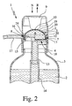
- Fig. 1 shows a first embodiment of a proposed dispensing device 1 for dispensing a preferably cosmetic liquid 2, in the sense mentioned.
- the liquid 2 can be much higher than water viskos or possibly even pasty.
- the dispensing device 1 is preferably associated with a container 3 for supply with the liquid 2, to which the dispensing device 1 is releasably attached as needed. Thus, if necessary, an exchange of the container 3 and / or a refilling of the liquid 2 take place.
- the dispenser 1 may also form a reservoir for the liquid 2 or the container.
- the dispensing device 1 has a lower part 4 and a component 5, in particular an upper part.
- the terms "lower part” and “upper part” correspond to the illustration in accordance with Fig. 1 the preferred arrangement or orientation of the dispensing device 1 during normal use. However, this is not necessarily the case. Accordingly, depending on needs, application, training u.
- the lower part 4 and the building or upper part 5 are also in any spatial orientation to each other or be aligned.
- the lower part 4 is preferably rigid and / or integrally formed, in particular injection molded from a suitable plastic.
- the component 5 is formed elastically deformable. The proposed design of the component 5 will be explained later.
- the dispensing device 1 further has a receiving or pumping chamber 6 for the liquid 2, which is in particular formed or limited exclusively before or between the component 5 and the lower part 4.
- the component 5 optionally together with the lower part 4 forms an inlet valve 7 and / or an outlet valve 8.
- the valves 7, 8 may also be formed separately. Due to the valves 7, 8, the functionality of a pump is preferably made possible.
- the valves 7, 8 are preferably designed as self-closing one-way valves.
- FIG. Fig. 1 When the pumping space 6 is filled with liquid 2, as in FIG Fig. 1 represented, can be reduced by deforming the component 5, the volume of the pump chamber 6 and thereby liquid 2 displaced from the pump chamber 6 and output.
- an optional actuator 9 is preferably depressed manually in the direction of the arrow N and thereby at least one operating portion 10 of the component 5.
- the displaced liquid 2 is discharged via the outlet valve 8 and discharged.
- the opening of the outlet valve 8 takes place in particular automatically, preferably due to the fluid pressure, and / or - possibly additionally - due to a corresponding deformation of the component 5 during depression.
- the component 5 preferably has an at least substantially circumferential annular portion 11 which forms in particular the inlet valve 7 and / or the outlet valve 8.
- the ring portion 11 is preferably at least substantially over its entire peripheral extent of the lower part 4 radially supported from the outside and / or inside.
- the annular portion 11 is elastically deflectable at least in regions radially inwardly, namely at least in the region of an inlet opening 12 formed preferably in the lower part 4. In undeflected state covers and closes the ring section 9, the inlet opening 12.
- the annular portion 11 When resetting the component 5 or suction of liquid 2, the annular portion 11 is deflected due to the liquid pressure arising in the inlet opening 12, thereby releasing the inlet opening 12 for the liquid 2.
- the annular portion 11 thus forms, together with the lower part 4 and the inlet opening 12 in the illustrated example, the inlet valve. 7
- the ring portion 11 is preferably formed at least substantially hollow cylindrical.
- the annular wall is reduced or tapered towards its free axial end in its radial thickness.
- the annular portion 9 can also be provided with an opening, a recess, an axial slot or the like in order to form a desired passage and / or to permit a desired, in particular radial, deflection or deformation.
- the dispensing device 1 in the illustrated embodiment preferably a connecting piece 13 with a connected thereto, extending into the container 2 suction hose 14 od.
- the connecting piece 13 is integrally formed on the lower part 4.
- the outlet valve 8 is preferably arranged diametrically opposite the intake valve 7 with respect to the axis of the annular portion 11.
- the ring portion 11 is supported radially inwardly, preferably by a wall portion 15 of the lower part 4.
- Particularly preferred is the wall portion 15 formed by an inner elevation of the lower part 4 in the pump chamber 6.
- the ring section 11 covers an outlet opening 16 formed in the wall section 15 radially on the outside.
- the ring portion 11 is elastically biased against the outlet opening 16 - ie radially inwardly - or covers the outlet opening 16 at least loosely.
- liquid 2 located in the pump chamber 6 is pressurized so that it deflects the annular section 11 radially outward in the region of the outlet opening 16, whereby the outlet valve 8 is opened is and the output of the liquid 2, in particular via a subsequent, for example, trunk-like discharge channel 17, can take place.
- the exhaust valve 8 closes again - at least substantially completely, in particular due to the inherent elasticity or restoring force of the annular section 11.
- valves 7, 8 open and close at least substantially by axial movement or deflection or deformation of the ring section 11 and / or at least substantially perpendicular to the main operating direction or depression direction N of the component 5 or of the actuating section 10, however Arrangements possible.
- the dispensing of liquid 2 by the dispensing device 1 takes place in particular in a non-atomized state. In principle, however, a sputtering of the liquid 2 by means of the dispensing device 1 is possible.
- the dispensing device 1 preferably has a connecting part 18 for holding the component 5 and in particular connection of the component 5 with the lower part 4.
- the connecting part 18 is substantially sleeve-shaped and / or rigid - at least in comparison to the component 5 - formed.
- the connecting part 18 is molded directly onto the component 5, in particular by so-called "bi-injection", ie spraying of another material against a first material.
- the component 5 is mounted peripherally peripherally on the connecting part 18 and held.
- the lower part 4 is preferably inserted into the connecting part 18, for example glued, clamped or engaged.
- the component 5 is connected only directly to the lower part 4 or is preferably held at least substantially self-sealing and / or self-holding on the lower part 4. If necessary, in addition can intermesh for connection and undercut sections, detents or the like.
- the component 5 was made in one piece from a single material. However, according to the proposal, the component 5 is modified, as explained in particular below and / or disclosed in the claims.
- the component 5 forms a preferably continuous, in particular curved wall 19 at least in the region of the pump chamber 6.
- the wall 19 forms in particular the primary deformable region, in particular actuating portion 10, of the component 5.
- the component 5 or the wall 19 preferably dome-shaped or dome-shaped, in particular hemispherical, formed.
- the wall 19 is made of a first material.
- the component 5 at least substantially consists of this first material, in particular its other sections or areas, as in the illustrated embodiment of the ring section 11, alternatively or additionally but also other preferably integrally molded sections, such as valve flaps, supports, holding sections, flange sections, reinforcements , od.
- the component 5 at least substantially consists of this first material, in particular its other sections or areas, as in the illustrated embodiment of the ring section 11, alternatively or additionally but also other preferably integrally molded sections, such as valve flaps, supports, holding sections, flange sections, reinforcements , od.
- the component 5 is provided in particular at least in the region of the pumping space 6 or the wall 19 with an element 20 made of a second material.
- the element 20 is formed here, for example, flat, fibrous or lattice-like.
- the element 20 is also made by injection molding or other suitable means.
- the component 5 is preferably injection-molded.
- the first material is preferably a plastic, in particular an elastomer and / or thermoplastic. However, it can basically also be a different material. This is especially true if the component 5 is not (only) the wall 19 for the pump chamber 6 or another pump part, but another component of the dispensing device 1 forms.
- the first material is preferably an elastomer, rubber or other thermoplastic. Preference is given to using TBE (thermoplastic elastomer), TPV, TEEE (thermoplastic elastomers with ether and ester groups) or TPO (thermoplastic urethanes).
- TBE thermoplastic elastomer
- TPV thermoplastic elastomer
- TEEE thermoplastic elastomers with ether and ester groups
- TPO thermoplastic urethanes
- the second material is also an elastomer and / or a thermoplastic, but if necessary also another material.
- the second material is a polyolefin, in particular PP (polypropylene) or PE (polyethylene).
- first material and the second material are different, ie have at least different properties and / or at least different compositions.
- the combination of different materials makes it much easier to achieve the desired properties of the component 5, for example in the region of the wall 19 or in the region which is elastically deformable for the pumping.
- the element 20 serves to optimize the elastic properties of the component 5 or the wall 19, in particular the elastic return. Due to the integration in the first material or the wall 19, the second material does not come into contact with the liquid 2. Accordingly, an optimum material for the elastic properties can be used regardless of its chemical resistance to the liquid 2.
- the element 20 is permanently connected to the component 5 or its wall 19.
- the element 20 may also be injection-molded on its own or, conversely, the wall 19 may be sprayed against the element 20, particularly preferably by the "bi-injection" already mentioned.
- the element 20 can in principle also be connected to the component 5 or the wall 19 by gluing, welding or in any other suitable manner.
- the first material of the component 5 is preferably completely covered by the second material in the region which is in contact or comes into contact with the liquid 2.
- the element 20 thus forms a continuous cover or layer or coating of the second material.
- the second material or the layer is preferably fixed, insoluble and / or full surface connected to the first material.
- the second material may in particular be molded onto the first material by the so-called "bi-injection", the first material partially having or forming an at least substantially smooth or rough surface or a surface provided with undercuts, recesses, perforations or the like can.
- the element 20 or the material layer may also be connected only in regions, for the first time, or held together with the latter - for example in edge or peripheral areas.
- the element 20 may also form only a particular membrane-like part which is inserted or arranged between liquid 2 and component 5.
- the second Material also form a shell, which preferably completely surrounds the first material. Also in this case, a direct connection of the two materials is not required.
- the liquid-side or inside arrangement of the second material or cover of the first material protects the first material against chemical influences, in particular by the liquid 2 and / or the liquid 2 from chemical influences of the first material or other interactions. It is thus possible, for example, to use non-food-grade materials and / or non-liquid-resistant materials as the first material in order, for example, to achieve cost-effective production and / or certain mechanical or other properties.
- the second material can then fulfill the desired food-fastness or resistance to the liquid 2.
- the element 20 or the second material covers the pump chamber 6 facing surface of the wall 19, the inside, outside and the end face of the adjoining ring portion 11 and the radially adjacent annular region of the annular die 24 of the component 5.
- this extends second material or the layer or cover formed therefrom up to or even below another material or component that is resistant or inert to the liquid 2, in the illustrated example the lower part 4 or the connecting part 18.
- the second material or element 20 can also serve to modify the elastic properties or other properties of the component 5.
- the present invention is not limited to elastic or flexible, in particular so deformable components. Rather, the cover by the second material generally also in any type of component of a dispenser 1 are used in the context of the present invention, in particular to prevent direct contact between liquid 2 and material.
- the element 20 on the pump chamber 6 facing away from the side of the component 5 and the wall 19 - that is outside - arranged.
- the element 20 is designed here in particular as a continuous material layer or cover.
- the element 20 is sprayed directly onto the first material, in particular by the said "bi-injection" or the like.
- the element 20 serves in this case again in particular to optimize the return properties, in particular in order to be able to achieve a sufficiently high restoring force.
- the element 20 may protect the component 5, in particular the wall 19 or the actuating portion 10, against mechanical or other influences.
- the cover formed by the element 20 can also prevent the escape of plasticizers from the first material so as to be able to ensure desired material properties of the first material.
- the element 20 may additionally be arranged on the side facing the pumping space 6-that is, inside-of the component 5 or the wall 19.
- the element 20 may protect the first material against chemical influences, in particular by the liquid 2.
- the material that is in contact or coming into contact with the pumping space 6 or the liquid 2 is the first and / or second material.
- the element 20 is preferably connected to the wall 19 over its entire surface. However, it is also possible in principle that the element 20 is only partially connected to the wall 19, for example only along welding lines.
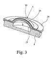
- Fig. 4 shows a fourth embodiment of the proposed component 5.
- the element 20 is arranged here on the outside of the wall 19.
- the element 20 does not cover the wall 19 completely, so it is not formed continuously, but in particular provided with openings or openings.
- the element 20 in particular rib-like or web-like portions 21 which connect an inner ring 22 with an outer ring 23 of the element 20 - preferably radially and / or with a curved course.
- By appropriate adaptation for example of number, cross-section, width, height, course of the sections 21, the dimensioning of the inner ring 22 and / or the outer ring 23, selection of a corresponding material u.
- the desired recovery behavior is very easy to implement.
- the outer ring 23 is preferably connected on the axial side or the entire surface with an annular flange 24 of the component 5, which connects radially to the wall 19.
- the ring 22 or another region of the wall 19, possibly reinforced or covered by the element 20, can form the actuating section 10 or an abutment or support for the actuating element 9.
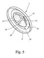
- Fig. 5 shows a fifth embodiment of the proposed component 5 from below.
Landscapes
- Containers And Packaging Bodies Having A Special Means To Remove Contents (AREA)
- Reciprocating Pumps (AREA)
- External Artificial Organs (AREA)
- Structures Of Non-Positive Displacement Pumps (AREA)
Claims (15)
- Dispositif de distribution (1) pour un liquide (2) de préférence cosmétique, comprenant un constituant élastique ou flexible (5) ;
caractérisé
en ce que le constituant (5) présente une paroi (19) constituée d'un premier matériau et un élément (20) qui y est relié et/ou qui le recouvre, constitué d'un deuxième matériau ; et
en ce que l'élément (20) présente des tronçons (21) en forme de côtes ou de nervures, s'étendant par-dessus la paroi (19). - Dispositif de distribution selon la revendication 1, caractérisé en ce que l'élément (20) est relié de manière inamovible à la paroi (19).
- Dispositif de distribution selon la revendication 1 ou 2, caractérisé en ce que l'élément (20) est collé ou soudé à la paroi (19) ou en ce que l'élément (20) est appliqué contre ou dans la paroi (19) par moulage par injection.
- Dispositif de distribution selon l'une quelconque des revendications précédentes, caractérisé en ce que l'élément (20) forme une couche de matière ou un revêtement continu, et/ou en ce que l'élément (20) protège le premier matériau respectivement la paroi (19) contre les influences chimiques et/ou mécaniques.
- Dispositif de distribution selon l'une quelconque des revendications précédentes, caractérisé en ce que l'élément (20) provoque ou soutient de manière essentielle ou de manière exclusive un renvoi élastique du constituant (5) et/ou en ce que l'élément (20) est relié sur toute sa surface à la paroi (19) respectivement au premier matériau.
- Dispositif de distribution selon l'une quelconque des revendications précédentes, caractérisé en ce que la paroi (19) prend la forme d'une coupole.
- Dispositif de distribution selon l'une quelconque des revendications précédentes, caractérisé en ce que le constituant (5) respectivement la paroi (19) délimite ou forme un espace de pompage (6) du dispositif de distribution (1), en particulier dans lequel du liquide (2) peut être distribué à partir de l'espace de pompage (6) via une déformation, en particulier manuelle, du constituant (5), en particulier via l'enfoncement d'un tronçon d'activation (10) du constituant (5) et/ou dans lequel du liquide (2) peut venir se loger, de préférence par aspiration, dans l'espace de pompage (6) via un renvoi élastique, de préférence automatique, du constituant (5) respectivement du tronçon d'actionnement (10).
- Dispositif de distribution selon la revendication 7, caractérisé en ce que l'élément (20) est disposé sur le côté de la paroi (19) qui se tourne vers l'espace de pompage (6) ou qui s'en détourne.
- Dispositif de distribution selon l'une quelconque des revendications précédentes, caractérisé en ce que le constituant forme une paroi (19) pour le liquide (2).
- Dispositif de distribution selon l'une quelconque des revendications précédentes, caractérisé en ce que le premier matériau et le deuxième matériau sont différents en ce qui concerne leur composition, leur résistance vis-à-vis du liquide (2) et/ou leurs autres propriétés.
- Dispositif de distribution selon l'une quelconque des revendications précédentes, caractérisé en ce que le deuxième matériau forme une couche continue, respectivement un revêtement continu.
- Dispositif de distribution selon l'une quelconque des revendications précédentes, caractérisé en ce que le deuxième matériau résiste au liquide (2).
- Dispositif de distribution selon l'une quelconque des revendications précédentes, caractérisé en ce que le deuxième matériau est acceptable pour les aliments.
- Dispositif de distribution selon l'une quelconque des revendications précédentes, caractérisé en ce que le deuxième matériau est une polyoléfine, en particulier du polypropylène ou du polyéthylène,
- Dispositif de distribution selon l'une quelconque des revendications précédentes, caractérisé en ce que le premier matériau est une matière synthétique, en particulier un élastomère et/ou une matière thermoplastique.
Applications Claiming Priority (3)
| Application Number | Priority Date | Filing Date | Title |
|---|---|---|---|
| DE102005057686 | 2005-12-01 | ||
| DE102005060167.7A DE102005060167B4 (de) | 2005-12-01 | 2005-12-14 | Abgabevorrichtung |
| PCT/EP2006/011455 WO2007062824A1 (fr) | 2005-12-01 | 2006-11-29 | Dispositif de liberation a paroi flexible renforcee |
Publications (2)
| Publication Number | Publication Date |
|---|---|
| EP1954404A1 EP1954404A1 (fr) | 2008-08-13 |
| EP1954404B1 true EP1954404B1 (fr) | 2011-01-12 |
Family
ID=37829508
Family Applications (1)
| Application Number | Title | Priority Date | Filing Date |
|---|---|---|---|
| EP06829182A Active EP1954404B1 (fr) | 2005-12-01 | 2006-11-29 | Pompe de distribution à paroi flexible renforcée |
Country Status (6)
| Country | Link |
|---|---|
| US (1) | US20100032451A1 (fr) |
| EP (1) | EP1954404B1 (fr) |
| AT (1) | ATE494959T1 (fr) |
| DE (2) | DE102005060167B4 (fr) |
| ES (1) | ES2359436T3 (fr) |
| WO (1) | WO2007062824A1 (fr) |
Families Citing this family (7)
| Publication number | Priority date | Publication date | Assignee | Title |
|---|---|---|---|---|
| DE102006012302A1 (de) | 2006-03-15 | 2007-09-27 | Seaquist Perfect Dispensing Gmbh | Abgabevorrichtung |
| DE102006030829B4 (de) | 2006-05-12 | 2019-10-24 | Aptar Dortmund Gmbh | Abgabevorrichtung und Verfahren zu dessen Herstellung |
| DE102007049614B4 (de) | 2007-03-15 | 2015-03-05 | Aptar Dortmund Gmbh | Abgabevorrichtung |
| GB0902626D0 (en) * | 2009-02-17 | 2009-04-01 | Farrar Peter A | Combination pack for personal care products |
| GB2483087A (en) * | 2010-08-26 | 2012-02-29 | Breeze Product Design Ltd | Refillable Dispenser with Deformable Membrane |
| FR3004429B1 (fr) * | 2013-04-16 | 2015-11-27 | Rexam Dispensing Sys | Ensemble comprenant un flacon remplissable et une source de produit |
| FR3080100B1 (fr) * | 2018-04-13 | 2021-07-02 | Albea Services | Pompe de distribution de produit fluidique pour flacon de faible hauteur |
Family Cites Families (18)
| Publication number | Priority date | Publication date | Assignee | Title |
|---|---|---|---|---|
| US3130877A (en) * | 1960-10-07 | 1964-04-28 | Formold Plastics Inc | Dispenser and valves for same |
| US3160329A (en) * | 1963-02-26 | 1964-12-08 | Radic Frank | Dispensing device |
| DE1934235U (de) * | 1966-01-07 | 1966-03-10 | Konrad Jauch | Zerstaeuberverschluss fuer fluessigkeitsbehaelter. |
| US3486663A (en) * | 1967-11-16 | 1969-12-30 | Frederick Harold Humphrey | Elastomeric pump and check-valve |
| US4386187A (en) * | 1980-06-11 | 1983-05-31 | Sweetheart Plastics, Inc. | Thermoformable polymer blend composition comprising styrene polymer, olefin polymer and block copolymer |
| ES2057844T3 (es) * | 1990-02-16 | 1994-10-16 | Sterisol Ab | Valvula de distribucion de un fluido. |
| US5207355A (en) * | 1991-12-30 | 1993-05-04 | Thomsen Peter N | High viscosity pump system for dispenser pouch |
| WO1996019389A1 (fr) * | 1994-12-22 | 1996-06-27 | Pentel Kabushiki Kaisha | Conteneur de deversement |
| US5784087A (en) * | 1995-04-27 | 1998-07-21 | Owens-Illinois Closure Inc. | Liquid containment and dispensing device |
| FR2754245B1 (fr) * | 1996-10-07 | 1998-11-27 | Oreal | Recipient a bande(s) de couleur et/ou d'aspect differents |
| NO307079B1 (no) * | 1996-11-12 | 2000-02-07 | Tone Nordvik | Ammeanordning |
| AUPQ391499A0 (en) * | 1999-11-09 | 1999-12-02 | Thomsen, Peter N. | Pump system for a dispenser pouch |
| EP1384004B1 (fr) * | 2001-03-27 | 2009-11-18 | NVB Composites International a/s | Combinaison d'une chambre et d'un piston, pompe, moteur, amortisseur et transducteur integrant ladite combinaison |
| NO315309B1 (no) * | 2001-06-18 | 2003-08-18 | Mamma Lactans As | Brystkopp, samt fremgangsmate ved fremstilling av brystkopp, samt fremgangsmate ved pumping av brystmelk ved hjelp av brystkoppen |
| WO2004073873A2 (fr) * | 2003-02-18 | 2004-09-02 | Incro Limited | Buse pour vaporisation en fines gouttelettes |
| ES2274194T3 (es) * | 2003-09-26 | 2007-05-16 | Edo Giardini | Proceso de fabricacion de una membrana para aparatos de control fluidos y membrana fabricada de acuerdo con el procedimiento. |
| DE202004018315U1 (de) * | 2004-11-26 | 2005-03-03 | Weber, Erhard, Dr. | Verteilungsvorrichtung für den Rücken |
| DE202005012684U1 (de) * | 2005-03-16 | 2005-11-10 | Seaquist Perfect Dispensing Gmbh | Abgabevorrichtung |
-
2005
- 2005-12-14 DE DE102005060167.7A patent/DE102005060167B4/de not_active Expired - Fee Related
-
2006
- 2006-11-29 ES ES06829182T patent/ES2359436T3/es active Active
- 2006-11-29 EP EP06829182A patent/EP1954404B1/fr active Active
- 2006-11-29 DE DE502006008739T patent/DE502006008739D1/de active Active
- 2006-11-29 US US12/085,730 patent/US20100032451A1/en not_active Abandoned
- 2006-11-29 WO PCT/EP2006/011455 patent/WO2007062824A1/fr active Application Filing
- 2006-11-29 AT AT06829182T patent/ATE494959T1/de active
Also Published As
| Publication number | Publication date |
|---|---|
| WO2007062824A1 (fr) | 2007-06-07 |
| DE502006008739D1 (de) | 2011-02-24 |
| DE102005060167B4 (de) | 2016-04-07 |
| ES2359436T3 (es) | 2011-05-23 |
| US20100032451A1 (en) | 2010-02-11 |
| DE102005060167A1 (de) | 2007-06-14 |
| EP1954404A1 (fr) | 2008-08-13 |
| ATE494959T1 (de) | 2011-01-15 |
Similar Documents
| Publication | Publication Date | Title |
|---|---|---|
| EP1993739B1 (fr) | Dispositif distributeur | |
| DE102007049614B4 (de) | Abgabevorrichtung | |
| EP1842798B1 (fr) | Soupape de dosage et dispositif destiné à la livraison d'un liquide cosmétique de préférence | |
| EP1954404B1 (fr) | Pompe de distribution à paroi flexible renforcée | |
| DE102006030829B4 (de) | Abgabevorrichtung und Verfahren zu dessen Herstellung | |
| EP2223749B1 (fr) | Pompe de pulvérisation à gâchette | |
| DE102009030627B4 (de) | Ventil und Abgabevorrichtung | |
| EP2018227B1 (fr) | Dispositif de distribution | |
| EP2885084B1 (fr) | Tête de distribution pour un distributeur ainsi que distributeur comportant une telle tête de distribution | |
| WO2003026803A1 (fr) | Dispositif de dosage muni d'un systeme de pompage | |
| EP2024101A1 (fr) | Distributeur | |
| EP1871539B1 (fr) | Distributeur utilise pour la distribution des masses fluides et pateuses | |
| DE602004005607T2 (de) | Fluidproduktabgabekopf | |
| EP3730220A1 (fr) | Distributeur destiné à la sortie des liquides pharmaceutiques | |
| EP3378348B1 (fr) | Distributeur de liquide comprenant une éponge d'application | |
| EP1295645B1 (fr) | Dispositif de dosage muni d'une pompe | |
| EP3021983A1 (fr) | Tête de distribution, et distributeur pour un milieu de préférence pâteux | |
| DE602004010815T2 (de) | Fluidproduktabgabekopf und dessen verwendung | |
| WO2007122087A1 (fr) | Distributeur pour distribuer des masses de consistance liquide à pâteuse | |
| EP3736049B1 (fr) | Tête distributrice et distributeur de liquide comprenant une tête distributrice | |
| EP3730219A1 (fr) | Distributeur destiné à la sortie des liquides pharmaceutiques | |
| DE202006011682U1 (de) | Abgabevorrichtung | |
| DE202005012684U1 (de) | Abgabevorrichtung | |
| EP1160178A2 (fr) | Tête de distribution pour un récipient sous pression contenant une substance pateuse | |
| DE202008010214U1 (de) | Abgabevorrichtung |
Legal Events
| Date | Code | Title | Description |
|---|---|---|---|
| PUAI | Public reference made under article 153(3) epc to a published international application that has entered the european phase |
Free format text: ORIGINAL CODE: 0009012 |
|
| 17P | Request for examination filed |
Effective date: 20080521 |
|
| AK | Designated contracting states |
Kind code of ref document: A1 Designated state(s): AT BE BG CH CY CZ DE DK EE ES FI FR GB GR HU IE IS IT LI LT LU LV MC NL PL PT RO SE SI SK TR |
|
| GRAP | Despatch of communication of intention to grant a patent |
Free format text: ORIGINAL CODE: EPIDOSNIGR1 |
|
| RTI1 | Title (correction) |
Free format text: DELIVERY PUMP WITH A REINFORCED, FLEXIBLE WALL |
|
| DAX | Request for extension of the european patent (deleted) | ||
| RTI1 | Title (correction) |
Free format text: DELIVERY PUMP WITH A REINFORCED, FLEXIBLE WALL |
|
| GRAS | Grant fee paid |
Free format text: ORIGINAL CODE: EPIDOSNIGR3 |
|
| GRAA | (expected) grant |
Free format text: ORIGINAL CODE: 0009210 |
|
| AK | Designated contracting states |
Kind code of ref document: B1 Designated state(s): AT BE BG CH CY CZ DE DK EE ES FI FR GB GR HU IE IS IT LI LT LU LV MC NL PL PT RO SE SI SK TR |
|
| REG | Reference to a national code |
Ref country code: GB Ref legal event code: FG4D Free format text: NOT ENGLISH |
|
| REG | Reference to a national code |
Ref country code: CH Ref legal event code: EP |
|
| REG | Reference to a national code |
Ref country code: IE Ref legal event code: FG4D Free format text: LANGUAGE OF EP DOCUMENT: GERMAN |
|
| REF | Corresponds to: |
Ref document number: 502006008739 Country of ref document: DE Date of ref document: 20110224 Kind code of ref document: P |
|
| REG | Reference to a national code |
Ref country code: DE Ref legal event code: R096 Ref document number: 502006008739 Country of ref document: DE Effective date: 20110224 |
|
| REG | Reference to a national code |
Ref country code: ES Ref legal event code: FG2A Ref document number: 2359436 Country of ref document: ES Kind code of ref document: T3 Effective date: 20110523 |
|
| REG | Reference to a national code |
Ref country code: NL Ref legal event code: VDEP Effective date: 20110112 |
|
| LTIE | Lt: invalidation of european patent or patent extension |
Effective date: 20110112 |
|
| PG25 | Lapsed in a contracting state [announced via postgrant information from national office to epo] |
Ref country code: GR Free format text: LAPSE BECAUSE OF FAILURE TO SUBMIT A TRANSLATION OF THE DESCRIPTION OR TO PAY THE FEE WITHIN THE PRESCRIBED TIME-LIMIT Effective date: 20110413 Ref country code: IS Free format text: LAPSE BECAUSE OF FAILURE TO SUBMIT A TRANSLATION OF THE DESCRIPTION OR TO PAY THE FEE WITHIN THE PRESCRIBED TIME-LIMIT Effective date: 20110512 Ref country code: PT Free format text: LAPSE BECAUSE OF FAILURE TO SUBMIT A TRANSLATION OF THE DESCRIPTION OR TO PAY THE FEE WITHIN THE PRESCRIBED TIME-LIMIT Effective date: 20110512 Ref country code: SE Free format text: LAPSE BECAUSE OF FAILURE TO SUBMIT A TRANSLATION OF THE DESCRIPTION OR TO PAY THE FEE WITHIN THE PRESCRIBED TIME-LIMIT Effective date: 20110112 Ref country code: LT Free format text: LAPSE BECAUSE OF FAILURE TO SUBMIT A TRANSLATION OF THE DESCRIPTION OR TO PAY THE FEE WITHIN THE PRESCRIBED TIME-LIMIT Effective date: 20110112 Ref country code: LV Free format text: LAPSE BECAUSE OF FAILURE TO SUBMIT A TRANSLATION OF THE DESCRIPTION OR TO PAY THE FEE WITHIN THE PRESCRIBED TIME-LIMIT Effective date: 20110112 |
|
| REG | Reference to a national code |
Ref country code: IE Ref legal event code: FD4D |
|
| PG25 | Lapsed in a contracting state [announced via postgrant information from national office to epo] |
Ref country code: BG Free format text: LAPSE BECAUSE OF FAILURE TO SUBMIT A TRANSLATION OF THE DESCRIPTION OR TO PAY THE FEE WITHIN THE PRESCRIBED TIME-LIMIT Effective date: 20110412 Ref country code: CY Free format text: LAPSE BECAUSE OF FAILURE TO SUBMIT A TRANSLATION OF THE DESCRIPTION OR TO PAY THE FEE WITHIN THE PRESCRIBED TIME-LIMIT Effective date: 20110112 Ref country code: SI Free format text: LAPSE BECAUSE OF FAILURE TO SUBMIT A TRANSLATION OF THE DESCRIPTION OR TO PAY THE FEE WITHIN THE PRESCRIBED TIME-LIMIT Effective date: 20110112 Ref country code: PL Free format text: LAPSE BECAUSE OF FAILURE TO SUBMIT A TRANSLATION OF THE DESCRIPTION OR TO PAY THE FEE WITHIN THE PRESCRIBED TIME-LIMIT Effective date: 20110112 Ref country code: NL Free format text: LAPSE BECAUSE OF FAILURE TO SUBMIT A TRANSLATION OF THE DESCRIPTION OR TO PAY THE FEE WITHIN THE PRESCRIBED TIME-LIMIT Effective date: 20110112 Ref country code: FI Free format text: LAPSE BECAUSE OF FAILURE TO SUBMIT A TRANSLATION OF THE DESCRIPTION OR TO PAY THE FEE WITHIN THE PRESCRIBED TIME-LIMIT Effective date: 20110112 |
|
| PG25 | Lapsed in a contracting state [announced via postgrant information from national office to epo] |
Ref country code: IE Free format text: LAPSE BECAUSE OF FAILURE TO SUBMIT A TRANSLATION OF THE DESCRIPTION OR TO PAY THE FEE WITHIN THE PRESCRIBED TIME-LIMIT Effective date: 20110112 Ref country code: DK Free format text: LAPSE BECAUSE OF FAILURE TO SUBMIT A TRANSLATION OF THE DESCRIPTION OR TO PAY THE FEE WITHIN THE PRESCRIBED TIME-LIMIT Effective date: 20110112 Ref country code: EE Free format text: LAPSE BECAUSE OF FAILURE TO SUBMIT A TRANSLATION OF THE DESCRIPTION OR TO PAY THE FEE WITHIN THE PRESCRIBED TIME-LIMIT Effective date: 20110112 |
|
| PLBE | No opposition filed within time limit |
Free format text: ORIGINAL CODE: 0009261 |
|
| STAA | Information on the status of an ep patent application or granted ep patent |
Free format text: STATUS: NO OPPOSITION FILED WITHIN TIME LIMIT |
|
| PG25 | Lapsed in a contracting state [announced via postgrant information from national office to epo] |
Ref country code: SK Free format text: LAPSE BECAUSE OF FAILURE TO SUBMIT A TRANSLATION OF THE DESCRIPTION OR TO PAY THE FEE WITHIN THE PRESCRIBED TIME-LIMIT Effective date: 20110112 Ref country code: RO Free format text: LAPSE BECAUSE OF FAILURE TO SUBMIT A TRANSLATION OF THE DESCRIPTION OR TO PAY THE FEE WITHIN THE PRESCRIBED TIME-LIMIT Effective date: 20110112 Ref country code: CZ Free format text: LAPSE BECAUSE OF FAILURE TO SUBMIT A TRANSLATION OF THE DESCRIPTION OR TO PAY THE FEE WITHIN THE PRESCRIBED TIME-LIMIT Effective date: 20110112 |
|
| 26N | No opposition filed |
Effective date: 20111013 |
|
| REG | Reference to a national code |
Ref country code: DE Ref legal event code: R097 Ref document number: 502006008739 Country of ref document: DE Effective date: 20111013 |
|
| BERE | Be: lapsed |
Owner name: SEAQUIST PERFECT DISPENSING G.M.B.H. Effective date: 20111130 |
|
| PG25 | Lapsed in a contracting state [announced via postgrant information from national office to epo] |
Ref country code: MC Free format text: LAPSE BECAUSE OF NON-PAYMENT OF DUE FEES Effective date: 20111130 |
|
| REG | Reference to a national code |
Ref country code: CH Ref legal event code: PL |
|
| PG25 | Lapsed in a contracting state [announced via postgrant information from national office to epo] |
Ref country code: CH Free format text: LAPSE BECAUSE OF NON-PAYMENT OF DUE FEES Effective date: 20111130 Ref country code: LI Free format text: LAPSE BECAUSE OF NON-PAYMENT OF DUE FEES Effective date: 20111130 |
|
| PG25 | Lapsed in a contracting state [announced via postgrant information from national office to epo] |
Ref country code: BE Free format text: LAPSE BECAUSE OF NON-PAYMENT OF DUE FEES Effective date: 20111130 |
|
| REG | Reference to a national code |
Ref country code: DE Ref legal event code: R082 Ref document number: 502006008739 Country of ref document: DE Representative=s name: VON ROHR PATENTANWAELTE PARTNERSCHAFT, DE |
|
| REG | Reference to a national code |
Ref country code: AT Ref legal event code: MM01 Ref document number: 494959 Country of ref document: AT Kind code of ref document: T Effective date: 20111129 |
|
| PG25 | Lapsed in a contracting state [announced via postgrant information from national office to epo] |
Ref country code: AT Free format text: LAPSE BECAUSE OF NON-PAYMENT OF DUE FEES Effective date: 20111129 |
|
| PG25 | Lapsed in a contracting state [announced via postgrant information from national office to epo] |
Ref country code: LU Free format text: LAPSE BECAUSE OF NON-PAYMENT OF DUE FEES Effective date: 20111129 |
|
| REG | Reference to a national code |
Ref country code: DE Ref legal event code: R082 Ref document number: 502006008739 Country of ref document: DE Representative=s name: VON ROHR PATENTANWAELTE PARTNERSCHAFT, DE |
|
| REG | Reference to a national code |
Ref country code: DE Ref legal event code: R081 Ref document number: 502006008739 Country of ref document: DE Owner name: APTAR DORTMUND GMBH, DE Free format text: FORMER OWNER: SEAQUIST PERFECT DISPENSING GMBH, 44319 DORTMUND, DE Effective date: 20130611 Ref country code: DE Ref legal event code: R082 Ref document number: 502006008739 Country of ref document: DE Representative=s name: VON ROHR PATENTANWAELTE PARTNERSCHAFT, DE Effective date: 20121220 Ref country code: DE Ref legal event code: R082 Ref document number: 502006008739 Country of ref document: DE Representative=s name: VON ROHR PATENTANWAELTE PARTNERSCHAFT, DE Effective date: 20130611 Ref country code: DE Ref legal event code: R082 Ref document number: 502006008739 Country of ref document: DE Representative=s name: VON ROHR PATENTANWAELTE PARTNERSCHAFT MBB, DE Effective date: 20121220 Ref country code: DE Ref legal event code: R082 Ref document number: 502006008739 Country of ref document: DE Representative=s name: VON ROHR PATENTANWAELTE PARTNERSCHAFT MBB, DE Effective date: 20130611 |
|
| PG25 | Lapsed in a contracting state [announced via postgrant information from national office to epo] |
Ref country code: TR Free format text: LAPSE BECAUSE OF FAILURE TO SUBMIT A TRANSLATION OF THE DESCRIPTION OR TO PAY THE FEE WITHIN THE PRESCRIBED TIME-LIMIT Effective date: 20110112 |
|
| PG25 | Lapsed in a contracting state [announced via postgrant information from national office to epo] |
Ref country code: HU Free format text: LAPSE BECAUSE OF FAILURE TO SUBMIT A TRANSLATION OF THE DESCRIPTION OR TO PAY THE FEE WITHIN THE PRESCRIBED TIME-LIMIT Effective date: 20110112 |
|
| REG | Reference to a national code |
Ref country code: FR Ref legal event code: PLFP Year of fee payment: 10 |
|
| REG | Reference to a national code |
Ref country code: FR Ref legal event code: PLFP Year of fee payment: 11 |
|
| REG | Reference to a national code |
Ref country code: FR Ref legal event code: PLFP Year of fee payment: 12 |
|
| PGFP | Annual fee paid to national office [announced via postgrant information from national office to epo] |
Ref country code: IT Payment date: 20221124 Year of fee payment: 17 Ref country code: GB Payment date: 20221122 Year of fee payment: 17 Ref country code: FR Payment date: 20221128 Year of fee payment: 17 Ref country code: DE Payment date: 20221121 Year of fee payment: 17 |
|
| PGFP | Annual fee paid to national office [announced via postgrant information from national office to epo] |
Ref country code: ES Payment date: 20230125 Year of fee payment: 17 |
|
| P01 | Opt-out of the competence of the unified patent court (upc) registered |
Effective date: 20230517 |
|
| REG | Reference to a national code |
Ref country code: DE Ref legal event code: R119 Ref document number: 502006008739 Country of ref document: DE |
|
| GBPC | Gb: european patent ceased through non-payment of renewal fee |
Effective date: 20231129 |